EP0123807A2 - Driving and detection of back EMF in permanent magnet step motors - Google Patents
Driving and detection of back EMF in permanent magnet step motors Download PDFInfo
- Publication number
- EP0123807A2 EP0123807A2 EP84101735A EP84101735A EP0123807A2 EP 0123807 A2 EP0123807 A2 EP 0123807A2 EP 84101735 A EP84101735 A EP 84101735A EP 84101735 A EP84101735 A EP 84101735A EP 0123807 A2 EP0123807 A2 EP 0123807A2
- Authority
- EP
- European Patent Office
- Prior art keywords
- windings
- drive
- excitation
- permanent magnet
- motor
- Prior art date
- Legal status (The legal status is an assumption and is not a legal conclusion. Google has not performed a legal analysis and makes no representation as to the accuracy of the status listed.)
- Granted
Links
Images


Classifications
-
- G—PHYSICS
- G04—HOROLOGY
- G04C—ELECTROMECHANICAL CLOCKS OR WATCHES
- G04C3/00—Electromechanical clocks or watches independent of other time-pieces and in which the movement is maintained by electric means
- G04C3/14—Electromechanical clocks or watches independent of other time-pieces and in which the movement is maintained by electric means incorporating a stepping motor
- G04C3/143—Means to reduce power consumption by reducing pulse width or amplitude and related problems, e.g. detection of unwanted or missing step
-
- H—ELECTRICITY
- H02—GENERATION; CONVERSION OR DISTRIBUTION OF ELECTRIC POWER
- H02P—CONTROL OR REGULATION OF ELECTRIC MOTORS, ELECTRIC GENERATORS OR DYNAMO-ELECTRIC CONVERTERS; CONTROLLING TRANSFORMERS, REACTORS OR CHOKE COILS
- H02P8/00—Arrangements for controlling dynamo-electric motors of the kind having motors rotating step by step
- H02P8/14—Arrangements for controlling speed or speed and torque
Landscapes
- Engineering & Computer Science (AREA)
- Power Engineering (AREA)
- Physics & Mathematics (AREA)
- General Physics & Mathematics (AREA)
- Control Of Stepping Motors (AREA)
- Control Of Motors That Do Not Use Commutators (AREA)
Abstract
Description
- The present invention relates to the driving and controlling of closed loop step motors. More particularly, it relates to the detection of the back EMF induced in the windings of a step motor by a permanent magnet in the rotor of the motor. The value of this back EMF can be used to indicate the position of the rotor of the motor.
- The use of the windings of a step motor both to drive the motor and to provide the position determining feedback pulses is known in the prior art. In each of the prior art systems, however, the feedback signals from the motor windings must be subjected to complex processing which increases the cost of the system. Such complex processing is required because, whenever current is induced in a winding which is used as a detection winding, voltage drops due to this induced current are added to the back EMF induced by the permanent magnet of the motor. Thus the voltage drops due to the induced currents must be reconstructed and subtracted from the signal from the winding in order to detect the true value of the back EMF induced by the permanent magnet of the motor.
- U.S. Patent US-A-3,282,471 teaches using a reconstructed locked rotor response as the reference signal, which has the effect of subtracting it from the signal from the winding.
- U.S. Patent US-A-4,234,838 uses a similar method on a variable reluctance motor.
- U.S. Patent US-A-4,065,708 teaches the use of a summing amplifier 6 for subtracting the output of amplifier 2 which simulates the voltage drop due to current.
- A major drawback of these methods is the requirement of matching gain coefficients in the reconstruction circuitry with parameters of the motor. Another drawback is that some of these methods involve differentiation which is sensitive to noise and is subject to drift.
- When reconstructing a voltage drop due to an induced current, the inductance and the resistance of the winding enter into the reconstruction calculations. In particular, the winding resistance varies with temperature, introducing a phase error in the detected signal. Although the inductance of the windings of a permanent magnet step motor is often assumed to be constant, in actual fact there often is at least some variation as a function of the angle of the rotor, and some variation as a function of the temperature of the magnetic circuit of the motor. This variation is borne out by the observations of B.C. Kua and K. Butts as discussed in the Test Results section III of their paper entitled "Closed Loop EMF Sensing" published May 1982 in the Proceedings, Eleventh Annual Symposium on Incremental Motion Control Systems and Devices.
- Another prior attempt at separating the induced EMF from the voltage drops due to induced currents is discussed by Toshiro Higuchi in his paper entitled "Closed Loop Control of PM Step Motors by Sensing Back EMF" which was also published in May 1982 in the above Proceedings.
- Mr. Higuchi added special sense coils to the motor and used external transformers to cancel the induced voltage drop component in the sense coils. The drawbacks of this method are increased motor cost and the requirement for tuning the external transformers to match the winding inductance of the motor.
- U.S. Patent US-A-4,255,693 shows another complex method of compensating for the voltage drops due to current. This patent drives the windings of a permanent magnet step motor with a pulse width modulated H driver which regulates the winding current to a predetermined waveform. Because the EMF induced by the permanent magnet of the motor affects the current, the pulse width modulator continually compensates by varying the pulse widths. A filter and phase shifter are used to detect these varying pulse widths which are then used as the indirect equivalent of the EMF induced by the permanent magnet. The object of the present invention is to provide an improved drive and detection circuit for a step motor which excites the step motor in such a way that the true value of the back EMF induced in the windings of the motor can be detected.
- According to the present invention a drive and detection circuit for a step motor of the type having a permanent magnet rotor and two sets of stator windings comprising
- a supply voltage for said step motor,
- drive means connected to said supply voltage for providing excitation of said stator windings, and
- detection means for detecting the value of the back EMF induced in each set of windings by the permanent magnet rotor, is characterised in that
- said drive means provides orthogonal excitation of said stator windings whereby only one set of windings is excited at any instant.
- By exciting the windings of the motor orthogonally the circuit ensures that when one set of windings is excited the other set of windings is not excited and the value of the back EMF detected in the other set of windings is the true value of the induced back EMF. The value of the back EMF can be used to control the excitation of the windings of the motor.
- According to a preferred embodiment of the invention the above drive and detection circuit is characterised in that
said drive means operates to dampen any residual current flowing in each set of windings after the termination of excitation so that there is no residual current flowing in said set of windings when said detection means detects a zero value of the back EMF induced in said set of windings. - In order that the invention may be more readily understood reference will now be made to the Figures of the accompanying drawings, in which:
- Figure 1 shows a schematic of a typical two phase permanent magnet step motor,
- Figure 2 shows the EMF waveforms induced in any one of the windings of each phase of the motor of Figure 1,
- Figure 3 is a simplified schematic of an H drive circuit for one phase of the motor of Figure 1,
- Figure 4 is an equivalent circuit of the circuit of Figure 3 as the drive current is decaying in the winding,
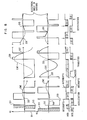
- Figure 5 shows the excitation waveforms when the motor of Figure 1 is running at constant velocity,
- Figure 6 shows a detailed schematic of a drive circuit for driving the two phase permanent magnet step motor of Figure 1 in accordance with the present invention,
- Figure 7 shows a detailed schematic of the components of a circuit used to detect the EMF induced in the stator windings of the motor of Figure 1 by the permanent magnet rotor of the motor in accordance with the present invention,
- Figure 8 shows the voltages at the terminals of the windings of the motor in three conditions: as the motor is accelerated, as the motor operation is changed from steady state run to deceleration, and as the motor is decelerated, and
- Figure 9 is a flow diagram of the microprogram of Table 1 of the specification.
- The direct detection of the back EMF induced in the windings of a permanent magnet step motor as accomplished by a drive and detection circuit in accordance with the present invention is based upon the fact that the open circuit voltage across each phase winding is equal to the back EMF induced in that winding by the permanent magnet of the motor. During operation of many step motors, however, the phase windings are usually not truly open circuited and, in the case of "four phase two on" excitation, the windings are not even magnetically decoupled. Therefore the key to direct detection as accomplished by a circuit in accordance with the present invention lies in the type of drive circuit and in the sequence of excitation of windings which are orthogonal to each other.
- In Figure 1 there is shown a schematic of a two phase permanent magnet step motor having orthogonal windings. In actual implementation, the permanent magnet motor will be constructed as a multi-tooth gear and the stator poles will have corresponding teeth so as to permit many motor steps per revolution of the rotor. These implementation details are well known in the art and will not be described in detail here. Referring again to Figure 1, the
rotor 11 of the motor is shown as including a permanent magnet forming North and South poles at the ends of the rotor. A pair ofstator poles stator poles A poles - As the
permanent magnet rotor 11 rotates, a back EMF will be induced in each one of the windings. Referring now to Figure 2, the waveforms of the EMF induced in each of the windings on the A and B poles is shown in the graph with the zero position along the x-axis corresponding to the position of the rotor as shown in Figure 1. The two waveforms of Figure 2 are simple sinusoidal quadrature waveforms and thus need no further explanation. Each zero crossing of the waveform corresponds with a detent or step angle position of the rotor of the motor. - As mentioned above, important factors in the ability to detect the step motor rotor position directly from the back EMF waveforms are the type of drive circuit employed and the phase excitation sequence. A preferred embodiment of a drive circuit in accordance with the invention is the two phase "H" driver shown in a simplified schematic in Figure 3. This circuit illustrated permits bipolar excitation of one winding from a single supply voltage. Two drive circuits of this type or any other suitable drive circuits are used in such a way that the windings of the two poles are excited orthogonally. In order to be able to detect the zero crossings of the back EMF waveforms, the two pole motor must be driven with only one phase "on" at a time so that each winding is "off" half the time. Also each winding when "off" must be magnetically decoupled from the other winding which is "on". This form of excitation is known as orthogonal excitation.
- As previously mentioned, in order to be able to detect back EMF directly, the winding providing the back EMF signal must effectively be open circuited thereby eliminating any voltage drop due to current flow during excitation or at the end of excitation. Referring again to Figure 3, the open circuit condition of the winding when it is "off" means that all four
transistors transistors diodes suppression diodes terminals - Referring now to Figure 4, an equivalent circuit shows the clamping of the above described inductive kick in a winding to a magnitude not significantly greater than the supply voltage VS as the motor is accelerating. Note for future reference that when the motor is accelerating, the EMF opposes current flow. As will be mentioned later, when the motor is decelerating, the EMF polarity reverses and aids current flow which yields a longer current decay time.
- If, in the previous example,
transistors diodes - With the previous discussion in mind, it can be seen that it is important for the correct operation of a circuit in accordance with the invention that the waveform of the EMF induced in a winding by the permanent magnet rotor will cross zero during the off period of the excitation of that winding in order to be accurately measured.
- Likewise, the rate of decay of current in the winding must be sufficiently high so that the open circuit condition occurs prior to the zero crossing of the waveform of the EMF induced by the permanent magnet rotor. Finally, the motor must be driven as an orthogonal phase machine with only one phase winding "on" at a time so that the "on" and "off" phase windings are decoupled.
- Referring now to Figure 5, typical waveforms of the the voltages in the windings of the A and B poles as the motor is rotating at a constant velocity are shown in the graphs. The y-axis of the graphs represents the voltages VA, VB in the windings of the A and B poles respectively and the x-axis represents the electrical angle through which the rotor of the motor rotates. This electrical angle is greater than the physical angle through which the rotor rotates since, as described above, the stator pole will have a number of teeth corresponding to the number of teeth on the rotor, thereby permitting many motor steps per revolution of the rotor.
- On each graph there are two curves, one representing the voltage across the corresponding pair of windings (A or B) resulting from the supply of excitation pulses and the other representing the EMF induced in the windings by the rotation of the permanent magnet in the rotor of the motor. It will be noted that the curve representing the EMF crosses the zero value (y-axis) for every Tr radians change in the electrical angle.
- The supply of excitation pulses is represented by the lines labelled AIN, BIN, AIN, BIN corresponding respectively to the excitation of the transistor pairs 41,47 and 43,45 for the A and B pairs of windings as illustrated in the drive circuit of Figure 3. Pulses AIN, BIN,
AIN ,BIN follow in sequence with no gaps between successive pulses. When a pulse AIN is supplied to the circuit a positive voltage is produced across the A pole windings for the time length of the pulse. The production of this voltage for the length of the AIN pulse results in the rotation of the rotor through aconduction angle 61. Upon interruption of the excitation pulse AIN an inductive kick is induced resulting in the production of a negative voltage pulse across the A pole windings. This voltage pulse continues for a time during which the rotor rotates through a decay angle 62. - Supply of an AIN pulse results in the production of a negative voltage causing rotation of the rotor through a
conduction angle 65. The interruption of this pulse causes the production of another inductive kick resulting in a positive voltage pulse continuing while the rotor rotates through adecay angle 66. - For the B pole windings, the supply of a pulse BIN results in the production of a positive voltage causing the rotation of the rotor through a
conduction angle 63. The interruption of this pulse results in the production of a negative pulse continuing while the rotor rotates through adecay angle 64. - In order to detect the zero crossings of the waveform of the EMF induced in each winding by the permanent magnet rotor of the motor, the sum of the conduction angle and the decay angle (excitation angle) must lie within the range (-π to 0) in order to provide positive average torque. Likewise, if the sum of these angles lies within the range (0 to π) a negative average torque is provided for decelerating the motor.
- In order to provide a suitably limited conduction angle, it has been found that the use of a low impedance motor with a large supply voltage provides good performance at low cost. This may be explained with reference to Figure 5, where the centre of the conduction angle is located at -Tr/2. This results in maximum average positive torque at low speeds or whenever the current rise and fall times are negligibly small compared to the step period. The use of a low impedance motor thus allows optimum utilisation of available motor torque without allowing the position of the excitation angle to fall outside the range (-π to 0). The use of a low impedance motor and high supply voltage also yields a quick current decay which minimises the decay angle by shortening the decay time, thus providing more flexibility in the positioning of the conduction angle. For example in the limit of zero decay angle, it is possible to vary the conduction angle from one centred at -3π/4 radians to one centred at -Tr/4 radians while maintaining its position within the range from (-π to 0). This arrangement allows some degree of closed loop velocity control over the motor.
- Low motor impedance and high drive voltage are even more important during motor deceleration when the excitation angle is in the range (0 to 1T). During this range of rotation, the collapsing excitation field and the EMF induced by the permanent magnet of the rotor are additive which increases the length of time required for the current in the winding to decay to zero. The large supply voltage and low impedance overcome the effect of the induced EMF due to the permanent magnet of the rotor and provide a rapid current decay.
- Referring again to Figure 5, it can be seen that
conduction angle 61 corresponds to the conduction oftransistors - Figure 3 for the A poles under the control of the input signal AIN. Decay angle 62 corresponds to that period of time when
diodes conduction angle 63 corresponds to the conduction oftransistors Decay angle 64 corresponds to the conduction of current throughdiodes Conduction angle 65 corresponds to the conduction of excitation current throughtransistors Decay angle 66 corresponds to the dissipation of excitation field energy throughdiodes - Prior to discussion of Figure 7, attention will be directed to the detailed drive circuit of Figure 6 which embodies the invention. This circuit comprises a pulse width modulating current limiting circuit including a
current sense resistor 101 and acomparator 103 and abistable circuit 105.Comparator 103 compares the voltage across current sense resistor 101 (which corresponds to the current through one of the motor stator pairs of windings) with a reference voltage derived from a DC supply. When the current inresistor 101 rises to such a level so that the voltage acrossresistor 101 exceeds the reference voltage, thebistable circuit 105 is reset. Whencircuit 105 is reset, its output acts to inhibit output from any of the ANDgates transistors Circuit 105 also receives a clock input signal of 20 kilohertz to repeatedly setbistable circuit 105 after the current inresistor 101 has decayed slightly. In this way, a low impedance motor can be driven from a high voltage supply without causing excessive currents to build up in the motor windings together with the associated excessive temperatures. Referring now to Figure 7, there is shown a detailed schematic of the circuit in accordance with the invention which detects the zero crossings of the waveform of the EMF induced in each winding by the rotation of the permanent magnet rotor. The input terminals at the left of Figure 7 labelled A, A-, B, B- are the terminals of the windings of the A poles and the B poles respectively and correspond to the nodes labelled identically in Figure 6. The inputs at A, A-, B, B- which represent the EMF's induced in the windings, are supplied to the terminals ofdifferential amplifiers Differential amplifiers differential amplifiers comparators 215 and 217 respectively. These comparators compare the now referenced and scaled voltages representing the EMF induced in each winding by the permanent magnet of the rotor to zero volts and provide an output signal as each of the voltages crosses the zero volts value. This output signal is used as an interrupt to the interrupt inputs of a versatileinterface adaptor chip 219. The versatile interface adaptor (VIA) chip interrupt inputs are programmable by a microprocessor to respond either to a rising or a falling edge detection and an interrupt enable register allows independent enabling and masking of the interrupts. Such chips are well known in the art, an example being a SY6522 by SYNERTEK Incorporated. - Under control of a
suitable microprocessor 221, such as the SDY6502 (also by SYNERTEK), programmed in accordance with the microprogram steps listed in Table 1, the interrupt inputs ofVIA 219 are alternately enabled and disabled and, at each interrupt, alternately set for rising and then falling edge detection (block 439 in Figure 9). This allows the detection of each zero crossing of both of the EMF waveforms shown in Figure 2 as they cross from positive to negative and negative to positive values.


- Figure 8 is a timing diagram which illustrates the relationship between the EMF induced in a winding by the permanent magnet of the rotor and the phase select signals which provide the excitation pulses to the windings to drive the motor. In order to get the motor started, two open loop pulses are generated under the control of the microprocessor. Subsequent excitation pulses are initiated by sensing and detecting the zero crossing points of the waveforms of the EMF's induced in the windings by the permanent magnet of the rotor. In this example, the drive circuit is switched so as to provide an excitation pulse to each winding at the instant of the zero crossing of the EMF induced in that winding. This results in a lead angle of two steps. The sequence of events and interrupt control programs are shown in Table 1 and in the flow diagram of Figure 9. The duration of the first excitation pulse into a winding is selected so that for a minimum load, the open circuit condition of the winding at the end of the pulse occurs just before the first zero crossing of the EMF waveform. This provides the maximum adaptability to load increases.
- Referring again to Figure 8 it is assumed that a holding current has been applied to the A pole windings as at statement 34 in Table 1 and block 415 of Figure 9, to keep the motor held at a detent position. After depression of the Go key (block 417) the holding current is turned off at time zero shown at
block 419 of Figure 9. This results in the generation of an inductive kick which is clamped as described with reference to Figures 3, 4. This is represented by the part of the waveform labelled 311 in Figure 8. At the same time as the excitation of the A pole windings is interrupted, the B pole windings are excited as shown at 313. The current limiting action ofcomparator 103 andbistable circuit 105 switching thedrive transistors voltage waveforms Waveforms 319 etc. will have a similar pulse width modulation but for clarity of the illustration, these details are not shown. As the rotor rotates the permanent magnet in the rotor induces an EMF in each of the A pole and B pole windings as illustrated in the graphs in Figure 8. - A 1.6 millisecond time delay is now counted in accordance with statement 58 (block 421 in Figure 9) by the microprocessor before returning to the microprogram at statement 44 (block 423 in Figure 9) to turn on
transistors adaptor 219 is set up to detect the zerocrossing 317 of the EMF induced in the B pole windings by the permanent magnet of the rotor and generate an interrupt signal. The program of Table 1 then waits at statement 57 (block 427 in Figure 9) until the interrupt signal is generated by the circuits in Figure 7. When the interrupt signal is generated, the program jumps to the interrupt service routine at statement 71, (block 429 in Figure 9) which switches off the current in the A pole windings and turns on the current in the B pole windings in accordance with thevoltage waveform 319. Theinductive kick 321 in the A pole windings at the end of the excitation pulse is clamped to the power supply voltage (Figures 3, 4). This causes the A pole windings current to decay long before the EMF induced in the A pole windings by the permanent magnet of the motor crosses zero at 323. This sequence of steps is repeated at each subsequent detection of a zero crossing in either the A pole or B pole windings and the generation of an interrupt signal as in Figure 7 for the acceleration mode of the motor. - After turning on the transistors to drive current through the B pole windings, the program continues to check at
blocks step 79 and then decelerated untilstep 100, at which time a lower steady state current is continuously applied (block 445 in Figure 9) to one of the windings to hold the motor in the stop position. The supply of the lower steady state current is controlled by the pedestal signal labelled PED provided by theversatile interface adaptor 219 to the drive circuit of Figure 6. PED defines a lower value reference voltage which causescomparator 103 to provide shorter voltage pulses to the windings being excited. - The motor is operated with the same interrupt programming for both acceleration and run states. During the run state, the positive acceleration torque just balances the motor load. In order to make the transition from acceleration to deceleration, it is necessary to change the interrupt programming to detect transitions of the opposite polarity and then to introduce a single masking delay.
- This is shown in Figure 8 where the positive
zero crossing transition 330 is masked. Since the responsive polarity of the interrupt input has been changed the interrupt normally provided by the zero crossing at 331 is ignored so as not to cause a change in the current in the winding. Instead, the zero crossing 1800 later at 333 is used to switch the windings and cause currents to flow providing negative torque. As can be seen at 335, the inductive kick in the A pole windings is wider during deceleration because the EMF induced in the windings by the permanent magnet in the rotor adds energy to the inductive kick. So long as the current has decayed to zero before the next zero crossing at 337, this wider current decay pulse does not present a problem. For the remainder of the deceleration mode the motor continues to switch at each zero crossing untilstep 100 where the program ends with the A pole windings excited to hold the motor in the stop position. - After the program has driven the step motor for the 36 steps of the acceleration mode, a switching delay is introduced to reduce the torque to that required to drive the load and cause a constant velocity. This delay which results in the conduction angle in one pair of windings being nearly centred on the zero crossing of the EMF waveform in the other pair of windings is shown clearly in Figure 5 as RUN DELAY. The RUN DELAY is provided in the microprogram of Table 1 by changing the interrupt vector to statement 67 (block 431 in Fig. 9) which introduces a delay routine before the interrupt is serviced at statement 71.
- From the foregoing description of a drive and detection circuit for a step motor, it can be seen that a low impedance two pole step motor can be driven from a relatively high voltage supply in such a way that the zero crossings of the back EMF induced in each winding by the permanent magnet of the rotor can be directly detected and used for the production of pulses to control the operation of the drive circuit of the motor without the need for separate emitters or other velocity or position detecting hardware. The foregoing and other advantages, will be clear to those skilled in the art of step motor control so as to enable them to make and use the drive circuit described.
Claims (7)
characterised in that
said drive means provides orthogonal excitation of said stator windings whereby only one set of windings is excited at any instant.
said drive means (51,53,55,57) operates to dampen any residual current flowing in each set of windings after the termination of excitation so that there is no residual current flowing in said set of windings when said detection means detects a zero value of the back EMF induced in said set of windings.
said drive means comprises for each set of windings a set of four switching devices (41,43,45,47) connected in an H configuration circuit and adapted to provided excitation current to said set of windings, and diode devices (51,53,55,57) connected across said switching devices so as to dampen any current induced in said set of windings when said switching devices are operated to interrupt the supply of excitation current to said windings.
characterised in that
said detector means comprises comparator means (215,217) for comparing said back EMF with a reference voltage.
characterised in that
said drive means comprises current responsive means for limiting the current through any of said windings in order to prevent overheating of said windings.
selectively connecting a supply voltage to each set of stator windings so as to excite said windings in a predetermined sequence and detecting the value of the back EMF induced in each set of windings by said permanent magnet rotor
and using the detection of selected values of said back EMF in order to control the excitation of said sets of windings,
characterised in that
said sets of windings are excited orthogonally so that only one set of windings is excited at any instant.
Applications Claiming Priority (2)
| Application Number | Priority Date | Filing Date | Title |
|---|---|---|---|
| US480049 | 1983-03-29 | ||
| US06/480,049 US4480218A (en) | 1983-03-29 | 1983-03-29 | Direct detection of back EMF in permanent magnet step motors |
Publications (3)
| Publication Number | Publication Date |
|---|---|
| EP0123807A2 true EP0123807A2 (en) | 1984-11-07 |
| EP0123807A3 EP0123807A3 (en) | 1986-01-22 |
| EP0123807B1 EP0123807B1 (en) | 1988-10-26 |
Family
ID=23906471
Family Applications (1)
| Application Number | Title | Priority Date | Filing Date |
|---|---|---|---|
| EP84101735A Expired EP0123807B1 (en) | 1983-03-29 | 1984-02-20 | Driving and detection of back emf in permanent magnet step motors |
Country Status (4)
| Country | Link |
|---|---|
| US (1) | US4480218A (en) |
| EP (1) | EP0123807B1 (en) |
| JP (1) | JPS59181999A (en) |
| DE (1) | DE3474887D1 (en) |
Cited By (4)
| Publication number | Priority date | Publication date | Assignee | Title |
|---|---|---|---|---|
| EP0316077A1 (en) * | 1987-10-31 | 1989-05-17 | Sony Corporation | Brushless motors |
| EP0459066A1 (en) * | 1990-05-25 | 1991-12-04 | The State Of Israel, Ministry Of Defense, Rafael Armament Development Authority | Position-controlled electromagnetic assembly |
| FR2743957A1 (en) * | 1996-01-22 | 1997-07-25 | Magneti Marelli France | Stepping reversible electric motor |
| US7406077B2 (en) | 2003-01-10 | 2008-07-29 | Telefonaktiebolaget Lm Ericsson (Publ) | Generalized rate control for a wireless communications network |
Families Citing this family (56)
| Publication number | Priority date | Publication date | Assignee | Title |
|---|---|---|---|---|
| JPH0640755B2 (en) * | 1985-01-07 | 1994-05-25 | 俊郎 樋口 | Step motor load detection method |
| JPS61177196A (en) * | 1985-01-30 | 1986-08-08 | Mayekawa Mfg Co Ltd | Stepping canned motor having feedback function |
| JPS6292799A (en) * | 1985-10-17 | 1987-04-28 | Silver Seiko Ltd | Driving device for stepping motor |
| US4684866A (en) * | 1986-04-16 | 1987-08-04 | General Motors Corporation | Adaptive controller for a motor vehicle engine throttle operator |
| JP2547061B2 (en) * | 1988-03-15 | 1996-10-23 | 日本電産株式会社 | DC brushless motor start rotation control method |
| US4901000A (en) * | 1989-02-23 | 1990-02-13 | General Motors Corporation | Variable rate stepper motor driver circuit and method |
| JPH02273098A (en) * | 1989-04-14 | 1990-11-07 | Matsushita Electric Ind Co Ltd | Stepping motor drive system |
| US5130620A (en) * | 1991-01-29 | 1992-07-14 | Matsushita Electric Industrial Co., Ltd. | Brushless DC motor without a position sensor |
| WO1993019404A1 (en) * | 1992-03-18 | 1993-09-30 | Citizen Watch Co., Ltd. | Electronic machine with vibratory alarm |
| FR2692417B1 (en) * | 1992-06-12 | 1995-07-28 | Sextant Avionique | SYNCHRONOUS MOTOR CONTROL SYSTEM WITH MAGNET ROTOR. |
| US5615064A (en) * | 1994-10-03 | 1997-03-25 | International Business Machines Corporation | Pulsed current velocity controlled head load method and apparatus which uses the back EMF to control the generation of head actuator driving pulses |
| US5627444A (en) * | 1995-05-30 | 1997-05-06 | General Motors Corporation | Switched reluctance motor control |
| AU719478B2 (en) * | 1997-02-05 | 2000-05-11 | Fisher & Paykel Appliances Limited | Brushless DC motor control |
| DE19846831B4 (en) * | 1998-10-10 | 2008-05-29 | Diehl Ako Stiftung & Co. Kg | Method and device for determining the rotor position of synchronous motors |
| US6046561A (en) * | 1998-11-23 | 2000-04-04 | General Motors Corporation | Commutation control method for a switched reluctance machine |
| US6285155B1 (en) * | 1999-10-29 | 2001-09-04 | Abbott Laboratories | Pseudo half-step motor drive method and apparatus |
| EP1267479A1 (en) * | 2001-06-15 | 2002-12-18 | Saia-Burgess Murten AG | DC brushless motor, method of starting and use thereof |
| US6894450B2 (en) * | 2002-01-16 | 2005-05-17 | Ballard Power Systems Corporation | Circuit configuration for permanent magnet synchronous motor control |
| US6710573B2 (en) * | 2002-03-06 | 2004-03-23 | Andrew S. Kadah | Method of controlling pulsed AC power |
| DE10225610B4 (en) * | 2002-06-07 | 2006-12-28 | Trinamic Motion Control Gmbh & Co. Kg | Method and circuit arrangement for operating a stepper motor |
| EP1460757A1 (en) * | 2003-03-21 | 2004-09-22 | AMI Semiconductor Belgium BVBA | Device and method for detecting rotor speed of a multiple phase motor with bipolar drive |
| US7288910B2 (en) * | 2003-12-01 | 2007-10-30 | Pratt & Whitney Canada Corp. | Sensorless control in a permanent magnet machine |
| US7116070B2 (en) * | 2004-08-23 | 2006-10-03 | Agile Systems Inc. | System and method for sensor less magnetic field control of a motor |
| US7288911B2 (en) | 2005-09-29 | 2007-10-30 | Agile Systems Inc. | System and method for commutating a motor |
| US20070069677A1 (en) * | 2005-09-29 | 2007-03-29 | Mackay David K | System and method for applying energy to a motor |
| US7279860B2 (en) | 2005-09-29 | 2007-10-09 | Agile Systems Inc. | System and method for evaluating back electromotive force in a motor |
| US7592761B2 (en) * | 2005-09-29 | 2009-09-22 | Agile Systems Inc. | System and method for starting and operating a motor |
| US7477034B2 (en) * | 2005-09-29 | 2009-01-13 | Agile Systems Inc. | System and method for commutating a motor using back electromotive force signals |
| US7256564B2 (en) | 2005-09-29 | 2007-08-14 | Agile Systems Inc. | System and method for attenuating noise associated with a back electromotive force signal in a motor |
| US8125174B2 (en) * | 2006-08-07 | 2012-02-28 | Norio Miyauchi | Motor driven electronic apparatus |
| US8517990B2 (en) | 2007-12-18 | 2013-08-27 | Hospira, Inc. | User interface improvements for medical devices |
| US8076882B2 (en) | 2007-12-26 | 2011-12-13 | Pratt & Whitney Canada Corp. | Motor drive architecture with active snubber |
| EP2363950B1 (en) * | 2010-02-18 | 2013-04-03 | Société Industrielle de Sonceboz S.A. | Actuator system with stepping motor |
| US9240002B2 (en) | 2011-08-19 | 2016-01-19 | Hospira, Inc. | Systems and methods for a graphical interface including a graphical representation of medical data |
| US10022498B2 (en) | 2011-12-16 | 2018-07-17 | Icu Medical, Inc. | System for monitoring and delivering medication to a patient and method of using the same to minimize the risks associated with automated therapy |
| JP6306566B2 (en) | 2012-03-30 | 2018-04-04 | アイシーユー・メディカル・インコーポレーテッド | Air detection system and method for detecting air in an infusion system pump |
| US20130319450A1 (en) * | 2012-06-03 | 2013-12-05 | M.M. & R. Products, Inc. | Hairstyling Tool With Automatically Reversing Cylinder |
| CA3089257C (en) | 2012-07-31 | 2023-07-25 | Icu Medical, Inc. | Patient care system for critical medications |
| AU2014268355B2 (en) | 2013-05-24 | 2018-06-14 | Icu Medical, Inc. | Multi-sensor infusion system for detecting air or an occlusion in the infusion system |
| ES2845748T3 (en) | 2013-05-29 | 2021-07-27 | Icu Medical Inc | Infusion system and method of use that prevent oversaturation of an analog-digital converter |
| EP3003441B1 (en) | 2013-05-29 | 2020-12-02 | ICU Medical, Inc. | Infusion system which utilizes one or more sensors and additional information to make an air determination regarding the infusion system |
| AU2015222800B2 (en) | 2014-02-28 | 2019-10-17 | Icu Medical, Inc. | Infusion system and method which utilizes dual wavelength optical air-in-line detection |
| AU2015266706B2 (en) | 2014-05-29 | 2020-01-30 | Icu Medical, Inc. | Infusion system and pump with configurable closed loop delivery rate catch-up |
| US11344668B2 (en) | 2014-12-19 | 2022-05-31 | Icu Medical, Inc. | Infusion system with concurrent TPN/insulin infusion |
| US10850024B2 (en) | 2015-03-02 | 2020-12-01 | Icu Medical, Inc. | Infusion system, device, and method having advanced infusion features |
| WO2017197024A1 (en) | 2016-05-13 | 2017-11-16 | Icu Medical, Inc. | Infusion pump system and method with common line auto flush |
| WO2017214441A1 (en) | 2016-06-10 | 2017-12-14 | Icu Medical, Inc. | Acoustic flow sensor for continuous medication flow measurements and feedback control of infusion |
| US10063170B2 (en) | 2016-06-15 | 2018-08-28 | Texas Instruments Incorporated | Methods and apparatus for robust and efficient stepper motor BEMF measurement |
| US10807729B2 (en) | 2017-05-17 | 2020-10-20 | General Electric Company | Propulsion system for an aircraft |
| US10089055B1 (en) | 2017-12-27 | 2018-10-02 | Icu Medical, Inc. | Synchronized display of screen content on networked devices |
| US11088642B2 (en) | 2019-11-17 | 2021-08-10 | Scnewton Inc. | Electric winding exchanger system |
| US11278671B2 (en) | 2019-12-04 | 2022-03-22 | Icu Medical, Inc. | Infusion pump with safety sequence keypad |
| EP4185260A1 (en) | 2020-07-21 | 2023-05-31 | ICU Medical, Inc. | Fluid transfer devices and methods of use |
| WO2022038406A1 (en) * | 2020-08-17 | 2022-02-24 | Scnewton Inc | Electric winding exchanger system |
| US11135360B1 (en) | 2020-12-07 | 2021-10-05 | Icu Medical, Inc. | Concurrent infusion with common line auto flush |
| US11901845B2 (en) | 2022-03-03 | 2024-02-13 | Ali Sarikhani | Integrated assembly of an electric winding exchanger system and a multiphase electric motor |
Citations (2)
| Publication number | Priority date | Publication date | Assignee | Title |
|---|---|---|---|---|
| FR2425756A1 (en) * | 1978-05-12 | 1979-12-07 | Portescap | STEP BY STEP ELECTRIC MICROMOTOR |
| US4255693A (en) * | 1979-10-29 | 1981-03-10 | International Business Machines Corporation | Closed loop stepper motor circuitry without encoder |
Family Cites Families (9)
| Publication number | Priority date | Publication date | Assignee | Title |
|---|---|---|---|---|
| JPS5211514B2 (en) * | 1972-01-31 | 1977-03-31 | ||
| DE2311904C2 (en) * | 1973-03-09 | 1975-03-20 | Siemens Ag, 1000 Berlin Und 8000 Muenchen | Arrangement for speed control of a direct current motor equipped with an electronic commutation device |
| DE2447673A1 (en) * | 1974-10-05 | 1976-04-08 | Ibm Deutschland | PROCEDURE AND ARRANGEMENT FOR STEPPER MOTOR CONTROL |
| JPS5211514U (en) * | 1975-07-14 | 1977-01-26 | ||
| US4234838A (en) * | 1979-01-11 | 1980-11-18 | Kollmorgen Technologies Corporation | Incremental motion motor controller |
| US4223260A (en) * | 1978-08-31 | 1980-09-16 | The Valeron Corporation | Stepper motor drive apparatus |
| JPS55127897A (en) * | 1979-03-26 | 1980-10-03 | Janome Sewing Mach Co Ltd | Pulse-motor-driving circuit |
| US4282471A (en) * | 1979-05-14 | 1981-08-04 | Qwint Systems Inc. | Control system for a multi-phase motor |
| JPS5619473A (en) * | 1979-07-27 | 1981-02-24 | Citizen Watch Co Ltd | Electronic timepiece |
-
1983
- 1983-03-29 US US06/480,049 patent/US4480218A/en not_active Expired - Fee Related
-
1984
- 1984-02-08 JP JP59020144A patent/JPS59181999A/en active Granted
- 1984-02-20 EP EP84101735A patent/EP0123807B1/en not_active Expired
- 1984-02-20 DE DE8484101735T patent/DE3474887D1/en not_active Expired
Patent Citations (2)
| Publication number | Priority date | Publication date | Assignee | Title |
|---|---|---|---|---|
| FR2425756A1 (en) * | 1978-05-12 | 1979-12-07 | Portescap | STEP BY STEP ELECTRIC MICROMOTOR |
| US4255693A (en) * | 1979-10-29 | 1981-03-10 | International Business Machines Corporation | Closed loop stepper motor circuitry without encoder |
Non-Patent Citations (1)
| Title |
|---|
| SCHMUCK & UHREN, no. 16, August 1981, pages 1-10, Ulm; H. EFFENBERGER et al.: "Elektronisch selbstgesteuerter einphasiger Mikromotor" * |
Cited By (7)
| Publication number | Priority date | Publication date | Assignee | Title |
|---|---|---|---|---|
| EP0316077A1 (en) * | 1987-10-31 | 1989-05-17 | Sony Corporation | Brushless motors |
| US4874993A (en) * | 1987-10-31 | 1989-10-17 | Sony Corporation | Sensorless brushless motor |
| EP0548059A2 (en) * | 1987-10-31 | 1993-06-23 | Sony Corporation | Brushless motors |
| EP0548059A3 (en) * | 1987-10-31 | 1993-07-28 | Sony Corporation | Brushless motors |
| EP0459066A1 (en) * | 1990-05-25 | 1991-12-04 | The State Of Israel, Ministry Of Defense, Rafael Armament Development Authority | Position-controlled electromagnetic assembly |
| FR2743957A1 (en) * | 1996-01-22 | 1997-07-25 | Magneti Marelli France | Stepping reversible electric motor |
| US7406077B2 (en) | 2003-01-10 | 2008-07-29 | Telefonaktiebolaget Lm Ericsson (Publ) | Generalized rate control for a wireless communications network |
Also Published As
| Publication number | Publication date |
|---|---|
| JPH0373240B2 (en) | 1991-11-21 |
| JPS59181999A (en) | 1984-10-16 |
| EP0123807A3 (en) | 1986-01-22 |
| US4480218A (en) | 1984-10-30 |
| EP0123807B1 (en) | 1988-10-26 |
| DE3474887D1 (en) | 1988-12-01 |
Similar Documents
| Publication | Publication Date | Title |
|---|---|---|
| EP0123807B1 (en) | Driving and detection of back emf in permanent magnet step motors | |
| US5028852A (en) | Position detection for a brushless DC motor without hall effect devices using a time differential method | |
| US4992710A (en) | Position detection for a brushless DC motor with sample time optimization | |
| EP0420501B1 (en) | Method and apparatus for detecting the rotor position of a brushless DC motor | |
| US5254914A (en) | Position detection for a brushless DC motor without Hall effect devices using a mutual inductance detection method | |
| US5317243A (en) | Method and apparatus for detecting velocity profiles of a spinning rotor of a polyphase DC motor | |
| EP0119097B2 (en) | Stepping motors and drive circuits therefor | |
| US5489831A (en) | Pulse width modulating motor controller | |
| EP0558242B1 (en) | Amplifier and method for detecting the BEMF of a coil of a polyphase sensorless DC motor | |
| JP4295620B2 (en) | Stepper motor control device | |
| US20020171388A1 (en) | Apparatus for driving three-phase half-wave drive brushless motor | |
| EP0735662B1 (en) | Method and apparatus for operating polyphase dc motors using a PWM chopping signal in zero crossing determination | |
| EP0108732B1 (en) | A device for controlling a reluctance motor | |
| US20050062452A1 (en) | Method and apparatus for determining phase current of switched reluctance electric machines | |
| US3959700A (en) | Speed control device for transistor motor | |
| US4415845A (en) | Electric motor control device | |
| KR20010030759A (en) | Device for the detection of an angle of rotation of a brushless multi-phase d.c. motor | |
| JP3427575B2 (en) | DC brushless motor and its stopping method | |
| JPH0799796A (en) | Driving device for stepping motor | |
| JPS62118786A (en) | Generation of revolution speed information for control of brushless dc motor revolution and generator | |
| JPH089690A (en) | Control apparatus for drive motor in pachinko machine | |
| JPH0646880B2 (en) | Motor speed detector | |
| JPH0236782A (en) | Motor stop detector circuit | |
| JPS6031199B2 (en) | Stepping motor drive circuit | |
| JPS61295892A (en) | Drive device of commutatorless motor |
Legal Events
| Date | Code | Title | Description |
|---|---|---|---|
| PUAI | Public reference made under article 153(3) epc to a published international application that has entered the european phase |
Free format text: ORIGINAL CODE: 0009012 |
|
| AK | Designated contracting states |
Designated state(s): DE FR GB |
|
| 17P | Request for examination filed |
Effective date: 19841123 |
|
| PUAL | Search report despatched |
Free format text: ORIGINAL CODE: 0009013 |
|
| AK | Designated contracting states |
Designated state(s): DE FR GB |
|
| 17Q | First examination report despatched |
Effective date: 19870616 |
|
| 17Q | First examination report despatched |
Effective date: 19870727 |
|
| GRAA | (expected) grant |
Free format text: ORIGINAL CODE: 0009210 |
|
| AK | Designated contracting states |
Kind code of ref document: B1 Designated state(s): DE FR GB |
|
| REF | Corresponds to: |
Ref document number: 3474887 Country of ref document: DE Date of ref document: 19881201 |
|
| ET | Fr: translation filed | ||
| PLBE | No opposition filed within time limit |
Free format text: ORIGINAL CODE: 0009261 |
|
| STAA | Information on the status of an ep patent application or granted ep patent |
Free format text: STATUS: NO OPPOSITION FILED WITHIN TIME LIMIT |
|
| 26N | No opposition filed | ||
| PGFP | Annual fee paid to national office [announced via postgrant information from national office to epo] |
Ref country code: GB Payment date: 19910118 Year of fee payment: 8 |
|
| PGFP | Annual fee paid to national office [announced via postgrant information from national office to epo] |
Ref country code: FR Payment date: 19910123 Year of fee payment: 8 |
|
| PGFP | Annual fee paid to national office [announced via postgrant information from national office to epo] |
Ref country code: DE Payment date: 19910204 Year of fee payment: 8 |
|
| PG25 | Lapsed in a contracting state [announced via postgrant information from national office to epo] |
Ref country code: GB Effective date: 19920220 |
|
| GBPC | Gb: european patent ceased through non-payment of renewal fee | ||
| PG25 | Lapsed in a contracting state [announced via postgrant information from national office to epo] |
Ref country code: FR Effective date: 19921030 |
|
| PG25 | Lapsed in a contracting state [announced via postgrant information from national office to epo] |
Ref country code: DE Effective date: 19921103 |
|
| REG | Reference to a national code |
Ref country code: FR Ref legal event code: ST |