EP0119618A2 - Optical device for the measurement of transmission - Google Patents
Optical device for the measurement of transmission Download PDFInfo
- Publication number
- EP0119618A2 EP0119618A2 EP84102951A EP84102951A EP0119618A2 EP 0119618 A2 EP0119618 A2 EP 0119618A2 EP 84102951 A EP84102951 A EP 84102951A EP 84102951 A EP84102951 A EP 84102951A EP 0119618 A2 EP0119618 A2 EP 0119618A2
- Authority
- EP
- European Patent Office
- Prior art keywords
- light
- front lens
- arrangement
- reflector
- lens arrangement
- Prior art date
- Legal status (The legal status is an assumption and is not a legal conclusion. Google has not performed a legal analysis and makes no representation as to the accuracy of the status listed.)
- Granted
Links
Images

Classifications
-
- G—PHYSICS
- G01—MEASURING; TESTING
- G01N—INVESTIGATING OR ANALYSING MATERIALS BY DETERMINING THEIR CHEMICAL OR PHYSICAL PROPERTIES
- G01N21/00—Investigating or analysing materials by the use of optical means, i.e. using sub-millimetre waves, infrared, visible or ultraviolet light
- G01N21/17—Systems in which incident light is modified in accordance with the properties of the material investigated
- G01N21/47—Scattering, i.e. diffuse reflection
- G01N21/49—Scattering, i.e. diffuse reflection within a body or fluid
- G01N21/53—Scattering, i.e. diffuse reflection within a body or fluid within a flowing fluid, e.g. smoke
- G01N21/538—Scattering, i.e. diffuse reflection within a body or fluid within a flowing fluid, e.g. smoke for determining atmospheric attenuation and visibility
-
- G—PHYSICS
- G01—MEASURING; TESTING
- G01N—INVESTIGATING OR ANALYSING MATERIALS BY DETERMINING THEIR CHEMICAL OR PHYSICAL PROPERTIES
- G01N21/00—Investigating or analysing materials by the use of optical means, i.e. using sub-millimetre waves, infrared, visible or ultraviolet light
- G01N21/17—Systems in which incident light is modified in accordance with the properties of the material investigated
- G01N21/47—Scattering, i.e. diffuse reflection
- G01N21/49—Scattering, i.e. diffuse reflection within a body or fluid
- G01N21/53—Scattering, i.e. diffuse reflection within a body or fluid within a flowing fluid, e.g. smoke
- G01N21/534—Scattering, i.e. diffuse reflection within a body or fluid within a flowing fluid, e.g. smoke by measuring transmission alone, i.e. determining opacity
-
- G—PHYSICS
- G01—MEASURING; TESTING
- G01N—INVESTIGATING OR ANALYSING MATERIALS BY DETERMINING THEIR CHEMICAL OR PHYSICAL PROPERTIES
- G01N21/00—Investigating or analysing materials by the use of optical means, i.e. using sub-millimetre waves, infrared, visible or ultraviolet light
- G01N21/01—Arrangements or apparatus for facilitating the optical investigation
- G01N21/03—Cuvette constructions
- G01N21/031—Multipass arrangements
-
- G—PHYSICS
- G01—MEASURING; TESTING
- G01N—INVESTIGATING OR ANALYSING MATERIALS BY DETERMINING THEIR CHEMICAL OR PHYSICAL PROPERTIES
- G01N2201/00—Features of devices classified in G01N21/00
- G01N2201/06—Illumination; Optics
- G01N2201/066—Modifiable path; multiple paths in one sample
Definitions
- the invention relates to an optical transmission measuring device, in particular for smoke density or visibility measurement with a light source, a front lens arrangement located behind it, which directs a light beam through a measuring section, a reflector arranged at the other end of the measuring section, which returns the light bundle to the front lens arrangement, means for multiple hints - And leading light between the front lens arrangement and the reflector and a light receiving arrangement on which light coming from the measuring section is concentrated via the front lens arrangement and which emits an electrical signal corresponding to the incident light.
- Such optical measuring devices also referred to as transmissometers, generally include a light source, an optical system for generating a light beam passing over the measuring path, a reversing reflector acted upon by this light beam, and a beam splitter which feeds the reflected light back to a photoelectric receiver. Since absolute values are to be measured with these transmissometers, it is necessary to create a device in which all drifts, e.g. due to contamination of the optics, aging of the light source, temperature influences on the photo receiver, misalignment of the optics head and the reflector etc.
- the electronic evaluation circuit downstream of the receiver can thus compensate for all long-term drifts in the system and thus eliminate measurement errors.
- the light beam traveling over the measuring sections shifts relative to the measuring reflector.
- This can be counteracted in the known systems in that the measuring reflector is homogeneously outshined and therefore always detects and reflects back an essentially equal amount of light from the measuring reflector.
- this requires a good homogeneity of the light beam, which cannot always be easily achieved.
- the aim of the present invention is to provide an optical transmission measuring device of the type mentioned, in which any long-term drift is automatically switched off by all of the above-mentioned influences, without the need for a zero-point reflector and without the reflection behavior of the measuring reflector possibly changing over long periods of time has an adverse influence on the measurement.
- the invention provides that the light emanating from the front lens arrangement is divided into at least two sub-bundles which pass through the measuring path between the front lens arrangement and the reflector different times before they reach the light receiving arrangement, and that those originating from the two sub-bundles Corresponding electrical output signals of the light receiving arrangement are fed to an electronic evaluation circuit which links the two signals in particular by forming quotients so that the drift not caused by changes in the transmission on the measuring section is eliminated.
- An advantageous practical embodiment is characterized in that the front lens arrangement has a lens and reflection means for partially reflecting back light coming from the measuring section.
- the reflection means is arranged next to the optical axis of the lens, but does not extend to the edge of the lens, so that the light bundle that has passed through the measuring path several times, in particular six times, can pass through the lens to the light receiving arrangement.
- the reflection means should be a retroreflector consisting of a single element, in particular a Beck prism.
- the light receiving arrangement can have two photo receivers, each of which is one of the parts bundle receives.
- the photo receivers would then have to be connected to the electronic evaluation circuit, where the basic brightness of the Lambert-Beer law is eliminated by forming quotients or other mathematical links.
- this version assumes that the two photoreceivers behave in the same way with regard to temperature and aging.
- the two sub-bundles alternately fall on a single photoreceiver in time, this being e.g. can be realized by a circumferential sector aperture.
- a structurally preferred embodiment provides for the other half of the objective to be assigned light deflecting means, in particular an optical wedge, which impart a deflection to the simply reflected light bundle, which compensates for the displacement of the multiply reflected partial bundle.
- light deflecting means in particular an optical wedge, which impart a deflection to the simply reflected light bundle, which compensates for the displacement of the multiply reflected partial bundle.
- a preferred embodiment of the measuring reflector is characterized in that the reflector consists of a retroreflection element of a lens arranged in front of it, the focal point of which is in the region of the front lens arrangement, and light deflection means which separate the images designed by the two sub-bundles on the front lens arrangement.
- the retro The reflection element can also be a Beck prism, which displaces the incoming light rays in a manner symmetrical to the optical axis.
- the light deflecting means can e.g. consist of a wedge in one half of the lens, or they are realized by arranging two half lenses at a distance from one another.
- a transmission condenser 10 forms the filament of a lamp 23 via a full mirror 24, which causes a 90 deflection, and which only takes up a fraction, about half, of the received beam bundle and which is arranged on the optical axis 22 in the middle of one Front lens 16 from. Geometric beam splitting is thus carried out by means of the full mirror 24.
- the front lens 16 in turn forms the transmission condenser 10 in the plane of a measuring reflector arrangement 13, which is located on the optical axis 22 at the opposite end of a measuring section 11 as the front lens 16.
- the front lens 16 together with a Beck prism 17, which is arranged somewhat to the side of the light beam thrown by the full mirror 24 onto the front lens 30, and an optical wedge 18 form a front lens arrangement 12, which splits the light beam entering the front lens 16 into a simple one and a six-fold reflected sub-bundle is permitted.
- the Beck prism 17 is arranged in the upper half of the front lens 16 in the drawing, in such a way that light reaching the Beck prism 17 from the front lens 16 is reflected back with a lateral displacement.
- the extension of the Beck prism 17 lower quite to the optical axis 22 is significantly smaller than the radius of the front lens 16 so that the transmitted light from the condenser lens 10 and the beam splitter 24 can reach the center portion of the front lens 16 freely and radially outside the B eckprismas 17 which has passed yet by the front lens 16.
- Light at Beck prism 17 can get past to a light receiving arrangement 14.
- the longitudinal axis of the narrow side of the light prism of the Beck prism 17 runs parallel to the corresponding radius of the front lens 16.
- the wedge 18 is located diametrically opposite the Beck prism 17 in the lower half of the lens 16.
- the optical wedge 18 tapers from radially outside to radially inside in the manner shown in the drawing, so that light coming from the measuring section 11 is optical Axis 22 is deflected out.
- the retroreflector arrangement 13 consists of a single triple reflector 20, which has a light entry surface which is dimensioned in accordance with the bundle height and extends perpendicular to the optical axis 22 over the entire light bundle.
- a lens arrangement 21 In front of the triple reflector 20, which offsets the incoming light symmetrically to the optical axis 22, but otherwise throws back into itself, there is a lens arrangement 21, the focal point of which is in the front lens 16.
- the lens arrangement 21 consists of two half lenses 21a, 21b, which are at a distance A perpendicular to the optical axis 22.
- the optical axes 22a and 22b of the two half lenses 21a, 21b are thus laterally offset from the main optical axis 22 in the manner shown in the drawing.
- a light receiving arrangement 14 which consists of a light concentrating lens 25 and a photo receiver 19 which is connected to an electronic evaluation circuit 15 which is a display instrument 26 for optical transmission or extinction having.
- a sector diaphragm 27 is arranged perpendicular to the received light beam, which can be rotated stepwise or continuously about an axis of rotation 28 running parallel to the optical axis 22, the configuration of the sector diaphragm 27 being such that it either the upper half or covers the lower half of the received light beam or transmits it to the light receiving arrangement 14.
- a dashed line 29 indicates that the electronic evaluation circuit 15 is synchronized with the sector aperture 27, so that the electronic evaluation circuit 15 can determine at any time whether the photo receiver 19 receives the upper part or the lower part of the received light beam.
- the light thrown by the front lens 16 in half below the optical axis 22 with the edge beam 1 is, in a completely analogous manner, symmetrically displaced by the measuring reflector arrangement 13 in the upper half of the beam path above the optical axis 22, where a beam reflected back with the edge beam 2 arises, which is designed on the front lens 16 at 32 in addition to the original image 31 and symmetrically to the image 30 another image 32 of the light source.
- the light beam 2 then arrives in the Beck prism 17 and is radially reflected outwards by this after lateral displacement in itself as a light beam 3 to the measuring reflector arrangement 13, which generates the reflected beam 4 after another lateral displacement, which also in the Beck prism 17 in the out of the drawing clearly occurs and is reflected again as a bundle 5 to the measuring reflector arrangement 13.
- the bundle is displaced laterally so that it enters as a light bundle 6 in the radially outer zones of the front lens 16, so that it can get past the Beck prism 17 to the lens 25 and thus to the photo receiver 19 in the manner shown in the drawing, provided that the sector end 27 is in a position rotated by 180 ° with respect to the drawing.
- the light is first run through measuring section 11 twice with a switching frequency of, for example, a few Hertz, which corresponds to normal autocollimation, and then passes four or six times over measuring section 11, the following relationships can be established:
- the quantity I o which had to be obtained by the zero point reflector according to the previous methods, is eliminated.
- the measured variable I 1 which is also determined by the measuring reflector arrangement 13, thus serves as the actual reference.
- the zero point reflector and the internal reference can thus be omitted.
- the problem of homogeneous irradiation of the measuring reflector arrangement 13 is no longer relevant either, because the same section of the light-transmitting lobe is used for the reference cycle (double measuring section) and the measuring cycle (four-fold or six-fold measuring section).
- the sector diaphragm 27 is designed according to the invention in such a way that either the six-fold or the twice-through the measuring path 11 beam arrives at the light receiving arrangement 14. Depending on how fast the sector aperture rotates, there is a more or less rapid switch from the double to the sixfold beam path and vice versa.
- the main advantage of the system according to the invention is that the same light section from the transmitting lobe is always used by the reflector 13 for the double and the six-fold beam path. For this reason, the homogeneity within the transmission lobe is no longer critical.
- Another advantage is that this method eliminates the need for adjustment on a smoke-free route, which previously made it necessary to dismantle the optical head and reflector.
- Various beam paths of the arrangement according to DE-PS 25 08 860 can also be used for the purposes of the invention. So you can e.g. use the beam path according to FIG. 1 of this patent specification by arranging the photoreceiver for the double beam path behind the image 12 'of the light source 12. Fig. 1 of DE-PS 25 08 860 also shows how the images 12 'of the light source can be laterally offset by wedges 18, 18'.
Abstract
Description
Die Erfindung betrifft ein optisches Transmissionsmeßgerät, insbesondere zur Rauchdichte- oder Sichtweitemessung mit einer Lichtquelle, einer dahinter befindlichen Frontlinsenanordnung, welche ein Lichtbündel durch eine Meßstrecke lenkt, einen am anderen Ende der Meßstrecke angeordneten Reflektor, welcher das Lichtbündel zur Frontlinsenanordnung zurückführt, Mitteln zum mehrfachen Hin- und Herführen von Licht zwischen der Frontlinsenanordnung und dem Reflektor und einer Lichtempfangsanordnung, auf der über die Frontlinsenanordnung von der Meßstrecke kommendes Licht konzentriert wird und die ein dem auftreffenden Licht entsprechendes elektrisches Signal abgibt.The invention relates to an optical transmission measuring device, in particular for smoke density or visibility measurement with a light source, a front lens arrangement located behind it, which directs a light beam through a measuring section, a reflector arranged at the other end of the measuring section, which returns the light bundle to the front lens arrangement, means for multiple hints - And leading light between the front lens arrangement and the reflector and a light receiving arrangement on which light coming from the measuring section is concentrated via the front lens arrangement and which emits an electrical signal corresponding to the incident light.
Derartige, auch als Transmissometer bezeichnete optische Meßgeräte beinhalten im allgemeinen eine Lichtquelle, ein optisches System zur Erzeugung eines über die Meßstrecke laufenden Lichtbündels, einen von diesem Lichtbündel beaufschlagten Umkehrreflektor, sowie einen Strahlteiler, welcher das zurückgeworfene Licht einem photoelektrischen Empfänger zuleitet. Da mit diesen Transmissometern Absolutwerte gemessen werden sollen, ist es notwendig, ein Gerät zu schaffen, bei dem sämtliche Driften, z.B. durch Verschmutzung der Optik, Alterung der Lichtquelle, Temperatureinflüsse auf den Photoempfänger, Dejustage des Optikkopfes und des Reflektors etc. kompensiert werden.Such optical measuring devices, also referred to as transmissometers, generally include a light source, an optical system for generating a light beam passing over the measuring path, a reversing reflector acted upon by this light beam, and a beam splitter which feeds the reflected light back to a photoelectric receiver. Since absolute values are to be measured with these transmissometers, it is necessary to create a device in which all drifts, e.g. due to contamination of the optics, aging of the light source, temperature influences on the photo receiver, misalignment of the optics head and the reflector etc.
Bei bekannten optischen Meßgeräten für die Transmission (DE-OS 23 03 040, DE-OS 19 11 310, DE-OS 25 08 860) wird die Gerätestabilität dadurch erreicht, daß ein Nullpunktreflektor zyklisch in den Meßstrahlengang eingeschwenkt wird. Dieser Nullpunktreflektor befindet sich sehr nahe beim Optikkopf und reflektiert deshalb das Licht, ohne daß es die Meßstrecke zum eigentlichen Meßreflektor durchlaufen hat. Der Photoempfänger erhält somit bei eingeschwenktem Nullpunktreflektor einen Lichtstrom, wie er bei einer ungedämpften Meßstrecke auftreten würde.In known optical measuring devices for transmission (DE-OS 23 03 040, DE-OS 19 11 310, DE-OS 25 08 860) the device stability is achieved in that a zero point reflector is cyclically swung into the measuring beam path. This zero point reflector is very close at the optical head and therefore reflects the light without having passed through the measuring section to the actual measuring reflector. The photo receiver thus receives a luminous flux when the zero point reflector is swiveled in, as would occur with an undamped measuring section.
Die dem Empfänger nachgeschaltete elektronische Auswerteschaltung kann somit sämtliche Langzeitdriften des Systems kompensieren und damit Meßfehler ausschalten.The electronic evaluation circuit downstream of the receiver can thus compensate for all long-term drifts in the system and thus eliminate measurement errors.
Es sind ferner Systeme bekannt, bei denen zusätzlich zum Nullpunktreflektor, der in der Regel in einem Zyklus von mehreren Minuten eingeschwenkt wird, eine Innenreferenz mit einer Frequenz von einigen Hertz erzeugt wird, um kurzzeitige Driften ebenfalls zu eliminieren. Diese bekannten Verfahren setzen aber voraus, daß entweder der Nullpunktreflektor und der Meßreflektor bei gegebenem Abstand des Meßreflektors auf rauchfreier Strecke auE gleiche Reflexionswerte abgeglichen werden müssen oder die Photostromverhältnisse von Nullpunktreflektor und Meßreflektor bekannt sind. In jedem Fall dürfen sich die Photostromverhältnisse im Laufe der Zeit nicht verändern. Wenn also der Nullpunktreflektor und der Meßreflektor ihr Reflexionsvermögen aus irgendwelchen Gründen verändern, kann dies bei den bekannten Anordnungen nicht erkannt werden. Weiter wird nicht erkannt, wenn z.B. aufgrund von mechanisch-thermischem Verzug das über die Meßstrecken laufende Lichtbündel sich relativ zum Meßreflektor verschiebt. Dem kann man zwar bei den bekannten Systemen dadurch begegnen, daß der Meßreflektor homogen überstrahlt wird und deshalb immer eine im wesentlichen gleiche Lichtmenge vom Meßreflektor erfaßt und zurückreflektiert. Allerdings ist hierzu eine gute Homogenität des Lichtbündels erforderlich, welche nicht immer ohne weiteres verwirklicht werden kann.Systems are also known in which, in addition to the zero-point reflector, which is generally swiveled in in a cycle of several minutes, an internal reference with a frequency of a few hertz is generated in order to also eliminate short-term drifts. However, these known methods presuppose that either the zero point reflector and the measuring reflector for a given distance of the measuring reflector on a smoke-free route must also have the same reflection values, or the photocurrent conditions of the zero point reflector and measuring reflector are known. In any case, the photocurrent conditions must not change over time. If the zero point reflector and the measuring reflector change their reflectivity for any reason, this cannot be recognized in the known arrangements. Further is not recognized if e.g. due to mechanical-thermal distortion, the light beam traveling over the measuring sections shifts relative to the measuring reflector. This can be counteracted in the known systems in that the measuring reflector is homogeneously outshined and therefore always detects and reflects back an essentially equal amount of light from the measuring reflector. However, this requires a good homogeneity of the light beam, which cannot always be easily achieved.
Aus diesem Grunde ist es bei allen bekannten Systemen immer wieder erforderlich, diese auf rauchfreier Strecke bezüglich der Reflexionsverhältnisse von Nullpunktreflektor und Meßreflektor zu überprüfen, was einen erheblichen Aufwand für die Wartung derartiger Geräte darstellt.For this reason, it is always necessary with all known systems to relate them to a smoke-free route to check the reflection ratios of the zero point reflector and measuring reflector, which represents a considerable outlay for the maintenance of such devices.
Das Ziel der vorliegenden Erfindung besteht nun darin, ein optisches Transmissionsmeßgerät der eingangs genannten Gattung zu schaffen, bei dem jedwedes Langzeitdriften durch sämtliche obengenannten Einflüsse automatisch ausgeschaltet wird, ohne daß es eines Nullpunktreflektors bedarf und ohne daß das sich möglicherweise über längere Zeiten verändernde Reflexionsverhalten des Meßreflektors einen nachteiligen Einfluß auf die Messung ausübt.The aim of the present invention is to provide an optical transmission measuring device of the type mentioned, in which any long-term drift is automatically switched off by all of the above-mentioned influences, without the need for a zero-point reflector and without the reflection behavior of the measuring reflector possibly changing over long periods of time has an adverse influence on the measurement.
Zur Lösung dieser Aufgabe sieht die Erfindung vor, daß das von der Frontlinsenanordnung ausgehende Licht in zumindest zwei Teilbündel unterteilt ist, welche die Meßstrecke zwischen der Frontlinsenanordnung und dem Reflektor unterschiedlich oft durchlaufen, bevor sie die Lichtempfangsanordnung erreichen, und daß die von den beiden Teilbündeln herrührenden, entsprechenden elektrischen Ausgangssignale der Lichtempfangsanordnung einer elektronischen Auswerteschaltung zugeführt sind, welche die beiden Signale insbesondere durch Quotientenbildung so verknüpft, daß das nicht durch Änderungen der Transmission auf der Meßstrecke hervorgerufene Driften eliminiert ist.To achieve this object, the invention provides that the light emanating from the front lens arrangement is divided into at least two sub-bundles which pass through the measuring path between the front lens arrangement and the reflector different times before they reach the light receiving arrangement, and that those originating from the two sub-bundles Corresponding electrical output signals of the light receiving arrangement are fed to an electronic evaluation circuit which links the two signals in particular by forming quotients so that the drift not caused by changes in the transmission on the measuring section is eliminated.
Besonders vorteilhaft ist es, wenn sowohl einmal am Reflektor reflektiertes Licht als auch ein- oder mehrfach, insbesondere sechsfach zwischen der Frontlinsenanordnung und dem Reflektor hin- und herlaufendes Licht durch die Frontlinsenanordnung auf die Lichtempfangsanordnung gelenkt ist.It is particularly advantageous if light that is once reflected on the reflector and light that is passed back and forth between the front lens arrangement and the reflector once or several times, in particular six times, is directed through the front lens arrangement onto the light receiving arrangement.
Auf diese Weise kann die im Lambert-Beerschen Gesetz vorkommende Grundhelligkeit bei freier Meßstrecke vollständig elminiert werden, so daß nur noch die Transmission oder ggfs. die Extinktion völlig unbeeinflußt von etwaigen Driften gemessen werden kann.In this way, the basic brightness in Lambert-Beer's law can be full with a free measuring path be continuously eliminated so that only the transmission or, if necessary, the extinction can be measured completely unaffected by any drifts.
Verschiedene optische Anordnungen zur Verwirklichung einer Mehrfachreflexion zwischen Frontlinsenanordnung und Meßreflektor sind aus der DE-PS 25 08 860 bekannt. All diese bekannten Mehrfachreflexionsanordnungen können für die Zwecke der vorliegenden Erfindung nutzbar gemacht werden. Wichtig ist nur, daß auf der Frontlinsenanordnung nebeneinander zwei Bilder der Lichtquelle (Spalt oder Lampenwendel) erzeugt werden, von denen das eine auf einen Retroreflektor wie ein Beckprisma fällt und somit im Mehrfachreflexionsstrahlengang liegt, während das andere auf eine solche Stelle der Frontlinsenanordnung fällt, wo es durch diese hindurch zur Lichtempfangsanordnung austreten kann.Various optical arrangements for realizing a multiple reflection between the front lens arrangement and measuring reflector are known from DE-PS 25 08 860. All of these known multiple reflection arrangements can be utilized for the purposes of the present invention. It is only important that two images of the light source (slit or lamp filament) are generated side by side on the front lens arrangement, one of which falls on a retroreflector like a Beck prism and thus lies in the multiple reflection beam path, while the other falls on such a point on the front lens arrangement, where it can exit through this to the light receiving arrangement.
Eine vorteilhafte praktische Ausführungsform kennzeichnet sich dadurch, daß die Frontlinsenanordnung ein Objektiv sowie Reflexionsmittel zum teilweisen Zurückreflektieren von von der Meßstrecke kommenden Licht aufweist.An advantageous practical embodiment is characterized in that the front lens arrangement has a lens and reflection means for partially reflecting back light coming from the measuring section.
Weiter ist es vorteilhaft, wenn das Reflexionsmittel neben der optischen Achse des Objektivs angeordnet ist, sich jedoch nicht bis zum Rand des Objektivs erstreckt, so daß dort das mehrfach, insbesondere sechsfach, durch die Meßstrecke gelaufene Lichtbündel durch das Objektiv zur Lichtempfangsanordnung hindurchtreten kann.It is also advantageous if the reflection means is arranged next to the optical axis of the lens, but does not extend to the edge of the lens, so that the light bundle that has passed through the measuring path several times, in particular six times, can pass through the lens to the light receiving arrangement.
Das Reflexionsmittel soll ein aus einem einzigen Element bestehender Retroreflektor, insbesondere ein Beckprisma sein.The reflection means should be a retroreflector consisting of a single element, in particular a Beck prism.
Prinzipiell kann die Lichtempfangsanordnung zwei Photoempfänger aufweisen, von denen jeder eines der Teilbündel empfängt. Die Photoempfänger wären dann an die elektronische Auswerteschaltung anzuschließen, wo durch Quotientenbildung oder sonstige mathematische Verknüpfungen die Grundhelligkeit des Lambert-Beerschen Gesetzes eliminiert wird. Diese Ausführung setzt jedoch voraus, daß die beiden Photoempfänger sich bezüglich Temperatur und Alterns gleich verhalten.In principle, the light receiving arrangement can have two photo receivers, each of which is one of the parts bundle receives. The photo receivers would then have to be connected to the electronic evaluation circuit, where the basic brightness of the Lambert-Beer law is eliminated by forming quotients or other mathematical links. However, this version assumes that the two photoreceivers behave in the same way with regard to temperature and aging.
Daher ist es bevorzugt, wenn die beiden Teilbündel zeitlich nacheinander abwechselnd auf einen einzigen Photoempfänger fallen, wobei dies z.B. durch eine umlaufende Sektorenblende verwirklicht werden kann. Auch in diesem Falle ist es möglich, durch Synchronisierung der elektronischen Auswerteschaltung mit der umlaufenden Sektorenblende die beiden Empfangssignale so auszuwerten, daß alle Drifteinflüsse elminiert sind.It is therefore preferred if the two sub-bundles alternately fall on a single photoreceiver in time, this being e.g. can be realized by a circumferential sector aperture. In this case too, it is possible to evaluate the two received signals by synchronizing the electronic evaluation circuit with the rotating sector aperture so that all drift influences are eliminated.
Weiter sieht eine baulich bevorzugte Ausführungsform vor, daß der anderen Hälfte des Objektivs Lichtablenkmittel, insbesondere ein optischer Keil, zugeordnet sind, welche dem einfach reflektierten Lichtbündel eine Ablenkung vermitteln, die die Versetzung des mehfach reflektierten Teilbündels kompensiert. Auf diese Weise können sowohl das einfach als auch das mehrfach reflektierte Lichtbündel auf dem gleichen Photoempfänger konzentriert werden, obwohl diese Lichtbündel zunächst durch die Meßreflektoranordnung senkrecht zur optischen Achse auseinandergezogen waren.Furthermore, a structurally preferred embodiment provides for the other half of the objective to be assigned light deflecting means, in particular an optical wedge, which impart a deflection to the simply reflected light bundle, which compensates for the displacement of the multiply reflected partial bundle. In this way, both the single and the multiply reflected light bundle can be concentrated on the same photoreceiver, although these light bundles were initially pulled apart perpendicular to the optical axis by the measuring reflector arrangement.
Eine bevorzugte Ausbildung des Meßreflektors kennzeichnet sich dadurch, daß der Reflektor aus einem das gesamte Meßlicht erfassenden Retroreflexionselement einer davor angeordneten Linse, deren Brennpunkt sich im Bereich der Frontlinsenanordnung befindet, und Lichtablenkmitteln besteht, welche die von beiden Teilbündeln auf der Frontlinsenanordnung entworfenen Bilder trennen. Das Retroreflexionselement kann hierbei ebenfalls ein Beckprisma sein, welches die eintretenden Lichtstrahlen in zur optischen Achse symmetrischer Weise versetzt.A preferred embodiment of the measuring reflector is characterized in that the reflector consists of a retroreflection element of a lens arranged in front of it, the focal point of which is in the region of the front lens arrangement, and light deflection means which separate the images designed by the two sub-bundles on the front lens arrangement. The retro The reflection element can also be a Beck prism, which displaces the incoming light rays in a manner symmetrical to the optical axis.
Die Lichtablenkmittel können z.B. aus einem Keil in einer Hälfte der Linse bestehen,oder sie werden durch Anordnung zweier Halblinsen in einem Abstand voneinander verwirklicht.The light deflecting means can e.g. consist of a wedge in one half of the lens, or they are realized by arranging two half lenses at a distance from one another.
Die Erfindung wird im folgenden beispielsweise anhand der Zeichnung beschrieben, deren einzige Figur eine schematische Wiedergabe des optischen Strahlenganges eines optischen Transmissionsmeßgerätes und der darin befindlichen elektronischen Auswerteschaltung darstellt.The invention is described below, for example, with reference to the drawing, the only figure of which represents a schematic representation of the optical beam path of an optical transmission measuring device and the electronic evaluation circuit located therein.
Nach der Zeichnung bildet ein Sendekondensor 10 die Wendel einer Lampe 23 über einen eine 90 -Ablenkung hervorrufenden Vollspiegel 24, der nur einen Bruchteil, und zwar etwa die Hälfte, des Empfangsstrählehbündels einninmt und der auf der optischen Achse 22 angeordnet ist, in der Mitte eines Frontobjektivs 16 ab. Mittels des Vollspiegels 24 wird also eine geometrische Strahlenteilung durchgeführt.According to the drawing, a
Das Frontobjektiv 16 seinerseits bildet den Sendekondensor 10 in die Ebene einer Meßreflektoranordnung 13 ab, die sich auf der optischen Achse 22 am entgegengesetzten Ende einer Meßstrecke 11 wie die Frontlinse 16 befindet.The
Die Frontlinse 16 bildet zusammen mit einem Beckprisma 17, das etwas seitlich von dem durch den Vollspiegel 24 auf die Frontlinse 30 geworfenen Lichtbündel angeordnet ist, und einem optischen Keil 18 eine Frontlinsenanordnung 12, welche die Aufspaltung des in die Frontlinse 16 eintretenden Lichtbündels in ein einfach und ein sechsfach reflektiertes Teilbündel gestattet.The
Hierzu ist das Beckprisma 17 in der in der Zeichnung oberen Hälfte der Frontlinse 16 vor dieser angeordnet, und zwar derart, daß von der Frontlinse 16 zum Beckprisma 17 gelangendes Licht mit einer seitlichen Versetzung in sich zurückreflektiert wird. Die Ausdehnung des Beckprismas 17 senkrecht zur optischen Achse 22 ist deutlich kleiner als der Radius der Frontlinse 16, so daß das Sendelicht vom Kondensor 10 bzw. dem Strahlenteiler 24 den Mittenbereich des Frontobjektivs 16 ungehindert erreichen kann und radial außerhalb des Beckprismas 17 noch durch die Frontlinse 16 hindurchgetretenes Licht am Beckprisma 17 vorbei zu einer Lichtempfangsanordnung 14 gelangen kann. Die Längsachse der Lichtauftreff-Schmalseite des Beckprismas 17 verläuft parallel zum entsprechenden Radius der Frontlinse 16.For this purpose, the Beck
Der Keil 18 befindet sich dem Beckprisma 17 diametral gegenüberliegend in der unteren Hälfte des Objektivs 16. Der optische Keil 18 läuft von radial außen nach radial innen sich verjüngend in der aus der Zeichnung ersichtlichen Weise zusammen, so daß von der Meßstrecke 11 herkommendes Licht zur optischen Achse 22 hin abgelenkt wird.The
Die Retroreflektoranordnung 13 besteht aus einem einzigen Tripelreflektor 20, welcher eine entsprechend der Bündelhöhe dimensionierte Lichteintrittsfläche aufweist die sich senkrecht zur optischen Achse 22 über das gesamte Lichtbündel erstreckt. Vor dem Tripelreflektor 20, welcher das eintretende Licht wieder symmetrisch zur optischen Achse 22 versetzt, ansonsten aber in sich selbst zurückwirft, befindet sich eine Linsenanordnung 21, deren Brennpunkt im Frontobjektiv 16 liegt. Wesentlich ist, daß die Linsenanordnung 21 aus zwei Halblinsen 21a, 21b besteht, welche senkrecht zur optischen Achse 22 einen Abstand A aufweisen. Die optischen Achsen 22a bzw. 22b der beiden Halblinsen 21a, 21b sind also gegenüber der optischen Hauptachse 22 seitlich in der aus der Zeichnung ersichtlichen Weise versetzt.The retroreflector arrangement 13 consists of a single
Auf der von der Frontlinsenanordnung 12 abgewandten Seite des Strahlenteilers 24 befindet sich eine Lichtempfangsanordnung 14, die aus einer das Licht konzentrierenden Linse 25 und einem Photoempfänger 19 besteht, der an eine elektronische Auswerteschaltung 15 angeschlossen ist, die ein Anzeigeinstrument 26 für die optische Transmission oder Extinktion aufweist.On the side of the
Zwischen dem Strahlenteiler 24 und der Lichtempfangsanordnung 14 ist senkrecht zum Empfangslichtbündel eine Sektorenblende 27 angeordnet, welche um eine parallel zur optischen Achse 22 verlaufende Drehachse 28 schrittweise oder kontinuierlich drehbar ist, wobei die Ausbildung der Sektorenblende 27 so ist, daß sie entweder die obere Hälfte oder die untere Hälfte des Empfangslichtbündels abdeckt bzw. zur Lichtempfangsanordnung 14 durchläßt. Durch eine gestrichelte Linie 29 ist angedeutet, daß die elektronische Auswerteschaltung 15 mit der Sektorenblende 27 synchronisiert ist, so daß die elektronische Auswerteschaltung 15 jederzeit feststellen kann, ob der Photoempfänger 19 den oberen Teil oder den unteren Teil des Empfangslichtbündels empfängt.Between the
Die Wirkungsweise des erfindungsgemäßen optischen Transmissionsmeßgerätes ist wie folgt:
- Der
Kondensor 10 bildet die Wendel der Lampe 23 in der Mitte desObjektivs 16 ab. Das oberhalb deroptischen Achse 22 verlaufende Teilbündel mit dem Randstrahl I wird durch die Meßreflektoranordnung 13 auf die diametral entgegengesetzte Seite deroptischen Achse 22 versetzt, so daß ein durch dieMeßstrecke 11 reflektiertes Bündel mit dem unteren Randstrahl II entsteht. Wegen des Abstandes A der beidenHalblinsen 21a, 21b entsteht auf diese Weise ein Bild der Lichtquelle an derStelle 30 seitlich neben demBild 31 das derKondensor 10 in demFrontobjektiv 16 entwirft. Das Licht des Teilbündels II wird nun über die untere Hälfte desObjektivs 16 und den optischen Keil 18 sowie die Linse 25 auf den Photoempfänger 19 konzentriert, sofern sich die Sektorenblende 27 in der aus der Zeichnung ersichtlichen Position befindet.
- The
condenser 10 forms the filament of thelamp 23 in the middle of theobjective 16. The sub-bundle with the edge beam I running above theoptical axis 22 is displaced by the measuring reflector arrangement 13 on the diametrically opposite side of theoptical axis 22, so that a bundle with the lower edge beam II reflected by themeasuring path 11 is formed. Because of the distance A between the twohalf lenses 21a, 21b, an image of the light source is formed at thepoint 30 laterally next to theimage 31, which thecondenser 10 designs in thefront lens 16. The light of sub-bundle II is now over the lower half of the objective 16 and theoptical wedge 18 and the lens 25 are concentrated on the photoreceptor 19, provided that the sector diaphragm 27 is in the position shown in the drawing.
Das durch das Frontobjektiv 16 in die Hälfte unterhalb der optischen Achse 22 geworfene Licht mit dem Randstrahl 1 wird in ganz analoger Weise durch die Meßreflektoranordnung 13 symmetrisch in die obere Hälfte des Strahlenganges oberhalb der optischen Achse 22 versetzt, wo ein zurückreflektiertes Bündel mit dem Randstrahl 2 entsteht, welches auf dem Frontobjektiv 16 bei 32 neben dem ursprünglichen Bild 31 und symmetrisch zu dem Bild 30 ein weiteres Bild 32 der Lichtquelle entworfen wird. Das Lichtbündel 2 gelangt dann in das Beckprisma 17 und wird von diesem nach seitlicher Versetzung radial nach außen in sich als Lichtbündel 3 wieder zur Meßreflektoranordnung 13 reflektiert, welche nach abermaliger seitlicher Versetzung das reflektierte Bündel 4 erzeugt, welches ebenfalls in das Beckprisma 17 in der aus der Zeichnung ersichtlichen Weise eintritt und als Bündel 5 erneut zur Meßreflektoranordnung 13 reflektiert wird. Nunmehr wird das Bündel so seitlich versetzt, daß es als Lichtbündel 6 in die radial äußeren Zonen des Frontobjektivs 16 eintritt, so daß es in der aus der Zeichnung ersichtlichen Weise am Beckprisma 17 vorbei zur Linse 25 und damit zum Photoempfänger 19 gelangen kann, sofern sich die Sektorenbelende 27 in einer gegenüber der Zeichnung um 180° verdrehten Position befindet.The light thrown by the
Beim Umlaufen der Sektorenblende 27 wird also auf dem Photoempfänger 19 abwechselnd ein Lichtbündel II, welches die Meßstrecke 11 zweimal durchlaufen hat und ein Lichtbündel 6, welches die Meßstrecke sechsmal durchlaufen hat, konzentriert.When the sector diaphragm 27 rotates, a light bundle II, which has passed through the measuring
In der elektronischen Auswerteschaltung 15 kann nun eine elektronische Verknüpfung der beiden Empfangssignale des Photoempfängers 19 vorgenommen werden, wie sich aus den folgenden überlegungen ergibt:
- Nach dem Lambert-Beerschen Gesetz besteht folgender Zusammenhang:

- a = c.x.s
- c = Extinktionskoeffizient, der von der Dichte der Staubteilchen, Korngröße und Kornform abhängt.
- s = Staubgehalt
- x = Länge der optischen Meßstrecke
- Io = Ausgesandtes Licht
- I = Empfangenes Licht.
- According to the Lambert-Beer law, the following relationship exists:
- a = cxs
- c = extinction coefficient, which depends on the density of the dust particles, grain size and grain shape.
- s = dust content
- x = length of the optical measuring section
- I o = light emitted
- I = received light.
Wenn man nun erfindungsgemäß das Licht mit einer Umschaltfrequenz von z.B. einigen Hertz zunächst zweimal durch Meßstrecke 11 laufen läßt, was der normalen Autokollimation entspricht, und dann vierfach oder sechsfach über die Meßstrecke 11 führt, können die folgenden Beziehungen aufgestellt werden: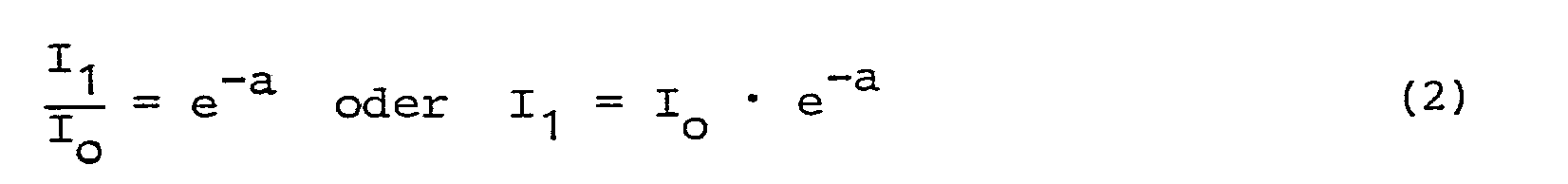


Dabei bedeuten:
- I1 - Empfangenes Licht bei zweifachem Durchlaufen der Meßstrecke 11
- I2 = Empfangenes Licht bei vierfachem Durchlauf der Meßstrecke 11
- I3 = Empfangenes Licht bei sechsfachem Durchlauf der Meßstrecke 11.
- I 1 - Received light when passing through the
measurement section 11 twice - I 2 = light received when the measuring
section 11 is run four times - I 3 = light received when the measuring
section 11 is run through six times.
Indem man nun beispielweise in der elektronischen Auswerteschaltung 15 den Quotienten I3/I1 oder auch I2/I1 bildet, eliminiert man die Größe Io, welche nach den bisherigen Methoden durch den Nullpunktreflektor gewonnen werden mußte. Als eigentliche Referenz dient somit die Meßgröße I1, die von der Meßreflektoranordnung 13 mitbestimmt wird. Der Nullpunktreflektor und die Innenreferenz können damit entfallen.By forming the quotient I 3 / I 1 or I2 / I1 in the
Das Problem der homogenen Überstrahlung der Meßreflektoranordnung 13 ist nun ebenfalls nicht mehr relevant, weil für den Referenzyklus (Zweifachmeßstrecke) und den Meßzyklus (Vierfach- bzw. Sechsfachmeßstrecke) derselbe Ausschnitt der Licht-Sendekeule verwendet wird.The problem of homogeneous irradiation of the measuring reflector arrangement 13 is no longer relevant either, because the same section of the light-transmitting lobe is used for the reference cycle (double measuring section) and the measuring cycle (four-fold or six-fold measuring section).
Die Sektorenblende 27 ist erfindungsgemäß so ausgelegt, daß entweder das sechsfach oder das zweifach durch die Meßstrecke 11 gelaufende Strahlenbündel zur Lichtempfangsanordnung 14 gelangt. Je nach dem, wie schnell sich die Sektorenblende dreht, erfolgt eine mehr oder weniger schnelle Umschaltung von dem Zwei- auf den Sechsfachstrahlengang und umgekehrt.The sector diaphragm 27 is designed according to the invention in such a way that either the six-fold or the twice-through the measuring
Der wesentliche Vorteil des erfindungsgemäßen Systems besteht darin, daß für den Zweifach- und den Sechsfachstrahlengang immer der gleiche Lichtausschnitt aus der Sendekeule durch den Reflektor 13 ausgenützt wird. Aus diesem Grunde ist die Homogenität innerhalb der Sendekeule nicht mehr kritisch.The main advantage of the system according to the invention is that the same light section from the transmitting lobe is always used by the reflector 13 for the double and the six-fold beam path. For this reason, the homogeneity within the transmission lobe is no longer critical.
Ein weiterer Vorteil besteht darin, daß nach diesem Verfahren ein Abgleich auf rauchfreier Strecke, der bisher den Abbau von Optikkopf und Reflektor erforderlich machte, entfallen kann.Another advantage is that this method eliminates the need for adjustment on a smoke-free route, which previously made it necessary to dismantle the optical head and reflector.
Für die Zwecke der Erfindung können auch verschiedene Strahlengänge der Anordnung nach der DE-PS 25 08 860 herangezogen werden. So kann man z.B. den Strahlengang nach Fig. 1 dieser Patentschrift verwenden, indem man hinter dem Bild 12' der Lichtquelle 12 den Photoempfänger für den Zweifach-Strahlengang anordnet. Fig. 1 der DE-PS 25 08 860 zeigt auch, wie man die Bilder 12' der Lichtquelle durch Keile 18, 18' seitlich versetzen kann.Various beam paths of the arrangement according to DE-PS 25 08 860 can also be used for the purposes of the invention. So you can e.g. use the beam path according to FIG. 1 of this patent specification by arranging the photoreceiver for the double beam path behind the image 12 'of the light source 12. Fig. 1 of DE-PS 25 08 860 also shows how the images 12 'of the light source can be laterally offset by
Claims (10)
Applications Claiming Priority (2)
| Application Number | Priority Date | Filing Date | Title |
|---|---|---|---|
| DE3309838 | 1983-03-18 | ||
| DE3309838A DE3309838C2 (en) | 1983-03-18 | 1983-03-18 | Optical transmission meter |
Publications (3)
| Publication Number | Publication Date |
|---|---|
| EP0119618A2 true EP0119618A2 (en) | 1984-09-26 |
| EP0119618A3 EP0119618A3 (en) | 1985-07-03 |
| EP0119618B1 EP0119618B1 (en) | 1987-09-09 |
Family
ID=6193924
Family Applications (1)
| Application Number | Title | Priority Date | Filing Date |
|---|---|---|---|
| EP84102951A Expired EP0119618B1 (en) | 1983-03-18 | 1984-03-16 | Optical device for the measurement of transmission |
Country Status (2)
| Country | Link |
|---|---|
| EP (1) | EP0119618B1 (en) |
| DE (2) | DE3309838C2 (en) |
Cited By (3)
| Publication number | Priority date | Publication date | Assignee | Title |
|---|---|---|---|---|
| EP0254863A2 (en) * | 1986-07-18 | 1988-02-03 | Erwin Sick GmbH Optik-Elektronik | Optical autocollimation measuring apparatus |
| GB2261502A (en) * | 1991-10-04 | 1993-05-19 | Churchill V L Ltd | Smoke detection device |
| EP0629983A1 (en) * | 1993-06-02 | 1994-12-21 | David Appleby | Obscuration type smoke detector |
Citations (4)
| Publication number | Priority date | Publication date | Assignee | Title |
|---|---|---|---|---|
| US3617756A (en) * | 1968-03-26 | 1971-11-02 | Erwin Sick | Optical measuring apparatus using measuring and comparison light beams |
| US3857641A (en) * | 1973-01-23 | 1974-12-31 | Sick Optik Elektronik Erwin | Optical measuring apparatus |
| FR2302539A1 (en) * | 1975-02-28 | 1976-09-24 | Sick Optik Elektronik Erwin | MULTIPLE OPTICAL REFLECTION ARRANGEMENT |
| GB2023873A (en) * | 1978-06-22 | 1980-01-03 | Sick Optik Elektronik Erwin | Optical multiply reflecting arrangement |
Family Cites Families (3)
| Publication number | Priority date | Publication date | Assignee | Title |
|---|---|---|---|---|
| US3588496A (en) * | 1968-12-26 | 1971-06-28 | Gen Electric | Radiation analysis apparatus having an absorption chamber with partially reflective mirror surfaces |
| DE2111394A1 (en) * | 1971-03-05 | 1972-09-14 | Auergesellschaft Gmbh | Absorption meter |
| DE2659898C3 (en) * | 1976-06-14 | 1981-02-05 | Werner Prof. Dr.-Ing. 7505 Ettlingen Adrian | Device for determining the concentration of a gas |
-
1983
- 1983-03-18 DE DE3309838A patent/DE3309838C2/en not_active Expired
-
1984
- 1984-03-16 DE DE8484102951T patent/DE3466072D1/en not_active Expired
- 1984-03-16 EP EP84102951A patent/EP0119618B1/en not_active Expired
Patent Citations (4)
| Publication number | Priority date | Publication date | Assignee | Title |
|---|---|---|---|---|
| US3617756A (en) * | 1968-03-26 | 1971-11-02 | Erwin Sick | Optical measuring apparatus using measuring and comparison light beams |
| US3857641A (en) * | 1973-01-23 | 1974-12-31 | Sick Optik Elektronik Erwin | Optical measuring apparatus |
| FR2302539A1 (en) * | 1975-02-28 | 1976-09-24 | Sick Optik Elektronik Erwin | MULTIPLE OPTICAL REFLECTION ARRANGEMENT |
| GB2023873A (en) * | 1978-06-22 | 1980-01-03 | Sick Optik Elektronik Erwin | Optical multiply reflecting arrangement |
Cited By (4)
| Publication number | Priority date | Publication date | Assignee | Title |
|---|---|---|---|---|
| EP0254863A2 (en) * | 1986-07-18 | 1988-02-03 | Erwin Sick GmbH Optik-Elektronik | Optical autocollimation measuring apparatus |
| EP0254863A3 (en) * | 1986-07-18 | 1989-09-06 | Erwin Sick GmbH Optik-Elektronik | Optical autocollimation measuring apparatus |
| GB2261502A (en) * | 1991-10-04 | 1993-05-19 | Churchill V L Ltd | Smoke detection device |
| EP0629983A1 (en) * | 1993-06-02 | 1994-12-21 | David Appleby | Obscuration type smoke detector |
Also Published As
| Publication number | Publication date |
|---|---|
| EP0119618A3 (en) | 1985-07-03 |
| DE3309838C2 (en) | 1986-06-05 |
| EP0119618B1 (en) | 1987-09-09 |
| DE3309838A1 (en) | 1984-09-20 |
| DE3466072D1 (en) | 1987-10-15 |
Similar Documents
| Publication | Publication Date | Title |
|---|---|---|
| DE2508366C3 (en) | Optical device with a light curtain | |
| DE2905630C2 (en) | Optical measuring device | |
| EP0156181B1 (en) | Optical system for the simultaneous reception of thermal and laser radiation | |
| EP0181388B1 (en) | Optoelectric distance measuring apparatus with an optical measuring probe | |
| EP0304805B1 (en) | Optical scanning apparatus for a transparent web of material | |
| DE2532603C3 (en) | Optical device for determining the light exit angle | |
| EP0145877B1 (en) | Photometer for continuous analysis of a medium (gas or liquid) | |
| DE2827704A1 (en) | DEVICE FOR DETECTING FAULTS ON RAILWAY MATERIAL | |
| DE3000352C2 (en) | Optoelectronic monitoring device | |
| DE2448651A1 (en) | Wire diameter contactless measuring device - is for the dimensional metrology of wires in a drawing plant | |
| DE3446355A1 (en) | OPTICAL TROUBLESHOOTING DEVICE | |
| DE10146639A1 (en) | Light grid with beam splitter | |
| CH669844A5 (en) | ||
| DE4004530A1 (en) | Optical distance measuring appts. - has light transmitters and receivers forming transducer pairs | |
| DE2827705C3 (en) | Device for the detection of defects in web material | |
| DE3401475C2 (en) | ||
| EP0119618B1 (en) | Optical device for the measurement of transmission | |
| DE1950568C3 (en) | Device for the detection of defects in transparent objects | |
| DE3405886A1 (en) | Method and device for the polarimetric measurement of the rolling angle of a movable machine part | |
| DE2508860C3 (en) | Multiple reflection optical arrangement | |
| DE2823957C2 (en) | Optical smoke detector based on the transmission principle | |
| DE3408106A1 (en) | Optical roughness scanner | |
| DE3320894A1 (en) | Optical measurement quantity pick-up | |
| DE10106075C2 (en) | Concentric light sensor | |
| DE2405412A1 (en) | OPTICAL SYSTEM FOR MEASURING DISTANCES OR SPEEDS |
Legal Events
| Date | Code | Title | Description |
|---|---|---|---|
| PUAI | Public reference made under article 153(3) epc to a published international application that has entered the european phase |
Free format text: ORIGINAL CODE: 0009012 |
|
| 17P | Request for examination filed |
Effective date: 19840316 |
|
| AK | Designated contracting states |
Designated state(s): DE FR GB IT NL SE |
|
| PUAL | Search report despatched |
Free format text: ORIGINAL CODE: 0009013 |
|
| AK | Designated contracting states |
Designated state(s): DE FR GB IT NL SE |
|
| 17Q | First examination report despatched |
Effective date: 19861203 |
|
| GRAA | (expected) grant |
Free format text: ORIGINAL CODE: 0009210 |
|
| AK | Designated contracting states |
Kind code of ref document: B1 Designated state(s): DE FR GB IT NL SE |
|
| ITF | It: translation for a ep patent filed |
Owner name: BARZANO' E ZANARDO MILANO S.P.A. |
|
| REF | Corresponds to: |
Ref document number: 3466072 Country of ref document: DE Date of ref document: 19871015 |
|
| GBT | Gb: translation of ep patent filed (gb section 77(6)(a)/1977) | ||
| ET | Fr: translation filed | ||
| PLBE | No opposition filed within time limit |
Free format text: ORIGINAL CODE: 0009261 |
|
| STAA | Information on the status of an ep patent application or granted ep patent |
Free format text: STATUS: NO OPPOSITION FILED WITHIN TIME LIMIT |
|
| 26N | No opposition filed | ||
| PGFP | Annual fee paid to national office [announced via postgrant information from national office to epo] |
Ref country code: FR Payment date: 19890315 Year of fee payment: 6 |
|
| PGFP | Annual fee paid to national office [announced via postgrant information from national office to epo] |
Ref country code: SE Payment date: 19890322 Year of fee payment: 6 |
|
| ITTA | It: last paid annual fee | ||
| PGFP | Annual fee paid to national office [announced via postgrant information from national office to epo] |
Ref country code: NL Payment date: 19890331 Year of fee payment: 6 |
|
| PGFP | Annual fee paid to national office [announced via postgrant information from national office to epo] |
Ref country code: GB Payment date: 19890430 Year of fee payment: 6 |
|
| PGFP | Annual fee paid to national office [announced via postgrant information from national office to epo] |
Ref country code: DE Payment date: 19890512 Year of fee payment: 6 |
|
| PG25 | Lapsed in a contracting state [announced via postgrant information from national office to epo] |
Ref country code: GB Effective date: 19900316 |
|
| PG25 | Lapsed in a contracting state [announced via postgrant information from national office to epo] |
Ref country code: SE Effective date: 19900317 |
|
| PG25 | Lapsed in a contracting state [announced via postgrant information from national office to epo] |
Ref country code: NL Effective date: 19901001 |
|
| GBPC | Gb: european patent ceased through non-payment of renewal fee | ||
| NLV4 | Nl: lapsed or anulled due to non-payment of the annual fee | ||
| PG25 | Lapsed in a contracting state [announced via postgrant information from national office to epo] |
Ref country code: FR Effective date: 19901130 |
|
| PG25 | Lapsed in a contracting state [announced via postgrant information from national office to epo] |
Ref country code: DE Effective date: 19901201 |
|
| REG | Reference to a national code |
Ref country code: FR Ref legal event code: ST |
|
| EUG | Se: european patent has lapsed |
Ref document number: 84102951.5 Effective date: 19910110 |