EP0117669A1 - Producing thermoplastic articles, particularly with porous walls - Google Patents
Producing thermoplastic articles, particularly with porous walls Download PDFInfo
- Publication number
- EP0117669A1 EP0117669A1 EP84300798A EP84300798A EP0117669A1 EP 0117669 A1 EP0117669 A1 EP 0117669A1 EP 84300798 A EP84300798 A EP 84300798A EP 84300798 A EP84300798 A EP 84300798A EP 0117669 A1 EP0117669 A1 EP 0117669A1
- Authority
- EP
- European Patent Office
- Prior art keywords
- pipe
- spindles
- article
- expander
- filler
- Prior art date
- Legal status (The legal status is an assumption and is not a legal conclusion. Google has not performed a legal analysis and makes no representation as to the accuracy of the status listed.)
- Granted
Links
- 229920001169 thermoplastic Polymers 0.000 title claims abstract description 13
- 239000004416 thermosoftening plastic Substances 0.000 title claims abstract description 13
- 239000000945 filler Substances 0.000 claims abstract description 19
- 239000011159 matrix material Substances 0.000 claims abstract description 17
- 239000012815 thermoplastic material Substances 0.000 claims abstract description 11
- 239000002245 particle Substances 0.000 claims abstract description 7
- 238000004519 manufacturing process Methods 0.000 claims description 5
- 238000000034 method Methods 0.000 claims description 5
- 238000000465 moulding Methods 0.000 claims description 4
- 230000002745 absorbent Effects 0.000 claims description 2
- 239000002250 absorbent Substances 0.000 claims description 2
- 238000010438 heat treatment Methods 0.000 claims description 2
- XLYOFNOQVPJJNP-UHFFFAOYSA-N water Substances O XLYOFNOQVPJJNP-UHFFFAOYSA-N 0.000 claims description 2
- 238000001816 cooling Methods 0.000 claims 1
- 239000000463 material Substances 0.000 abstract description 9
- 238000011144 upstream manufacturing Methods 0.000 description 5
- 239000002689 soil Substances 0.000 description 4
- 230000002262 irrigation Effects 0.000 description 2
- 238000003973 irrigation Methods 0.000 description 2
- 238000005096 rolling process Methods 0.000 description 2
- 230000015572 biosynthetic process Effects 0.000 description 1
- 230000000694 effects Effects 0.000 description 1
- 238000001125 extrusion Methods 0.000 description 1
- 239000004744 fabric Substances 0.000 description 1
- 229910052500 inorganic mineral Inorganic materials 0.000 description 1
- 239000007788 liquid Substances 0.000 description 1
- 239000002184 metal Substances 0.000 description 1
- 239000011707 mineral Substances 0.000 description 1
- 230000002093 peripheral effect Effects 0.000 description 1
- 239000000843 powder Substances 0.000 description 1
- 230000000284 resting effect Effects 0.000 description 1
Images


Classifications
-
- B—PERFORMING OPERATIONS; TRANSPORTING
- B29—WORKING OF PLASTICS; WORKING OF SUBSTANCES IN A PLASTIC STATE IN GENERAL
- B29C—SHAPING OR JOINING OF PLASTICS; SHAPING OF MATERIAL IN A PLASTIC STATE, NOT OTHERWISE PROVIDED FOR; AFTER-TREATMENT OF THE SHAPED PRODUCTS, e.g. REPAIRING
- B29C67/00—Shaping techniques not covered by groups B29C39/00 - B29C65/00, B29C70/00 or B29C73/00
- B29C67/20—Shaping techniques not covered by groups B29C39/00 - B29C65/00, B29C70/00 or B29C73/00 for porous or cellular articles, e.g. of foam plastics, coarse-pored
-
- B—PERFORMING OPERATIONS; TRANSPORTING
- B29—WORKING OF PLASTICS; WORKING OF SUBSTANCES IN A PLASTIC STATE IN GENERAL
- B29C—SHAPING OR JOINING OF PLASTICS; SHAPING OF MATERIAL IN A PLASTIC STATE, NOT OTHERWISE PROVIDED FOR; AFTER-TREATMENT OF THE SHAPED PRODUCTS, e.g. REPAIRING
- B29C55/00—Shaping by stretching, e.g. drawing through a die; Apparatus therefor
-
- B—PERFORMING OPERATIONS; TRANSPORTING
- B29—WORKING OF PLASTICS; WORKING OF SUBSTANCES IN A PLASTIC STATE IN GENERAL
- B29C—SHAPING OR JOINING OF PLASTICS; SHAPING OF MATERIAL IN A PLASTIC STATE, NOT OTHERWISE PROVIDED FOR; AFTER-TREATMENT OF THE SHAPED PRODUCTS, e.g. REPAIRING
- B29C53/00—Shaping by bending, folding, twisting, straightening or flattening; Apparatus therefor
- B29C53/22—Corrugating
- B29C53/30—Corrugating of tubes
-
- B—PERFORMING OPERATIONS; TRANSPORTING
- B29—WORKING OF PLASTICS; WORKING OF SUBSTANCES IN A PLASTIC STATE IN GENERAL
- B29C—SHAPING OR JOINING OF PLASTICS; SHAPING OF MATERIAL IN A PLASTIC STATE, NOT OTHERWISE PROVIDED FOR; AFTER-TREATMENT OF THE SHAPED PRODUCTS, e.g. REPAIRING
- B29C55/00—Shaping by stretching, e.g. drawing through a die; Apparatus therefor
- B29C55/22—Shaping by stretching, e.g. drawing through a die; Apparatus therefor of tubes
- B29C55/24—Shaping by stretching, e.g. drawing through a die; Apparatus therefor of tubes radial
-
- B—PERFORMING OPERATIONS; TRANSPORTING
- B29—WORKING OF PLASTICS; WORKING OF SUBSTANCES IN A PLASTIC STATE IN GENERAL
- B29K—INDEXING SCHEME ASSOCIATED WITH SUBCLASSES B29B, B29C OR B29D, RELATING TO MOULDING MATERIALS OR TO MATERIALS FOR MOULDS, REINFORCEMENTS, FILLERS OR PREFORMED PARTS, e.g. INSERTS
- B29K2105/00—Condition, form or state of moulded material or of the material to be shaped
- B29K2105/04—Condition, form or state of moulded material or of the material to be shaped cellular or porous
-
- B—PERFORMING OPERATIONS; TRANSPORTING
- B29—WORKING OF PLASTICS; WORKING OF SUBSTANCES IN A PLASTIC STATE IN GENERAL
- B29K—INDEXING SCHEME ASSOCIATED WITH SUBCLASSES B29B, B29C OR B29D, RELATING TO MOULDING MATERIALS OR TO MATERIALS FOR MOULDS, REINFORCEMENTS, FILLERS OR PREFORMED PARTS, e.g. INSERTS
- B29K2105/00—Condition, form or state of moulded material or of the material to be shaped
- B29K2105/06—Condition, form or state of moulded material or of the material to be shaped containing reinforcements, fillers or inserts
- B29K2105/16—Fillers
-
- B—PERFORMING OPERATIONS; TRANSPORTING
- B29—WORKING OF PLASTICS; WORKING OF SUBSTANCES IN A PLASTIC STATE IN GENERAL
- B29L—INDEXING SCHEME ASSOCIATED WITH SUBCLASS B29C, RELATING TO PARTICULAR ARTICLES
- B29L2023/00—Tubular articles
- B29L2023/18—Pleated or corrugated hoses
Definitions
- the present invention relates to the production of porous articles from thermoplastic materials, and particularly to methods and apparatus for the production of such articles and articles produced thereby.
- Porous thermoplastic articles have a variety of uses, for example, it is common in soil irrigation and drainage to use perforated corrugated thermoplastic pipe.
- the perforations in the pipe allow water to percolate in to or out of the pipe as necessary.
- the corrugations give the pipe radial rigidity.
- the perforations are cut, sawn or drilled holes that can become clogged with soil and other foreign material. Soil can enter the pipe through the perforations. Attempts to solve these problems have lead to the use of fabric filter sleeves around perforated pipe and the use of ever smaller perforations.
- the present invention concerns the provision of novel forms of porous article, especially pipe, and methods and apparatus for their production. While the invention has particular applicability to thermoplastic pipe that maybe used in soil irrigation and drainage; it is to be understood that it has general applicability to porous thermoplastic articles.
- the present invention provides a method of making a porous article comprising molding the article of a thermoplastic material having a particulate filler distributed therein and expanding the article to form fissures between the thermoplastic material and particles of the filler.
- the expansion of the article, after its formation, will separate the thermoplastic matrix from the particles of filler material to form fissures in the article.
- the fissures make the article porous. They may, if small, act as capilliary passages through a wall so that liquids can seep through the article, for example into and out of a pipe. Larger fissures will permit a more rapid flow.
- the article may be cooled after molding to set the thermoplastic matrix and then heated before expansion to bring the thermoplastic to a desired temperature for expansion.
- filler materials may be used. For example, minerals, metal powders or even absorbent material such as sawdust may be employed.
- the filler should be selected such that any bonds formed between the matrix and the filler are weaker in tension than the matrix material under the conditions prevailing during expansion.
- the present invention provides a porous article comprising a matrix of thermoplastic material, a particulate filler material distributed in the matrix and fissures in the matrix adjacent particles of the filler.
- the article may be a pipe, particularly a corrugated pipe such as those used for drainage.
- the present invention provides an expander for enlarging a pipe as it is advanced along a feed path, said expander comprising a plurality of spindles adapted to be located within the pipe with the spindles diverging in a downstream direction and drive means for revolving the spindles about the axis of the pipe.
- each spindle may have a ribbed outer surface for engaging the pipe corrugations.
- Means may be provided for rotating the spindles about their axes to advance the pipe along its feed path.
- the invention provides an expander comprising a set of inner spindles with transversely ribbed surfaces, a set of outer spindles with transversely ribbed surfaces, means mounting the inner spindles for passage of a pipe thereover, means mounting the outer spindles opposite the inner spindles for passage of the pipe therebetween, and means for revolving the spindles about the pipe.
- the spindle ribs may increase in depth from an upstream end to a downstream end so that when the pipe is passed between the inner and outer spindles the corrugations are deepened, thus expanding their sides. This yields porous corrugation sides and impervious or less porous corrugation crests and bases.
- An apparatus of this type can also be used for rolling a corrugated profile into a smooth pipe.
- the apparatus may include a pipe producing means, a cooler for setting the pipe after it has been produced and a heater for heating the cooled pipe before it is expanded.
- the pipe producing means may differ depending on the pipe to be produced.
- an extruder and a pipe molding apparatus known as a corrugator is suitable, while with smooth-walled pipe an extruder and a vacuum sizer may be used.
- thermoplastic material orients the material and increases the material strength.
- the apparatus particularly the expander, may therefore be used for orienting thermoplastic pipe as a sole effect.
- Figure 1 schematically illustrates an extruder die 8 and a corrugator 10 of known form for producing a corrugated thermoplastic pipe 12.
- An extruder die and corrugator of this type are disclosed in Lupke United States Patent 3981663, issued September 21, 1976.
- the pipe is made from a thermoplastic material matrix with a particulate filler distributed in the matrix.
- the pipe 12 passes through a cooler 14 to ensure setting of the thermoplastic material. Downstream from cooler 14, the pipe is reheated in a heater 16 and then passed over an expander inside the pipe at section A.
- a pipe guide 18 may be located downstream of the expander section A.
- the corrugator 10, cooler 14, heater 16 and guide 18 are known elements and will not be described in further detail.
- a pipe 20 extends along the pipe 12 from the extrusion die 8, through the corrugator 10, the cooler 14 and the heater 16.
- An air motor 24 mounted on an end flange of the pipe by machine screws 28.
- the drive shaft 30 of the motor 24 extends through a ring gear 32 mounted on the downstream side of the flange 26.
- a spool 34 is keyed to the drive shaft 30 downstream of ring gear 32.
- Three spindles 36 are carried by the end flanges 37 and 38 of spool 34.
- the spindles are frusto-conical, widening in the downstream direction.
- the spindles also diverge in the downstream direction, as shown most particularly in Figure 2. At their upstream ends, the spindles fit into the unexpanded diameter of the pipe 12.
- Each spindle 36 carries a gear 39 at its upstream end, meshing with an idler 40 mounted on the end flange 38 of the spool 36.
- the idler 40 also meshes with the ring gear 32 so that upon rotation of the spool 36, the spindles are revolved about the axis of the pipe and rotated about their axes.
- Each spindle 36 has a helical rib 42 on its outer surface that is configured to mate with the corrugations in the tube 12.
- the motor 24 rotates the spool 34. This revolves the spindles around the inside of the pipe while the gears 39, idlers 40 and ring gear 32 rotate the spindles about their respective axes.
- the ribs on the spindle engage the corrugations of pipe 12 and draw the pipe over the expander to its large diameter end.
- the pipe is progressively expanded along the expander to its final diameter where it runs off the spindles.
- the peripheral speed of each spindle should be zero at its point of contact with the non-rotating pipe. If the spool is rotating at an angular speed W 1 and the spindle is rotating about its axis at an angular speed W 2 2 the re- required condition is: or were R is the inner radius of the pipe and r is the spindle radius at the base of the ribs.
- Figure 4 illustrates an alternative form of expander, including a set of inner spindles 42 that are cylindrical and parallel to the axis of the pipe 12.
- the inner spindles 42 are carried rotatably by a spool 44, which is rotatable on a shaft 46 extending along the axis of the pipe from the expander to the extruder.
- a second set of spindles 48 is arranged symetrically around the outside of the pipe 12 on a spindle carrier 50.
- Spindles 48 are also cylindrical and parallel to the axis of the pipe 12.
- Each of the spindles 48 is arranged opposite an inner spindle 42.
- the spindle carrier 50 is mounted on a flange 52 of an expander housing 54 by a bearing 56.
- the other end of the carrier supports idler gears 58 meshing with a stationary ring gear 60 on the housing 54.
- the adjacent ends of outer spindles 48 carry gears 62 that mesh with idlers 58.
- the gear ratio of ring gear 60 to gears 62 is a function of the diameter of the pipe 12 and the diameter of the spindles 48. The ratio is selected to ensure that the tangenitial speed of each spindle 48 is zero at its point of contact with the,pipe 12.
- the spindle carrier 50 has a sheave 64 around its centre, entraining a series of drive belts 66.
- the belts are in turn entrained about a drive sheave (not shown) driven by an electric motor (also not shown).
- the inner spindle 42 and the outer spindles 48 carry transverse ribs 68 and 70 respectively.
- the ribs on each spindle are tapered so as to increase in depth from the upstream end of the spindle to the downstream end.
- the pipe 12 passes through the expander with its corrugations meshed between the ribs 68 and 70.
- the spindles 42 and 48 are located relative to one another so as to grip the corrugations of pipe 12 between them and to increase the depth of the corrugations and thus to stretch the sides of the corrugations.
- Rotation of carrier 50 by drive belt 66 revolves the outer spindles 48 about the pipe 12, while the planetary gear train constituted by gears 58, 60 and 62 rotates the spindles about their individual axes.
- the inner spindles 42 will follow the outer ones around the pipe due to the tight meshing engagement of the ribs 68 and 70 through the pipe 12.
- the spindles 42 are adjustably mounted on the spool 44 for movement toward and away from the outer spindles 48.
- Each spindle 42 has a stub shaft 72 carried at each end by bearings 74.
- the shaft extends through a radial slot 76 in the associated one of flanges 78 of the spool 44 and a slot 80 extending at an angle to both the radial and tangential directions in an annular adjustment plate 82 resting on the outer face of flange 78.
- the plate 82 is held in place by machine screws 84 extending through respective circumferential slots in the plate and threaded into bores in the flange 78.
- the machine screws 84 are loosened, the plates 82 are turned about the axis of the pipe to move the stub shafts 72 along the slots 76. Once the spindle positions are adjusted, the machine screws 84 are tightened.
- the ribs are helical. It is also possible to use annular ribs where the pipe has helical corrugation.
Abstract
Description
- The present invention relates to the production of porous articles from thermoplastic materials, and particularly to methods and apparatus for the production of such articles and articles produced thereby.
- Porous thermoplastic articles have a variety of uses, for example, it is common in soil irrigation and drainage to use perforated corrugated thermoplastic pipe. The perforations in the pipe allow water to percolate in to or out of the pipe as necessary. The corrugations give the pipe radial rigidity. With the known pipes, the perforations are cut, sawn or drilled holes that can become clogged with soil and other foreign material. Soil can enter the pipe through the perforations. Attempts to solve these problems have lead to the use of fabric filter sleeves around perforated pipe and the use of ever smaller perforations.
- The present invention concerns the provision of novel forms of porous article, especially pipe, and methods and apparatus for their production. While the invention has particular applicability to thermoplastic pipe that maybe used in soil irrigation and drainage; it is to be understood that it has general applicability to porous thermoplastic articles.
- According to one aspect, the present invention provides a method of making a porous article comprising molding the article of a thermoplastic material having a particulate filler distributed therein and expanding the article to form fissures between the thermoplastic material and particles of the filler.
- The expansion of the article, after its formation, will separate the thermoplastic matrix from the particles of filler material to form fissures in the article.
- The fissures make the article porous. They may, if small, act as capilliary passages through a wall so that liquids can seep through the article, for example into and out of a pipe. Larger fissures will permit a more rapid flow.
- The article may be cooled after molding to set the thermoplastic matrix and then heated before expansion to bring the thermoplastic to a desired temperature for expansion.
- A wide range of filler materials may be used. For example, minerals, metal powders or even absorbent material such as sawdust may be employed. The filler should be selected such that any bonds formed between the matrix and the filler are weaker in tension than the matrix material under the conditions prevailing during expansion.
- According to another aspect, the present invention provides a porous article comprising a matrix of thermoplastic material, a particulate filler material distributed in the matrix and fissures in the matrix adjacent particles of the filler.
- The article may be a pipe, particularly a corrugated pipe such as those used for drainage.
- It is possible to provide articles with selected areas of different porosites by differential expansion of the areas in question. For example, in a corrugated pipe the sides of the corrugations may be porous while the remainder of the pipe is not.
- According to a further aspect, the present invention provides an expander for enlarging a pipe as it is advanced along a feed path, said expander comprising a plurality of spindles adapted to be located within the pipe with the spindles diverging in a downstream direction and drive means for revolving the spindles about the axis of the pipe.
- For use with corrugated pipe, each spindle may have a ribbed outer surface for engaging the pipe corrugations. Means may be provided for rotating the spindles about their axes to advance the pipe along its feed path.
- Also according to this aspect, the invention provides an expander comprising a set of inner spindles with transversely ribbed surfaces, a set of outer spindles with transversely ribbed surfaces, means mounting the inner spindles for passage of a pipe thereover, means mounting the outer spindles opposite the inner spindles for passage of the pipe therebetween, and means for revolving the spindles about the pipe.
- The spindle ribs may increase in depth from an upstream end to a downstream end so that when the pipe is passed between the inner and outer spindles the corrugations are deepened, thus expanding their sides. This yields porous corrugation sides and impervious or less porous corrugation crests and bases. An apparatus of this type can also be used for rolling a corrugated profile into a smooth pipe.
- The apparatus may include a pipe producing means, a cooler for setting the pipe after it has been produced and a heater for heating the cooled pipe before it is expanded.
- The pipe producing means may differ depending on the pipe to be produced. For corrugated pipe, an extruder and a pipe molding apparatus known as a corrugator is suitable, while with smooth-walled pipe an extruder and a vacuum sizer may be used.
- The expansion of a thermoplastic material orients the material and increases the material strength. The apparatus, particularly the expander, may therefore be used for orienting thermoplastic pipe as a sole effect.
- In the accompanying drawings, which illustrate exemplary apparatus according to the present invention:
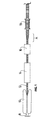
- Figure 1 is a schematic elevation illustrating an apparatus for producing a corrugated pipe;
- Figure 2 is a sectional view of a portion of the apparatus of Figure 1 taken on line 2-2 of Figure 3;
- Figure 3 is a sectional view on line 3-3 of Figure 2; and
- Figure 4 is a view like Figure 3 of another embodiment of the apparatus.
- Referring to the drawings, Figure 1 schematically illustrates an extruder die 8 and a corrugator 10 of known form for producing a corrugated
thermoplastic pipe 12. An extruder die and corrugator of this type are disclosed in Lupke United States Patent 3981663, issued September 21, 1976. - In the present case, the pipe is made from a thermoplastic material matrix with a particulate filler distributed in the matrix. After leaving the corrugator 10, the
pipe 12 passes through acooler 14 to ensure setting of the thermoplastic material. Downstream fromcooler 14, the pipe is reheated in aheater 16 and then passed over an expander inside the pipe at section A. If desired, apipe guide 18 may be located downstream of the expander section A. The corrugator 10,cooler 14,heater 16 andguide 18 are known elements and will not be described in further detail. - Passing the pipe over the expander develops fissures in the pipe between the particles of filler and the thermoplastic matrix, so that the pipe downstream of the expander is porous. The porosity of the pipe will depend on the amount and nature of the filler material and the degree of expansion.
- The expander is more clearly shown in Figures 2 and 3. A
pipe 20 extends along thepipe 12 from the extrusion die 8, through the corrugator 10, thecooler 14 and theheater 16. At the downstream end of thepipe 20 is anair motor 24 mounted on an end flange of the pipe by machine screws 28. Thedrive shaft 30 of themotor 24 extends through aring gear 32 mounted on the downstream side of the flange 26. Aspool 34 is keyed to thedrive shaft 30 downstream ofring gear 32. Threespindles 36 are carried by theend flanges spool 34. The spindles are frusto-conical, widening in the downstream direction. The spindles also diverge in the downstream direction, as shown most particularly in Figure 2. At their upstream ends, the spindles fit into the unexpanded diameter of thepipe 12. - Each
spindle 36 carries agear 39 at its upstream end, meshing with anidler 40 mounted on theend flange 38 of thespool 36. Theidler 40 also meshes with thering gear 32 so that upon rotation of thespool 36, the spindles are revolved about the axis of the pipe and rotated about their axes. - Each
spindle 36 has ahelical rib 42 on its outer surface that is configured to mate with the corrugations in thetube 12. - In operation, the
motor 24 rotates thespool 34. This revolves the spindles around the inside of the pipe while thegears 39,idlers 40 andring gear 32 rotate the spindles about their respective axes. The ribs on the spindle engage the corrugations ofpipe 12 and draw the pipe over the expander to its large diameter end. The pipe is progressively expanded along the expander to its final diameter where it runs off the spindles. - It is desirable to prevent rubbing of the spindles on the inner surface of the tube. That is, the peripheral speed of each spindle should be zero at its point of contact with the non-rotating pipe. If the spool is rotating at an angular speed W1 and the spindle is rotating about its axis at an angular speed W22 the re- required condition is:


- This can be achieved if the gear ratio of
gear 39 to ringgear 32 is equal to r R . Since the ratio of angular speeds W1 is constant, the other implication of W2 equation (2) is that the radii of the pipe and the spindle should vary in direct proportion along the pipe. This requires the spindles to diverge downstream, as well as increasing in radius, an arrangement that is illustrated in Figure 2. - Figure 4 illustrates an alternative form of expander, including a set of
inner spindles 42 that are cylindrical and parallel to the axis of thepipe 12. Theinner spindles 42 are carried rotatably by aspool 44, which is rotatable on ashaft 46 extending along the axis of the pipe from the expander to the extruder. A second set ofspindles 48 is arranged symetrically around the outside of thepipe 12 on aspindle carrier 50.Spindles 48 are also cylindrical and parallel to the axis of thepipe 12. Each of thespindles 48 is arranged opposite aninner spindle 42. - At one end, the
spindle carrier 50 is mounted on aflange 52 of anexpander housing 54 by abearing 56. The other end of the carrier supports idler gears 58 meshing with astationary ring gear 60 on thehousing 54. The adjacent ends ofouter spindles 48 carry gears 62 that mesh withidlers 58. The gear ratio ofring gear 60 togears 62 is a function of the diameter of thepipe 12 and the diameter of thespindles 48. The ratio is selected to ensure that the tangenitial speed of eachspindle 48 is zero at its point of contact with the,pipe 12. - The
spindle carrier 50 has asheave 64 around its centre, entraining a series of drive belts 66. The belts are in turn entrained about a drive sheave (not shown) driven by an electric motor (also not shown). - The
inner spindle 42 and theouter spindles 48 carrytransverse ribs pipe 12 passes through the expander with its corrugations meshed between theribs spindles pipe 12 between them and to increase the depth of the corrugations and thus to stretch the sides of the corrugations. - Rotation of
carrier 50 by drive belt 66 revolves theouter spindles 48 about thepipe 12, while the planetary gear train constituted bygears inner spindles 42 will follow the outer ones around the pipe due to the tight meshing engagement of theribs pipe 12. - In order to stretch the
pipe 12 by varying amounts in different runs, thespindles 42 are adjustably mounted on thespool 44 for movement toward and away from theouter spindles 48. Eachspindle 42 has astub shaft 72 carried at each end bybearings 74. The shaft extends through aradial slot 76 in the associated one offlanges 78 of thespool 44 and aslot 80 extending at an angle to both the radial and tangential directions in anannular adjustment plate 82 resting on the outer face offlange 78. Theplate 82 is held in place bymachine screws 84 extending through respective circumferential slots in the plate and threaded into bores in theflange 78. To adjust the position of thespindles 42, themachine screws 84 are loosened, theplates 82 are turned about the axis of the pipe to move thestub shafts 72 along theslots 76. Once the spindle positions are adjusted, themachine screws 84 are tightened. - The tapering of the ribs towards the upstream end, allows the pipe to run readily into the expander. The corrugations will gradually be deepened as they pass through the apparatus. An arrangement of this sort may also be used for rolling a corrugated profile into a smooth walled pipe.
- In the illustrated embodiments, the ribs are helical. It is also possible to use annular ribs where the pipe has helical corrugation.
Claims (15)
Priority Applications (1)
| Application Number | Priority Date | Filing Date | Title |
|---|---|---|---|
| AT84300798T ATE27569T1 (en) | 1983-02-21 | 1984-02-08 | MANUFACTURE OF THERMOPLASTIC OBJECTS, PARTICULARLY WITH POROUS WALLS. |
Applications Claiming Priority (2)
| Application Number | Priority Date | Filing Date | Title |
|---|---|---|---|
| CA422058 | 1983-02-21 | ||
| CA000422058A CA1198864A (en) | 1983-02-21 | 1983-02-21 | Producing thermoplastic articles, particularly with porous walls |
Related Child Applications (2)
| Application Number | Title | Priority Date | Filing Date |
|---|---|---|---|
| EP86200016A Division EP0182779A3 (en) | 1983-02-21 | 1984-02-08 | Expanders for enlarging pipes |
| EP86200016.3 Division-Into | 1986-01-08 |
Publications (2)
| Publication Number | Publication Date |
|---|---|
| EP0117669A1 true EP0117669A1 (en) | 1984-09-05 |
| EP0117669B1 EP0117669B1 (en) | 1987-06-03 |
Family
ID=4124604
Family Applications (2)
| Application Number | Title | Priority Date | Filing Date |
|---|---|---|---|
| EP86200016A Withdrawn EP0182779A3 (en) | 1983-02-21 | 1984-02-08 | Expanders for enlarging pipes |
| EP84300798A Expired EP0117669B1 (en) | 1983-02-21 | 1984-02-08 | Producing thermoplastic articles, particularly with porous walls |
Family Applications Before (1)
| Application Number | Title | Priority Date | Filing Date |
|---|---|---|---|
| EP86200016A Withdrawn EP0182779A3 (en) | 1983-02-21 | 1984-02-08 | Expanders for enlarging pipes |
Country Status (11)
| Country | Link |
|---|---|
| US (1) | US4553923A (en) |
| EP (2) | EP0182779A3 (en) |
| JP (1) | JPS59164121A (en) |
| KR (1) | KR860001358B1 (en) |
| AT (1) | ATE27569T1 (en) |
| AU (1) | AU557440B2 (en) |
| CA (1) | CA1198864A (en) |
| DE (1) | DE3464026D1 (en) |
| DK (1) | DK59584A (en) |
| FI (1) | FI840626A (en) |
| NO (1) | NO840623L (en) |
Cited By (2)
| Publication number | Priority date | Publication date | Assignee | Title |
|---|---|---|---|---|
| WO1995021051A1 (en) * | 1994-02-07 | 1995-08-10 | Itt Corporation | Process for producing corrugated multi-layer tubing having layers of differing plastic characteristics |
| US5960977A (en) * | 1998-05-14 | 1999-10-05 | Itt Manufacturing Enterprises, Inc. | Corrugated polymeric filler neck tubing |
Families Citing this family (11)
| Publication number | Priority date | Publication date | Assignee | Title |
|---|---|---|---|---|
| CA1303315C (en) * | 1988-09-16 | 1992-06-16 | Manfred A.A. Lupke | Apparatus for producing pipe with annular ribs |
| CA1298450C (en) * | 1988-09-16 | 1992-04-07 | Manfred A. A. Lupke | Suction applying molded blocks in pipe forming apparatus |
| MX173573B (en) * | 1989-06-19 | 1994-03-16 | Subsurface Technology Corp | IMPROVEMENTS IN POROUS TUBE AND PROCESS TO PRODUCE IT |
| GB2238976A (en) * | 1989-12-15 | 1991-06-19 | Metal Box Plc | Manufacture of thermoplastic tubular articles |
| US5531583A (en) * | 1993-04-15 | 1996-07-02 | Cullom Machine Tool & Die, Inc. | Vacuum mold blocks with cooling for corrugated tubing |
| US6240970B1 (en) | 1999-04-01 | 2001-06-05 | Itt Manufacturing Enterprises, Inc. | Tubing for handling hydrocarbon materials and having an outer jacket layer adhered thereto |
| US6276400B1 (en) | 1999-06-08 | 2001-08-21 | Itt Manufacturing Enterprises, Inc. | Corrosion resistant powder coated metal tube and process for making the same |
| US6805824B2 (en) * | 2002-03-27 | 2004-10-19 | Larry Yaw | Process for manufacturing a porous drainage medium |
| RU2332199C2 (en) * | 2002-06-03 | 2008-08-27 | Эдвансед Порес Текнолоджиз, Ллс | Ventilated closures for containers |
| WO2009011815A1 (en) * | 2007-07-13 | 2009-01-22 | Conway, Jr., William Frederick | Apparatus and method for manufacturing a consumable candy drinking straw |
| CA3053834C (en) | 2017-01-30 | 2020-09-01 | Globalmed, Inc. | Heated respiratory hose assembly |
Citations (7)
| Publication number | Priority date | Publication date | Assignee | Title |
|---|---|---|---|---|
| GB951242A (en) * | 1960-08-09 | 1964-03-04 | Illinois Tool Works | Machine and method for curling lips of container articles |
| DE1900193B2 (en) * | 1969-01-03 | 1973-05-30 | Walloschke, Ernst, 3582 Felsberg | PROCESS FOR THE MANUFACTURING OF POROUS AND FLEXIBLE DRAINAGE TUBES |
| DE1809047B2 (en) * | 1968-11-15 | 1975-12-18 | Basf Ag, 6700 Ludwigshafen | Water-permeable, coarse-pored, compact drainage elements and processes for their production |
| FR2369911A1 (en) * | 1976-11-05 | 1978-06-02 | Bommer Raymond | PROCESS FOR TULIPING THICK WALL TUBES IN FLEXIBLE PLASTIC MATERIAL, AND IMPLEMENTATION DEVICE |
| DE2812843A1 (en) * | 1977-03-25 | 1978-10-05 | Henri Delattre | DRAINAGE TAPES |
| DE2409020B2 (en) * | 1974-02-25 | 1979-02-01 | Fraenkische Isolierrohr- & Metallwaren-Werke, Gebr. Kirchner, 8729 Koenigsberg | Method and device for manufacturing thin-walled drainage pipes made of plastic |
| US4292113A (en) * | 1978-03-14 | 1981-09-29 | Toyo Kagaku Kabushiki Kaisha | Method and apparatus for manufacturing corrugated tubes |
Family Cites Families (9)
| Publication number | Priority date | Publication date | Assignee | Title |
|---|---|---|---|---|
| US2876824A (en) * | 1955-03-30 | 1959-03-10 | Goodrich Co B F | Machine for and method of progressively corrugating plastic sheet material |
| US3991150A (en) * | 1969-09-04 | 1976-11-09 | Industriele Onderneming Wavin N.V. | Method for forming a plastic pipe |
| US3857666A (en) * | 1973-04-09 | 1974-12-31 | L Barnett | Apparatus for belling ends of conduit or the like |
| GB1395192A (en) * | 1971-03-26 | 1975-05-21 | Wavin Bv | Method of and apparatus for forming an internal groove in a tubular plastics member |
| SE381001B (en) * | 1973-10-22 | 1975-11-24 | Erik G W Nordstroem | PROCEDURE AND DEVICE FOR THE MANUFACTURE OF PLASTIC CAMPLANGES |
| US3966384A (en) * | 1974-07-22 | 1976-06-29 | Maier Johann H | Machine for the thermal expansion of rigid plastic tubing |
| US3932093A (en) * | 1975-04-25 | 1976-01-13 | Maier Johann H | Tube expander apparatus |
| US4136143A (en) * | 1977-02-22 | 1979-01-23 | Lupke Gerd Paul Heinrich | Apparatus for and method of producing corrugated thermoplastic tubing |
| CA1172813A (en) * | 1982-06-16 | 1984-08-21 | Lupke, Manfred A. A. | Apparatus for producing multi-walled thermoplastic tubing |
-
1983
- 1983-02-21 CA CA000422058A patent/CA1198864A/en not_active Expired
-
1984
- 1984-01-17 AU AU23519/84A patent/AU557440B2/en not_active Ceased
- 1984-02-08 EP EP86200016A patent/EP0182779A3/en not_active Withdrawn
- 1984-02-08 DE DE8484300798T patent/DE3464026D1/en not_active Expired
- 1984-02-08 KR KR1019840000590A patent/KR860001358B1/en active
- 1984-02-08 EP EP84300798A patent/EP0117669B1/en not_active Expired
- 1984-02-08 AT AT84300798T patent/ATE27569T1/en not_active IP Right Cessation
- 1984-02-10 DK DK59584A patent/DK59584A/en not_active Application Discontinuation
- 1984-02-14 JP JP59024541A patent/JPS59164121A/en active Pending
- 1984-02-16 FI FI840626A patent/FI840626A/en not_active Application Discontinuation
- 1984-02-20 NO NO840623A patent/NO840623L/en unknown
- 1984-11-23 US US06/658,574 patent/US4553923A/en not_active Expired - Fee Related
Patent Citations (7)
| Publication number | Priority date | Publication date | Assignee | Title |
|---|---|---|---|---|
| GB951242A (en) * | 1960-08-09 | 1964-03-04 | Illinois Tool Works | Machine and method for curling lips of container articles |
| DE1809047B2 (en) * | 1968-11-15 | 1975-12-18 | Basf Ag, 6700 Ludwigshafen | Water-permeable, coarse-pored, compact drainage elements and processes for their production |
| DE1900193B2 (en) * | 1969-01-03 | 1973-05-30 | Walloschke, Ernst, 3582 Felsberg | PROCESS FOR THE MANUFACTURING OF POROUS AND FLEXIBLE DRAINAGE TUBES |
| DE2409020B2 (en) * | 1974-02-25 | 1979-02-01 | Fraenkische Isolierrohr- & Metallwaren-Werke, Gebr. Kirchner, 8729 Koenigsberg | Method and device for manufacturing thin-walled drainage pipes made of plastic |
| FR2369911A1 (en) * | 1976-11-05 | 1978-06-02 | Bommer Raymond | PROCESS FOR TULIPING THICK WALL TUBES IN FLEXIBLE PLASTIC MATERIAL, AND IMPLEMENTATION DEVICE |
| DE2812843A1 (en) * | 1977-03-25 | 1978-10-05 | Henri Delattre | DRAINAGE TAPES |
| US4292113A (en) * | 1978-03-14 | 1981-09-29 | Toyo Kagaku Kabushiki Kaisha | Method and apparatus for manufacturing corrugated tubes |
Cited By (2)
| Publication number | Priority date | Publication date | Assignee | Title |
|---|---|---|---|---|
| WO1995021051A1 (en) * | 1994-02-07 | 1995-08-10 | Itt Corporation | Process for producing corrugated multi-layer tubing having layers of differing plastic characteristics |
| US5960977A (en) * | 1998-05-14 | 1999-10-05 | Itt Manufacturing Enterprises, Inc. | Corrugated polymeric filler neck tubing |
Also Published As
| Publication number | Publication date |
|---|---|
| CA1198864A (en) | 1986-01-07 |
| AU2351984A (en) | 1984-08-30 |
| FI840626A (en) | 1984-08-22 |
| NO840623L (en) | 1984-08-22 |
| AU557440B2 (en) | 1986-12-18 |
| KR840007540A (en) | 1984-12-08 |
| DK59584D0 (en) | 1984-02-10 |
| US4553923A (en) | 1985-11-19 |
| DK59584A (en) | 1984-08-22 |
| EP0117669B1 (en) | 1987-06-03 |
| JPS59164121A (en) | 1984-09-17 |
| KR860001358B1 (en) | 1986-09-16 |
| EP0182779A2 (en) | 1986-05-28 |
| EP0182779A3 (en) | 1987-01-28 |
| ATE27569T1 (en) | 1987-06-15 |
| DE3464026D1 (en) | 1987-07-09 |
| FI840626A0 (en) | 1984-02-16 |
Similar Documents
| Publication | Publication Date | Title |
|---|---|---|
| US4553923A (en) | Producing thermoplastic articles particularly with porous walls | |
| US3824886A (en) | Apparatus for cutting apertures in tubes | |
| US4692197A (en) | Method for manufacturing corrugated tubes | |
| US3387069A (en) | Method for the manufacture of tube profiles from thermoplastics | |
| CA1186211A (en) | Apparatus for cutting openings in pipes | |
| PT100874B (en) | MACHINE AND PROCESS OF EXTRUSION FOR OBTAINING FINAL SHEETS NOT UNIFORMS | |
| US3656331A (en) | Apparatus for producing annular corrugated tubing | |
| US4636162A (en) | Apparatus for making a tubular sheath of plastic material | |
| US4158534A (en) | Apparatus for cutting openings at arbitrarily selectable intervals into pipes | |
| US3826306A (en) | Apparatus having one or more rotatably driven components | |
| WO1989005723A1 (en) | A pipe-forming machine | |
| GB1442786A (en) | Method for the production of pipe bends of thermoplastic material and apparatus for carrying out the method | |
| US4292014A (en) | Feed mechanism comprising an endless member configured as a double helix | |
| CA2127810C (en) | Corrugated pipe manufacturing apparatus | |
| US4587874A (en) | Rotary punch | |
| US4541793A (en) | Extruder nozzle and a method for producing plastic products | |
| RU2192351C2 (en) | Method and device for manufacture of extruded article and extruded article | |
| CA1108816A (en) | Method and apparatus for producing double-walled thermoplastic pipe | |
| US3703116A (en) | Method and apparatus for slitting sheet material | |
| EP0119345A1 (en) | Screening apparatus for paper making stock | |
| KR100306896B1 (en) | Double Wall Spiral Tube Forming Machine | |
| US3895992A (en) | Apparatus for manufacturing foamed plastic | |
| KR900011344Y1 (en) | Manufacturing apparatus of corrugated tube | |
| KR910000881Y1 (en) | Method for the production of sprial tube | |
| JPS6140503Y2 (en) |
Legal Events
| Date | Code | Title | Description |
|---|---|---|---|
| PUAI | Public reference made under article 153(3) epc to a published international application that has entered the european phase |
Free format text: ORIGINAL CODE: 0009012 |
|
| AK | Designated contracting states |
Designated state(s): AT BE CH DE FR GB IT LI LU NL SE |
|
| 17P | Request for examination filed |
Effective date: 19850122 |
|
| GRAA | (expected) grant |
Free format text: ORIGINAL CODE: 0009210 |
|
| ITF | It: translation for a ep patent filed |
Owner name: GUZZI E RAVIZZA S.R.L. |
|
| AK | Designated contracting states |
Kind code of ref document: B1 Designated state(s): AT BE CH DE FR GB IT LI LU NL SE |
|
| PG25 | Lapsed in a contracting state [announced via postgrant information from national office to epo] |
Ref country code: LI Effective date: 19870603 Ref country code: CH Effective date: 19870603 Ref country code: BE Effective date: 19870603 |
|
| REF | Corresponds to: |
Ref document number: 27569 Country of ref document: AT Date of ref document: 19870615 Kind code of ref document: T |
|
| REF | Corresponds to: |
Ref document number: 3464026 Country of ref document: DE Date of ref document: 19870709 |
|
| ET | Fr: translation filed | ||
| REG | Reference to a national code |
Ref country code: CH Ref legal event code: PL |
|
| PG25 | Lapsed in a contracting state [announced via postgrant information from national office to epo] |
Ref country code: LU Free format text: LAPSE BECAUSE OF NON-PAYMENT OF DUE FEES Effective date: 19880229 |
|
| PLBE | No opposition filed within time limit |
Free format text: ORIGINAL CODE: 0009261 |
|
| STAA | Information on the status of an ep patent application or granted ep patent |
Free format text: STATUS: NO OPPOSITION FILED WITHIN TIME LIMIT |
|
| 26N | No opposition filed | ||
| PGFP | Annual fee paid to national office [announced via postgrant information from national office to epo] |
Ref country code: FR Payment date: 19890117 Year of fee payment: 6 |
|
| PGFP | Annual fee paid to national office [announced via postgrant information from national office to epo] |
Ref country code: AT Payment date: 19890227 Year of fee payment: 6 |
|
| ITTA | It: last paid annual fee | ||
| PGFP | Annual fee paid to national office [announced via postgrant information from national office to epo] |
Ref country code: SE Payment date: 19890228 Year of fee payment: 6 Ref country code: NL Payment date: 19890228 Year of fee payment: 6 |
|
| PG25 | Lapsed in a contracting state [announced via postgrant information from national office to epo] |
Ref country code: AT Effective date: 19900208 |
|
| PG25 | Lapsed in a contracting state [announced via postgrant information from national office to epo] |
Ref country code: SE Effective date: 19900209 |
|
| PG25 | Lapsed in a contracting state [announced via postgrant information from national office to epo] |
Ref country code: NL Effective date: 19900901 |
|
| NLV4 | Nl: lapsed or anulled due to non-payment of the annual fee | ||
| PG25 | Lapsed in a contracting state [announced via postgrant information from national office to epo] |
Ref country code: FR Effective date: 19901031 |
|
| REG | Reference to a national code |
Ref country code: FR Ref legal event code: ST |
|
| PGFP | Annual fee paid to national office [announced via postgrant information from national office to epo] |
Ref country code: GB Payment date: 19910129 Year of fee payment: 8 |
|
| PG25 | Lapsed in a contracting state [announced via postgrant information from national office to epo] |
Ref country code: GB Effective date: 19920208 |
|
| GBPC | Gb: european patent ceased through non-payment of renewal fee | ||
| EUG | Se: european patent has lapsed |
Ref document number: 84300798.0 Effective date: 19901107 |
|
| PGFP | Annual fee paid to national office [announced via postgrant information from national office to epo] |
Ref country code: DE Payment date: 20000222 Year of fee payment: 17 |
|
| PG25 | Lapsed in a contracting state [announced via postgrant information from national office to epo] |
Ref country code: DE Free format text: LAPSE BECAUSE OF NON-PAYMENT OF DUE FEES Effective date: 20011201 |