EP0116486A1 - Electronic controller of the application of electric power to a temperature variation device - Google Patents
Electronic controller of the application of electric power to a temperature variation device Download PDFInfo
- Publication number
- EP0116486A1 EP0116486A1 EP84400028A EP84400028A EP0116486A1 EP 0116486 A1 EP0116486 A1 EP 0116486A1 EP 84400028 A EP84400028 A EP 84400028A EP 84400028 A EP84400028 A EP 84400028A EP 0116486 A1 EP0116486 A1 EP 0116486A1
- Authority
- EP
- European Patent Office
- Prior art keywords
- temperature
- electronic controller
- detector
- controller according
- memory
- Prior art date
- Legal status (The legal status is an assumption and is not a legal conclusion. Google has not performed a legal analysis and makes no representation as to the accuracy of the status listed.)
- Granted
Links
- 230000033001 locomotion Effects 0.000 claims abstract description 63
- 230000006870 function Effects 0.000 claims abstract description 14
- 238000001514 detection method Methods 0.000 claims description 19
- 230000033228 biological regulation Effects 0.000 claims description 6
- 238000004378 air conditioning Methods 0.000 claims description 5
- 230000008859 change Effects 0.000 claims description 4
- 238000009423 ventilation Methods 0.000 claims description 4
- 230000001360 synchronised effect Effects 0.000 claims 1
- 238000010438 heat treatment Methods 0.000 abstract description 19
- 230000001105 regulatory effect Effects 0.000 abstract description 6
- 230000035945 sensitivity Effects 0.000 abstract description 6
- 230000001276 controlling effect Effects 0.000 abstract description 2
- 230000001419 dependent effect Effects 0.000 abstract description 2
- 238000012545 processing Methods 0.000 description 61
- 230000007704 transition Effects 0.000 description 9
- 238000010586 diagram Methods 0.000 description 8
- 238000005070 sampling Methods 0.000 description 7
- 238000004364 calculation method Methods 0.000 description 5
- 230000003321 amplification Effects 0.000 description 4
- 238000000034 method Methods 0.000 description 4
- 238000003199 nucleic acid amplification method Methods 0.000 description 4
- 230000005540 biological transmission Effects 0.000 description 2
- 238000012937 correction Methods 0.000 description 2
- 238000002955 isolation Methods 0.000 description 2
- 239000004065 semiconductor Substances 0.000 description 2
- 230000006641 stabilisation Effects 0.000 description 2
- 238000011105 stabilization Methods 0.000 description 2
- 238000012360 testing method Methods 0.000 description 2
- 230000008542 thermal sensitivity Effects 0.000 description 2
- 238000006677 Appel reaction Methods 0.000 description 1
- 235000016068 Berberis vulgaris Nutrition 0.000 description 1
- 241000335053 Beta vulgaris Species 0.000 description 1
- 241001415961 Gaviidae Species 0.000 description 1
- 230000009471 action Effects 0.000 description 1
- 230000003213 activating effect Effects 0.000 description 1
- 238000004458 analytical method Methods 0.000 description 1
- 230000008901 benefit Effects 0.000 description 1
- 230000002457 bidirectional effect Effects 0.000 description 1
- 239000013078 crystal Substances 0.000 description 1
- 230000002950 deficient Effects 0.000 description 1
- 238000013461 design Methods 0.000 description 1
- 230000000694 effects Effects 0.000 description 1
- 238000005265 energy consumption Methods 0.000 description 1
- 238000005516 engineering process Methods 0.000 description 1
- 238000000605 extraction Methods 0.000 description 1
- 238000009434 installation Methods 0.000 description 1
- 239000004973 liquid crystal related substance Substances 0.000 description 1
- 238000004519 manufacturing process Methods 0.000 description 1
- 239000000463 material Substances 0.000 description 1
- 229910052751 metal Inorganic materials 0.000 description 1
- 239000002184 metal Substances 0.000 description 1
- 150000002739 metals Chemical class 0.000 description 1
- 238000012986 modification Methods 0.000 description 1
- 230000004048 modification Effects 0.000 description 1
- 230000010355 oscillation Effects 0.000 description 1
- 230000002688 persistence Effects 0.000 description 1
- 230000004044 response Effects 0.000 description 1
- 230000002207 retinal effect Effects 0.000 description 1
- XLYOFNOQVPJJNP-UHFFFAOYSA-N water Substances O XLYOFNOQVPJJNP-UHFFFAOYSA-N 0.000 description 1
Images


Classifications
-
- G—PHYSICS
- G05—CONTROLLING; REGULATING
- G05D—SYSTEMS FOR CONTROLLING OR REGULATING NON-ELECTRIC VARIABLES
- G05D23/00—Control of temperature
- G05D23/19—Control of temperature characterised by the use of electric means
- G05D23/1902—Control of temperature characterised by the use of electric means characterised by the use of a variable reference value
-
- F—MECHANICAL ENGINEERING; LIGHTING; HEATING; WEAPONS; BLASTING
- F24—HEATING; RANGES; VENTILATING
- F24D—DOMESTIC- OR SPACE-HEATING SYSTEMS, e.g. CENTRAL HEATING SYSTEMS; DOMESTIC HOT-WATER SUPPLY SYSTEMS; ELEMENTS OR COMPONENTS THEREFOR
- F24D19/00—Details
- F24D19/10—Arrangement or mounting of control or safety devices
- F24D19/1006—Arrangement or mounting of control or safety devices for water heating systems
- F24D19/1009—Arrangement or mounting of control or safety devices for water heating systems for central heating
-
- F—MECHANICAL ENGINEERING; LIGHTING; HEATING; WEAPONS; BLASTING
- F24—HEATING; RANGES; VENTILATING
- F24D—DOMESTIC- OR SPACE-HEATING SYSTEMS, e.g. CENTRAL HEATING SYSTEMS; DOMESTIC HOT-WATER SUPPLY SYSTEMS; ELEMENTS OR COMPONENTS THEREFOR
- F24D19/00—Details
- F24D19/10—Arrangement or mounting of control or safety devices
- F24D19/1096—Arrangement or mounting of control or safety devices for electric heating systems
-
- G—PHYSICS
- G05—CONTROLLING; REGULATING
- G05D—SYSTEMS FOR CONTROLLING OR REGULATING NON-ELECTRIC VARIABLES
- G05D23/00—Control of temperature
- G05D23/19—Control of temperature characterised by the use of electric means
- G05D23/1917—Control of temperature characterised by the use of electric means using digital means
Definitions
- the present invention relates to an automatic control system for the heating installation in a residential environment.
- An electronic controller makes it possible to automatically regulate the temperature in each room of the residence according to whether said room is occupied or not and / or lit or not.
- thermostat Welker al US Patent 2,873,368 These thermostats, placed in the various rooms of the residence have a limited thermal sensitivity.
- Another method of thermal regulation sometimes suggested is to lower the preset temperature of the thermostat before the user leaves his residence and to restore the nominal temperature as soon as the user returns to his residence.
- Such a method in fact saves on heating energy.
- it has the disadvantage of not being automatic.
- the user is reluctant to use this method because he prefers to enter his residence when it is already warmed up to the nominal temperature.
- the disadvantages described above can be overcome by using an electronic temperature detector and an electronic temperature regulator which allow increased thermal sensitivity and thermal stability, thus ensuring better comfort for the user.
- a motion detector and a light detector are arranged in the various rooms of the residence so as to be able to save on heating energy when said detectors detect neither movement nor light. In this way, the thermal regulation is carried out automatically without the need to adjust the temperature during the entire period of use of the heating system.
- a microcomputer ensures rapid adjustment and stabilization at new temperatures by means of a proportional-integral-differential type control, which determines the average heating power of the heating elements in the room of the residence.
- the invention allows a highly sensitive temperature control system, automated, quickly stabilized and having a definite advantage from the point of view of energy consumption.
- the microcomputer regulates the temperature to the preset values by means of a proportional-integral-differential type controller, which provides control signals as a function of the preset temperatures and the ambient temperature of the room in the residence. signals control the average heating power of the heating elements in the room of the residence.
- the problem to be solved by the present invention consists in designing an electronic temperature controller which on the one hand is provided with better stability and better temperature sensitivity and is designed to operate at predetermined temperature regimes while depending of the presence of occupants and / or the presence of lighting in each room of the residence and which on the other hand allows to regulate the tempé erasing automatically and saving heating energy when the rooms in the residence are unoccupied and / or unlit.
- Such an electronic controller can also be used as an electronic thermometer, alarm system, fire detector or can control any energy device such as a ventilation system, air conditioning, or humidity control during a change in the occupation of the room or in the lighting of the room.
- a light detector 3 which transmits to said digital processing unit 2 the state of lighting of the room.
- a temperature detector 4 which transmits to said digital processing unit 2 the reading of the ambient temperature.
- the state of the system represents the one of the following four possibilities: presence of movement12 in the room and lighting 13 of the room, T1, absence of movement 14 in the room and lighting 13 of the room, T2, presence of movement 12 in the room and darkness 15 of the room , T3, and lack of movement14 in the room and darkness of the room, T4.
- An emergency power supply unit 6 which maintains the preselected temperature values in the memory of the digital processing unit 2 in the event of a mains power failure 56.
- a main power unit 8 which makes it possible to obtain the regulated voltages from the AC power source of the sector 56 in order to power the amplifiers and the digital circuits used or other types of circuit (to all the units 57).
- a zero detector 7 of the mains supply 56 which makes it possible to build a time base for the digital processing unit 2, said time base being used to build the various counters used in the within the digital processing unit 2.
- module "1" located on a wall of the room
- module "2” located on the radiator cover plate
- the motion detector 16 operating on the principle of the Doppler effect, on the principle of variations in the standing wave ratio of waves emitted by an antenna, on the principle of infrared detection, on the principle of photoelectric cells, or on the principle of activating a relay, and which supplies the digital processing unit 2 with binary information relating to the presence or absence of movement in the room.
- the motion detector unit 1 comprises a motion detector 16 using an electromagnetic or ultrasonic emission source and provided with an adjustable transmission power.
- the output signal corresponding to the presence or absence of movement in the room of the residence passes through an amplifier 17 of adjustable gain and through an adjustable threshold detector VS and VT, which determine the sensitivity of the detection system, the threshold detector 18 controlling a flip-flop whose binary output state represents the state of occupation of the room, said binary state being routed to the digital processing unit 2.
- the amplification can be a digital amplification.
- the adjustable digital levels of said thresholds can be determined by potentiometers, the voltage readings of which pass through an analog-digital converter.
- digital processing unit can also be stored in the digital processing unit, a control of additional digital increments on the control panel being able to vary said digital levels which are compared to the digital level of the output signal of the amplifier by means logic circuits, to determine the transitions of the state of the system, which trigger a flip-flop whose output levels represent the state of occupation of the room.
- digital sequence comparator circuits corresponding to successive samples of the motion detector output signal can be used to detect the transitions of the state of the system.
- a light detector 3 comprising a sensor 19 (photosensitive resistance or phototransistor) whose sensitivity is adjustable and whose electrical output signal which depends on the lighting state passes through an adjustable gain amplifier 20 and a hysteresis comparator 21 with two adjustable reference voltages VX and VY, so as to avoid oscillations in the case of Corposcuro.
- the output of the hysteresis comparator 21 is routed to the digital processing unit 2.
- FIG. 5 represents the hysteresis curve of the hysteresis comparator, the thresholds VX and VY of which determine the binary states of output 22 and 23.
- the reference voltages VX and VY may possibly be equal if, however, the reading of the lighting state or the changes in the set points of the controller which delivers a control signal to the temperature variation device as a function of the current temperature and temperature values preset in memory are done at spaced intervals.
- a temperature detector 4 which comprises a thermal sensor 24 (thermistor, semiconductor device or the like) having a sensitivity of x mV / ° C and the output of which is connected via an isolation unit to a amplifier 25 of gain G, the output of which supplies an analog-digital converter 26 which can be incorporated in the digital processing unit 2.
- a command or control signal from the latter 27 synchronizes the transmission of digital information or data 28 from the analog-digital converter 26.
- the adjustable gain G as well as two adjustable reference voltages of the analog-digital converter 26, make it possible to determine the minimum and maximum temperatures of the controller as well that the temperature sensitivity is Gx mV / ° C, which can be translated into an appropriate number of bits / ° C.
- the control panel of the temperature control system 5 comprises two control keys 29 and 30 which determine within a rocker system 31 the selection of the state of the system as well as the desired increment, control signals 32 from the digital processing unit 2 making it possible to read these two pieces of information sequentially.
- the predetermined temperature information corresponding to the states of the system T1, T2, T3 and T4 can be adjusted by means of a potentiometer or be incremented digitally before being stored in the memory of an interface unit.
- display 33 This conveys the data 34 for selecting the current state of the system and performs decoding and amplification operations to supply the display data 35 to the display board 36.
- Control signals 32 and 37 allow the display of the preset temperatures and the state of the corresponding system on the display panel 36.
- the display panel 41 can include, for example, light-emitting diodes, or a gas or preferably liquid crystal display.
- the selection of the state of the system 38 and 39 and the corresponding temperature 40 appear on a display panel 41 in alphanumeric form, the letters or the numbers being sequentially illuminated so that the retinal persistence of the user allows continuous viewing of said letters or numbers.
- An additional indicator 42 may be mounted if the display is one of p room temperature.
- An example of simple control from the point of view of the user consists in ensuring that the temperature readings 40 are incremented as long as the user maintains his finger on the increment key 29, and the control key of selection 30 is activated, while the system state selection readings 38 and 39 are represented each time the user selects the selection control key 30.
- the latter may order the successive display of 40, 38, 39 and 40, 38, 39, 40 and 42, 42 or even no display.
- selection control key 30 remains pressed indefinitely, it is possible to provide automatic return to the display of the ambient temperature after a period of time fixed in advance.
- increment control key 29 is pressed without the selection control key 30 being pressed, it is possible to provide the display: preset temperature corresponding to the state of the current system.
- An emergency power supply unit 6 comprising an automatic charger 43 for a battery 44, which power a second emergency regulator 45, which is used to power the memory cicuits of the digital processing unit 2.
- the battery 44 is connected to the back-up regulator 45 in the event that the mains power source 56 is absent and the main switch of the temperature control system is actuated.
- the automatic charger 43 acts so that the battery is charged when its voltage 46 drops below a first threshold and that the battery charge ceases when the battery voltage exceeds one second. d threshold.
- another threshold detector located in the emergency regulator stops supplying the memory circuits of the digital processing unit.
- An additional protection consists in preventing the battery from being discharged in the automatic charger 46, by means of a diode 47 for example.
- a digital processing unit 2 which can be made up of logic units, microprocessors, a microcomputer or a minicomputer, and which regularly compares the current temperature and the desired temperature with a view to carrying out a correction of PID type (proportional-integral-differential) of the difference between these temperatures.
- the output signal u (t) from the PID controller is a function of the input signal e (t) as follows: where the constants K, T i and T d are chosen so as to optimize the response of the temperature regulator in terms of rise time, overshoot, stabilization time and steady state.
- the digital processing unit 2 delivers a control signal which determines the number of cycles per second during which the radiator is in operation. This number of cycles can vary from 0% to 100% of a certain number of cycles of the main power source.
- the control signal of the digital processing unit can be a series of pulses which can be processed to form a series of analog modulated pulses (pulse modulation in height, pulse modulation in position or pulse modulation in duration), which is transmitted to the power control unit 10.
- the pulse modulated in duration passes through a current amplifier 50 within the module "1" 51, then is electrically transmitted to an isolation unit 52 - follower amplifier 54, or preferably an electro-optical isolator located in the power control unit 10 within the module “2" 48 and supplies the trigger of a power switch such as a relay or a semiconductor power switch - triac 55, SCR, or other - connected, in series to radiator 9, to sector 56.
- a power switch such as a relay or a semiconductor power switch - triac 55, SCR, or other - connected, in series to radiator 9, to sector 56.
- the digital processing unit uses time bases derived from a crystal oscillator and not from a zero detector 7 of sector 56
- a zero detector of the sector sector 56 in the power control unit 10 within the module "2" 48.
- the zero detector output pulses will be used to trigger a first power switch which is biased by the duration-modulated pulse from the digital processing unit 2 and the output of which is used to trigger a second power switch connected, in series to the radiator 9, to sector 56.
- Additional interface circuits are optionally added in order to make the digital processing unit 2 compatible from the point of view of transistor / CMOS technologies with the display interface unit 33, with the motion detection unit 1, the light detector 3, the temperature detector 4, the control panel 5, the zero detector 7 and the power control unit 10.
- the same power switch can activate several radiators in parallel; several radiators independent can be actuated by several power switches which are controlled by the pulse modulated in duration coming from the digital processing unit 2.
- the digital processing unit 2 can be a microcomputer having two working states, the processing state and the preselection state: in processing state, the system takes the information relating to the different detectors, and makes the necessary calculations for control the power control circuit 10.
- the microcomputer goes to the preselection state, state in which the signals routed to the power control circuit 10 are those which preexisted before the actuation of the selection control keys 30 and of incrementation 29.
- the microcomputer switches from the preselection state to the state after a specified period of time, after which all of the microcomputer timers are reset.
- the microcomputer software includes two main routines.
- the first routine performs the following operations: control of the power control unit 10, control of the motion detection unit 1, control of the light detector 3, control of the temperature detector 4, request to display new data , each of said checks being able to be sampled at times determined by appropriate counters, and calculation of the terms of the equation of the proportional-integral-differential regulator.
- the second routine performs the following operations: initialization of the working variables, initialization of a binary test value in the memory of the microcomputer in order to check the emergency power supply 6 of the microcomputer, control of the increment key 29, control of the selection key '30 and initialization of a period of time for affichage.des transistions of the system state.
- the preselected temperature values are kept in a defined portion of the memory which is supplied by the battery 44. In this way, the system can resume processing operations. However, the system will carry out a check of a test value placed in the memory of the microcomputer in order to prevent a loss of the preserved values, which can be caused by a defective beet. In such a case, the temperature control system will adjust to a determined temperature value regardless of the state of the system, until the programmable memory is updated. Said determined temperature value can be used to initialize the counters of the system when the temperature control system is activated.
- a regulating counter 59 decides the calculation times of the regulating unit 58 of the proportional, proportional-integral or proportional-integral-differential type. This counter also decides the sampling times of the ambient temperature values within the analog-digital converter associated with the temperature detector 4.
- a power meter 57 which is decremented during the duration of the pulse modulated in duration associated with the output of the regulator 58.
- f s being the frequency of the sector 56 and k a constant
- the radiator 9 will be actuated for a duration of where x can vary from 0 to 2f s .
- x can vary from 0 to 2f s .
- k (1 - 2f s ) will represent the time during which the radiator 9 is off.
- the radiator 9 is switched via the power control unit 10.
- the regulator counter 59 is subordinated to the expiration of the standby counter 60, in order to allow a calculation of the regulator on new preselected values during the transition from the preselection state to the processing state.
- the wait counter 60 is initialized when the digital processing unit changes from the preselection state to the processing state. During the transition from the processing state to the preselection state, the power counter 57 continues to operate at the value x which existed in the processing state, until the new calculation of the output values of the regulator 58 which follows the complete decrementing of the waiting counter 60.
- the sampling counter 61 of the motion detector unit 1 decides successive read times of the binary state associated with the motion detector unit 1.
- the motion counter 62 is initialized following a motion detection within a motion processing unit 63 associated with the motion detector 1.
- This motion processing unit 63 associated with the motion detection makes it possible to change by means of a pointer register 64, the temperature serving as a set point for the system, which is located in the random access memory unit 65.
- the initialization value of the movement counter 62 depends on the binary state associated with the light detector 3.
- the information of the binary state associated with the light detector 3 arrives via the motion processing unit 63 and the light sampling counter 66.
- the set point corresponding to the state of the system T 1 is maintained for a duration Y, which begins to be measured when the movement detection in the room stops.
- the corresponding set point laying in the state of the system T 3 is maintained for a period Z, which begins to be measured when the movement detection in the room stops.
- the light sampling counter 66 decides the intervals separating the successive readings from the binary state associated with the light detector 3, which readings are transmitted to the pointer register 64 which decides which of the temperature values preselected in memory 65, serves as setpoint at regulator 58.
- the display counter 67 determines when the data of the display circuits is updated.
- the display is renewed every Q seconds.
- the display is modified after a delay of R seconds in order to allow the user to observe on the display panel the changes in the system state, while pointer register 64 is updated instantly.
- the increment control button 29 When the increment control button 29 is pressed while the digital processing unit is in the processing state, the temperature serving as the current set point is displayed for a duration S.
- the control button increment 29 initiates via the rocker system 31, the display processing unit 68, and the selection processing unit 71, the extraction of the predetermined temperature serving as a set point for the regulator 58, said temperature being extracted from the RAM unit 65 via the pointer register 64 before being routed to the display unit 11.
- any action of the increment key 29 initiates a flip-flop 31 which initializes an increment ring counter 69 which, once decremented, will activate the increment unit 70.
- the increment counter 69 is reset as long as the user presses the key increment 29.
- the increment processing unit 70 updates the memory 65 and, moreover, updates the display unit 11 via the display processing unit 68 .
- the selection control key 30 When passing from the preselection state to the processing state, the selection control key 30 initiates the flip-flop 31, which initializes the waiting counter 60, and moreover transmits via the processing unit. display 68 the new ambient temperature data at the display unit 11.
- the selection control key 30 When changing from the processing state to the preselecting state, the selection control key 30 initiates the flip-flop 31 which uses the preselected values temperature stored in the memory 65 through the selection processing unit 71, the display processing unit 68, the selection processing unit 71 and the pointer register 64.
- a monostable 72 is actuated each time the selection control 30 or incrementation 29 key is actuated. At the end of the monostable output pulse, the digital processing unit returns to the processing state. This is to avoid that the system does not remain in the preselection state continuously in the event that the user forgets to return the digital processing unit to the processing state.
- the emergency power supply 6 ensures the conversation of the temperature values preselected in memory 65 in the event of a power failure 56.
- time base unit B 1 73 which can be determined directly from the alternative power source of the sector 56 by means of a Zero detector 7 of said sector power supply.
- This time base can be by example where f represents the frequency of the sector 56.
- a second time base of a second 74 (second counter) and a minute 75 (minute counter) can be deduced from the time base B 1 73.
- the following counters could be associated with the time base B,: sampling counter 61 of the motion detection unit and power counter 57.
- the time base of one second will be used by the following counters: counter display 67, regulating counter 59, incrementing counter 69.
- the one minute time base will be used by the following counters: sampling counters 66 of the light detector, movement counter 62 and standby counter 60.
- the duration of said counters can be fixed in advance in a read-only memory or even be adjusted by means of potentiometers whose output voltage level is digitally translated by means of an analog-to-digital converter.
- a detector of the transitions of the state of the system located within the digital processing unit is used to prime, defuse, or even enslave a power control circuit of the ventilation system.
- the transition detectors are electrically connected to the relay of an alarm system, said system will be activated during the transitions from T2 or T4 to T1 or T3.
- Another example would be the control of a humidifier when a transition from T4 to T3 is detected.
- the temperature controller as a fire detector. To do this, it is sufficient to check whether the ambient temperature exceeds a determined high threshold beyond a time delay.
- each state of operation comprising memorizable preselected values, so that the user can use his system in special cases such as for example that of large rooms.
- the system will offer, in addition to the normal operating state option, one or more additional options of the user's choice.
- the system described here can be used to control a central heating system of the on-off type by installing motion and / or light detectors at key locations. It can also be used to control the temperature in each room through the engine control actuating the hot water or hot air pipe valves. It can also be used to activate by means of a simple relay the ventilation or air conditioning system in the given room, the name on-off can refer to both a central heating system and a system of air conditioning; standard corrections of the humidity setting according to the temperature can be incorporated into the system in order to adjust the humidity in a residence according to the ambient temperature.
Abstract
Le domaine de l'invention est celui des dispositifs de contrôle de l'application de la puissance électrique à un dispositif de variation de température. Le problème à résoudre consiste à permettre une meilleure stabilité et une meilleure sensibilité en température et un fonctionnement à des régimes de température préétablis tout en tenant compte de la présence d'occupants et/ou de l'éclairage. A cet effet, le contrôleur comprend un capteur thermique (4) émittant un signal fonction de la température, un détecteur de mouvement (1) émettant un signal dépendant de la présence ou non de mouvement et/ou un détecteur de lumière (3) émettant un signal fonction de la luminosité, une mémoire programmable, des moyens de lui addresser un programme de températures présélectionnées tout en tenant compte desdits signaux, des moyens utilisant les informations de la mémoire pour émettre un signal représentant la température présélectionnée, mais tenant compte desdits signaux et des moyens de réception des signaux de température ambiante et de température présélectionnée, émettant au moyen d'une unité de contrôle (10) un signal de régulation du dispositif de variation de température (9). L'usage principal de l'invention est celui de la régulation des radiateurs de chauffage central.The field of the invention is that of devices for controlling the application of electric power to a temperature variation device. The problem to be solved consists in allowing better stability and better temperature sensitivity and operation at predetermined temperature regimes while taking into account the presence of occupants and / or lighting. To this end, the controller comprises a thermal sensor (4) emitting a temperature-dependent signal, a motion detector (1) emitting a signal depending on the presence or not of movement and / or a light detector (3) emitting a signal as a function of the brightness, a programmable memory, means for sending it a program of preset temperatures while taking account of said signals, means using information from the memory to emit a signal representing the preset temperature, but taking account of said signals and means for receiving the ambient temperature and preselected temperature signals, transmitting by means of a control unit (10) a signal for regulating the temperature variation device (9). The main use of the invention is that of regulating central heating radiators.
Description
La présente invention se rapporte à un système de contrôle automatique de l'installation de chauffage en milieu résidentiel. Un contrôleur électronique permet de régulariser de façon automatique la température dans chaque pièce de la résidence selon que ladite pièce est occupée ou non et/ou éclairée ou non.The present invention relates to an automatic control system for the heating installation in a residential environment. An electronic controller makes it possible to automatically regulate the temperature in each room of the residence according to whether said room is occupied or not and / or lit or not.
Les thermostats actuellement en usage en milieu résidentiel fonctionnent pour la plupart sur le principe de la dilatation thermique des métaux, comme par exemple le thermostat de Welker al le brevet U.S. 2.873.368. Ces thermostats, placés dans les différentes pièces de la résidence ont une sensibilité thermique limitée.Thermostats currently in use in residential settings work for most on the principle of thermal expansion of metals, such as thermostat Welker al US Patent 2,873,368. These thermostats, placed in the various rooms of the residence have a limited thermal sensitivity.
Certains systèmes de régulation thermique permettent de réduire la consommation d'énergie de chauffage en baissant la température durant certaines périodes de la journée lesquelles sont fixées au moyen d'une horloge mécanique ou électrique. C'est le cas, par exemple, pour les brevets canadiens de Carlson (741.463), Rudolph (1035448), Levine (1.114.474) et Wong (1117.625). Toutefois, ces systèmes n'offrent pas de flexibilité et nécessitent un réajustement chaque fois qu'il y a changement dans la régularité de l'occupation de la pièce ou de la résidence en question.Certain thermal regulation systems make it possible to reduce the consumption of heating energy by lowering the temperature during certain periods of the day which are fixed by means of a mechanical or electric clock. This is the case, for example, for the Canadian patents of Carlson (741,463), Rudolph (1035448), L evine (1,114,474) and Wong (1117,625). However, these systems do not offer flexibility and require readjustment whenever there is a change in the regularity of the occupancy of the room or residence in question.
Une autre méthode de régulation thermique parfois suggérée est de baisser la température préétablie du thermostat avant que l'utilisateur ne quitte sa résidence et de rétablir la température nominale sitôt que l'utilisateur retourne à sa résidence. Une telle méthode permet en effet d'économiser en énergie de chauffage. Toutefois elle présente l'inconvénient de ne pas être automatique. De plus, l'usager hésite à employer cette méthode, car il préfère entrer dans sa résidence alors que celle-ci est déjà réchauffée à la température nominale.Another method of thermal regulation sometimes suggested is to lower the preset temperature of the thermostat before the user leaves his residence and to restore the nominal temperature as soon as the user returns to his residence. Such a method in fact saves on heating energy. However, it has the disadvantage of not being automatic. In addition, the user is reluctant to use this method because he prefers to enter his residence when it is already warmed up to the nominal temperature.
Les inconvénients décrits plus hauts peuvent être surmontés en utilisant un détecteur de température électronique et un régulateur de température électronique lesquels permettent une sensibilité thermique et une stabilité thermique accrues, assurant ainsi un meilleur confort à l'usager. De plus, un détecteur de mouvement et un détecteur de lumière sont disposés dans les différentes pièces de la résidence de façon à pouvoir économiser en énergie de chauffage lorsque lesdits détecteurs ne décèlent ni mouvement, ni lumière. De la sorte, la régulation thermique s'effectue de façon automatique sans qu'il y ait besoin d'ajuster la température durant toute la période d'utilisation du système de chauffage. Un micro ordinateur assure un ajustement et une stabilisation rapides aux nouvelles températures au moyen d'un contrôle de type proportionnel-intégral-différentiel, lequel détermine la puissance de chauffage moyenne des éléments chauffants de la pièce de la résidence. De la sorte, l'invention permet un système de contrôle de température hautement sensible, automatisé, rapidement stabilisé et présentant un avantage certain du point de vue de la consommation énergétique. Le micro ordinateur assure la régulation de la température aux valeurs préétablies au moyen d'un contrôleur de type proportionnel-intégral-différentiel, lequel fournit des signaux de contrôle en fonction des températures préétablies et de la température ambiante de la pièce de la résidence, lesquels signaux contrôlent la puissance de chauffage moyenne des éléments chauffants de la pièce de la résidence.The disadvantages described above can be overcome by using an electronic temperature detector and an electronic temperature regulator which allow increased thermal sensitivity and thermal stability, thus ensuring better comfort for the user. In addition, a motion detector and a light detector are arranged in the various rooms of the residence so as to be able to save on heating energy when said detectors detect neither movement nor light. In this way, the thermal regulation is carried out automatically without the need to adjust the temperature during the entire period of use of the heating system. A microcomputer ensures rapid adjustment and stabilization at new temperatures by means of a proportional-integral-differential type control, which determines the average heating power of the heating elements in the room of the residence. In this way, the invention allows a highly sensitive temperature control system, automated, quickly stabilized and having a definite advantage from the point of view of energy consumption. The microcomputer regulates the temperature to the preset values by means of a proportional-integral-differential type controller, which provides control signals as a function of the preset temperatures and the ambient temperature of the room in the residence. signals control the average heating power of the heating elements in the room of the residence.
Le problème à résoudre par la présente invention consiste à concevoir un contrôleur électronique de température qui d'une part soit pourvu d'une meilleure stabilité et d'une meilleure sensibilité en température et soit conçu pour fonctionner à des régimes de températures préétablies tout en dépendant de la présence d'occupants et/ou la présence d'éclairage dans chacune des pièces de la résidence et qui d'autre part permette de régulariser la température de façon automatique et d'économiser l'énergie de chauffage lorsque les pièces de la résidence sont inoccupées et/ou non--éclairées.The problem to be solved by the present invention consists in designing an electronic temperature controller which on the one hand is provided with better stability and better temperature sensitivity and is designed to operate at predetermined temperature regimes while depending of the presence of occupants and / or the presence of lighting in each room of the residence and which on the other hand allows to regulate the tempé erasing automatically and saving heating energy when the rooms in the residence are unoccupied and / or unlit.
La présente invention a pour objet un contrôleur électronique lequel contrôle l'application de la puissance électrique à un dispositif de variation de température caractérisé en ce qu'il comprend :
- - un capteur thermique lequel génère un signal électrique dont une caractéristique varie en fonction de la température ambiante,
- - un détecteur de mouvement lequel génère un signal électrique dont une caractéristique dépend de la présence ou de l'absence de mouvement au sein de son champ de détection et/ou un détecteur de lumière lequel génère un signal électrique dont une caractéristique varie en fonction de la luminosité au sein de son champ de détection,
- - une unité de mémoire programmable,
- - des moyens d'adresser ladite mémoire avec un programme de températures présélectionnées tout dépendant de ladite ou desdites caractéristiques des signaux électriques générés par le détecteur de mouvement et/ou le détecteur de lumière,
- - des moyens de faire appel à l'information contenue dans ladite mémoire pour générer un signal électrique représentant la température présélectionnée selon lesdites caractéristiques des signaux électriques générés par le détecteur de mouvement et/ou le détecteur de lumière,
- - des moyens de recevoir les signaux électriques qui correspondent à la température ambiante et ceux qui correspondent à une température présélectionnée en mémoire et de générer au moyen d'une unité de contrôle un signal de contrôle pour le dispositif de variation de température en fonction de la différence de ces signaux électriques.
- - a thermal sensor which generates an electrical signal whose characteristic varies as a function of the ambient temperature,
- - a motion detector which generates an electrical signal, a characteristic of which depends on the presence or absence of motion within its detection field and / or a light detector which generates an electrical signal, the characteristic of which varies according to the brightness within its detection field,
- - a programmable memory unit,
- means of addressing said memory with a program of preselected temperatures all depending on said characteristic or characteristics of the electrical signals generated by the motion detector and / or the light detector,
- means for calling on the information contained in said memory to generate an electrical signal representing the preselected temperature according to said characteristics of the electrical signals generated by the motion detector and / or the light detector,
- means of receiving the electrical signals which correspond to the ambient temperature and those which correspond to a preset temperature in memory and of generating by means of a control unit a control signal for the device for varying the temperature as a function of the difference from these electrical signals.
Un tel contrôleur électronique peut également être utilisé comme thermomètre électronique, système d'alarme, détecteur de feu ou peut asservir un quelconque dispositif énergétique tel un système de ventilation, d'air climatisé, ou de réglage d'humidité lors d'un changement dans l'occupation de la pièce ou dans l'éclairage de la pièce.Such an electronic controller can also be used as an electronic thermometer, alarm system, fire detector or can control any energy device such as a ventilation system, air conditioning, or humidity control during a change in the occupation of the room or in the lighting of the room.
Relativement aux dessins qui illustrent la réalisation de l'invention,
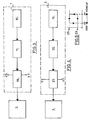
- - La figure 1 représente le schéma fonctionnel de l'ensemble du contrôleur automatique de température sensible au mouvement et à la lumière,
- - La figure 2 représente les états du système correspondant aux diverses possibilités de présence ou d'absence de mouvement et d'éclairage,
- - La figure 3 illustre le schéma fonctionnel de l'unité détectrice de mouvement,
- - La figure 4 représente le schéma fonctionnel de l'unité détectrice de lumière,
- - La figure 5 représente la courbe du comparateur hys- térisis associé à l'unité détectrice de lumière,
- - La figure 6 représente le schéma fonctionnel de l'unité détentrice de température,
- - La figure 7 représente le schéma fonctionnel du panneau de contrôle,
- - La figure 8 illustre le tableau d'affichage,
- - La figure 9 représente le schéma fonctionnel de l'unité d'alimentation de secours,
- - La figure 10 représente le schéma fonctionnnel de l'unité de contrôle de puissance du radiateur,
- - La figure 11 illustre le principe d'opération de l'unité de traitement numérique.
- FIG. 1 represents the functional diagram of the whole of the automatic temperature controller sensitive to movement and to light,
- FIG. 2 represents the states of the system corresponding to the various possibilities of presence or absence of movement and lighting,
- FIG. 3 illustrates the functional diagram of the motion detection unit,
- FIG. 4 represents the functional diagram of the light detecting unit,
- FIG. 5 represents the curve of the hysterisis comparator associated with the light detecting unit,
- FIG. 6 represents the functional diagram of the temperature holding unit,
- - Figure 7 shows the block diagram of the control panel,
- - Figure 8 illustrates the display board,
- FIG. 9 represents the functional diagram of the emergency power supply unit,
- FIG. 10 represents the functional diagram of the power control unit of the radiator,
- - Figure 11 illustrates the operating principle of the digital processing unit.
L'invention sera mieux comprise à l'aide de la description qui suit, en référence aux schémas fonctionnels représentant, à titre d'exemples non limitatifs, quelques formes de réalisation du système de contrôle de température.The invention will be better understood with the aid of the description which follows, with reference to the functional diagrams representing, by way of nonlimiting examples, some embodiments of the temperature control system.
L'invention comprend les éléments fonctionnels suivants :
- Une unité détectrice de
mouvement 1 laquelle transmet à l'unité de traitement numérique 2 l'état d'occupation de la pièce.
- A
motion detecting unit 1 which transmits to thedigital processing unit 2 the state of occupation of the room.
Un détecteur de lumière 3 lequel transmet à ladite unité de traitement numérique 2 l'état d'éclairage de la pièce.A
Un détecteur de température 4 lequel transmet à ladite unité de traitement numérique 2 la lecture de la température ambiante.A
Quatre grandeurs de température présélectionnées et ajustables, correspondant aux température désirées ,selon-l'état du système, lesquelles sont mises en mémoire dans l'unité de traitement numérique 2 à partir du panneau de contrôle 5. L'état du système représente l'une des quatre possibilités suivantes : présence de mouvement12 dans la pièce et éclairage 13 de la pièce, T1, absence de mouvement 14 dans la pièce et éclairage 13 de la pièce, T2, présence de mouvement 12 dans la pièce et obscurité 15 de la pièce, T3, et absence de mouvement14 dans la pièce et obscurité 15 de la pièce, T4.Four preset and adjustable temperature quantities, corresponding to the desired temperatures, according to the state of the system, which are stored in the
Une unité d'alimentation de secours 6 laquelle maintient les valeurs présélectionnées de température dans la mémoire de l'unité de traitement numérique 2 en cas de panne d'alimentation du secteur 56.An emergency
Une unité d'alimentation principale 8 laquelle permet d'obtenir les tensions régulées à partir de la source d'alimentation alternative du secteur 56 afin d'alimenter les amplificateurs et les circuits numériques utilisés ou d'autres types de circuit (vers toutes les unités 57).A
Un détecteur de zéro 7 de l'alimentation du secteur 56 lequel permet de construire une base de temps à l'unité de traitement numérique 2, ladite base de temps servant à construire les différents compteurs utilisés au au sein de l'unité de traitement numérique 2.A zero
Une unité de traitement numérique 2 laquelle délivre :
- - un signal de contrôle aux radiateurs électriques 9 via une unité de contrôle de puissance 10.
- - une lecture de la température ambiante et de l'état du système ainsi que les lectures des températures présélectionnées dans une unité d'affichage 11.
- - a control signal to the
electric radiators 9 via apower control unit 10. - - a reading of the ambient temperature and the state of the system as well as the readings of the preselected temperatures in a
display unit 11.
L'ensemble des éléments du système sont placés dans un premier module dit module "1", localisé sur un mur de la pièce, l'unité de contrôle de puissance de chauffage 10 des radiateurs 9 étant placée dans un second module dit module "2", situé à même la plaque de recouvrement du radiateur, et ce, afin que l'unité de contrôle de puissance 10 n'influence pas la lecture du détecteur de température. Le module "1" et le module "2" peuvent être combinés si toutefois l'unité de contrôle de puissance 10 est thermiquement isolée du capteur thermique du détecteur de température 4.All the elements of the system are placed in a first module called module "1", located on a wall of the room, the heating
a) Le détecteur de mouvement 16 fonctionnant sur le principe de l'effet Doppler, sur le principe des variations du rapport d'ondes stationnaires des ondes émises par une antenne, sur le principe de la détection infrarouge, sur le principe des cellules photoélectriques, ou sur le principe de la mise en action d'un relais, et qui fournit à l'unité de traitement numérique 2 l'information-binaire se rapportant à la présence ou l'absence de mouvement dans la pièce.a) The motion detector 16 operating on the principle of the Doppler effect, on the principle of variations in the standing wave ratio of waves emitted by an antenna, on the principle of infrared detection, on the principle of photoelectric cells, or on the principle of activating a relay, and which supplies the
L'unité détectrice d& mouvement 1 comprend un détecteur de mouvement 16 utilisant une source d'émission électromagnétique ou ultrasonique et doté d'une puissance d'émission ajustable. Le signal de sortie correspondant à la présence ou l'absence de mouvement dans la pièce de la résidence passe par un amplificateur 17 de gain ajustable et par un détecteur de seuils ajustables VS et VT, lesquels déterminent la sensibilité du système de détection, le détecteur de seuils 18 commandant une bascule dont l'état binaire de sortie représente l'état d'occupation de la pièce, ledit état binaire étant acheminé à l'unité de traitement numérique 2.The
Il est également possible de détecter l'état binaire correspondant à l'état d'occupation de la pièce de la résidence au sein même de l'unité de traitement numérique, au cas où la tension de signal de sortie du détecteur de mouvement est convertie sous forme numérique de sorte que l'amplification, la détection de seuils et la fixation de l'état du système soient faits sous forme numérique, à l'extérieur ou à l'intérieur de l'unité de traitement numérique. L'amplification peut être une amplification numérique. Les niveaux numériques ajustables desdits seuils peuvent être déterminés par des potentiomètres dont les lectures de tension passent par un convertisseur analogique-numérique. Ils peuvent également être mis en mémoire au sein de l'unité de traitement numérique, un contrôle d'incrémentations numériques supplémentaires au panneau de contrôle pouvant faire varier lesdits niveaux numériques lesquels sont comparés au niveau numérique du signal de sortie de l'amplificateur au moyens de circuits logiques, afin de déterminer les transitions de l'état du système, lesquelles déclenchent une bascule dont les niveaux de sortie représentent l'état d'occupation de la pièce. Alternativement, des circuits comparateurs de séquences numériques correspondant à des échantillons successifs du signal de sortie du détecteur de mouvement, peuvent servir à détecter les transitions de l'état du système.It is also possible to detect the binary state corresponding to the state of occupation of the room in the residence within the digital processing unit itself, in the event that the output signal voltage of the motion detector is converted in digital form so that the amplification, the detection of thresholds and the fixing of the state of the system are done in digital form, outside or inside the digital processing unit. The amplification can be a digital amplification. The adjustable digital levels of said thresholds can be determined by potentiometers, the voltage readings of which pass through an analog-digital converter. They can also be stored in the digital processing unit, a control of additional digital increments on the control panel being able to vary said digital levels which are compared to the digital level of the output signal of the amplifier by means logic circuits, to determine the transitions of the state of the system, which trigger a flip-flop whose output levels represent the state of occupation of the room. Alternatively, digital sequence comparator circuits corresponding to successive samples of the motion detector output signal can be used to detect the transitions of the state of the system.
b) Un détecteur de lumière 3 comportant un capteur 19 (résistance photosensible ou phototransistor) dont la sensibilité est ajustable et dont le signal électrique de sortie qui dépend de l'état d'éclairage passe par un amplificateur de gain ajustable 20 et un comparateur hystérésis 21 avec deux tensions de référence ajustables VX et VY, de façon à éviter des oscillations dans le cas de situation de clair-obscur. La sortie du comparateur hystérésis 21 est acheminée vers l'unité de traitement numérique 2.b) A
La figure 5 représente la courbe d'hystérésis du comparateur hystérésis, dont les seuils VX et VY déterminent les états binaires de sortie 22 et 23.FIG. 5 represents the hysteresis curve of the hysteresis comparator, the thresholds VX and VY of which determine the binary states of
Il est également possible de brancher le signal de sortie du capteur de lumière 19 à l'unité de traitement numérique 2, laquelle déterminera l'état d'éclairage de la pièce, ainsi que les changements de l'état d'éclairage selon un principe d'opérations numériques tel que décrit dans le cas de la détermination numérique de l'état d'occupation de la pièce. Les tensions de référence VX et VY peuvent être éventuellement égales si toutefois la lecture de l'état d'éclairage ou les changements de points de consigne du contrôleur lequel délivre un signal de contrôle au dispositif de variation de température en fonction de la température actuelle et des valeurs de'températures présélectionnées en mémoire, se font à des intervalles espacés.It is also possible to connect the output signal of the
c) Un détecteur de température 4 lequel comprend un capteur thermique 24 (thermistor, dispositif à se7 mi-conducteur ou autre) doté d'une sensibilité de x mV/°C et dont la sortie est connectée via une unité d'isolation à un amplificateur 25 de gain G dont la sortie alimente un convertisseur analogique numérique 26 lequel peut être incorporé dans l'unité de traitement numérique 2. Dans le cas où le convertisseur analogique-numérique 26 n'est pas incorporé à l'unité de traitement numérique 2, un signal de commande ou contrôle de cette dernière 27 synchronise la transmission de l'information numérique ou données 28 du convertisseur analogique-numérique 26. Le gain ajustable G, ainsi que deux tensions de référence ajustables du convertisseur analogique-numérique 26, permettent de déterminer les températures minimales et maximales du contrôleur, ainsi que la sensibilité en température, soit Gx mV/°C, laquelle peut être traduite en un nombre approprié de bits/°C.c) A
d) Le tableau de contrôle du système de contrôle de température 5 comprend deux touches de commande 29 et 30 lesquelles déterminent au sein d'un système de bascules 31 la sélection de l'état du système ainsi que l'in- crémentation désirée, des signaux de contrôle 32 de l'unité de traitement numérique 2 permettant de lire séquentielle- ment ces deux informations.d) The control panel of the
Les informations prédéterminées de température correspondant aux états du système T1, T2, T3 et T4 peuvent être ajustées au moyen d'un potentiomètre ou être incrémentées de façon numérique avant d'être emmagasinées dans la mémoire d'une..unité d'interface d'affichage 33. Celle-ci achemine les données 34 de sélection de l'état actuel du système et effectue des opérations de décodage et d'amplification pour alimenter les données d'affichage 35 au tableau d'affichage 36. Des signaux de contrôle 32 et 37 permettent l'affichage des températures présélectionnées et de l'état du système correspondant sur le tableau d'affichage 36.The predetermined temperature information corresponding to the states of the system T1, T2, T3 and T4 can be adjusted by means of a potentiometer or be incremented digitally before being stored in the memory of an interface unit.
e) Le tableau d'affichage 41 peut inclure par exemple des diodes luminescentes, ou un affichage à gaz ou préférablement à cristaux liquides. La sélection de l'état du système 38 et 39 et la température correspondante 40 apparaissent sur un tableau d'affichage 41 sous forme alphanumérique, les lettres ou les chiffres étant illuminés sé- quentiellement de façon à ce que la persistance rétinienne de l'usager permette un visionnement continu desdits lettres ou chiffres. Un indicateur supplémentaire 42 peut monter si l'affichage est celui dp la température ambiante.e) The
Un exemple de contrôle simple du point de vue de l'usager consiste à faire en sorte que les lectures de température 40 soient incrémentées tant que l'usager maintient son doigt sur 1a-touche d'incrémentation 29, et que la touche de commande de sélection 30 soit activée, tandis que les lectures de sélection de l'état du système 38 et 39 soient représentées à chaque nouvelle pression de la touche de commande de sélection 30 par l'usager. Cette dernière pourra commander l'affichage successif de 40, de 38, 39 et 40, de 38, 39, 40 et 42, de 42 ou encore aucun affichage.An example of simple control from the point of view of the user consists in ensuring that the
Au cas où la touche de commande de sélection 30 reste actionnée indéfiniment, il est possible de pourvoir à un retour automatique à l'affichage de la température ambiante au bout d'un délai fixé à l'avance.If the
Au cas où la touche de commande d'incrémen- tation 29 est actionnée sans que la touche de commande de sélection 30 le soit, il est possible de pourvoir à l'affichage.:de température présélectionnée correspondant à l'état du système actuel.If the
Il est également possible de retarder légèrement l'affichage 38 et 39 lors des variations de T2 à T1, et de T4 à -T3, afin de permettre à l'usager de vérifier le fonctionnement du détecteur de mouvement et du détecteur de lumière.It is also possible to slightly delay the
f) Une unité d'alimentation de secours 6 comprenant un chargeur automatique 43 d'une batterie 44, lesquels alimentent un second régulateur de secours 45, lequel sert à alimenter les cicuits de mémoire de l'unité de traitement numérique 2. La batterie 44 est connectée au régulateur de secours 45 au cas où la source d'alimentation du secteur 56 est absente et que l'interrupteur principal du système de contrôle de température est actiorné. Le chargeur automatique 43 agit de telle sorte que la batterie est chargée lorsque sa tension 46 baisse au-dessous d'un premier seuil et que la charge de la batterie cesse lorsque la tension de la batterie dépasse un secon.d seuil. De plus, au cas où l'alimentation du secteur 56 est absente et que la tension de la batterie baisse au-dessous d'un seuil critique, un autre détecteur de seuil situé dans le régulateur de secours cesse l'alimentation des circuits de mémoire de l'unité de traitement numérique. Une protection supplémentaire consiste à empêcher la batterie de se décharger dans le chargeur automatique 46, au moyen d'une diode 47 par exemple.f) An emergency
g) Une unité de traitement numérique 2, laquelle peut être constituée d'unités logiques, de microprocesseurs, d'un microordinateur ou d'un miniordinateur, et qui compare régulièrement la température actuelle et la température désirée en vue d'effectuer une correction de type PID (proportionnel-intégral-différentiel) de l'écart entre ces températures. Le signal de sortie u(t) du régulateur PID est fonction du signal d'entrées e(t) comme suit :
L'équation précédente est traduite sous forme numérique par une des méthodes d'analyse numérique. Par exemple, la sortie u(k) du régulateur PID pourra obéir à la loi de récurrence suivante :
- u(k) - u(k-1) = Q e(k) - Q1e (K-1) - Q2e (k-2) où les constantes Q0, Q1, Q2 sont reliées aux constantes K, Ti et Td et la période d'échantillonnage T0 du convertisseur analogique-numérique associé à l'unité de traitement numérique 2.
- u (k) - u (k-1) = Q e (k) - Q 1 e (K-1) - Q 2 e (k-2) where the constants Q 0 , Q 1 , Q 2 are related to the constants K, T i and Td and the sampling period T 0 of the analog-digital converter associated with the
digital processing unit 2.
L'unité de traitement numérique 2 délivre un signal de commande lequel détermine le nombre de cycles par seconde durant lesquels le radiateur est en fonction. Ce nombre de cycles peut varier de 0% à 100% d'un certain nombre de cycles de la source d'alimentation principale. Le signal de commande de l'unité de traitement numérique peut être une série d'impulsions lesquelles peuvent être traitées pour former une série d'impulsions modulées analogiquement (modulation d'impulsions en hauteur, modulation d'impulsions en position ou modulation d'impulsions en durée), laquelle est transmise à l'unité de contrôle de puissance 10.The
Dans le cas d'impulsions modulées en durée, l'impulsion modulée en durée passe par un amplificateur de courant 50 au sein du module "1" 51, puis est transmise électriquement à une unité 52 d'isolation 53 - amplificateur suiveur 54, ou préférablement isolateur électro-optique- localisée dans l'unité de contrôle de puissance 10 au sein du module "2" 48 et alimente la gachette d'un commutateur de puissance tel un relais ou un commutateur de puissance à semiconducteur - triac 55, SCR, ou autre - branché, en série au radiateur 9, au secteur 56.In the case of pulses modulated in duration, the pulse modulated in duration passes through a
Dans le cas où l'unité de traitement numérique utilise des bases de temps dérivées à partir d'un oscillateur à cristal et non à partir d'un détecteur de zéro 7 du secteur 56, il est possible d'inclure un détecteur de zéro du secteur 56 dans l'unité de contrôle de puissance 10 au sein du module "2" 48. Les impulsions de sortie du détecteur de zéro serviront à déclencher un premier commutateur de puissance lequel est polarisé par l'impulsion modulée en durée provenant de l'unité de traitement numérique 2 et la sortie duquel sert à déclencher un second commutateur de puissance branché, en série au radiateur 9, au secteur 56.- De la sorte, nous assurons que les temps de commutation du radiateur s'effectuent lors des détections de zéro du secteur 56, minimisant ainsi les possibilités de transitoires sur le secteur.In the case where the digital processing unit uses time bases derived from a crystal oscillator and not from a zero
Des circuits d'interface supplémentaires sont éventuellement ajoutés afin de rendre l'unité de traitement numérique 2 compatible du point de vue des technologies transistors/CMOS à l'unité d'interface d'affichage 33, à l'unité détectrice de mouvement 1, au détecteur de lumière 3, au détecteur de température 4, au panneau de contrôle 5, au détecteur de zéro 7 et à l'unité de contrôle de puissance 10.Additional interface circuits are optionally added in order to make the
Un même commutateur de puissance peut actionner plusieurs radiateurs en parallèle; plusieurs radiateurs indépendants peuvent être actionnés par plusieurs commutateurs de puissance lesquels sont contrôlés par l'impulsion modulée en durée parvenant de l'unité de traitement numérique 2.The same power switch can activate several radiators in parallel; several radiators independent can be actuated by several power switches which are controlled by the pulse modulated in duration coming from the
L'unité de traitement numérique 2 peut être un microordinateur possédant deux états de travail, l'état de traitement et l'état de présélection : en étatde traitement, le système prélève l'information concenant les différents détecteurs, et fait les calculs nécessaires pour contrôler le circuit de contrôle de puissance 10. LOrsque la touche de sélection d'état du système 30 est actionnée par l'usager, le microordinateur passe à l'état de présélection, état dans lequel les signaux acheminés au circuit de contrôle de puissance 10 sont ceux qui préexistaient avant la mise en action des touches de commande de sélection 30 et d'incrémentation 29. Une fois que la touche de commande de sélection n'est plus actionnée, le microordinateur passe de l'état de présélection à l'état de traitement après un délai déterminé, suite à quoi l'ensemble des minuteries du micoordinateur sont réinitialisées.The
Le logiciel du microordinateur comprend deux routines principales. La première routine effectue les opérations suivantes : contrôle de l'unité de contrôle de puis- sanee 10, contrôle de l'unité détectricede mouvement 1, contrôle du détecteur de lumière 3, contrôle du détecteur de température 4, demande d'affichagede nouvelles données, chacun desdits contrôles pouvant être échantillonné à des temps déterminés par des compteurs appropriés, et calcul des termes de l'équation du régulateur proportionnel-intégral-différentiel. La seconde routine effectue les opérations suivantes : initialisation des variables de travail, initialisation d'une valeur binaire test dans la mémoire du microordinateur afin de vérifier l'alimentation de secours 6 du microordinateur, contrôle de la touche d'incrémentation 29, contrôle de la touche de sélection'30 et initialisation d'un délai de temps pour l'affichage.des transistions de l'état du système. Par mesure de sécurité, il est prévu qu'en cas de perte d'alimentation du secteur 56, les valeurs présélectionnées de température sont conservées dans une portion définie de la mémoire laquelle est alimentée par la batterie 44. De la sorte, le système peut reprendre les opérations de traitement. Toutefois, le système effectuera un contrôle d'une valeur test placée dans la mémoire du microordinateur afin de prévenir d'une perte des valeurs conservées, laquelle peut être occasionnée par une betterie défectueuse. Dans un tel cas, le système de contrôle de température s'ajustera sur une valeur déterminée de température indépendamment de l'état du système, et ce, jusqu'à remise à jour de la mémoire programmable. Ladite valeur déterminée de température peut servir à initialiser les compteurs du système lors de la mise en action du système de contrôle de température.The microcomputer software includes two main routines. The first routine performs the following operations: control of the
Dans ce qui suit, nous décrivons l'ensemble des compteurs utilisés au sein de l'unité de traitement numérique 2 du contrôleur électronique de température. L'inter- relation de ces compteurs est décrite dans la figure 11 dans laquelle les lignes grasses sont celles des données, les lignes simples représentent des signaux de contrôle, et les lignes pointillées représentent des signaux de contrôle bidirectionnels.In what follows, we describe all of the counters used within the
Un compteur régulateur 59 décide des temps de calcul de l'unité de régulation 58 de type proportionnel, proportionnel-intégral ou proportionnel-intégral-différentiel. Ce compteur décide également des temps d'échantillonnage des valeurs de température ambiante au sein du convertisseur analogique-numérique associé au détecteur de température 4.A regulating
Un compteur puissance 57 lequel est décrémenté durant la durée de l'impultion modulée en durée associée à la sortie du régulateur 58. fs étant la fréquence du secteur 56 et k une constante, le radiateur 9 sera actionné pour une durée de ![]()
![]()
![]()
![]()
Le compteur régulateur 59 est subordonné à l'expiration du compteur attente 60 et ce, afin de permettre un calcul du régulateur sur de nouvelles valeurs présélectionnées lors du passage de l'état de présélection à l'état de traitement. Le compteur attente 60 est initialisé lorsque l'unité de traitement numérique passe de l'état de présélection à l'état de traitement. Lors du passage de l'état de traitement à l'état de présélection, le compteur puissance 57 continue de fonctionner à la valeur x qui existait à l'état de traitement et ce, jusqu'au nouveau calcul des valeurs de sortie du régulateur 58 qui suit la dé- crémentation complète du compteur attente 60.The
Le compteur d'échantillonnage 61 de l'unité détectrice de mouvement 1 décide des temps de lecture successifs de l'état binaire associé à l'unité détectrice de mouvement 1.The sampling counter 61 of the
Le compteur mouvement 62 est initialisé suite à une détection de mouvement au sein d'une unité de traitement de mouvement 63 associée au détecteur de mouvement 1. Cette unité detraitement de mouvement 63 associée à la détection de mouvement, permet de changer par le biais d'un registre pointeur 64, la température servant comme point de consigne au système, laquelle est localisée dans l'unité de mémoire vive 65. La valeur d'initialisation du compteur mouvement 62 dépend de l'état binaire associé au détecteur de lumière 3. L'information de l'état binaire associé au détecteur de lumière 3, parvient via l'unité de traitement de mouvement 63 et le compteur d'échantillonnage lumière 66.The
Le point de consigne correspondant à l'état du système T1, est maintenu pendant une durée Y, laquelle commence à être mesurée lors de l'arrêt de la détection de mouvement dans la pièce. Le point de consigne correspondant à l'état du système T3 est maintenu pendant une durée Z, laquelle commence à être mesurée lors de l'arrêt de la détection de mouvement dans la pièce. De la sorte, nous assurons qu'une pièce reste chauffée à une température désirée quand bien même une personne s'absenterait de ladite pièce pendant une durée inférieur à Y ou Z.The set point corresponding to the state of the system T 1 is maintained for a duration Y, which begins to be measured when the movement detection in the room stops. The corresponding set point laying in the state of the system T 3 is maintained for a period Z, which begins to be measured when the movement detection in the room stops. In this way, we ensure that a room remains heated to a desired temperature even if a person is absent from said room for a period of less than Y or Z.
Le compteur d'échantillonnage de lumière 66 décide des intervalles séparant les lectures successives de l'état binaire associé au détecteur de lumière 3, lesquelles lectures sont transmises au registre pointeur 64 lequel décide laquelle parmi les valeurs de température présélectionnées en mémoire 65, sert de point de consigne au régulateur 58.The
Le compteur d'affichage 67 détermine à quel moment les données des circuits d'affichage sont mises à jour. Lorsque l'unité de traitement numérique est à l'état de traitement, l'affichage est renouvelé toutes les Q secondes. Lors d'un changement de l'état du système, l'affichage est modifié après un délai de R secondes afin de permettre à l'usager d'observer sur le tableau d'affichage les changements de l'état du système, alors que le registre pointeur 64 est mis à jour instantanément.The
Lorsque la touche de commande d'incrémenta- tion 29 est actionnée alors que l'unité de traitement numérique est à l'état de traitement, la température servant comme point de consigne actuel est affichée pour une durée S. La touche de commande d'incrémentation 29 amorce par le biais du système de bascules 31, de l'unité detraitement d'affichage 68, et de l'unité detraitement de sélection 71, l'extraction de la température prédéterminée servant comme point de consigne au régulateur 58, ladite température étant extraite de l'unité de mémoire vive 65 via le registre pointeur 64 avant d'être acheminée à l'unité d'affichage 11.When the
En état de présélection., toute action de la touche d'incrémentation 29 amorce une bascule 31 laquelle initialise un compteur en anneau d'incrémentation 69 qui, une fois décrémenté, permettra d'actionner l'unité d'incré- mentation 70. Le compteur d'incrémentation 69 est réinitia- lisé tant que l'usager exerce une pression sur la touche d'in- crémentation 29. L'unité de traitement de l'incrémentation 70 remet à jour la mémoire 65 et, par ailleurs, remet à jour l'unité d'affichage11 par le biais de l'unité de traitement d'affichage 68.In the preselected state, any action of the
Lors du passage de l'état de présélection à l'état de traitement, la touche de commande de sélection 30 amorce la bascule 31, laquelle initialise le compteur attente 60, et par ailleurs transmet par le biais de l'unité de traitement d'affichage 68 les nouvelles données de température ambiante à l'unité d'affichage 11. Lors du passage de l'état de traitement à l'état de présélection, la touche de commande de sélection 30 amorce la bascule 31 laquelle fait appel aux valeurs présélectionnées de température emmagasinées dans la mémoire 65 par le biais de l'unité de traitement de sélection 71, de l' unité de traitement d'affichage 68, de l'unité de traitement de sélection 71 et du registre pointeur 64.When passing from the preselection state to the processing state, the
Par ailleurs, un monostable 72 est actionné chaque fois que la touche de commande de sélection 30 ou d'incrémentation 29 est actionnée. A la fin de l'impulsion de sortie du monostable, l'unité de traitement numérique retourne à l'état de traitement. Et ce, afin d'éviter que le système ne reste pas à l'état de présélection continuellement au cas où l'usager oublie de ramener l'unité de traitement numérique à l'état de traitement.Furthermore, a monostable 72 is actuated each time the
L'alimentation de secours 6 assure la conversation des valeurs de température présélectionnées en mémoire 65 dans le cas d'une panne de secteur 56.The
Un exemple de choix de bases de temps possibles suit : une unité debase de temps B1 73, laquelle peut être déterminée à même la source d'alimentation alternative du secteur 56 au moyen d'un détecteur de Zéro 7 de ladite alimentation de secteur. Cette base de temps peut être par exemple ![]()
![]()
Par exemple, on pourra associer les compteurs suivants à la base de temps B, : compteur d'échantillonnage 61 de l'unité détectrice de mouvement et compteur puissance 57. La base de temps d'une seconde sera utilisée par les compteurs suivants : compteur d'affichage 67, compteur régulateur 59, compteur d'incrémentation 69. La base de temps d'une minute sera utilisée par les compteurs suivants : compteurs d'échantillonnage 66 du détecteur de lumière, compteur mouvement 62 et compteur attente 60.For example, the following counters could be associated with the time base B,: sampling counter 61 of the motion detection unit and
La durée desdits compteurs peut être fixée à l'avance dans une mémoire morte ou encore être ajustée au moyen de potentiomètres dont le niveau de tension de sortie est traduit de façon numérique au moyen d'un convertisseur de type analogique-numérique.The duration of said counters can be fixed in advance in a read-only memory or even be adjusted by means of potentiometers whose output voltage level is digitally translated by means of an analog-to-digital converter.
h) Il est également possible de limiter le système de régulation de température à une dépendance du mouvement dans la pièce seulement ou à une dépendance de la clarté de la pièce seulement ou non une dépendance du mouvement et de la clarté de la pièce. Dans un tel cas, il y aurait seulement deux états de système T1 et T2 ou T1 et T3. Les étapes de conception et de réalisation du système de régulation jusqu'ici décrites s'appliquent à un système de régulation de température dépendant de la présence de mouvement seulement ou de la présence de lumière seulement. A la différence près que la touche de commande de sélection 30 se limite à deux sélections principales et que, dans le cas d'une dépendance de la présence de mouvement seulement, le compteur mouvement 62 ne dépend plus de l'état d'éclairage de la pièce. Il est donc possible de réaliser deux autres systèmes indépendants ou encore d'obtenir une dépendance en fonction de la présence de mouvement seulement ou une dépendance en fonction de la présence d'éclairage seulement au moyen d'un choix judicieux de valeurs de température présélectionnées correspondant aux différents états du système T1, T2, T3 et T4. Par exemple, en fixant T1 = T3 et T2 = T4, le système de régulation de température ne dépend plus que de la présence de mouvement dans la pièce. En fixant T1 = T2 et T3 = T4, le système de régulation de température ne dépend plus que de la présence d'éclairage dans la pièce.h) It is also possible to limit the temperature control system to a dependence of the movement in the room only or to a dependence on the clarity of the room only or not a dependence on the movement and the clarity of the room. In such a case, there would only be two system states T1 and T2 or T1 and T3. The stages of design and production of the regulation system hitherto described apply to a temperature regulation system dependent on the presence of movement only or on the presence of light only. With the difference that the
Il est également possible d'amorcer ou de désamorcer des systèmes d'air conditionné lors des transitions. de l'état du système; un détecteur des transitions de l'état du système localisé au sein de l'unité de traitement numérique sert à amorcer, désamorcer, voire asservir un circuit de contrôle de puissance du système de ventilation. Par exemple, si les détecteurs de transition sont reliés électriquement au relais d'un système d'alarme, ledit système sera actionné lors des transitions de T2 ou T4 à T1 ou T3. Un autre exemple serait l'asservissement d'un humidificateur lors de la détection d'une transition de T4 à T3. Il est possible également d'utiliser le contrôleur de température comme détecteur de feu. Pour cela, il suffit de vérifier si la température ambiante dépasse un seuil élevé déterminé au delà d'un délai d'un temps déterminé.It is also possible to prime or deactivate air conditioning systems during transitions. the state of the system; a detector of the transitions of the state of the system located within the digital processing unit is used to prime, defuse, or even enslave a power control circuit of the ventilation system. For example, if the transition detectors are electrically connected to the relay of an alarm system, said system will be activated during the transitions from T2 or T4 to T1 or T3. Another example would be the control of a humidifier when a transition from T4 to T3 is detected. It is also possible to use the temperature controller as a fire detector. To do this, it is sufficient to check whether the ambient temperature exceeds a determined high threshold beyond a time delay.
Il est également possible d'économiser le nombres de modules "1" 51 existant au sein de la résidence en connectant un certain nombre de modules "2" 48 de plusieurs radiateurs localisés dans différentes pièces, à un même module "1" 51. Il est également possible d'asservir plusieurs modules "1" à un nombre moindre de radiateurs, voire même pourvoir à une température uniforme au sein de la résidence en fonction des états du système dans différentes sections de la résidence. Il est également possible de contrôler le chauffage de la chaudière d'un système de chauffage central selon que le(s) détecteur(s) de mouvement et/ou de lumière décèle(nt) la présence de mouvement et/ou de lumière dans la résidence.It is also possible to save the number of modules "1" 51 existing within the residence by connecting a certain number of modules "2" 48 of several radiators located in different rooms, to the same module "1" 51. It it is also possible to slave several "1" modules to a smaller number of radiators, or even provide a uniform temperature within the residence according to the states of the system in different sections of the residence. It is also possible to control the heating of the boiler of a central heating system depending on whether the motion and / or light detector (s) detects the presence of motion and / or light in the residence.
Il est également possible de faire un choix entre plusieurs états d'opération du système, chaque état d'opération comportant des valeurs présélectionnées mémorisables, pour que l'usager puisse utiliser son système dans des cas particuliers tel par exemple celui de chambres de grandes dimensions. De la sorte, le système offrira en plus de l'option d'état d'opération normal, une ou plusieurs options supplémentaires au choix de l'usager.It is also possible to choose between several operating states of the system, each state of operation comprising memorizable preselected values, so that the user can use his system in special cases such as for example that of large rooms. In this way, the system will offer, in addition to the normal operating state option, one or more additional options of the user's choice.
. Quoique, dans la divulgation de ce brevet, nous illustrions un contrôleur de température d'un système,, de chauffage faisant usage de radiateurs, la méthode décrite s'applique à un système de chauffage marche-arrêt, le contrôleur modifiant les points de consigne du système de chauffage en fonction de la présence de mouvement et/ou de lumière, et utilisant une régulation de type proportionnel seulement. En dehors des applications du système de contrôle de température en milieu résidentiel, ce système de sqntrôle peut trouver certaines applications en milieu commercial et industriel.. Although, in the disclosure of this patent, we illustrate a temperature controller of a heating system, using radiators, the method described applies to an on-off heating system, the controller modifying the set points. of the heating system depending on the presence of movement and / or light, and using proportional control only. Apart from the applications of the temperature control system in a residential environment, this control system can find certain applications in a commercial and industrial environment.
Le système ici décrit peut servir à contrôler un système de chauffage central de type marche-arrêt moyennant l'installation de détecteurs de mouvement et/ou de lumière à des endroits clés. Il peut également servir à contrôler la température dans chaque pièce par le biais du contrôle du moteur actionnant les vannes de canalisation d'eau chaude ou d'air chaud. Il peut également servir à actionner au moyen d'un simple relais le système de ventilation ou d'air conditionné dans la pièce donnée, l'appellation marche-arrêt pouvant se référer tant à un système de chauffage central qu'à un système d'air conditionné; des corrections standard du réglage d'humidité selon la température peuvent être incorporés au système afin d'ajuster l'humidité dans une résidence selon la température ambiante.The system described here can be used to control a central heating system of the on-off type by installing motion and / or light detectors at key locations. It can also be used to control the temperature in each room through the engine control actuating the hot water or hot air pipe valves. It can also be used to activate by means of a simple relay the ventilation or air conditioning system in the given room, the name on-off can refer to both a central heating system and a system of air conditioning; standard corrections of the humidity setting according to the temperature can be incorporated into the system in order to adjust the humidity in a residence according to the ambient temperature.
Comme plusieurs modifications partielles peuvent être apportées à l'invention ci-décrite et que plusieurs revendications apparemment différentes peuvent être ajoutées dans l'esprit des revendications de ce brevet, il est entendu que toute matière contenue dans les spécifications apportées au système de contrôle de température ci-décrit doit être interprétée comme illustrative seulement, mais non limitative.As several partial modifications can be made to the invention described below and several apparently different claims can be made To be added in the spirit of the claims of this patent, it is understood that any material contained in the specifications made to the temperature control system described below should be interpreted as illustrative only, but not limiting.
Claims (19)
Priority Applications (1)
| Application Number | Priority Date | Filing Date | Title |
|---|---|---|---|
| AT84400028T ATE59911T1 (en) | 1983-01-07 | 1984-01-06 | ELECTRONIC REGULATOR FOR THE SUPPLY OF ELECTRICAL POWER TO A DEVICE FOR TEMPERATURE CHANGE. |
Applications Claiming Priority (2)
| Application Number | Priority Date | Filing Date | Title |
|---|---|---|---|
| CA000419062A CA1171938A (en) | 1983-01-07 | 1983-01-07 | Automatic heating and air conditioning temperature, as well as humidity controller, dependent on the occupation of and lighting in locals |
| CA419062 | 1983-01-07 |
Publications (2)
| Publication Number | Publication Date |
|---|---|
| EP0116486A1 true EP0116486A1 (en) | 1984-08-22 |
| EP0116486B1 EP0116486B1 (en) | 1991-01-09 |
Family
ID=4124281
Family Applications (1)
| Application Number | Title | Priority Date | Filing Date |
|---|---|---|---|
| EP84400028A Expired - Lifetime EP0116486B1 (en) | 1983-01-07 | 1984-01-06 | Electronic controller of the application of electric power to a temperature variation device |
Country Status (5)
| Country | Link |
|---|---|
| US (1) | US4623969A (en) |
| EP (1) | EP0116486B1 (en) |
| AT (1) | ATE59911T1 (en) |
| CA (1) | CA1171938A (en) |
| DE (1) | DE3483890D1 (en) |
Cited By (4)
| Publication number | Priority date | Publication date | Assignee | Title |
|---|---|---|---|---|
| FR2590381A1 (en) * | 1985-11-15 | 1987-05-22 | Electro Mec Nivernais | ELECTRONIC THERMOSTAT |
| EP0222957A1 (en) * | 1985-11-14 | 1987-05-27 | APPLICATIONS ET RECHERCHES ELECTROTECHNIQUES AVANCEES A.R.E.A. Société Anonyme Monégasque: | Control device for electrical heating units |
| GB2345554A (en) * | 1999-01-08 | 2000-07-12 | Norman Maurice Harmer | Electrical heating apparatus with selectable thermostat control |
| FR3031167A1 (en) * | 2014-12-24 | 2016-07-01 | Atlantic Soc Fr De Developpement Thermique | HEATING INSTALLATION MANAGEMENT METHOD AND CORRESPONDING HEATING PLANT |
Families Citing this family (28)
| Publication number | Priority date | Publication date | Assignee | Title |
|---|---|---|---|---|
| US4730941A (en) * | 1985-03-08 | 1988-03-15 | Honeywell Inc. | Temperature range display device for electronic thermostat |
| JPS62280533A (en) * | 1986-05-28 | 1987-12-05 | Daikin Ind Ltd | Room temperature controlling device for air conditioner |
| JPS63294449A (en) * | 1987-02-20 | 1988-12-01 | Yuukiyan Kk | Humidifying controlling system with ultra-sonic humidifier |
| CA1294326C (en) * | 1988-05-24 | 1992-01-14 | David Bensoussan | Electronic controller powered during the inactive periods in the mains switching |
| US5105366A (en) * | 1990-05-03 | 1992-04-14 | Honeywell Inc. | Comfort control system and method factoring mean radiant temperature |
| US5280422A (en) * | 1990-11-05 | 1994-01-18 | Watlow/Winona, Inc. | Method and apparatus for calibrating and controlling multiple heaters |
| US5127575A (en) * | 1991-04-15 | 1992-07-07 | Beerbaum Ronald H | Supervisory control unit for electrical equipment |
| US5192020A (en) * | 1991-11-08 | 1993-03-09 | Honeywell Inc. | Intelligent setpoint changeover for a programmable thermostat |
| DE4303153A1 (en) * | 1993-02-01 | 1994-08-04 | Eberhard Dr Schwarzer | Heat exchange controller with photoelectric switch for space heating |
| US5285961A (en) * | 1993-02-11 | 1994-02-15 | Rodriguez Jr Jose A | Thermostat control system |
| US5289094A (en) * | 1993-02-22 | 1994-02-22 | Young Charles C | Light responsive airflow register |
| US5344068A (en) * | 1993-04-16 | 1994-09-06 | Staefa Control System, Inc. | Dynamically controlled environmental control system |
| US5566879A (en) * | 1993-12-06 | 1996-10-22 | Comptel Domotique Inc. | System for centralized controlling of a plurality of temperature regulating devices |
| US5444436A (en) * | 1993-12-29 | 1995-08-22 | Kennison; Ricky R. | Furnace and air conditioner failure alarm apparatus |
| US6243028B1 (en) * | 1996-12-13 | 2001-06-05 | Agenor Krygler | Parking meter |
| SE0003112D0 (en) * | 2000-09-04 | 2000-09-04 | Granqvist Claes Goeran | Climate control system and method for controlling such |
| US7302642B2 (en) * | 2003-06-03 | 2007-11-27 | Tim Simon, Inc. | Thermostat with touch-screen display |
| US20050014496A1 (en) * | 2003-07-14 | 2005-01-20 | Seung-Jae Han | Method and apparatus for adaptive and online assignment in hierarchical overlay networks |
| US7196295B2 (en) * | 2003-11-21 | 2007-03-27 | Watlow Electric Manufacturing Company | Two-wire layered heater system |
| US20060196953A1 (en) * | 2005-01-19 | 2006-09-07 | Tim Simon, Inc. | Multiple thermostat installation |
| US7802618B2 (en) * | 2005-01-19 | 2010-09-28 | Tim Simon, Inc. | Thermostat operation method and apparatus |
| US7894943B2 (en) | 2005-06-30 | 2011-02-22 | Sloup Charles J | Real-time global optimization of building setpoints and sequence of operation |
| US8108075B2 (en) * | 2009-05-22 | 2012-01-31 | R.W. Beckett Corporation | Failsafe HVAC control upgrades |
| CN101905363A (en) * | 2009-06-03 | 2010-12-08 | 鸿富锦精密工业(深圳)有限公司 | Electric iron |
| US8209066B2 (en) * | 2010-02-11 | 2012-06-26 | Bae Systems Information And Electronic Systems Integration Inc. | Environmental control system for precision airborne payloads |
| US8482162B2 (en) * | 2010-05-03 | 2013-07-09 | Kulite Semiconductor Products, Inc. | Two lead electronic switch system adapted to replace a mechanical switch system |
| US20140257588A1 (en) * | 2013-03-06 | 2014-09-11 | LifeSmart Electronics, LLC | Appliance Shut-Off Device and Method |
| FR3045307B1 (en) * | 2015-12-17 | 2017-12-29 | Atlantic Industrie Sas | HEATING APPARATUS, PREFERABLY OF TOWEL TYPE, FOR HEATING A BATHROOM |
Citations (12)
| Publication number | Priority date | Publication date | Assignee | Title |
|---|---|---|---|---|
| US2873368A (en) * | 1955-05-03 | 1959-02-10 | Barber Colman Co | Electrical control apparatus |
| CA1035448A (en) * | 1976-04-26 | 1978-07-25 | Emerson Electric Co. | Timer controlled space thermostat with battery operated timer |
| FR2395671A1 (en) * | 1977-06-21 | 1979-01-19 | Mecelec Sa | Automatic control system for heating installation - has microprocessor with input and output interfaces and power relays |
| US4200910A (en) * | 1977-03-04 | 1980-04-29 | Hall Burness C | Programmable time varying control system and method |
| DE2855227A1 (en) * | 1978-12-21 | 1980-06-26 | Honeywell Gmbh | METHOD FOR OPTIMIZING ENERGY CONSUMPTION IN BUILDINGS AND ARRANGEMENT FOR IMPLEMENTING THE METHOD |
| US4284126A (en) * | 1979-07-05 | 1981-08-18 | Dawson N Rick | Environmental control system for a multiple room structure |
| US4294404A (en) * | 1978-02-14 | 1981-10-13 | Integrated Energy Systems | Environmental control system |
| FR2483579A1 (en) * | 1980-06-02 | 1981-12-04 | Csea Consorzio Sviluppo Elettr | DEVICE FOR ADJUSTING AND CONTROLLING AN INSTALLATION FOR THE HEATING OF AMBIENT AIR |
| CA1114474A (en) * | 1979-12-11 | 1981-12-15 | Michael R. Levine | Electronic thermostat |
| CA1117625A (en) * | 1978-01-11 | 1982-02-02 | Gim Wong | Electronic timer and thermoswitch device |
| FR2491692A1 (en) * | 1980-10-08 | 1982-04-09 | Honeywell Inc | Auxiliary DC supply for electronic controller with volatile m - uses 9 volt battery with normally off voltage regulator to supply 5 volt to electronic circuit in the event of mains supply failure |
| WO1982002608A1 (en) * | 1981-01-20 | 1982-08-05 | Miles Terrance Allen | Control system for energy consuming installation |
Family Cites Families (2)
| Publication number | Priority date | Publication date | Assignee | Title |
|---|---|---|---|---|
| FR2427025A1 (en) * | 1978-05-22 | 1979-12-21 | Ardissone Jacques | Electric convector heater thermostat including differential amplifier - has photosensor between transistor base and emitter, latter in series with thermistor |
| FR2432255A2 (en) * | 1978-05-22 | 1980-02-22 | Ardissone Jacques | Electrical heating system including convectors with thermostats - has control circuit error compensated and including photosensor associated with transistor and potentiometer |
-
1983
- 1983-01-07 CA CA000419062A patent/CA1171938A/en not_active Expired
-
1984
- 1984-01-05 US US06/568,392 patent/US4623969A/en not_active Expired - Fee Related
- 1984-01-06 DE DE8484400028T patent/DE3483890D1/en not_active Expired - Lifetime
- 1984-01-06 EP EP84400028A patent/EP0116486B1/en not_active Expired - Lifetime
- 1984-01-06 AT AT84400028T patent/ATE59911T1/en not_active IP Right Cessation
Patent Citations (12)
| Publication number | Priority date | Publication date | Assignee | Title |
|---|---|---|---|---|
| US2873368A (en) * | 1955-05-03 | 1959-02-10 | Barber Colman Co | Electrical control apparatus |
| CA1035448A (en) * | 1976-04-26 | 1978-07-25 | Emerson Electric Co. | Timer controlled space thermostat with battery operated timer |
| US4200910A (en) * | 1977-03-04 | 1980-04-29 | Hall Burness C | Programmable time varying control system and method |
| FR2395671A1 (en) * | 1977-06-21 | 1979-01-19 | Mecelec Sa | Automatic control system for heating installation - has microprocessor with input and output interfaces and power relays |
| CA1117625A (en) * | 1978-01-11 | 1982-02-02 | Gim Wong | Electronic timer and thermoswitch device |
| US4294404A (en) * | 1978-02-14 | 1981-10-13 | Integrated Energy Systems | Environmental control system |
| DE2855227A1 (en) * | 1978-12-21 | 1980-06-26 | Honeywell Gmbh | METHOD FOR OPTIMIZING ENERGY CONSUMPTION IN BUILDINGS AND ARRANGEMENT FOR IMPLEMENTING THE METHOD |
| US4284126A (en) * | 1979-07-05 | 1981-08-18 | Dawson N Rick | Environmental control system for a multiple room structure |
| CA1114474A (en) * | 1979-12-11 | 1981-12-15 | Michael R. Levine | Electronic thermostat |
| FR2483579A1 (en) * | 1980-06-02 | 1981-12-04 | Csea Consorzio Sviluppo Elettr | DEVICE FOR ADJUSTING AND CONTROLLING AN INSTALLATION FOR THE HEATING OF AMBIENT AIR |
| FR2491692A1 (en) * | 1980-10-08 | 1982-04-09 | Honeywell Inc | Auxiliary DC supply for electronic controller with volatile m - uses 9 volt battery with normally off voltage regulator to supply 5 volt to electronic circuit in the event of mains supply failure |
| WO1982002608A1 (en) * | 1981-01-20 | 1982-08-05 | Miles Terrance Allen | Control system for energy consuming installation |
Cited By (5)
| Publication number | Priority date | Publication date | Assignee | Title |
|---|---|---|---|---|
| EP0222957A1 (en) * | 1985-11-14 | 1987-05-27 | APPLICATIONS ET RECHERCHES ELECTROTECHNIQUES AVANCEES A.R.E.A. Société Anonyme Monégasque: | Control device for electrical heating units |
| FR2590381A1 (en) * | 1985-11-15 | 1987-05-22 | Electro Mec Nivernais | ELECTRONIC THERMOSTAT |
| EP0229540A1 (en) * | 1985-11-15 | 1987-07-22 | Societe Electromecanique De Nevers Selnev | Electronic thermostat |
| GB2345554A (en) * | 1999-01-08 | 2000-07-12 | Norman Maurice Harmer | Electrical heating apparatus with selectable thermostat control |
| FR3031167A1 (en) * | 2014-12-24 | 2016-07-01 | Atlantic Soc Fr De Developpement Thermique | HEATING INSTALLATION MANAGEMENT METHOD AND CORRESPONDING HEATING PLANT |
Also Published As
| Publication number | Publication date |
|---|---|
| US4623969A (en) | 1986-11-18 |
| CA1171938A (en) | 1984-07-31 |
| ATE59911T1 (en) | 1991-01-15 |
| EP0116486B1 (en) | 1991-01-09 |
| DE3483890D1 (en) | 1991-02-14 |
Similar Documents
| Publication | Publication Date | Title |
|---|---|---|
| EP0116486B1 (en) | Electronic controller of the application of electric power to a temperature variation device | |
| CA1294326C (en) | Electronic controller powered during the inactive periods in the mains switching | |
| FR2483579A1 (en) | DEVICE FOR ADJUSTING AND CONTROLLING AN INSTALLATION FOR THE HEATING OF AMBIENT AIR | |
| FR2513405A1 (en) | DEVICE FOR CONTROLLING AN AIR TEMPERATURE CHANGE UNIT | |
| FR2923604A1 (en) | METHOD AND SYSTEM FOR OPEN LOOP CORRECTION OF THE VERTICAL GRADIENT OF A DRY WELL CALIBRATION OVEN | |
| EP3404334B1 (en) | Method and facility for energy storage using a water heater | |
| FR2657418A1 (en) | REGULATOR SYSTEM FOR A WATER HEATING SYSTEM PREFERRED TO GAS. | |
| EP3467605A1 (en) | Method for monitoring a temperature control system associated with an electrical cabinet | |
| WO2017051140A1 (en) | Climate system that can issue technical alerts | |
| FR2879853A1 (en) | Power distribution device for domestic electric heating system, has control unit controlling distribution unit distributing power to heaters based on cyclic sequence, where power is distributed at center of time segment of sequence | |
| FR2505597A1 (en) | DEVICE FOR DETERMINING WITHOUT PROBE THE TEMPERATURE OF A COOKER | |
| EP3181025B1 (en) | Heating apparatus, preferably a towel dryer, for heating of a bathroom | |
| FR2694983A1 (en) | Method and apparatus for optimally controlling the internal temperature of a room | |
| FR2417231A1 (en) | REGULATION DEVICE USING VARIOUS SENSORS OF AN ELECTRICAL HEATING CONTAINING ELEMENTS BUNNED IN THE STRUCTURE | |
| EP0181259B1 (en) | Process and device for measuring the heating energy consumption share of individual users in a centrally heated building | |
| EP0852331B1 (en) | Method for measuring the volumetric heat loss coefficient of an electrically heated room | |
| EP3650762A1 (en) | Method for controlling a thermal power to be injected in a heating system and heating system implementing said method | |
| FR2717251A1 (en) | Heating or air-conditioning control on room-by-room basis | |
| FR2888427A1 (en) | Heating control method for electrical heating appliance e.g. radiator, involves displaying programmed and bidirectionally transmitted appliance configuration whose verification is interrogated by bidirectional infrared remote control module | |
| EP1884854B1 (en) | Device for heating premises | |
| FR3031167A1 (en) | HEATING INSTALLATION MANAGEMENT METHOD AND CORRESPONDING HEATING PLANT | |
| EP1008922B1 (en) | Method of controlling the load of at least one heating device and in particular of an electrical one with heat accumulator and/or the thermal capacity of construction elements and equipment; device for implementing the method | |
| FR2536877A1 (en) | Method and device for programming, regulating and controlling economy in the operation of a heating installation | |
| FR3067483A1 (en) | METHOD FOR DETECTING THE PRESENCE OF INDIVIDUALS | |
| FR2569257A1 (en) | Cybernetic energy regulation device |
Legal Events
| Date | Code | Title | Description |
|---|---|---|---|
| PUAI | Public reference made under article 153(3) epc to a published international application that has entered the european phase |
Free format text: ORIGINAL CODE: 0009012 |
|
| AK | Designated contracting states |
Designated state(s): AT BE CH DE FR GB IT LI LU NL SE |
|
| 17P | Request for examination filed |
Effective date: 19850220 |
|
| 17Q | First examination report despatched |
Effective date: 19861218 |
|
| RAP3 | Party data changed (applicant data changed or rights of an application transferred) |
Owner name: TARDIO, DON Owner name: BENSOUSSAN, DAVID |
|
| GRAA | (expected) grant |
Free format text: ORIGINAL CODE: 0009210 |
|
| AK | Designated contracting states |
Kind code of ref document: B1 Designated state(s): AT BE CH DE FR GB IT LI LU NL SE |
|
| PG25 | Lapsed in a contracting state [announced via postgrant information from national office to epo] |
Ref country code: SE Effective date: 19910109 Ref country code: NL Effective date: 19910109 Ref country code: IT Free format text: LAPSE BECAUSE OF FAILURE TO SUBMIT A TRANSLATION OF THE DESCRIPTION OR TO PAY THE FEE WITHIN THE PRESCRIBED TIME-LIMIT;WARNING: LAPSES OF ITALIAN PATENTS WITH EFFECTIVE DATE BEFORE 2007 MAY HAVE OCCURRED AT ANY TIME BEFORE 2007. THE CORRECT EFFECTIVE DATE MAY BE DIFFERENT FROM THE ONE RECORDED. Effective date: 19910109 Ref country code: AT Effective date: 19910109 |
|
| REF | Corresponds to: |
Ref document number: 59911 Country of ref document: AT Date of ref document: 19910115 Kind code of ref document: T |
|
| REF | Corresponds to: |
Ref document number: 3483890 Country of ref document: DE Date of ref document: 19910214 |
|
| GBT | Gb: translation of ep patent filed (gb section 77(6)(a)/1977) | ||
| NLV1 | Nl: lapsed or annulled due to failure to fulfill the requirements of art. 29p and 29m of the patents act | ||
| PLBE | No opposition filed within time limit |
Free format text: ORIGINAL CODE: 0009261 |
|
| STAA | Information on the status of an ep patent application or granted ep patent |
Free format text: STATUS: NO OPPOSITION FILED WITHIN TIME LIMIT |
|
| 26N | No opposition filed | ||
| PG25 | Lapsed in a contracting state [announced via postgrant information from national office to epo] |
Ref country code: LU Free format text: LAPSE BECAUSE OF NON-PAYMENT OF DUE FEES Effective date: 19920131 Ref country code: BE Effective date: 19920131 |
|
| BERE | Be: lapsed |
Owner name: TARDIO DON Effective date: 19920131 Owner name: BENSOUSSAN DAVID Effective date: 19920131 |
|
| PGFP | Annual fee paid to national office [announced via postgrant information from national office to epo] |
Ref country code: GB Payment date: 19931231 Year of fee payment: 11 |
|
| PGFP | Annual fee paid to national office [announced via postgrant information from national office to epo] |
Ref country code: CH Payment date: 19940103 Year of fee payment: 11 |
|
| PGFP | Annual fee paid to national office [announced via postgrant information from national office to epo] |
Ref country code: FR Payment date: 19940128 Year of fee payment: 11 |
|
| PGFP | Annual fee paid to national office [announced via postgrant information from national office to epo] |
Ref country code: DE Payment date: 19940130 Year of fee payment: 11 |
|
| PG25 | Lapsed in a contracting state [announced via postgrant information from national office to epo] |
Ref country code: GB Effective date: 19950106 |
|
| PG25 | Lapsed in a contracting state [announced via postgrant information from national office to epo] |
Ref country code: LI Effective date: 19950131 Ref country code: CH Effective date: 19950131 |
|
| GBPC | Gb: european patent ceased through non-payment of renewal fee |
Effective date: 19950106 |
|
| PG25 | Lapsed in a contracting state [announced via postgrant information from national office to epo] |
Ref country code: FR Effective date: 19950929 |
|
| REG | Reference to a national code |
Ref country code: CH Ref legal event code: PL |
|
| PG25 | Lapsed in a contracting state [announced via postgrant information from national office to epo] |
Ref country code: DE Effective date: 19951003 |
|
| REG | Reference to a national code |
Ref country code: FR Ref legal event code: ST |