EP0112953A1 - Method of dynamic assignment of speeds in a multiplex transmission system - Google Patents
Method of dynamic assignment of speeds in a multiplex transmission system Download PDFInfo
- Publication number
- EP0112953A1 EP0112953A1 EP82430049A EP82430049A EP0112953A1 EP 0112953 A1 EP0112953 A1 EP 0112953A1 EP 82430049 A EP82430049 A EP 82430049A EP 82430049 A EP82430049 A EP 82430049A EP 0112953 A1 EP0112953 A1 EP 0112953A1
- Authority
- EP
- European Patent Office
- Prior art keywords
- speeds
- speed
- line
- lines
- sum
- Prior art date
- Legal status (The legal status is an assumption and is not a legal conclusion. Google has not performed a legal analysis and makes no representation as to the accuracy of the status listed.)
- Granted
Links
Images


Classifications
-
- H—ELECTRICITY
- H04—ELECTRIC COMMUNICATION TECHNIQUE
- H04J—MULTIPLEX COMMUNICATION
- H04J3/00—Time-division multiplex systems
- H04J3/16—Time-division multiplex systems in which the time allocation to individual channels within a transmission cycle is variable, e.g. to accommodate varying complexity of signals, to vary number of channels transmitted
- H04J3/1605—Fixed allocated frame structures
- H04J3/1623—Plesiochronous digital hierarchy [PDH]
- H04J3/1629—Format building algorithm
-
- H—ELECTRICITY
- H04—ELECTRIC COMMUNICATION TECHNIQUE
- H04J—MULTIPLEX COMMUNICATION
- H04J3/00—Time-division multiplex systems
- H04J3/16—Time-division multiplex systems in which the time allocation to individual channels within a transmission cycle is variable, e.g. to accommodate varying complexity of signals, to vary number of channels transmitted
- H04J3/1682—Allocation of channels according to the instantaneous demands of the users, e.g. concentrated multiplexers, statistical multiplexers
Landscapes
- Engineering & Computer Science (AREA)
- Computer Networks & Wireless Communication (AREA)
- Signal Processing (AREA)
- Time-Division Multiplex Systems (AREA)
- Data Exchanges In Wide-Area Networks (AREA)
Abstract
L'invention concerne un procédé pour affecter automatiquement des vitesses de transmission appropriées à différentes lignes de transmission de données connectées à un canal commun multiplex, en fonction du trafic s'écoulant sur ces lignes et de la vitesse maximale disponible S sur ce canal, de manière à améliorer le débit de données sur le canal commun. Pour cela, on calcule d'abord une estimation de trafic Ti<n> sur chaque ligne au temps tn selon la formule Ti<n>=βFi<n>+(1-β)Ti<n><-1>. Dans cette formule : . Ti<n><-1> est l'estimation du trafic au temps tn-1, . β est un coefficient compris entre 0 et 1, . Fi<n> est donné par la formule : <IMAGE> dans laquelle . bi<n> est le nombre de bits 0 transmis sur la ligne considérée entre les instants tn-1 et tn, . α est un coefficient compris entre 0 et 1, . VM est la vitesse de la ligne fonctionnant à la vitesse la plus élevée, et . Vi est la vitesse de la ligne considérée. Une fois les estimations de trafic Ti<n> calculées pour chaque ligne, on associe chacune des valeurs Ti<n> à l'une des vitesses disponibles de façon que les écarts entre ces estimations de trafic et les vitesses qu'on leur a associées soient minimaux et que la somme des vitesses ainsi déterminée soit égale à S.The invention relates to a method for automatically assigning appropriate transmission speeds to different data transmission lines connected to a common multiplex channel, as a function of the traffic flowing on these lines and of the maximum available speed S on this channel, of so as to improve the data rate on the common channel. For this, we first calculate an estimate of traffic Ti <n> on each line at time tn according to the formula Ti <n> = βFi <n> + (1-β) Ti <n> <-1>. In this formula:. Ti <n> <-1> is the estimated traffic at time tn-1,. β is a coefficient between 0 and 1,. Fi <n> is given by the formula: <IMAGE> in which. bi <n> is the number of bits 0 transmitted on the line considered between times tn-1 and tn,. α is a coefficient between 0 and 1,. VM is the speed of the line operating at the highest speed, and. Vi is the speed of the line considered. Once the traffic estimates Ti <n> have been calculated for each line, each of the values Ti <n> is associated with one of the available speeds so that the differences between these traffic estimates and the speeds associated with them are minimal and that the sum of the speeds thus determined is equal to S.
Description
La présente invention concerne les systèmes de transmission dans lesquels des terminaux ou lignes d'un premier groupe peuvent être connectés à des terminaux ou lignes d'un second groupe par l'intermédiaire d'un canal de transmission commun multiplex. Elle concerne plus particulièrement les systèmes de ce type dans lesquels ces terminaux ou lignes peuvent fonctionner à un certain nombre de vitesses de transmission différentes et dans lesquels sont prévus des moyens pour opérer une certaine sélection de ces différentes vitesses tout en tenant compte à la fois des caractéristiques propres à ces terminaux ou lignes et de la vitesse maximale admissible dans le canal de transmission commun.The present invention relates to transmission systems in which terminals or lines of a first group can be connected to terminals or lines of a second group via a common multiplex transmission channel. It relates more particularly to systems of this type in which these terminals or lines can operate at a certain number of different transmission speeds and in which means are provided for making a certain selection of these different speeds while taking into account both the characteristics specific to these terminals or lines and the maximum admissible speed in the common transmission channel.
Dans les systèmes connus de l'art antérieur cette sélection était opérée manuellement, c'est-à-dire qu'à une extrémité au moins du canal multiplex un opérateur était obligé de sélectionner manuellement la configuration de vitesses voulue, celle-ci étant transmise automatiquement à l'autre extrémité du canal. Mais alors cette configuration restait fixe jusqu'à l'intervention manuelle suivante. L'inconvénient majeur de cet agencement était soit de nécessiter de nombreuses interventions de l'opérateur, soit de fonctionner avec un rendement médiocre, le canal multiplex n'étant pas, une grande partie du temps, utilisé au maximum de ses possibilités.In known systems of the prior art this selection was made manually, that is to say that at least at one end of the multiplex channel an operator was forced to manually select the desired speed configuration, this being transmitted automatically at the other end of the channel. But then this configuration remained fixed until the next manual intervention. The major drawback of this arrangement was either to require numerous operator interventions, or to operate with poor performance, the multiplex channel not being, for a large part of the time, used to the maximum of its possibilities.
La présente invention a pour objet un procédé applicable aux systèmes de transmission du type général mentionné plus haut, selon lequel les vitesses de transmission sont automatiquement et dynamiquement affectées à chacun des interfaces du canal commun en fonction des caractéristiques et du trafic des lignes ou terminaux qui y sont connectés, de façon à optimiser la quantité globale d'information par unité de temps transmise par le canal commun. Une telle optimisation peut conduire dans certain cas à une amélioration du rendement de la voie de transmission par un facteur deux.The subject of the present invention is a method applicable to transmission systems of the general type mentioned above, according to which the transmission speeds are automatically and dynamically assigned to each of the interfaces of the common channel according to the characteristics and the traffic of the lines or terminals which are connected to it, so as to optimize the overall amount of information per unit of time transmitted by the common channel. Such optimization may in some cases lead to an improvement in the efficiency of the transmission path by a factor of two.
Conformément à un aspect de l'invention, on effectue tout d'abord périodiquement une estimation du trafic de données sur chacun des interfaces à vitesse libre.According to one aspect of the invention, a data traffic is first estimated periodically on each of the free speed interfaces.
Cette estimation se fait à partir de la formule suivante :
-

- βn-1 est un coefficient compris entre 0 et 1,
- Ti est l'estimation du trafic entre les instants tn-2 et tn-1,
-


dans laquelle :-

- a est un coefficient compris entre 0 et 1,
- VM est la vitesse de l'interface fonctionnant à la vitesse la plus élevée, et
- Vi est la vitesse présente de l'interface considéré i.
-
-
- β n-1 is a coefficient between 0 and 1,
- T i is the estimate of traffic between times t n-2 and t n-1 ,
-
in which :-
- a is a coefficient between 0 and 1,
- V M is the speed of the interface operating at the highest speed, and
- V i is the present speed of the interface considered i.
-
Une fois que l'estimation du trafic a été effectuée pour chacun des interfaces à vitesse libre on détermine une hiérarchie des estimations de trafics ![]()
![]()
![]()
![]()
En se référant aux dessins annexés, on va maintenir décrire à titre d'exemple, un mode de réalisation préféré de l'invention.With reference to the accompanying drawings, a preferred embodiment of the invention will now be described by way of example.
Sur les dessins :
- La figure 1 représente schématiquement un système de transmission auquel peut s'appliquer la présente invention.
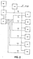
- La figure 2 représente schématiquement une organisation générale des circuits de contrôle du système de la figure 1.
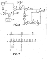
- La figure 3 représente schématiquement un circuit logique permettant de calculer l'estimation du trafic de données sur un interface conformément à l'invention.
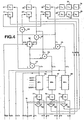
- Les figures 4 et 5 représentent schématiquement un circuit logique permettant de déterminer la configuration de vitesses optimale pour chaque interface.
- La figure 6 représente plus en détails la configuration du
circuit 56 représenté schématiquement à la figure 4. - La figure 7 représente schématiquement les impulsions de chronologie délivrées par les circuits Hl et H2 des figures 4 et 5.
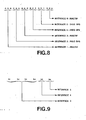
- La figure 8 montre un exemple de chaîne à 18 bits représentant une configuration particulière de vitesses attribuée selon l'invention.
- La figure 9 montre schématiquement la répartition des informations binaires transmises à chaque instant de signalisation dans l'exemple de configuration de vitesses de la figure 8.
- FIG. 1 schematically represents a transmission system to which the present invention can be applied.
- FIG. 2 schematically represents a general organization of the control circuits of the system of FIG. 1.
- FIG. 3 schematically represents a logic circuit making it possible to calculate the estimate of the data traffic on an interface in accordance with the invention.
- Figures 4 and 5 schematically represent a logic circuit for determining the optimal speed configuration for each interface.
- FIG. 6 shows in more detail the configuration of the
circuit 56 shown schematically in FIG. 4. - FIG. 7 schematically represents the chronology pulses delivered by the circuits Hl and H 2 of FIGS. 4 and 5.
- FIG. 8 shows an example of an 18-bit chain representing a particular configuration of speeds assigned according to the invention.
- FIG. 9 schematically shows the distribution of the binary information transmitted at each signaling instant in the example of speed configuration of FIG. 8.
La figure 1 représente très schématiquement une configuration générale de réseau de transmission auquel peut être appliquée la présente invention.FIG. 1 very schematically represents a general configuration of the transmission network to which the present invention can be applied.
Le réseau de la figure 1 comporte deux stations éloignées A et B reliées par un canal de transmission commun C. Les terminaux TA1, TA2, ... , --TA6 de la station A sont connectés au canal commun C par l'intermédiaire d'interfaces IAI, IA2, ..., IA6, d'un multiplexeur/démultiplexeur XA et d'un modem MA. De même les terminaux TB1, TB2, ..., TB6 de la station B --sont connectés au canal de-transmission commun C par l'intermédiaire d'interfaces IB1, IB2, ..., IB6, d'un multiplexeur/ démultiplexeur XB et d'un modem MB. Le terminal TB6 n'est pas directement relié au multiplexeur/démultiplexeur XB comme le sont les terminaux TB1 et TB2, il est relié par l'intermédiaire de deux modems MSl, MS2 et une ligne de transmission secondaire LS, l'ensemble constituant un réseau secondaire.The network of FIG. 1 comprises two remote stations A and B linked by a common transmission channel C. The terminals TA1, TA2, ..., --TA6 of station A are connected to the common channel C via d 'IAI, IA2, ..., IA6 interfaces, an XA multiplexer / demultiplexer and an MA modem. Likewise the terminals TB1, TB2, ..., TB6 of station B - are connected to the common transmission channel C via interfaces IB1, IB2, ..., IB6, a multiplexer / XB demultiplexer and an MB modem. The terminal TB6 is not directly connected to the multiplexer / demultiplexer XB as are the terminals TB1 and TB2, it is connected via two modems MSl, MS2 and a secondary transmission line LS, the whole constituting a network secondary.
Il est à noter que toutes les lignes de transmission représentées sont unidirectionnelles et que les vitesses de transmission peuvent très bien être différentes, pour un même interface dans les deux sens de transmission.It should be noted that all the transmission lines shown are unidirectional and that the transmission speeds may very well be different, for the same interface in both directions of transmission.
De plus, il va de soi qu'on a schématisé un système à six interfaces pour fixer les idées, mais le nombre d'interfaces maximal admissible peut être différent et variera notamment en fonction de la vitesse maximale du canal commun C et de la vitesse minimale des terminaux. Par exemple un système où le canal commun peut fonctionner à 14400 bits par seconde (BPS) où la vitesse des terminaux ne descend pas au-dessous de 2400 BPS et peut varier par incréments de 2400 BPS, acceptera, au maximum six interfaces.In addition, it goes without saying that a system with six interfaces has been schematized for fixing ideas, but the maximum number of interfaces admissible may be different and will vary in particular depending on the maximum speed of the common channel C and the speed minimum of terminals. For example a system where the common channel can operate at 14400 bits per second (BPS) where the speed of the terminals does not drop below 2400 BPS and can vary in increments of 2400 BPS, will accept, at most six interfaces.
Sur la figure 2, on a très schématiquement montré un organisation générale des circuits de contrôle du système au niveau d'une station, A par exemple.In FIG. 2, a general diagram has been shown of a general organization of the system control circuits at the level of a station, A for example.
La station fonctionne sous la commande d'une logique de contrôle LC qui peut être par exemple un microprocesseur, une mémoire de données MD et un module de commande de chronologie CH.The station operates under the control of an LC control logic which can be for example a microprocessor, a data memory MD and a chronology control module CH.
La logique de contrôle LC est connectée aux divers interfaces IA1, IA2, ..., IA6 par un bus de contrôle BC, pour effectuer tous les tests et commandes nécessaires à la transmission des données. Elle contrôle également l'envoi et la réception des messages de supervision échangés par les deux stations par l'intermédiaire de l'unité d'entrée/sortie I/O qui est connectée au modem MA (non représenté, voir figure 1) par une ligne SV. Hormis les opérations particulières liées à la présente invention et qui seront décrites en détail plus loin, la logique LC effectue toutes les opérations de commandes et de supervision nécessitées par le fonctionnement d'un système de transmission du type représenté à la figure 1 et qui sont bien connues dans l'art antérieur.The LC control logic is connected to the various interfaces IA1, IA2, ..., IA6 by a control bus BC, to carry out all the tests and commands necessary for the transmission of the data. It also controls the sending and reception of supervision messages exchanged by the two stations via the I / O input / output unit which is connected to the MA modem (not shown, see Figure 1) by a line SV. Apart from the specific operations linked to the present invention and which will be described in detail below, the LC logic performs all of the control and supervision operations required by the operation of a transmission system of the type represented in FIG. 1 and which are well known in the prior art.
La mémoire de données MD sert, d'une manière classique, à l'emmagasinage permanent ou temporaire de toutes les données nécessitant un traitement par la logique LC du système.The data memory MD is used, in a conventional manner, for the permanent or temporary storage of all the data requiring processing by the LC logic of the system.
Enfin, le module de commande de chronologie CH distribue les impulsions de chronologie aux divers organes du système, notamment à la logique LC, par une ligne CL, et aux divers interfaces IA1, IA2, ..., IA6 par des lignes CI1, CI2, ..., CI6.Finally, the chronology control module CH distributes the chronology pulses to the various organs of the system, in particular to the logic LC, by a line CL, and to the various interfaces IA1, IA2, ..., IA6 by lines CI1, CI2 , ..., CI6.
Les diverses unités représentées à la figure 2 et qui viennent d'être très brièvement évoquées sont toutes bien connues dans la technique, et ne nécessitent donc pas de description plus détaillée.The various units represented in FIG. 2 and which have just been very briefly mentioned are all well known in the art, and therefore do not require a more detailed description.
Afin de fixer les idées et de permettre une meilleure compréhension de l'invention, on se fixera les hypothèses suivantes (qui correspondent toutes à des situations classiques ou à des conditions très facilement réalisables) :
- . les lignes actives ayant à l'une de leurs extrémités un modem connecté à un réseau secondaire sont considérées comme fonctionnant impérativement à la vitesse du réseau secondaire;
- . les terminaux connectés aux autres lignes peuvent fonctionner jusqu'à la vitesse maximale du canal commun de transmission (dans le cas contraire, on peut prévoir que ces terminaux indiquent systématiquement à travers leur interface la vitesse maximale acceptée);
- . les deux voies de transmission correspondant respectivement aux deux sens de transmission, sont totalement indépendantes mais le processus d'affectation et d'optimisation des vitesses est le même; cela signifie notamment que la vitesse de transmission sur une voie donnée ne sera pas nécessairement la même dans les deux sens;
- . les modems attachés au réseau secondaire sont capables de changer automatiquement de vitesse et c'est le modem secondaire connecté à l'interface du multiplexeur qui accepte la commande de vitesse du modem attaché au canal commun et contrôle automatiquement la vitesse des autres modems connectés au réseau secondaire (les modems IBM de la série 386X satisfont cette hypothèse).
- . active lines having at one of their ends a modem connected to a secondary network are considered to operate imperatively at the speed of the secondary network;
- . the terminals connected to the other lines can operate up to the maximum speed of the common transmission channel (otherwise, it can be provided that these terminals systematically indicate through their interface the maximum speed accepted);
- . the two transmission channels corresponding respectively to the two directions of transmission, are completely independent but the process of allocation and optimization of speeds is the same; this means in particular that the transmission speed on a given channel will not necessarily be the same in both directions;
- . the modems attached to the secondary network are capable of automatically changing speed and it is the secondary modem connected to the interface of the multiplexer which accepts the speed command from the modem attached to the common channel and automatically controls the speed of the other modems connected to the network secondary (IBM 386X series modems satisfy this assumption).
Conformément à l'invention, pour une situation donnée dans laquelle plusieurs lignes sont actives aux deux extrémités du canal de transmission commun, on attribue la plus grande vitesse de transmission à la ligne (unidirectionnelle) ayant en moyenne le traffic de données à transmettre le plus important.According to the invention, for a given situation in which several lines are active at the two ends of the common transmission channel, the highest transmission speed is assigned to the line (unidirectional) having the average data traffic to be transmitted the most important.
Par exemple si le canal commun C fonctionne à 9600 bits par seconde (BPS), que la ligne secondaire LS avec les modems MS1 et MS2 fonctionne en permanence à 2400 BPS, que l'éventail de vitesses du système varie de 2400 à 9600 BPS par incréments de 2400 BPS et qu'il y a deux interfaces actifs à vitesse libre IA1 et IA2, il restera dans chaque sens de transmission deux vitesses disponibles : 4800 et 2400 BPS.For example if common channel C operates at 9600 bits per second (BPS), the secondary line LS with modems MS1 and MS2 operates continuously at 2400 BPS, that the range of system speeds varies from 2400 to 9600 BPS per increments of 2400 BPS and there are two active interfaces at free speed IA1 and IA2, there will remain in each direction of transmission two speeds available: 4800 and 2400 BPS.
Si la configuration est telle que le trafic de données à transmettre de A vers B est plus important sur IA1 que sur IB1 d'une part et que le trafic de données à transférer de B vers A est plus important sur IB2 que sur IA2, l'affectation des vitesses pourra se faire comme suit :

Comme le trafic de données à transmettre dans les différentes lignes peut varier au cours du temps, la présente invention prévoit de réaliser l'affectation des vitesses d'une manière automatique et dynamique. Pour ce faire chaque émetteur comporte des moyens pour tester les différents interfaces à vitesses "libres" (par opposition aux interfaces où les vitesses sont imposées, par exemple ceux connectés à des réseaux secondaires) qui lui sont connectés, pour calculer des grandeurs représentatives des trafics sur ces interfaces, et déterminer une hiérarchie de ces grandeurs. Ensuite, chaque émetteur affectera les vitesses de transmission des terminaux qui lui sont connectées en fonction de ces grandeurs et de cette hiérarchie, communiquera cette configuration de vitesses au récepteur à l'autre extrémité du canal multiplex commun C, et enfin réalisera la transmission des données selon cette configuration.As the data traffic to be transmitted in the different lines can vary over time, the present invention provides for the assignment of speeds in an automatic and dynamic manner. To do this, each transmitter includes means for testing the different interfaces with "free" speeds (as opposed to the interfaces where the speeds are imposed, for example those connected to secondary networks) which are connected to it, to calculate quantities representative of the traffics. on these interfaces, and determine a hierarchy of these quantities. Then, each transmitter will assign the transmission speeds of the terminals connected to it according to these quantities and this hierarchy, will communicate this speed configuration to the receiver at the other end of the common multiplex channel C, and finally will carry out the data transmission. according to this configuration.
Le calcul de ces grandeurs nécessite tout d'abord la détection et la mesure d'éléments directement liés à la présence d'informations significatives sur les lignes considérées, comme par exemple les bits "1", ou les bits "0", ou les transitions. Dans tous les exemples qui vont suivre, on a choisi de compter les bits "0", car avec les standards actuels du CCITT, une ligne à l'état de repos doit transmettre continuellement des bits "1", et on conçoit donc aisément que dans ce contexte particulier le comptage des bits "1" ne serait pas représentatif de l'activité de la ligne.The calculation of these quantities requires first of all the detection and measurement of elements directly linked to the presence of significant information on the lines considered, such as for example the bits "1", or the bits "0", or the transitions. In all the examples which follow, we have chosen to count the bits "0", because with the current CCITT standards, a line in the idle state must continuously transmit bits "1", and it is therefore easy to imagine that in this particular context the counting of bits "1" would not be representative of the activity of the line.
L'approche la plus simple pour déterminer les grandeurs représentatives des trafics consisterait à utiliser directement le nombre de bits "0" traversant un interface donné par -unité de temps. Chacune de ces grandeurs se présenterait alors sous la forme :
L'utilisation de cette formule simple a cependant l'inconvénient de générer des configurations très stables et des phénomènes d'hystérésis importants. En effet, une ligne fonctionnant deux fois moins vite qu'une autre fournira deux fois moins de bits par unité de temps. Cependant toute ligne présente habituellement une activité minimale par exemple du type POLL/NACK (protocole conventionnel Question/Réponse) qui, s'il se déroule à grande vitesse risque de faire apparaître une activité importante par rapport à une autre ligne à basse vitesse mais à trafic important.The use of this simple formula, however, has the disadvantage of generating very stable configurations and significant hysteresis phenomena. Indeed, a line running twice as fast as another will provide half the bits per unit of time. However, any line usually has minimal activity, for example of the POLL / NACK type (conventional Question / Answer protocol) which, if it takes place at high speed, may cause significant activity to appear compared to another line at low speed but at heavy traffic.
Une meilleure approche pourrait consister à pondérer la quantité de bits "0" par la vitesse de transmission ce qui revient en quelque sorte à mesurer la durée de l'activité de transmission de données. On pourrait alors utiliser une grandeur du type suivant :
L'utilisation de cette formule a cette fois l'inconvénient de générer dans certains cas des situations instables : par exemple lorsque deux lignes ont sensiblement le même trafic, cette formule peut conduire à une situation où ces deux lignes échangent constamment leurs vitesses.The use of this formula has this disadvantage of generating in certain cases unstable situations: for example when two lines have substantially the same traffic, this formula can lead to a situation where these two lines constantly exchange their speeds.
Conformément à l'invention, on a trouvé que la solution la plus appropriée consistait à faire une combinaison linéaire des deux approches ci-dessus. Plus particulièrement on a trouvé qu'il était souhaitable d'utiliser une grandeur du type ci-après :
L'analyse des valeurs obtenues pour la fonction ![]()
![]()
![]()

- où

- β est un coefficient compris entre zéro et un, définissant l'effet de mémorisation des mesures précédentes (le système étant d'autant plus stable que sera petit).
- or
- β is a coefficient between zero and one, defining the memorizing effect of the previous measurements (the system being more stable the smaller will be).
On a représenté sur la figure 3 un circuit logique montrant comment on peut calculer les différentes valeurs de ![]()
![]()
Les coefficients a et p sont chargés une fois pour toutes dans les registres respectifs 10 et 11. Le registre 12 est chargé par le rapport VM/Vi, les valeurs VM et Vi étant prélevées dans la mémoire de données MD (qui est mise à jour au fur et à mesure de l'attribution des vitesses), et le rapport étant effectué par la logique de commande LC. Enfin, le registre 13 contient le nombre de bits ![]()
![]()
Le sommateur 14, qui reçoit -a et 1 sur ses entrées respectives transmet le résultat (1-a) à une entrée du multiplicateur 15 dont la seconde entrée reçoit VM/Vi. Les entrées du sommateur 16 reçoivent respectivement les signaux de sortie du registre 10, c'est-à-dire a, et du multiplicateur 15, c'est-à-dire (1-α)VM/Vi. La sortie du sommateur 16 transmet le résultat α+(1-α)VM/Vi à une entrée du multiplicateur 17, dont la seconde entrée reçoit ![]()
![]()
![]()
![]()
![]()
![]()
Le signal de sortie du sommateur 19 est appliqué par l'intermédiaire d'un circuit à retard 22 à la seconde entrée du multiplicateur 21. Le circuit à retard 22 introduit un retard θ=tn-tn-1. Ainsi, on voit que la ligne de sortie 23 du sommateur 19 produit le signal ![]()
![]()
![]()
![]()
![]()
![]()
Une fois les différents ![]()
![]()
Ensuite, on effectue l'attribution des vitesses à partir d'une comparaison entre les différents trafics mesurés et les différentes vitesses possibles. En gardant le même exemple que ci-dessus (c'est-à-dire une somme des vitesses libres de 12 000 BPS et trois interfaces actifs à vitesses libres) on va donner ci-après un exemple de procédure d'attribution de vitesses.Next, the speeds are allocated from a comparison between the different traffics measured and the different possible speeds. Keeping the same example as above (that is to say a sum of the free speeds of 12,000 BPS and three active interfaces with free speeds) an example of the speed allocation procedure will be given below.
On calcule tout d'abord :
- où Σ3 1 Vi est la somme S des vitesses libres (dans le présent exemple S=12000), et
- Σ3 1 Tn i est la somme des estimations de trafic effectuées selon la formule donnée plus haut, pour chaque interface au temps tn.
- where Σ 3 1 V i is the sum S of the free speeds (in this example S = 12000), and
- Σ 3 1 Tn i is the sum of the traffic estimates made according to the formula given above, for each interface at time t n .
Il s'agit alors d'ajuster au mieux la série des ![]()
![]()
Pour chacune des trois valeurs de kTi, on cherche pi tel que ! KTi - 2400 pi ! est minimum. θn trouve ainsi trois valeurs de pi, soient p1, p2 et p3 (donnant trois valeurs de vitesses vi = 2400 pi, soient 2400 p1, 2400 p2, 2400 p3).For each of the three values of kT i , we search for p i such that! KT i - 2400 p i ! is minimum. We thus find three values of p i , let p 1 , p 2 and p 3 (giving three values of velocities v i = 2400 p i , let 2400 p 1 , 2400 p 2 , 2400 p 3 ).
On fait la somme S = 2400 (p1 + p2 +p3) = v1 + v2 + v3 We add S = 24 00 (p 1 + p 2 + p 3 ) = v 1 + v 2 + v 3
On compare s à S. La quatrième étape diffère selon que s=S (étape 4a), s>S (étape 4b) ou s<S (étape 4c).We compare s to S. The fourth step differs according to whether s = S (step 4a), s> S (step 4b) or s <S (step 4c).
Dans ce cas la procédure est terminée, et les vitesses à attribuer aux interfaces considérés sont respectivement V1 = v1, V2 = v2 et V3 = v3.In this case the procedure is completed, and the speeds to be assigned to the interfaces considered are V 1 = v 1 , V 2 = v 2 and V 3 = v 3 respectively .
Dans ce cas, on cherche l'interface i pour lequel (2400 pi - kTi) est maximal, et on prend comme nouvelle valeur de pi pour cet interface la valeur p'i=(pi-1), c'est-à-dire comme nouvelle valeur de vitesse la valeur 2400(pi-1), soit v'i=(vi-2400). Puis, on retourne à l'étape 2, et ainsi de suite juqu'à ce que s=S.In this case, we look for the interface i for which (2400 p i - kT i ) is maximum, and we take as new value of p i for this interface the value p ' i = (p i -1), i.e. as the new speed value the value 2400 (p i -1), i.e. v'i = (vi- 2400 ) . Then, we return to step 2, and so on until s = S.
Dans ce cas on cherche l'interface i pour lequel (kTi-2400 pi) est maximum, et on prend comme nouvelle valeur de pi pour cet interface la valeur p"i=(pi+1), c'est-à-dire comme nouvelle valeur de vitesse 2400(pi+1) soit v"i=(vi+2400). Puis, on retourne à l'étape 2 et ainsi de suite jusqu'à que s=S.In this case we look for the interface i for which (kT i -2400 p i ) is maximum, and we take as new value of p i for this interface the value p "i = (p i +1), that is ie as a new speed value 2400 (p i +1) let v " i = (v i +2400). Then, we return to step 2 and so on until s = S.
On a représenté schématiquement aux figures 4 et 5 un exemple de circuits logiques permettant de mettre en oeuvre le processus d'attribution de vitesses qui vient d'être décrit.FIGS. 4 and 5 show schematically an example of logic circuits making it possible to implement the speed allocation process which has just been described.
Ces circuits comprennent six registres 31, 32, ..., 36 pour stocker respectivement (et éventuellement) les valeurs Tn 1, Tn 2, ..., Tn 6 des trafics estimés au temps t sur les six interfaces conformément à la formule de l'invention, et six registres 41, 42, ..., 46 pour stocker les vitesses V1, V2, ..., V6 attribuées respectivement (et éventuellement) aux six interfaces au même temps t . Dans le présent exemple, on supposera pour ne pas compliquer inutilement le schéma et l'explication de son fonctionnement, qu'il n'existe que trois interfaces actifs à vitesses libres et que les données concernant ces trois interfaces sont stockées dans les registres 31, 32, 33 et 41, 42, 43. On n'a donc pas représenté, toujours pour simplifier, les circuits connectés aux registres restants, car ils sont tout à fait identiques à ceux qu'on a représenté pour les premiers registres.These circuits include six
On suppose donc qu'à un instant donné les registres 31, 32 et 33 contiennent respectivement les valeurs des trafics estimés T1, T2 et T3 des interfaces IA1, IA2 et IA3, et que les registres 41, 42 et 43 contiennent respectivement les vitesses V1, V2 et V3 de ces mêmes interfaces.It is therefore assumed that at a given time the
Le sommateur 50 permet de faire la somme ΣVi = V1 +V2 +V3 qu'on appellera S pour simplifier et le sommateur 51 de faire la somme ΣTi = T1+T2+T3. Ces sommes sont appliquées à un circuit diviseur 52 qui calcule k = ΣVi/ΣTi=S/ΣTi.The
Les multiplicateurs 53, 54 et 55 effectuent respectivement les produits kT1, kT2 et kT3, qui sont respectivement appliqués à l'une des entrées de trois circuits de calcul de minimum 56, 57 et 58.The
La fonction et la structure de chacun de ces circuits (qui sont tout à fait identiques) vont être expliquées en se référant à la figure 6 qui montre un exemple plus détaillé de l'un de ces circuits, 56 par exemple.The function and structure of each of these circuits (which are completely identical) will be explained with reference to FIG. 6 which shows a more detailed example of one of these circuits, 56 for example.
Le rôle du circuit 56 est, tout d'abord de calculer les entités kTi-2400 pi, pour toutes les valeurs de pi, puis de trouver la valeur de pi, donc de vi, pour laquelle cette entité est minimale, conformément à l'étape 1 du processus décrit plus haut.The role of
Le circuit comprend cinq registres 59, 60, 61, 62, 63 contenant respectivement les cinq vitesses libres 2400, 4800, 7200, 9600 et 12 000. Les sorties de ces registres sont respectivement connectées aux premières entrées de cinq sommateurs 64, 65, 66, 67, 68, dont les secondes entrées reçoivent le produit -kT1 obtenu en inversant le signal d'entrée du circuit 56 dans un inverseur de signe 69. Les résultats Δ1, Δ2' Δ3, Δ4 et Δ5 des cinq opérations |kTi-2400pi| sont envoyés dans un circuit de comparaison/ décision 70 qui détermine laquelle des valeurs Δ1, Δ2, Δ3, Δ4 et Δ5 est la plus faible. Ce circuit comporte cinq sorties et il envoie un signal de conditionnement sur celle de ses sorties qui correspond à la valeur de A la plus faible. Ces cinq sorties sont respectivement connectées aux premières entrées de cinq portes ET 71, 72, 73, 74 et 75 dont les secondes entrées sont respectivement connectées aux sorties des registres 59 à 63 et reçoivent donc les cinq vitesses 2400 à 12 000. Les sorties des portes 71 à 75 constituent les entrées d'une porte OU 76, dont la sortie va transmettre celle des cinq vitesses 2400 à 12 000 qui correspond à la valeur de Δ la plus faible, soit v1.The circuit includes five
Il en est de même pour les circuits 57 et 58 qui vont délivrer respectivement à leurs sorties les valeurs v2 et v3 correspondant aux valeurs de A minimales calculées dans chacun d'eux.It is the same for
Les valeurs v1, v2 et v3 sont respectivement introduites dans trois registres 77, 78 et 79.The values v 1 , v 2 and v 3 are respectively introduced into three
Les sorties de ces trois registres sont connectées à un sommateur 80 (figure 5) dont la sortie délivre la somme s=vl+v2+v3. Cette sortie est connectée à une première entrée d'un circuit sommateur 81, dont la seconde entrée reçoit le signal -S=-(V1+V2+V3) en provenance du sommateur 50, après inversion de signe en 82. Le circuit 81 fait donc l'opération s-S et produit un signal de conditionnement sur l'une de ses trois sorties selon que s-S=0, s-S>0, ou s-S<0 (étape 3 du processus).The outputs of these three registers are connected to an adder 80 (Figure 5) whose output delivers the sum s = v l + v 2 + v 3 . This output is connected to a first input of a summing
La première ligne de sortie 83 du circuit 81 (celle qui est activée pour s-S=0) est connectée à chacune des premières entrées de trois portes ET 84, 85 et 86. Les secondes entrées de ces portes ET sont respectivement connectées aux trois sorties des registres 77, 78 et 79. Quand aux sorties des portes ET 84, 85 et 86, elles sont respectivement connectées aux entrées des registres 41, 42 et 43.The
On voit ainsi que, lorsque s-S=0, les contenus des registres 77, 78 et 79 sont transférés dans les registres 41, 42 et 43 qui définissent les vitesses des trois interfaces IA1, IA2 et IA3, conformément à l'étape 4a du processus.It can thus be seen that, when sS = 0, the contents of
Si le circuit 81 détermine que s-S est supérieur à zéro, c'est la deuxième ligne de sortie 87 du circuit 81 qui est activée. Cette ligne applique un signal de conditionnement à un circuit 88 dont la fonction est de déterminer quel est celui des trois interfaces pour lequel l'entité (2400pi-kTi) ou (vi-kTi) est maximale (étape 4b du processus).If
Le circuit 88 comporte trois entrées recevant respectivement les valeurs v1-kT1, v2-kT2 et v3-kT3. Ces valeurs sont fournies respectivement par les sorties de trois sommateurs 89, 90 et 91. Les premières entrées de ces trois sommateurs sont respectivement reliées aux lignes de sorties des registres 77, 78 et 79 (qui délivrent les valeurs vi, v2 et v3). Les secondes entrées de ces sommateurs sont respectivement reliées, par l'intermédiaire de trois inverseurs de signe 92, 93 et 94 aux lignes de sortie des sommateurs 53, 54 et 55 (qui délivrent les produits kT1, kT2 et kT3).
Le circuit 88, qui comporte trois sorties compare les trois valeurs v1-kTi qui lui sont soumises, détermine celle qui est maximale, et délivre un signal de conditionnement sur celle de ses sorties qui correspond à l'interface dont la valeur vi-kTi est maximale. On supposera pour fixer les idées qu'il s'agit de la sortie 1.The
Les sorties du circuit 88 sont respectivement connectées aux premières entrées de trois portes ET 95, 96 et 97 dont chacune des secondes entrées reçoit la valeur 2400 d'un registre à contenu fixe 98. Les sorties de ces portes ET sont respectivement connectées aux premières entrées de trois sommateurs 99, 100 et 101 par l'intermédiaire de trois inverseurs de signe 116, 117 et 118. Ainsi, la valeur -2400 est appliquée à seulement l'un (99) de ces sommateurs, puisque l'une seulement (95) des portes ET 95, 96 et 97 est passante. Les secondes entrées des sommateurs 99, 100 et 101 reçoivent respectivement les valeurs vl, v2 et v3 délivrées par les registres 77, 78 et 79. Le sommateur 99 va délivrer sur sa sortie la valeur vl-2400, qui est alors transférée dans le registre 77 où elle va remplacer la valeur précédente c'est-à-dire v1. Les contenus des deux autres registres ne changent pas puisque les deux autres sommateurs 101 et 102 ayant une entrée inactive (les sorties des portes ET 96 et 97) ne donnent pas de signal de sortie.The outputs of
Les registres 77, 78 et 79 contiennent alors une nouvelle série de vitesses vl-2400, v2 et v3 dont la somme s'=s-2400 est à nouveau effectuée par le sommateur 80. Puis le circuit 81 détermine à nouveau si s' est égal, supérieur ou inférieur à S et ainsi de suite jusqu'à ce qu'on arrive à l'égalité des deux sommes, auquel cas les valeurs des vitesses contenues dans les registres 77, 78 et 79 sont transférées dans les registres 41, 42 et 43, comme on l'a vu plus haut dans l'étape 4a, et constituent les vitesses attribuées respectivement aux interfaces IA1, IA2 et IA3.The
Si après la comparaison effectuée par le circuit 81 à l'étape 3 du processus, le circuit détermine que s-S est inférieur à zéro, c'est alors la troisième ligne de sortie 102 du circuit 81 qui est activée. Cette ligne délivre alors un signal de conditionnement à un circuit 103 dont la fonction est de déterminer quel est celui des trois interfaces pour lequel l'entité (kTi-2400pi) ou (kTi-vi) est maximale (étape 4c du processus).If after the comparison made by the
Le circuit 103 comporte trois entrées recevant respectivement les valeurs kT1-v1, kT2-v2 et kT3-v3. Ces valeurs sont fournies respectivement par les sorties de trois sommateurs 104, 105 et 106. Les premières entrées de ces trois sommateurs sont respectivement reliées par l'intermédiaire de trois inverseurs de signe 107, 108 et 109, aux lignes de sorties des registres 77, 78 et 79 (qui délivrent les valeurs vi, v2 et v3). Les secondes entrées de ces sommateurs sont respectivement reliées aux lignes de sortie des sommateurs 53, 54 et 55 (qui délivrent les produits kT1, kT2 et kT3).The circuit 103 has three inputs receiving respectively the values kT 1 -v 1 , kT 2 -v 2 and kT3-v3. These values are supplied respectively by the outputs of three
Le circuit 103, qui comporte trois sorties, compare les trois valeurs kTi-vi qui lui sont soumises, détermine celle qui est maximale, et délivre un signal de conditionnement sur celle de ses sorties qui correspond à l'interface dont la valeur kTi-vi est maximale. On supposera pour fixer les idées qu'il s'agit de la sortie 2.The circuit 103, which has three outputs, compares the three values kT i -v i which are subject to it, determines which one is maximum, and delivers a conditioning signal on that of its outputs which corresponds to the interface whose value kT i -v i is maximum. We will assume to fix the ideas that it is
Les sorties du circuit 103 sont respectivement connectées aux premières entrées de trois portes ET 110, 111 et 112 dont chacune des secondes entrées reçoit la valeur 2400 du registre à contenu fixe 98. Les sorties de ces portes ET sont connectées aux premières entrées de trois sommateurs 113, 114 et 115. Ainsi, la valeur 2400 est appliquée à seulement l'un (114) de ces derniers sommateurs, puisque l'une seulement (111) des portes ET 110, 111, 112 est passante. Les secondes entrées des sommateurs 113, 114 et 115 reçoivent respectivement les valeurs v1, v2 et v3 délivrées par les registres 77, 78 et 79. Le sommateur 114 va délivrer sur sa sortie la valeur v2+2400, qui est alors transférée dans le registre 78 où elle va remplacer la valeur précédente c'est-à-dire v2. Les contenus des deux autres registres ne changent pas puisque les deux autres sommateurs 113 et 115 ayant une entrée inactive (les sorties des portes ET 110 et 112) ne donnent pas de signal de sortie.The outputs of circuit 103 are respectively connected to the first inputs of three AND
Les registres 77, 78 et 79 contiennent alors une nouvelle série de vitesses v1, v2+2400, et v3 dont la somme s"=s+2400 est à nouveau effectuée par le sommateur 80. Puis le circuit 81 détermine à nouveau si s" est égal, supérieur ou inférieur à S et ainsi de suite jusqu'à ce qu'on arrive à l'égalité des deux sommes, auquel cas les valeurs des vitesses contenues dans les registres 77, 78 et 79 sont transférées dans les registres 41, 42 et 43, comme on l'a vu plus haut.The
Les circuits logiques représentés aux figures 4 et 5 comportent également des circuits de distribution de signaux chronologiques afin de commander le déroulement approprié des diverses étapes du processus. En fait, deux circuits de chronologie sont suffisants. Le premier, H1 (figure 4), est connecté à une troisième entrée des portes ET 84, 85 et 86. Il commande le transfert des valeurs de vitesses calculées par la logique et définitivement attribuées (pour la période de temps considérée) aux trois interfaces, dans les registres 41, 42 et 43. La période des impulsions délivrées par le circuit H1 est égale à la période d'échantillonnage, c'est-à-dire 6 (on rappelle que θ=tn-tn-1). Le second circuit de chronologie H2 (figure 5) est connecté à une troisième entrée des portes ET 95, 96, 97, 116, 117 et 118. Il commande le transfert des valeurs vi+2400 ou vi-2400 calculées durant les étapes 4b ou 4c du processus dans les registres 77, 78 ou 79. Du fait que les étapes 4b ou 4c peuvent être répétées plusieurs fois au cours d'un même processus, la période des impulsions délivrées par le circuit H2 sera un sous multiple de e, par exemple 4 (dans le présent exemple les étapes 4b ou 4c ne peuvent pas se répéter plus de quatre fois). La figure 7 montre schématiquement les impulsions délivrées respectivement par les circuits Hl et H2.The logic circuits represented in FIGS. 4 and 5 also include circuits for distributing chronological signals in order to control the appropriate progress of the various stages of the process. In fact, two chronological circuits are sufficient. The first, H 1 (Figure 4), is connected to a third input of AND
En pratique la procédure d'attribution dynamique des vitesses conformes à l'invention est utilisée dès le démarrage du système, mais il est bien entendu nécessaire à la mise en route, de prévoir une configuration de vitesses initiales prédéterminée. Cette configuration initiale dépendra notamment de :
- . la vitesse du canal multiplex commun,
- . l'éventail de vitesses disponibles,
- . l'existence de réseaux secondaires à vitesse fixe, et
- . le nombre d'interfaces de terminaux ou lignes reliés au système.
- . the speed of the common multiplex channel,
- . the range of speeds available,
- . the existence of secondary fixed-speed networks, and
- . the number of terminal or line interfaces connected to the system.
Le tableau suivant montre un exemple de configuration de vitesses initiales applicable à un système de transmission à 14 400 BPS et à six interfaces avec vitesse minimale à 2400 BPS et échelonnement des vitesses par multiples de 2400 BPS.

On a mentionné au début de la description de l'invention que, une fois que les vitesses de transmission ont été attribuées aux divers interfaces pour un sens donné de la transmission, par exemple de la station A vers la station B, il faut indiquer aux récepteurs de la station B quelles sont les vitesses qui ont été attribuées aux divers interfaces, de façon que ces récepteurs puissent se synchroniser convenablement. La transmission de cette information peut s'effectuer sous la forme d'une chaîne de 18 bits (si l'on garde toujours l'exemple de réalisation décrit plus haut), dans laquelle chaque groupe de trois bits représente l'état et/ou la vitesse de transmission correspondant à chaque interface, en adoptant le code suivant par exemple :

La transmission de cette information, qui est très courte, s'effectue pour chaque interface durant une période d'inactivité de l'interface.The transmission of this information, which is very short, takes place for each interface during a period of inactivity of the interface.
La figure 8 montre un exemple d'une telle chaîne de bits lorsque seuls les interfaces 2, 4 et 5 sont actifs. Une telle chaîne permet de définir simplement l'affectation des six informations binaires qui seront transmises à chaque instant de signalisation sur le canal multiplex C tant que la configuration de vitesses restera la même que celle représentée à la figure 8. Ces six informations binaires bl à b6 sont schématisées à la figure 9, où l'on voit que les quatre premières informations binaires bl à b4 sont affectées à l'interface 2 (dont la vitesse est 4x2400 BPS) et les informations binaires restantes b5 et b6 sont respectivement affectées aux interfaces 4 et 5, dont la vitesse est 2400 BPS.Figure 8 shows an example of such a bit string when only interfaces 2, 4 and 5 are active. Such a chain makes it possible to simply define the allocation of the six binary items of information which will be transmitted at each signaling instant on the multiplex channel C as long as the speed configuration remains the same as that shown in FIG. 8. These six binary items of bl to b6 are shown diagrammatically in FIG. 9, where it can be seen that the first four binary information b1 to b4 are assigned to the interface 2 (whose speed is 4x2400 BPS) and the remaining binary information b5 and b6 are respectively assigned to the
Claims (6)

dans laquelle :
in which :

Priority Applications (4)
| Application Number | Priority Date | Filing Date | Title |
|---|---|---|---|
| EP82430049A EP0112953B1 (en) | 1982-12-28 | 1982-12-28 | Method of dynamic assignment of speeds in a multiplex transmission system |
| DE8282430049T DE3276041D1 (en) | 1982-12-28 | 1982-12-28 | Method of dynamic assignment of speeds in a multiplex transmission system |
| JP58232893A JPS59125133A (en) | 1982-12-28 | 1983-12-12 | Method of assigning communication velocity |
| US06/560,637 US4550399A (en) | 1982-12-28 | 1983-12-12 | Odynamical operating rate allocation process in a multiplex communication system |
Applications Claiming Priority (1)
| Application Number | Priority Date | Filing Date | Title |
|---|---|---|---|
| EP82430049A EP0112953B1 (en) | 1982-12-28 | 1982-12-28 | Method of dynamic assignment of speeds in a multiplex transmission system |
Publications (2)
| Publication Number | Publication Date |
|---|---|
| EP0112953A1 true EP0112953A1 (en) | 1984-07-11 |
| EP0112953B1 EP0112953B1 (en) | 1987-04-08 |
Family
ID=8189996
Family Applications (1)
| Application Number | Title | Priority Date | Filing Date |
|---|---|---|---|
| EP82430049A Expired EP0112953B1 (en) | 1982-12-28 | 1982-12-28 | Method of dynamic assignment of speeds in a multiplex transmission system |
Country Status (4)
| Country | Link |
|---|---|
| US (1) | US4550399A (en) |
| EP (1) | EP0112953B1 (en) |
| JP (1) | JPS59125133A (en) |
| DE (1) | DE3276041D1 (en) |
Cited By (8)
| Publication number | Priority date | Publication date | Assignee | Title |
|---|---|---|---|---|
| EP0178548A1 (en) * | 1984-10-15 | 1986-04-23 | Siemens Aktiengesellschaft | Method and circuit for the transmission of at least two binary data streams over a multiplex transmission section |
| EP0251587A2 (en) * | 1986-06-19 | 1988-01-07 | General DataComm, Inc. | Variable control and data rates in highly efficient multiplexer |
| US4912702A (en) * | 1987-12-23 | 1990-03-27 | Alcatel N.V. | Conditional multiplexer |
| WO1990010984A1 (en) * | 1989-03-14 | 1990-09-20 | Alcatel N.V. | Communication switching system |
| US5023869A (en) * | 1989-03-27 | 1991-06-11 | Alberta Telecommunications Research Centre | Method and apparatus for maximizing the transmission capacity of a multi-channel bidirectional communications link |
| EP0432315A1 (en) * | 1989-12-14 | 1991-06-19 | Koninklijke Philips Electronics N.V. | System and method for controlling the access rates of packet switching network stations |
| AU623402B2 (en) * | 1989-03-14 | 1992-05-14 | Alcatel N.V. | Communication switching system |
| US5751701A (en) * | 1996-07-19 | 1998-05-12 | Globespan Technologies, Inc. | Rate adaptive digital subscriber line ("RADSL") modem |
Families Citing this family (13)
| Publication number | Priority date | Publication date | Assignee | Title |
|---|---|---|---|---|
| JPH0632522B2 (en) * | 1983-12-29 | 1994-04-27 | 富士通株式会社 | Digital signal transmission method |
| US4884267A (en) * | 1986-12-27 | 1989-11-28 | Kabushiki Kaisha Kenwood | TDM transmission system |
| JP2692104B2 (en) * | 1988-02-12 | 1997-12-17 | 株式会社日立製作所 | Voice multiplexing system |
| US4891805A (en) * | 1988-06-13 | 1990-01-02 | Racal Data Communications Inc. | Multiplexer with dynamic bandwidth allocation |
| FR2643532B1 (en) * | 1989-02-17 | 1991-05-10 | France Etat | METHOD FOR RESERVING RATES AND TIME SWITCHES OF ASYNCHRONOUS PACKETS |
| AU627953B2 (en) * | 1989-11-15 | 1992-09-03 | Digital Equipment Corporation | Integrated communications link having dynamically allocatable bandwidth and a protocol for transmission or allocation information over the link |
| US5115309A (en) * | 1990-09-10 | 1992-05-19 | At&T Bell Laboratories | Method and apparatus for dynamic channel bandwidth allocation among multiple parallel video coders |
| US5392284A (en) * | 1990-09-20 | 1995-02-21 | Canon Kabushiki Kaisha | Multi-media communication device |
| JPH0514546A (en) * | 1991-07-05 | 1993-01-22 | Fujitsu Ltd | Wave band management system in communication |
| US5321721A (en) * | 1991-09-13 | 1994-06-14 | Sony Corporation | Spread spectrum communication system and transmitter-receiver |
| JPH0646082A (en) * | 1992-07-22 | 1994-02-18 | Toshiba Corp | Information transfer control system |
| IT1270938B (en) * | 1993-05-14 | 1997-05-16 | Cselt Centro Studi Lab Telecom | PROCEDURE FOR THE CONTROL OF THE TRANSMISSION ON A SAME CHANNEL OF INFORMATION FLOWS AT VARIABLE SPEED IN COMMUNICATION SYSTEMS BETWEEN MOBILE VEHICLES, AND A SYSTEM USING SUCH PROCEDURE |
| US6032193A (en) * | 1997-03-20 | 2000-02-29 | Niobrara Research And Development Corporation | Computer system having virtual circuit address altered by local computer to switch to different physical data link to increase data transmission bandwidth |
Citations (2)
| Publication number | Priority date | Publication date | Assignee | Title |
|---|---|---|---|---|
| US4270202A (en) * | 1977-05-11 | 1981-05-26 | Racal-Milgo, Inc. | Modem with automatic port reconfiguration apparatus |
| EP0064120A1 (en) * | 1981-04-30 | 1982-11-10 | International Business Machines Corporation | Process to determine the configuration of the active channels in a multiflex communication system, and device therefor |
Family Cites Families (6)
| Publication number | Priority date | Publication date | Assignee | Title |
|---|---|---|---|---|
| US3711650A (en) * | 1970-10-26 | 1973-01-16 | Logicon Inc | Adaptive pulse code modulation system |
| US3794768A (en) * | 1972-05-25 | 1974-02-26 | Bell Telephone Labor Inc | Cross-office connecting scheme for interconnecting multiplexers and central office terminals |
| JPS5539410A (en) * | 1978-09-13 | 1980-03-19 | Digital Computer Kk | Increasing method of transmission efficiency for data communication |
| JPS5620352A (en) * | 1979-07-28 | 1981-02-25 | Nippon Telegr & Teleph Corp <Ntt> | Communicating method by variable allocation time-division multiple access |
| US4320520A (en) * | 1980-06-27 | 1982-03-16 | Rolm Corporation | Transmitter/receiver for use on common cable communications system such as ethernet |
| US4471480A (en) * | 1981-12-23 | 1984-09-11 | International Telephone And Telegraph Corporation | Programmable controller for a TDM digital multiplexer-demultiplexer combination |
-
1982
- 1982-12-28 EP EP82430049A patent/EP0112953B1/en not_active Expired
- 1982-12-28 DE DE8282430049T patent/DE3276041D1/en not_active Expired
-
1983
- 1983-12-12 JP JP58232893A patent/JPS59125133A/en active Granted
- 1983-12-12 US US06/560,637 patent/US4550399A/en not_active Expired - Lifetime
Patent Citations (2)
| Publication number | Priority date | Publication date | Assignee | Title |
|---|---|---|---|---|
| US4270202A (en) * | 1977-05-11 | 1981-05-26 | Racal-Milgo, Inc. | Modem with automatic port reconfiguration apparatus |
| EP0064120A1 (en) * | 1981-04-30 | 1982-11-10 | International Business Machines Corporation | Process to determine the configuration of the active channels in a multiflex communication system, and device therefor |
Non-Patent Citations (1)
| Title |
|---|
| INTERNATIONAL CONFERENCE ON COMMUNICATIONS, 14-16 juin 1971, Montreal, pages 39-27 - 39-32, IEEE, New York, USA * |
Cited By (10)
| Publication number | Priority date | Publication date | Assignee | Title |
|---|---|---|---|---|
| EP0178548A1 (en) * | 1984-10-15 | 1986-04-23 | Siemens Aktiengesellschaft | Method and circuit for the transmission of at least two binary data streams over a multiplex transmission section |
| EP0251587A2 (en) * | 1986-06-19 | 1988-01-07 | General DataComm, Inc. | Variable control and data rates in highly efficient multiplexer |
| EP0251587A3 (en) * | 1986-06-19 | 1989-10-18 | General Datacomm, Inc. | Variable control and data rates in highly efficient multiplexer |
| US4912702A (en) * | 1987-12-23 | 1990-03-27 | Alcatel N.V. | Conditional multiplexer |
| WO1990010984A1 (en) * | 1989-03-14 | 1990-09-20 | Alcatel N.V. | Communication switching system |
| AU623402B2 (en) * | 1989-03-14 | 1992-05-14 | Alcatel N.V. | Communication switching system |
| US5023869A (en) * | 1989-03-27 | 1991-06-11 | Alberta Telecommunications Research Centre | Method and apparatus for maximizing the transmission capacity of a multi-channel bidirectional communications link |
| EP0432315A1 (en) * | 1989-12-14 | 1991-06-19 | Koninklijke Philips Electronics N.V. | System and method for controlling the access rates of packet switching network stations |
| US5751701A (en) * | 1996-07-19 | 1998-05-12 | Globespan Technologies, Inc. | Rate adaptive digital subscriber line ("RADSL") modem |
| US6167034A (en) * | 1996-07-19 | 2000-12-26 | Globespan Technologies, Inc. | Rate adaptive digital subscriber line (RADSL) modem |
Also Published As
| Publication number | Publication date |
|---|---|
| JPH0312813B2 (en) | 1991-02-21 |
| EP0112953B1 (en) | 1987-04-08 |
| US4550399A (en) | 1985-10-29 |
| JPS59125133A (en) | 1984-07-19 |
| DE3276041D1 (en) | 1987-05-14 |
Similar Documents
| Publication | Publication Date | Title |
|---|---|---|
| EP0112953B1 (en) | Method of dynamic assignment of speeds in a multiplex transmission system | |
| EP1261151B1 (en) | Resources allocation method in a MF-TDMA telecommunication system | |
| EP1155531B1 (en) | System and method for measuring the transfer durations and loss rates in high volume telecommunication networks | |
| EP0084389B1 (en) | Data transmission arrangement and communication network with preventive provision for error elimination | |
| FR2694828A1 (en) | Packet transfer computer bus. | |
| EP0616477A1 (en) | Least cost routing arrangement in a telecommunication network | |
| EP2725721B1 (en) | Method for dynamic allocation of shared resources in a time-frequency plane and related device | |
| WO2010010266A1 (en) | Technique for communicating between a plurality of nodes | |
| EP0505281B1 (en) | Synchronisation of terminal stations in a multirate half duplex tree network | |
| FR2779301A1 (en) | METHOD FOR IDENTIFYING DEVICES IN A COMMUNICATION NETWORK AND APPARATUS FOR IMPLEMENTING THE SAME | |
| CA1209712A (en) | Method and installation for sending digital data | |
| EP0609114A1 (en) | Method and device for bit rate management in an ATM network | |
| CA2158895C (en) | Point-to-multipoint time division multiple access transmission network | |
| CA1257006A (en) | Method and device for transmitting messages between stations through a broadcast local network | |
| EP1791306B1 (en) | Packetswitch for a telecommunication node | |
| EP0228528B1 (en) | Apparatus for implementing a code with a small digital sum variation in a fast digital transmission, and coding method using such an apparatus | |
| EP0933895A1 (en) | Method for detecting one or more free channels in an optical time multiplexed signal, a device for implementation and an application of the device | |
| EP1770927A1 (en) | Packet switching system for telecom network node | |
| FR2505582A1 (en) | SYSTEM FOR PHASING DIGITAL TRAINS AND ITS APPLICATION TO THE SWITCHING OF THESE TRAINS | |
| EP2606655B1 (en) | Method for switching an optical data stream, computer program product, and corresponding storage means and node | |
| EP0689371A1 (en) | Communication system having a network and multiplexing unit | |
| WO2001091405A2 (en) | Method for mutual transfers of control parameters through a communication network | |
| EP2449792B1 (en) | Method of handling a resource reservation request with associated device and node equipment | |
| EP1841151A1 (en) | Message switching system | |
| EP0270471B1 (en) | Packet switching system |
Legal Events
| Date | Code | Title | Description |
|---|---|---|---|
| PUAI | Public reference made under article 153(3) epc to a published international application that has entered the european phase |
Free format text: ORIGINAL CODE: 0009012 |
|
| AK | Designated contracting states |
Designated state(s): DE FR GB |
|
| 17P | Request for examination filed |
Effective date: 19841029 |
|
| GRAA | (expected) grant |
Free format text: ORIGINAL CODE: 0009210 |
|
| AK | Designated contracting states |
Kind code of ref document: B1 Designated state(s): DE FR GB |
|
| REF | Corresponds to: |
Ref document number: 3276041 Country of ref document: DE Date of ref document: 19870514 |
|
| PLBE | No opposition filed within time limit |
Free format text: ORIGINAL CODE: 0009261 |
|
| STAA | Information on the status of an ep patent application or granted ep patent |
Free format text: STATUS: NO OPPOSITION FILED WITHIN TIME LIMIT |
|
| 26N | No opposition filed | ||
| PGFP | Annual fee paid to national office [announced via postgrant information from national office to epo] |
Ref country code: FR Payment date: 19951128 Year of fee payment: 14 |
|
| PG25 | Lapsed in a contracting state [announced via postgrant information from national office to epo] |
Ref country code: FR Effective date: 19970829 |
|
| REG | Reference to a national code |
Ref country code: FR Ref legal event code: ST |
|
| PGFP | Annual fee paid to national office [announced via postgrant information from national office to epo] |
Ref country code: GB Payment date: 20011210 Year of fee payment: 20 |
|
| PGFP | Annual fee paid to national office [announced via postgrant information from national office to epo] |
Ref country code: DE Payment date: 20011211 Year of fee payment: 20 |
|
| REG | Reference to a national code |
Ref country code: GB Ref legal event code: IF02 |
|
| PG25 | Lapsed in a contracting state [announced via postgrant information from national office to epo] |
Ref country code: GB Free format text: LAPSE BECAUSE OF EXPIRATION OF PROTECTION Effective date: 20021227 |
|
| REG | Reference to a national code |
Ref country code: GB Ref legal event code: PE20 Effective date: 20021227 |