EP0107191A2 - Method and apparatus for coordination among distributed subsystems - Google Patents
Method and apparatus for coordination among distributed subsystems Download PDFInfo
- Publication number
- EP0107191A2 EP0107191A2 EP83110539A EP83110539A EP0107191A2 EP 0107191 A2 EP0107191 A2 EP 0107191A2 EP 83110539 A EP83110539 A EP 83110539A EP 83110539 A EP83110539 A EP 83110539A EP 0107191 A2 EP0107191 A2 EP 0107191A2
- Authority
- EP
- European Patent Office
- Prior art keywords
- subsystems
- subsystem
- workpiece
- coordination
- processing
- Prior art date
- Legal status (The legal status is an assumption and is not a legal conclusion. Google has not performed a legal analysis and makes no representation as to the accuracy of the status listed.)
- Granted
Links
Images


Classifications
-
- G—PHYSICS
- G05—CONTROLLING; REGULATING
- G05B—CONTROL OR REGULATING SYSTEMS IN GENERAL; FUNCTIONAL ELEMENTS OF SUCH SYSTEMS; MONITORING OR TESTING ARRANGEMENTS FOR SUCH SYSTEMS OR ELEMENTS
- G05B19/00—Programme-control systems
- G05B19/02—Programme-control systems electric
- G05B19/418—Total factory control, i.e. centrally controlling a plurality of machines, e.g. direct or distributed numerical control [DNC], flexible manufacturing systems [FMS], integrated manufacturing systems [IMS], computer integrated manufacturing [CIM]
- G05B19/41835—Total factory control, i.e. centrally controlling a plurality of machines, e.g. direct or distributed numerical control [DNC], flexible manufacturing systems [FMS], integrated manufacturing systems [IMS], computer integrated manufacturing [CIM] characterised by programme execution
-
- Y—GENERAL TAGGING OF NEW TECHNOLOGICAL DEVELOPMENTS; GENERAL TAGGING OF CROSS-SECTIONAL TECHNOLOGIES SPANNING OVER SEVERAL SECTIONS OF THE IPC; TECHNICAL SUBJECTS COVERED BY FORMER USPC CROSS-REFERENCE ART COLLECTIONS [XRACs] AND DIGESTS
- Y02—TECHNOLOGIES OR APPLICATIONS FOR MITIGATION OR ADAPTATION AGAINST CLIMATE CHANGE
- Y02P—CLIMATE CHANGE MITIGATION TECHNOLOGIES IN THE PRODUCTION OR PROCESSING OF GOODS
- Y02P90/00—Enabling technologies with a potential contribution to greenhouse gas [GHG] emissions mitigation
- Y02P90/02—Total factory control, e.g. smart factories, flexible manufacturing systems [FMS] or integrated manufacturing systems [IMS]
Definitions
- This invention relates to a method and apparatus for use in a system including a plurality of distributed subsystems carrying out the same or different functions, the apparatus being connected to the individual subsystems so that the subsystems can execute a series of processing while keeping coordination among them.
- a central specific subsystem In a system including a plurality of distributed subsystems, those which should participate in the processing and the order of works to be processed by each individual subsystem have been determined by a central specific subsystem. Such a centralized system has been defective in that operational failure of the central subsystem leads necessarily to shutdown of the whole system.
- the prior art centralized system has also been defective in that a vast amount of information must be collected or stored in a single unit in order to readily grasp the status of each individual subsystem.
- the prior art centralized system has further been defective in that a modification of the central subsystem is required to deal with additional provision of a subsystem or subsystems and alteration of the function of the existing subsystem or subsystems, and, for that purpose, the operation of the whole system must be stopped.
- the present invention which attains the above object is featured by the fact that each individual subsystem judges its own status and functions and coordinates to determine works to be executed by itself. More concretely, according to the present invention, a work executable by each individual subsystem in a process and works executable in processes before and after or forward and backward of that process are extracted from among a series of works, and, in order that the work in the succeeding process can be immediately executed after execution of the work in the preceding process on the basis of the result of work extraction, the executable ones of the subsystems coordinate with each other to select the one which should participitate in the execution of the works, and the order of works to be executed is determined in each individual subsystem.
- Fig. 1 shows the structure of a preferred embodiment of the system according to the present invention.
- the system includes a plurality of subsystems 1 to n (not shown) such as machine tools and/or robots.
- a workpiece is conveyed by a carrier running along a guide line extending from a warehouse, which is also a subsystem, to each of these subsystems.
- the workpiece is received and processed by one of the subsystems, and the processed orkpiece is then loaded on the carrier again and conveyed to another subsystem to be further processed.
- the workpiece Upon completion of a series of scheduled processing, the workpiece is finally delivered from the system.
- coordinators 11 to ln are provided according to the present invention. As shown in Fig. 1, these coordinators 11 to In are interconnected through associated information transmission controllers 21 to 2n and an information transmission loop 30 for exchange of information therebetween. These coordinators 11 to ln are also connected to associated subsystem controllers 41 to 4n respectively.
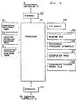
- Fig. 2 shows the internal structure of a preferred form of the coordinator 11.
- the coordinator 11 includes an interface 52 connected to the information transmission controller 21, an interface 53 connected to the subsystem controller 41, a processor 51, an input/output buffer 54, file memories 55 to 58, and three kinds of timers 59 to 61.
- Figs. 3a to 3g are flow charts of the steps of processing by the processor 51 shown in Fig. 2, and Figs. 4 to 7 illustrate the operation of the coordinator 11 shown in Fig. 2.
- the subsystems which are the machine tools and/or robots are designated by the.reference numerals 1 to 5, and the subsystem which is the warehouse is designated by the reference numeral 6 herein.
- the subsystem controllers 41 to 4n shown in Fig. 1 transmit data indicative of executable functions of the machine tools and/or robots of respective subsystems i connected thereto, to the coordinators 11 to ln respectively.
- the coordinator 11 stores the data transmitted from the controller 41 in the input/output buffer 54 (block 71 in Fig. 3a).
- the data is then stored in the executable function register file 55 provided to the coordinator 11 shown in Fig. 2 (block 72 in Fig. 3a).
- the subsystems 1 and 2 are the same machine tools and their executable functions are F 1 and F 4 as shown in Fig. 4.
- executable functions of the subsystem 3 are F 2 and F 7
- those of the subsystem 4 are F 3 and F 9
- those of the subsystem 5 are F 5 , F 6 and F 8 as shown in Fig. 4.
- the process flow shown in Fig. 5 indicates the procedure for working.
- the function F 2 or F 3 can be executed, and, after execution of the function F 2 or F 3 , the function F 4 can be executed on the workpiece P 1 .
- the functions F 6 , F 7 and F 8 can be executed on the workpiece P 2 in a relation entirely independent of execution of the functions F l , F2, F 3 , F 4 and F 5 on the workpiece P 1 .
- the function F 9 is executed on both of the workpieces P 1 and P 2 to complete all the works on the workpieces P 1 and P 2 .
- the process flow data for processing the workpieces P 1 and P 2 is applied to the coordinator 11 through the information transmission loop 30 and information transmission controller 21 shown in Fig. 1.
- the received data is stored once in the input/output buffer 54 shown in Fig. 2 (block 73 in Fig. 3b).
- the processor 51 decomposes the process flow data stored in the input/output buffer 54 into the individual processing functions and adds the processing functions of the processes forward and backward of each individual process thereto thereby making up subflows 201 to 209 as shown in Fig. 6 (block 74 in Fig. 3b).
- any one or more of the subflows 201 to 209 indicating the flows of the individual processing functions coincide with those registered in the executable function register file 55 in the coordinator 11 (block 75 in Fig. 3b)
- those subflows are stored in the processing.procedure store file 56 in Fig. 2 (block 76 in Fig. 3b).
- the processing procedure store files 56 for the subsystems 1 to 5 are as shown in Fig. 7.
- Each of the processing procedure store files stores the data of a workpiece or workpieces to be processed by the corresponding subsystem, the processing functions of that subsystem (the function executed in each of its own processes), and the functions executed in the processes forward and backward thereof.
- each of the coordinators 11 to 16 searches its processing procedure store file 56 for finding whether or not the assocaited subsystem can process the workpiece and its own functions can be executed (block 78 in Fig. 3c). For example, when the coordinator 11 having made the above effort finds that the associated subsystem 1 can execute the function F 1 on the workpiece P 1 , the timer 59 is started (block 79 in Fig. 3c), and the performance indices J 1 (1) and J 1 (2) at that time are calculated according to the algorithm stored in the file 57 storing the rule of coordination (block 80 in Fig. 3c). It is supposed herein that all of the coordinators 11 to 16 store the same coordination rule.
- the performance index J 1 (1) is, for example, expressed as follows:
- the individual performance indices are calculated to be broadcast on the information transmission loop 30.
- the processing request data D i is broadcast on the information transmission loop 30 from the coordinator i associated with the subsystem which is now executable its function. This data D i is given by
- the coordinator i After reception of the data informing of charging of the new workpiece or completion of the work in the forward process, the coordinator i actuates the coordination monitoring timer 59. Until this timer 59 times a predetermined period of time T (1) (block 83 in Fig. 3d), the coordinator i receives processing request data D. broadcast from some or all of the other coordinators j (j ⁇ i) (block 84 in Fig. 3d) and stores the data D j in the coordination process record file 58 (block 85 in Fig. 3d).
- a suitable one of the coordinators must be selected from among the coordinators having broadcast the request data D. (blocks 87 and 88 in Fig. 3d). This is because the plural subsystems cannot simultaneously execute processing on the same workpiece.
- the situation requiring selection of such a suitable subsystem is classified into three cases. In the first case, there are two or more subsystems that can execute the same processing on the same workpiece, and a suitable one of them must be selected. In the second case, there are two or more subsystems that can execute plural functions on the same workpiece in parallel relation, and a suitable one of the functions must be selected as an earlier one. In the third case, there are two or more workpieces, and one of them to be processed earlier than the others by a subsystem must be selected. The method of coordination for these three cases will now be described.
- the coordinators 11 and 12 broadcast the processing request data for execution of the same function F 1 on the same workpiece P 1 .
- these data are respectively as follows:
- the performance indices J 1 (1) and J 2 (1) are compared by a processor 51 in each coordinator according to the coordination rule stored in the coordination rule store file 57 so as to select the one which can complete processing on the workpiece P 1 within a shorter period of time.
- the coordinators 11 and 12 determine to select the coordinator 11 for execution of the function F 1 on the workpiece P 1 .
- one of the coordinators 11 and 12 is selected according to a predetermined (fixed) rule. In this manner, a suitable one of the coordinators 11 and 12 can be selected. However, only one of all the coordinators is selected since the coordination rule is common to all of them.
- the subsystems 3 and 4 can execute plural functions in parallel relation on the same workpiece P 1 .
- the data broadcast from the coordinators 13 and 14 after completion of the function F 1 on the workpiece P 1 are respectively as follows:
- the two subsystems 3 and 4 carrying out the respective different functions F 2 and F 3 cannot simultaneously execute the functions F 2 and F 3 on the same workpiece P 1 . Therefore, the function F 2 or F 3 to be executed earlier than the other is determined according to the coordination rule stored in the coordination rule store file 57. In this case, execution of the functions F 2 and F 3 requires naturally different processing times T 3A and T 4A .
- the performance indices J 3 (2) and J 4 (2) each representing the period of time required until processing can be started are compared according to the rule so as to select the one which can start processing within a shorter period of time.
- the coordinator 15 broadcasts the following data after execution of the function F 4 on the workpiece P1 and after charging of the workpiece P 2 into the production system respectively: Since the subsystem 5 cannot process the workpieces P 1 and P 2 at the same time, the workpiece P 1 or P 2 to be processed earlier than the other is determined according to the rule stored in the coordination rule store file 57. Therefore, the performance indices J 5 (2) and J 5 (2) each representing the period of time required until processing can be started are compared so as to select the one which can start processing within a shorter period of time.
- the coordinator associated with the subsystem determined to execute processing on the workpiece as a result of the steps described above broadcasts execution of the required processing on the workpiece (blocks 89 and 90 in Fig. 3d).
- each of the coordinators is informed of the fact that the specific subsystem executes the specific processing on the workpiece, and a flag indicating determination of the participating subsystem is attached to the processing request data stored in the coordination process record file 58 (blocks 91 and 92 in Fig. 3d).
- the coordinator of that subsystem erases the data of the corresponding contents in the files 56 and 58 and, at the same time, broadcasts completion of the processing (block 103 in Fig. 3e).
- each of the coordinators erases the specific processing request data recorded in the coordination process record file 58 (block 104 in Fig. 3e).
- the coordinator i 0 having broadcast charging of a new workpiece into the production system (block 109 in Fig. 3g) or completion of processing on the workpiece (block 103 in Fig. 3e) acts to set the coordination monitoring timer 59 so as to monitor whether or not a coordinator participating in later processing is determined (block 105 in Fig. 3e and BLOCK 110 in Fig. 3g).
- the coordinator i 0 does not receive the data informing the determination of a participating subsystem (block 107 in Fig. 3f) in spite of the fact that the timer 59 has already timed a predetermined period of time T (2) (T (2) > T (1) ) (block 106 in Fig.
- the coordinator i 0 decides that the coordinator to be selected is disabled or that no subsystem can execute the next process. Then, the coordinator i 0 broadcasts charging of the new workpiece or completion of the processing again. Thereafter, the same steps as those described above are repeated.
- the coordinator i o instructs the carrier to convey the specific workpiece into the warehouse 6 (block 99 in Fig. 3d).
- the coordinator i instructs the carrier to convey the specific workpiece toward the subsystem i 1 (blocks 93 and 94 in Fig. 3d).
- a workpiece P' is determined to be processed later than another as a result of coordination, and a function F' is executed on this workpiece P' after execution of another function.
- the processing request data requesting execution of the function F' on the workpiece are broadcast from the individual coordinators after another function has been executed on this workpiece P'.
- Coordination processes executed thereafter are the same as those described hereinbefore.
- the timers 61 and 60 are included in the coordinator 11 so as to monitor whether or not the coordinator 11 can communicate with the associated information transmission controller 21 and subsystem controller 41 respectively.
- the coordinator 11 decides that the communication is impossible when the controllers 21 and 41 do not respond to the transmitted data within predetermined periods of time T 61 and T 60 respectively. If the coordinator 11 is unable to communicate with these controllers 21 and 41, the files 54, 55, 56 and 58 are cleared.
- the subsystems can individually judge the contents of a work and their own status so that a subsystem which should process the work can be readily identified. Therefore, a suitable processing procedure matching the situation can be readily found without the necessity for previously scheduling such a work processing procedure.
- the system can operate without being shut down and its reliability, expansibility and maintainability can be improved regardless of operational failure of whichever subsystem at whatever time, maintainance or expansion of any one of the subsystems, and charging of a new workpiece into the production system.
Abstract
Description
- This invention relates to a method and apparatus for use in a system including a plurality of distributed subsystems carrying out the same or different functions, the apparatus being connected to the individual subsystems so that the subsystems can execute a series of processing while keeping coordination among them.
- In a system including a plurality of distributed subsystems, those which should participate in the processing and the order of works to be processed by each individual subsystem have been determined by a central specific subsystem. Such a centralized system has been defective in that operational failure of the central subsystem leads necessarily to shutdown of the whole system. The prior art centralized system has also been defective in that a vast amount of information must be collected or stored in a single unit in order to readily grasp the status of each individual subsystem. The prior art centralized system has further been defective in that a modification of the central subsystem is required to deal with additional provision of a subsystem or subsystems and alteration of the function of the existing subsystem or subsystems, and, for that purpose, the operation of the whole system must be stopped.
- It is therefore a primary object of the present invention to provide a method and apparatus for coordination among a plurality of distributed subsystems, in which each individual subsystem selects an executable one from among a series of works, associated ones of the subsystems cooperate with each other to select the one deemed to be most suitable for processing depending on the situation, and the order of works to be executed by each individual subsystem is determined upon consideration of the relation between it and the other subsystems.
- The present invention which attains the above object is featured by the fact that each individual subsystem judges its own status and functions and coordinates to determine works to be executed by itself. More concretely, according to the present invention, a work executable by each individual subsystem in a process and works executable in processes before and after or forward and backward of that process are extracted from among a series of works, and, in order that the work in the succeeding process can be immediately executed after execution of the work in the preceding process on the basis of the result of work extraction, the executable ones of the subsystems coordinate with each other to select the one which should participitate in the execution of the works, and the order of works to be executed is determined in each individual subsystem.
- The present invention will be apparent from the following detailed description taken in conjunction with the accompanying drawings, in which:
- Fig. 1 is a block diagram showing the structure of a preferred embodiment of the system according to the present invention;
- Fig. 2 is a block diagram showing the structure of a preferred form of the coordinator employed in the system according to the present invention;
- Figs. 3a to 3g are flow charts of the steps of processing by the processor incorporated in the coordinator shown in Fig. 2; and
- Figs. 4 to 7 illustrate the operation of the coordinator shown in Fig. 2.
- Fig. 1 shows the structure of a preferred embodiment of the system according to the present invention. Referring to Fig. 1, the system includes a plurality of
subsystems 1 to n (not shown) such as machine tools and/or robots. A workpiece is conveyed by a carrier running along a guide line extending from a warehouse, which is also a subsystem, to each of these subsystems. The workpiece is received and processed by one of the subsystems, and the processed orkpiece is then loaded on the carrier again and conveyed to another subsystem to be further processed. Upon completion of a series of scheduled processing, the workpiece is finally delivered from the system. - Suppose that a plurality of workpieces are conveyed to these subsystems, and some of these subsystems carry out the same function. Then, which one of the
subsystems 1 to n should process one of the workpieces according to what order becomes a problem. In order to solve this problem, coordinators 11 to ln are provided according to the present invention. As shown in Fig. 1, these coordinators 11 to In are interconnected through associatedinformation transmission controllers 21 to 2n and an information transmission loop 30 for exchange of information therebetween. These coordinators 11 to ln are also connected to associatedsubsystem controllers 41 to 4n respectively. - Fig. 2 shows the internal structure of a preferred form of the coordinator 11. Referring to Fig. 2, the coordinator 11 includes an
interface 52 connected to theinformation transmission controller 21, an interface 53 connected to thesubsystem controller 41, aprocessor 51, an input/output buffer 54,file memories 55 to 58, and three kinds oftimers 59 to 61. - Figs. 3a to 3g are flow charts of the steps of processing by the
processor 51 shown in Fig. 2, and Figs. 4 to 7 illustrate the operation of the coordinator 11 shown in Fig. 2. - The operation of the coordinator 11 shown in Fig. 2 will be described in detail with reference to Figs. 3a to 3g and Figs. 4 to 7.
- The subsystems which are the machine tools and/or robots are designated by the.
reference numerals 1 to 5, and the subsystem which is the warehouse is designated by the reference numeral 6 herein. - When now the power sources for the
individual subsystems 1 to 6 are turned on, thesubsystem controllers 41 to 4n shown in Fig. 1 transmit data indicative of executable functions of the machine tools and/or robots of respective subsystems i connected thereto, to the coordinators 11 to ln respectively. The coordinator 11 stores the data transmitted from thecontroller 41 in the input/output buffer 54 (block 71 in Fig. 3a). When the data is indicative of functions executable by the associated subsystem i, the data is then stored in the executablefunction register file 55 provided to the coordinator 11 shown in Fig. 2 (block 72 in Fig. 3a). It is supposed, for example, that thesubsystems subsystem 3 are F2 and F7, those of thesubsystem 4 are F3 and F9, and those of thesubsystem 5 are F5, F6 and F8 as shown in Fig. 4. - Suppose now that workpieces P1 and P2 are conveyed into the production system from the subsystem 6 which is the warehouse. Then, as shown in Fig. 5, the process flow data for processing the workpieces P1 and P2 is broadcast on the transmission loop 30 through the information transmission controller 26 shown in Fig. 1.
- The process flow shown in Fig. 5 indicates the procedure for working. For example, after execution of the function F1 on the workpiece P1, the function F2 or F3 can be executed, and, after execution of the function F2 or F3, the function F4 can be executed on the workpiece P1. On the other hand, the functions F6, F7 and F8 can be executed on the workpiece P2 in a relation entirely independent of execution of the functions Fl, F2, F3, F4 and F5 on the workpiece P1. After execution of the functions F5 and Fa in the manner above described, the function F9 is executed on both of the workpieces P1 and P2 to complete all the works on the workpieces P1 and P2.
- In the manner above described, the process flow data for processing the workpieces P1 and P2 is applied to the coordinator 11 through the information transmission loop 30 and
information transmission controller 21 shown in Fig. 1. In the coordinator 11, the received data is stored once in the input/output buffer 54 shown in Fig. 2 (block 73 in Fig. 3b). - The
processor 51 decomposes the process flow data stored in the input/output buffer 54 into the individual processing functions and adds the processing functions of the processes forward and backward of each individual process thereto thereby making upsubflows 201 to 209 as shown in Fig. 6 (block 74 in Fig. 3b). When any one or more of thesubflows 201 to 209 indicating the flows of the individual processing functions coincide with those registered in the executablefunction register file 55 in the coordinator 11 (block 75 in Fig. 3b), those subflows are stored in the processing.procedure store file 56 in Fig. 2 (block 76 in Fig. 3b). For example, the processingprocedure store files 56 for thesubsystems 1 to 5 are as shown in Fig. 7. Each of the processing procedure store files stores the data of a workpiece or workpieces to be processed by the corresponding subsystem, the processing functions of that subsystem (the function executed in each of its own processes), and the functions executed in the processes forward and backward thereof. - When charging of a new workpiece into the production system or completion of a forward process is broadcast through the information transmission loop 30 (
block 77 in Fig. 3c), each of the coordinators 11 to 16 searches its processingprocedure store file 56 for finding whether or not the assocaited subsystem can process the workpiece and its own functions can be executed (block 78 in Fig. 3c). For example, when the coordinator 11 having made the above effort finds that theassociated subsystem 1 can execute the function F1 on the workpiece P1, thetimer 59 is started (block 79 in Fig. 3c), and the performance indices J1 (1) and J1 (2) at that time are calculated according to the algorithm stored in thefile 57 storing the rule of coordination (block 80 in Fig. 3c). It is supposed herein that all of the coordinators 11 to 16 store the same coordination rule. - The performance index J1 (1) is, for example, expressed as follows:

- where TlA: processing time required for execution of function F1 on workpiece P1 to be newly processed,
- T1B: time required until complete processing of workpiece P3 now being processed,
- T1C: time required for preparation (scheduling) until execution of function F1,
- Tld: time required until conveyance of workpiece P1 to
subsystem 1 after completion of processing in forward process. - Similarly, when each of the remaining coordinators finds that the associated subsystem can execute its function on the workpiece, the individual performance indices are calculated to be broadcast on the information transmission loop 30.
- Thus, when a new workpiece is charged into the production system or processing in a forward process is completed, the processing request data Di is broadcast on the information transmission loop 30 from the coordinator i associated with the subsystem which is now executable its function. This data Di is given by

- where P.: workpiece j
- Fk: executable function k
- Ji (1), Ji (2): performance indices calculated by coordinator i
- After reception of the data informing of charging of the new workpiece or completion of the work in the forward process, the coordinator i actuates the
coordination monitoring timer 59. Until thistimer 59 times a predetermined period of time T(1) (block 83 in Fig. 3d), the coordinator i receives processing request data D. broadcast from some or all of the other coordinators j (j ≠ i) (block 84 in Fig. 3d) and stores the data Dj in the coordination process record file 58 (block 85 in Fig. 3d). - After a plurality of such processing request data D. are stored in the coordination
process record file 58 of the coordinator i (block 86 in Fig. 3d), a suitable one of the coordinators must be selected from among the coordinators having broadcast the request data D. (blocks 87 and 88 in Fig. 3d). This is because the plural subsystems cannot simultaneously execute processing on the same workpiece. The situation requiring selection of such a suitable subsystem is classified into three cases. In the first case, there are two or more subsystems that can execute the same processing on the same workpiece, and a suitable one of them must be selected. In the second case, there are two or more subsystems that can execute plural functions on the same workpiece in parallel relation, and a suitable one of the functions must be selected as an earlier one. In the third case, there are two or more workpieces, and one of them to be processed earlier than the others by a subsystem must be selected. The method of coordination for these three cases will now be described. - Suppose that the
coordinators 11 and 12 broadcast the processing request data for execution of the same function F1 on the same workpiece P1. Then, these data are respectively as follows:

processor 51 in each coordinator according to the coordination rule stored in the coordinationrule store file 57 so as to select the one which can complete processing on the workpiece P1 within a shorter period of time. When, for example, there is the relation J1 (1) < J2 (1) between the performance indices J1 (1) and J2 (1), thecoordinators 11 and 12 determine to select the coordinator 11 for execution of the function F1 on the workpiece P1. If the relation J1 (1) = J2 (1) holds, one of thecoordinators 11 and 12 is selected according to a predetermined (fixed) rule. In this manner, a suitable one of thecoordinators 11 and 12 can be selected. However, only one of all the coordinators is selected since the coordination rule is common to all of them. - Suppose that the
subsystems 

subsystems rule store file 57. In this case, execution of the functions F2 and F3 requires naturally different processing times T3A and T4A. Therefore, the performance indices J3 (2) and J4 (2) each representing the period of time required until processing can be started are compared according to the rule so as to select the one which can start processing within a shorter period of time. When, for example, there is the relation J3(2) < J4 (2) therebetween, the coordinator 13 is selected to execute the function F2 on the workpiece P1 earlier than the function F3. If the relation J3 (2) = J4 (2) holds, one of the coordinators 13 and 14 is selected according to the predetermined (fixed) rule. - As in the first case a suitable one of the coordinators 13 and 14 is only selected, and any other different ones are not selected in this second case too.
- Suppose that the
subsystem 5 can now execute the functions F5 and F6 on the different workpieces P1 and P2 respectively. Then, the coordinator 15 broadcasts the following data after execution of the function F4 on the workpiece P1 and after charging of the workpiece P2 into the production system respectively:

subsystem 5 cannot process the workpieces P1 and P2 at the same time, the workpiece P1 or P2 to be processed earlier than the other is determined according to the rule stored in the coordinationrule store file 57. Therefore, the performance indices J5 (2) and J5 (2) each representing the period of time required until processing can be started are compared so as to select the one which can start processing within a shorter period of time. When, for example, there is the relation J5 (2) < J5 (2) therebetween, the function F5 is determined to be executed on the workpiece P1 earlier than the function F6 to be executed on the workpiece P2. If the relation J5 (2) = J5 (2) holds, one of the workpieces PI and P2 is selected according to the predetermined (fixed) rule. - As in the first and second cases, only one of the workpieces P1 and P2 is selected according to the algorithm in this third case too.
- The coordinator associated with the subsystem determined to execute processing on the workpiece as a result of the steps described above broadcasts execution of the required processing on the workpiece (blocks 89 and 90 in Fig. 3d). On the basis of this broadcast, each of the coordinators is informed of the fact that the specific subsystem executes the specific processing on the workpiece, and a flag indicating determination of the participating subsystem is attached to the processing request data stored in the coordination process record file 58 (
blocks blocks files - The coordinator i0 having broadcast charging of a new workpiece into the production system (block 109 in Fig. 3g) or completion of processing on the workpiece (block 103 in Fig. 3e) acts to set the
coordination monitoring timer 59 so as to monitor whether or not a coordinator participating in later processing is determined (block 105 in Fig. 3e and BLOCK 110 in Fig. 3g). When the coordinator i0 does not receive the data informing the determination of a participating subsystem (block 107 in Fig. 3f) in spite of the fact that thetimer 59 has already timed a predetermined period of time T(2) (T(2) > T(1)) (block 106 in Fig. 3f), the coordinator i0 decides that the coordinator to be selected is disabled or that no subsystem can execute the next process. Then, the coordinator i0 broadcasts charging of the new workpiece or completion of the processing again. Thereafter, the same steps as those described above are repeated. When a subsystem which should participate in processing is not determined regardless of repetition of the above steps a predetermined number of times (blocks 95 to 98 in Fig. 3d), the coordinator io instructs the carrier to convey the specific workpiece into the warehouse 6 (block 99 in Fig. 3d). - On the other hand, when a subsystem i1 which should participate in processing is determined, the coordinator i instructs the carrier to convey the specific workpiece toward the subsystem i1 (blocks 93 and 94 in Fig. 3d).
- As described already in the second and third cases, a workpiece P' is determined to be processed later than another as a result of coordination, and a function F' is executed on this workpiece P' after execution of another function. In such a case, the processing request data requesting execution of the function F' on the workpiece are broadcast from the individual coordinators after another function has been executed on this workpiece P'. Coordination processes executed thereafter are the same as those described hereinbefore.
- The
timers 61 and 60 are included in the coordinator 11 so as to monitor whether or not the coordinator 11 can communicate with the associatedinformation transmission controller 21 andsubsystem controller 41 respectively. The coordinator 11 decides that the communication is impossible when thecontrollers controllers files - It will be understood from the foregoing detailed description of the present invention that, in a system including a plurality of distributed subsystems carrying out the same or different functions, the subsystems can individually judge the contents of a work and their own status so that a subsystem which should process the work can be readily identified. Therefore, a suitable processing procedure matching the situation can be readily found without the necessity for previously scheduling such a work processing procedure. Thus, the system can operate without being shut down and its reliability, expansibility and maintainability can be improved regardless of operational failure of whichever subsystem at whatever time, maintainance or expansion of any one of the subsystems, and charging of a new workpiece into the production system.
Also, the performance index J1 (2) is expressed as follows:

Claims (2)
Priority Applications (1)
| Application Number | Priority Date | Filing Date | Title |
|---|---|---|---|
| EP90108253A EP0384497B1 (en) | 1982-10-22 | 1983-10-21 | Machine tool controlling system for use with a distributed system |
Applications Claiming Priority (2)
| Application Number | Priority Date | Filing Date | Title |
|---|---|---|---|
| JP57184555A JPH07113843B2 (en) | 1982-10-22 | 1982-10-22 | Subsystem cooperation method |
| JP184555/83 | 1982-10-22 |
Related Child Applications (2)
| Application Number | Title | Priority Date | Filing Date |
|---|---|---|---|
| EP90108253A Division EP0384497B1 (en) | 1982-10-22 | 1983-10-21 | Machine tool controlling system for use with a distributed system |
| EP90108253.7 Division-Into | 1983-10-21 |
Publications (3)
| Publication Number | Publication Date |
|---|---|
| EP0107191A2 true EP0107191A2 (en) | 1984-05-02 |
| EP0107191A3 EP0107191A3 (en) | 1986-08-13 |
| EP0107191B1 EP0107191B1 (en) | 1991-05-15 |
Family
ID=16155248
Family Applications (2)
| Application Number | Title | Priority Date | Filing Date |
|---|---|---|---|
| EP83110539A Expired - Lifetime EP0107191B1 (en) | 1982-10-22 | 1983-10-21 | Method and apparatus for coordination among distributed subsystems |
| EP90108253A Expired - Lifetime EP0384497B1 (en) | 1982-10-22 | 1983-10-21 | Machine tool controlling system for use with a distributed system |
Family Applications After (1)
| Application Number | Title | Priority Date | Filing Date |
|---|---|---|---|
| EP90108253A Expired - Lifetime EP0384497B1 (en) | 1982-10-22 | 1983-10-21 | Machine tool controlling system for use with a distributed system |
Country Status (4)
| Country | Link |
|---|---|
| US (1) | US4698629A (en) |
| EP (2) | EP0107191B1 (en) |
| JP (1) | JPH07113843B2 (en) |
| DE (2) | DE3382779T2 (en) |
Cited By (7)
| Publication number | Priority date | Publication date | Assignee | Title |
|---|---|---|---|---|
| EP0461122A1 (en) * | 1990-01-04 | 1991-12-18 | Crc Pipeline Int Inc | Distributed processing control system for automatic welding operation. |
| EP0571157A1 (en) * | 1992-05-16 | 1993-11-24 | Nippei Toyama Corporation | Method and apparatus for controlling a manufacturing system |
| EP0413044B1 (en) * | 1989-08-16 | 1994-11-02 | Siemens Aktiengesellschaft | Flexible automation system for variable industrial processes |
| US5914880A (en) * | 1992-05-16 | 1999-06-22 | Nippei Toyama Corporation | Method and apparatus for controlling a transfer machine |
| US6598140B1 (en) * | 2000-04-30 | 2003-07-22 | Hewlett-Packard Development Company, L.P. | Memory controller having separate agents that process memory transactions in parallel |
| US6611906B1 (en) * | 2000-04-30 | 2003-08-26 | Hewlett-Packard Development Company, L.P. | Self-organizing hardware processing entities that cooperate to execute requests |
| WO2014180826A1 (en) * | 2013-05-10 | 2014-11-13 | Volkswagen Aktiengesellschaft | Method for producing products |
Families Citing this family (25)
| Publication number | Priority date | Publication date | Assignee | Title |
|---|---|---|---|---|
| US4914574A (en) * | 1984-08-16 | 1990-04-03 | Mitsubishi Denki Kabushiki Kaisha | Data transmission apparatus having cascaded data processing modules for daisy chain data transfer |
| US5014192A (en) * | 1985-05-06 | 1991-05-07 | Motorola Computer X, Inc. | System for locating a file in a logical ring by sequentially forwarding access request with file system name and file name |
| JP2709705B2 (en) * | 1985-06-12 | 1998-02-04 | 株式会社日立製作所 | Program management method in multi-computer system |
| US5157595A (en) * | 1985-07-19 | 1992-10-20 | El Paso Technologies, Company | Distributed logic control system and method |
| US5287537A (en) * | 1985-11-15 | 1994-02-15 | Data General Corporation | Distributed processing system having plural computers each using identical retaining information to identify another computer for executing a received command |
| JP2504961B2 (en) * | 1986-07-10 | 1996-06-05 | 豊田工機株式会社 | Programmable transfer machine |
| US4918627A (en) * | 1986-08-04 | 1990-04-17 | Fmc Corporation | Computer integrated gaging system |
| IN171673B (en) * | 1987-09-24 | 1992-12-05 | Rieter Ag Maschf | |
| US4928097A (en) * | 1988-06-10 | 1990-05-22 | Westinghouse Electric Corp. | Real time process control using multiple communication networks |
| DE58909756D1 (en) * | 1988-06-17 | 1997-02-06 | Siemens Ag | Method and arrangement for executing a program in a heterogeneous multi-computer system |
| US5155808A (en) * | 1988-07-11 | 1992-10-13 | Nec Corporation | System for cooperatively executing programs by sequentially sending a requesting message to serially connected computers |
| US5121331A (en) * | 1988-09-23 | 1992-06-09 | El Paso Technologies | Method and apparatus for tracking a workpiece through a multi-station machine |
| US4945355A (en) * | 1988-10-27 | 1990-07-31 | Motorola, Inc. | System for cooperatively reassigning duties in a multiple controller environment |
| US5155858A (en) * | 1988-10-27 | 1992-10-13 | At&T Bell Laboratories | Twin-threshold load-sharing system with each processor in a multiprocessor ring adjusting its own assigned task list based on workload threshold |
| US5182798A (en) * | 1988-12-30 | 1993-01-26 | Pitney Bowes Inc. | Multiple material processing system start-up |
| US5003485A (en) * | 1988-12-30 | 1991-03-26 | Pitney Bowes Inc. | Asynchronous, peer to peer, multiple module control and communication protocol |
| JP2653156B2 (en) * | 1989-02-28 | 1997-09-10 | オムロン株式会社 | Controller group control system |
| JPH02259819A (en) * | 1989-03-31 | 1990-10-22 | Supitaru Sangyo Kk | Input device for computer |
| EP0397924B1 (en) * | 1989-05-17 | 1995-11-29 | Koninklijke Philips Electronics N.V. | Work station controller module |
| US5189624A (en) * | 1989-09-29 | 1993-02-23 | General Electric Company | Intelligent machining workstation operating logic |
| US6022746A (en) * | 1998-03-12 | 2000-02-08 | Abbott Laboratories | Allocation method |
| US7873962B2 (en) * | 2005-04-08 | 2011-01-18 | Xerox Corporation | Distributed control systems and methods that selectively activate respective coordinators for respective tasks |
| CN101791989A (en) * | 2010-03-31 | 2010-08-04 | 上海磁浮交通发展有限公司 | Traffic information network architecture system of self-controlling dispersion track |
| WO2016074728A1 (en) | 2014-11-13 | 2016-05-19 | Siemens Aktiengesellschaft | Production module for carrying out a production function on a product |
| WO2023039824A1 (en) * | 2021-09-17 | 2023-03-23 | 深圳爱特天翔科技有限公司 | Data transmission method, terminal device, and computer-readable storage medium |
Citations (3)
| Publication number | Priority date | Publication date | Assignee | Title |
|---|---|---|---|---|
| FR2070744A7 (en) * | 1969-12-05 | 1971-09-17 | Westinghouse Electric Corp | Metal working control system - for producing eg profiled - bars from blooms |
| GB2068148A (en) * | 1980-01-24 | 1981-08-05 | Fisher & Paykel | Improvements in or relating to method of and/or apparatus for manufacturing articles |
| GB2074347A (en) * | 1980-04-03 | 1981-10-28 | Toshiba Machine Co Ltd | Nc machining system |
Family Cites Families (10)
| Publication number | Priority date | Publication date | Assignee | Title |
|---|---|---|---|---|
| US4309600A (en) * | 1967-12-15 | 1982-01-05 | Cincinnati Milacron Inc. | Machine tool |
| US4100597A (en) * | 1976-04-02 | 1978-07-11 | International Business Machines Corporation | Computer controlled distribution apparatus for distributing transactions to and from controlled machine tools having means independent of the computer for completing or stopping a tool function initiated by a computer transaction |
| JPS5412025A (en) * | 1977-06-30 | 1979-01-29 | Yamaha Motor Co Ltd | Motor bicycle |
| US4155207A (en) * | 1978-01-25 | 1979-05-22 | Metal-Cladding, Inc. | Cable-wrapped fiberglass reinforced plastic bin |
| US4281379A (en) * | 1978-12-18 | 1981-07-28 | Mcdonnell Douglas Corporation | Computer driven control system for a numerically controlled machine tool |
| US4262336A (en) * | 1979-04-27 | 1981-04-14 | Pritchard Eric K | Multi-axis contouring control system |
| US4253148A (en) * | 1979-05-08 | 1981-02-24 | Forney Engineering Company | Distributed single board computer industrial control system |
| JPS5745757A (en) * | 1980-09-03 | 1982-03-15 | Hitachi Ltd | Ring type communication system of equal level |
| JPS5750044A (en) * | 1980-09-11 | 1982-03-24 | Hitachi Ltd | Composite microcontroller system |
| JPS57207908A (en) * | 1981-06-17 | 1982-12-20 | Hitachi Ltd | Robot controller |
-
1982
- 1982-10-22 JP JP57184555A patent/JPH07113843B2/en not_active Expired - Lifetime
-
1983
- 1983-10-21 EP EP83110539A patent/EP0107191B1/en not_active Expired - Lifetime
- 1983-10-21 DE DE3382779T patent/DE3382779T2/en not_active Expired - Lifetime
- 1983-10-21 DE DE8383110539T patent/DE3382285D1/en not_active Expired - Lifetime
- 1983-10-21 US US06/544,137 patent/US4698629A/en not_active Expired - Lifetime
- 1983-10-21 EP EP90108253A patent/EP0384497B1/en not_active Expired - Lifetime
Patent Citations (3)
| Publication number | Priority date | Publication date | Assignee | Title |
|---|---|---|---|---|
| FR2070744A7 (en) * | 1969-12-05 | 1971-09-17 | Westinghouse Electric Corp | Metal working control system - for producing eg profiled - bars from blooms |
| GB2068148A (en) * | 1980-01-24 | 1981-08-05 | Fisher & Paykel | Improvements in or relating to method of and/or apparatus for manufacturing articles |
| GB2074347A (en) * | 1980-04-03 | 1981-10-28 | Toshiba Machine Co Ltd | Nc machining system |
Cited By (9)
| Publication number | Priority date | Publication date | Assignee | Title |
|---|---|---|---|---|
| EP0413044B1 (en) * | 1989-08-16 | 1994-11-02 | Siemens Aktiengesellschaft | Flexible automation system for variable industrial processes |
| EP0461122A1 (en) * | 1990-01-04 | 1991-12-18 | Crc Pipeline Int Inc | Distributed processing control system for automatic welding operation. |
| EP0461122B1 (en) * | 1990-01-04 | 1997-03-19 | CRC-Evans Pipeline International, Inc. | Distributed processing control system for automatic welding operation |
| EP0571157A1 (en) * | 1992-05-16 | 1993-11-24 | Nippei Toyama Corporation | Method and apparatus for controlling a manufacturing system |
| US5914880A (en) * | 1992-05-16 | 1999-06-22 | Nippei Toyama Corporation | Method and apparatus for controlling a transfer machine |
| US6598140B1 (en) * | 2000-04-30 | 2003-07-22 | Hewlett-Packard Development Company, L.P. | Memory controller having separate agents that process memory transactions in parallel |
| US6611906B1 (en) * | 2000-04-30 | 2003-08-26 | Hewlett-Packard Development Company, L.P. | Self-organizing hardware processing entities that cooperate to execute requests |
| WO2014180826A1 (en) * | 2013-05-10 | 2014-11-13 | Volkswagen Aktiengesellschaft | Method for producing products |
| CN105190457A (en) * | 2013-05-10 | 2015-12-23 | 大众汽车有限公司 | Method for producing products |
Also Published As
| Publication number | Publication date |
|---|---|
| JPS5975303A (en) | 1984-04-28 |
| EP0384497A2 (en) | 1990-08-29 |
| DE3382779D1 (en) | 1995-03-16 |
| DE3382285D1 (en) | 1991-06-20 |
| US4698629A (en) | 1987-10-06 |
| EP0107191B1 (en) | 1991-05-15 |
| DE3382779T2 (en) | 1995-05-24 |
| EP0107191A3 (en) | 1986-08-13 |
| EP0384497B1 (en) | 1995-02-01 |
| EP0384497A3 (en) | 1991-01-09 |
| JPH07113843B2 (en) | 1995-12-06 |
Similar Documents
| Publication | Publication Date | Title |
|---|---|---|
| EP0107191A2 (en) | Method and apparatus for coordination among distributed subsystems | |
| USRE35663E (en) | Method and apparatus for transportation of materials | |
| US4577272A (en) | Fault tolerant and load sharing processing system | |
| US5329450A (en) | Control method for mobile robot system | |
| JPH0911088A (en) | Production control device and method | |
| EP0100684A2 (en) | Cell control apparatus and method | |
| JPH0316641B2 (en) | ||
| US7241044B1 (en) | Production control system of autonomous and decentralized type | |
| CN113205277B (en) | Workshop production and crown block cooperative scheduling method and device based on space-time rule | |
| CN110852594B (en) | Nonstandard manufacturing management system and management method | |
| JPH06303B2 (en) | Job shop scheduling method using distributed processing system | |
| JP2881897B2 (en) | Process control method and device | |
| JPS59214548A (en) | In-field work distribution controlling system | |
| JP2671839B2 (en) | Simulation equipment | |
| JPH028860B2 (en) | ||
| JPH05108138A (en) | Producing plan preparing device | |
| Homayouni et al. | Integrated Scheduling of Machines, Vehicles, and Storage Tasks in Flexible Manufacturing Systems | |
| EP0425764A2 (en) | Input data control system and data management apparatus for use therewith | |
| JP2896687B2 (en) | Car assembly equipment | |
| JPH1158186A (en) | Capacity evaluating method of inter-facility unmanned carrying system, and record medium where program is recorded for instructing computer to execute its method | |
| JPH04270459A (en) | Production controller | |
| JPS62271660A (en) | Process step managing system | |
| CN117742244A (en) | Method and device for changing model of numerical control machine tool equipment and electronic equipment | |
| Makris et al. | Machine serving principle evaluated by necessary part transport speed | |
| JPH069006B2 (en) | Automatic control method for remote monitoring and control system |
Legal Events
| Date | Code | Title | Description |
|---|---|---|---|
| PUAI | Public reference made under article 153(3) epc to a published international application that has entered the european phase |
Free format text: ORIGINAL CODE: 0009012 |
|
| 17P | Request for examination filed |
Effective date: 19831125 |
|
| AK | Designated contracting states |
Kind code of ref document: A2 Designated state(s): DE FR GB |
|
| PUAL | Search report despatched |
Free format text: ORIGINAL CODE: 0009013 |
|
| AK | Designated contracting states |
Kind code of ref document: A3 Designated state(s): DE FR GB |
|
| 17Q | First examination report despatched |
Effective date: 19880818 |
|
| GRAA | (expected) grant |
Free format text: ORIGINAL CODE: 0009210 |
|
| AK | Designated contracting states |
Kind code of ref document: B1 Designated state(s): DE FR GB |
|
| XX | Miscellaneous (additional remarks) |
Free format text: TEILANMELDUNG 90108253.7 EINGEREICHT AM 21/10/83. |
|
| REF | Corresponds to: |
Ref document number: 3382285 Country of ref document: DE Date of ref document: 19910620 |
|
| ET | Fr: translation filed | ||
| PLBE | No opposition filed within time limit |
Free format text: ORIGINAL CODE: 0009261 |
|
| STAA | Information on the status of an ep patent application or granted ep patent |
Free format text: STATUS: NO OPPOSITION FILED WITHIN TIME LIMIT |
|
| 26N | No opposition filed | ||
| REG | Reference to a national code |
Ref country code: GB Ref legal event code: IF02 |
|
| PGFP | Annual fee paid to national office [announced via postgrant information from national office to epo] |
Ref country code: FR Payment date: 20020923 Year of fee payment: 20 |
|
| PGFP | Annual fee paid to national office [announced via postgrant information from national office to epo] |
Ref country code: GB Payment date: 20020926 Year of fee payment: 20 |
|
| PGFP | Annual fee paid to national office [announced via postgrant information from national office to epo] |
Ref country code: DE Payment date: 20021205 Year of fee payment: 20 |
|
| PG25 | Lapsed in a contracting state [announced via postgrant information from national office to epo] |
Ref country code: GB Free format text: LAPSE BECAUSE OF EXPIRATION OF PROTECTION Effective date: 20031020 |
|
| REG | Reference to a national code |
Ref country code: GB Ref legal event code: PE20 |