EP0102189A2 - Reflectometer - Google Patents
Reflectometer Download PDFInfo
- Publication number
- EP0102189A2 EP0102189A2 EP83304308A EP83304308A EP0102189A2 EP 0102189 A2 EP0102189 A2 EP 0102189A2 EP 83304308 A EP83304308 A EP 83304308A EP 83304308 A EP83304308 A EP 83304308A EP 0102189 A2 EP0102189 A2 EP 0102189A2
- Authority
- EP
- European Patent Office
- Prior art keywords
- radiation
- source
- test element
- reflectometer
- housing
- Prior art date
- Legal status (The legal status is an assumption and is not a legal conclusion. Google has not performed a legal analysis and makes no representation as to the accuracy of the status listed.)
- Granted
Links
Images
Classifications
-
- G—PHYSICS
- G01—MEASURING; TESTING
- G01N—INVESTIGATING OR ANALYSING MATERIALS BY DETERMINING THEIR CHEMICAL OR PHYSICAL PROPERTIES
- G01N21/00—Investigating or analysing materials by the use of optical means, i.e. using sub-millimetre waves, infrared, visible or ultraviolet light
- G01N21/17—Systems in which incident light is modified in accordance with the properties of the material investigated
- G01N21/47—Scattering, i.e. diffuse reflection
- G01N21/4738—Diffuse reflection, e.g. also for testing fluids, fibrous materials
- G01N21/474—Details of optical heads therefor, e.g. using optical fibres
Landscapes
- Physics & Mathematics (AREA)
- Health & Medical Sciences (AREA)
- Life Sciences & Earth Sciences (AREA)
- Chemical & Material Sciences (AREA)
- Analytical Chemistry (AREA)
- Biochemistry (AREA)
- General Health & Medical Sciences (AREA)
- General Physics & Mathematics (AREA)
- Immunology (AREA)
- Pathology (AREA)
- Investigating Or Analysing Materials By Optical Means (AREA)
- Investigating Or Analysing Biological Materials (AREA)
- Investigating Or Analysing Materials By The Use Of Chemical Reactions (AREA)
Abstract
Description
- This invention relates to a reflectometer constructed to detect colorimetric densities in a test element and more specifically, to a reflectometer specially adapted for use in relatively small portable instruments.
- U.S. -A- 3,536,927, discloses a reflectometer wherein a light source and a number of detectors are mounted within a light distributor member. The light distributor member acts to direct the radiation to a plurality of reception areas on a test object, and radiation reflected from these areas is detected. One disadvantage of the reflectometer shown in U.S. -A-3,536,927, is that no provision is made to exclude the detection of specular reflection. Light transmitted through the light distributor member illuminates the test object at a number of different angles, as a result of the multiple reflections within the light distributor member, and thus, specular reflection is not effectively excluded from the detector.
- Specular reflection is a significant problem in using reflectometers with test objects that have a transparent exterior layer, as, for example, a test element used in performing chemical analyses. Such transparent exterior layers specularly reflect about 41 of the incident radiation which represents a significant noise factor that must be eliminated to obtain highly accurate readings. Thus, the reflectometer disclosed in U.S. -A- 3,536,927, would not be suitable for use with such test elements.
- The present invention overcomes the problem discussed above by providing a reflectometer in which the components are arranged in a light transmissive housing in such a manner that only radiation diffusely reflected from a test object is detected.
- In accordance with the present invention, there is provided a reflectometer comprising a source for generating radiation suitable to illuminate a test element, detector means for detecting radiation reflected from the test element, a one-piece housing of light transmissive material in which said source and said detector means are mounted, said housing including means for positioning the test element and radiation guide means including an internally reflective surface constructed to guide said radiation along a path extending from said source to a positioned test element characterized in that said source includes means for at least partially collimating said illuminating radiation, said internally reflective surface is located to direct said radiation to illuminate a selected portion of a positioned test element, and said detector means is located with respect to said positioning means, to said source and to said reflective surface so as to receive only radiation diffusely reflected from an illuminated test element.
- An advantage of the present invention is that highly accurate readings can be obtained from test elements having an exterior reflective surface. Another advantage of the present invention is that it is particularly suitable for use in portable instruments. The thickness of the instrument is minimized by mounting the elements in a housing of light transmissive material.
- Embodiments of the present invention-will now be described, by way of example, with reference to accompanying drawings in which:
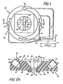
- Fig. 1 is a plan view of a reflectometer constructed in accordance with the invention, with certain parts shown schematically;
- Fig. 2a is a section view, taken generally along the line II-II of Fig. 1;
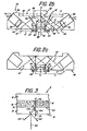
- Fig. 2b is a view similar to Fig. 2a, but with section lines removed and light beam paths added;
- Fig. 2c is a view similar to Fig. 2b, with lines omitted to show the relationship between certain distances discussed herein;
- Fig. 3 is a view showing the layers of a test element adapted to be used with the reflectometer of the present invention;
- Fig. 4 is a view similar to that of Fig. 2b, but illustrating an alternative embodiment; and
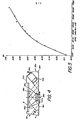
- Fig. 5 is a graph of concentration versus reflection density, the density values having been obtained using the reflectometer of the present invention.
- The term "specular reflection" is used herein in its conventional meaning, that is, reflection in which "the directions of the incident and reflected radiation make equal angles with a line perpendicular to the reflecting surface [usually called the 'normal']", McGraw-Hill Dictionary of Scientific and Technical Terms (1969). Therefore, specular reflection is generally to be distinguished from diffuse reflection which occurs at all angles rather than just the angle of incidence.
- The present invention can be practised using different wavelengths of radiation, including radiation not in the visible range; thus, terms such as "light" and "illuminate" as used herein, are not limited to visible radiation.
- The specific embodiments of the present invention hereinafter described are particularly adapted to be used as portable instruments for the detection of analytes in biological liquids such as serum. In addition, the present invention is useful to test liquids other than biological liquids, for example, industrial liquids; it is also useful to detect various color densities in non-biologic test elements, for example, photographic prints.
- With reference to Figs. 1 and 2a, there is shown a
reflectometer 30 which comprises ahousing 32, asource 34 of illuminating radiation having alens 35, and a detector means such as aphotodetector 36. As shown in Fig. 1,reflectometer 30 incudes foursources 34. Eachsource 34 has -- different wavelength of emission.Housing 32 is constructed of optically transmissive material. Various optically transmissive plastics are useful in makinghousing 32, particularly ifhousing 32 is formed as a molded piece. Methyl methacrylate, available from Rohm Haas Co. under the trademark "Plexiglas," is a particularly useful material.Housing 32 is provided with asupport surface 38 adapted to support a test element E, shown in dotted lines in Fig. 2a.Support surface 38 is preferably recessed below anuppermost surface 39 ofhousing 32. - Analysis of liquids, using the present invention, is preferably accomplished through the use of generally flat test elements E (Figs. 2a, 3 and 4). The test elements E are preferably constructed as described in U.S. -A- 3,992,158. Liquid deposited on the test element E passes first into a spreading layer 14, and then into a
reagent layer 12. Layer 14 is constructed to reflect light at aninterface 18 betweenlayer 12 and layer 14, andreagent layer 12 is the locus of a reaction that generates a detectable change. U.S. -A-4,169,751, discloses one useful form of such a test element.Layers 12 and 14 are mounted on a transparent, liquid-impervious support 10, and thelayers 12, 14, andsupport 10 are mounted in aplastic frame 15. -
Support 10 of test element E comprises anexterior surface 16 which is the primary locus of specular reflection; however,surface 16 is not the only such locus. Specular reflection also occurs at aninterface 20 located between thesupport 10 and the reagent layer 12 (Fig. 3). - For any given amount of
radiation 100 that impinges onto thesurface 16 ofsupport 10 at point A, there is a small fraction ofspecular reflection 102;radiation 100 andspecular reflection 102 make equal angles with anaxis 101 which is the normal tosurface 16. There is essentially no detectable diffuse reflection from point A, by reason of the high degree of transparency of thesupport 10. Most of theradiation 100 striking point A passes throughsupport 10 and strikesinterface 20 at a point B. Because there is never a perfect match of indices of refraction ofsupport 10 andlayer 12, there is somespecular reflection 104 frominterface 20 along with a small amount ofdiffuse reflection 106. Radiation not reflected at point B attempts to traversereagent layer 12 to a point C atinterface 18 betweenlayers 12 and 14. Because the spreading layer 14 is highly reflective, little radiation proceeds beyond point C. Most of the radiation at point C is reflected asdiffuse reflection 110. As the radiation passes from point B to point C and from point C back throughlayer 12, it traversesparticles 19 oflayer 12. To the extent thatparticles 19 are radiation-absorbing dye, thediffuse reflection 110 is reduced proportionately. It is thisdiffuse reflection 110 that is detected and which is an indication of the amount of analyse that is present.Specular reflection 102 andspecular reflection 104 never traverse thedye particles 19 oflayer 12 and, for best results, must be excluded from detection. There may be a slight amount ofspecular reflection 112 at point C, but this reflection can be ignored since it is not likely that it will get past the light-absorbingdye particles 19. -
Housing 32 is provided with areceptacle 40 for eachsource 34 and anopening 42 which is adapted to receive thephotodetector 36. Preferably,receptacles 40 are cylindrical with generally planar ends 43 (Fig. 2b), eachreceptacle 40 being sized to receive asource 34 therein. - Each
source 34 is preferably a light-emitting diode (LED) provided with a spherical lens 35 (Fig. 2b) that partially collimates the emitted light into a generallycylindrical light beam 47 having an axis 48. It will be appreciated that the more complete the collimation ofbeam 47, the more readily it can be controlled in the manner described herein. An example of an LED that is useful for asource 34 is available from So Li Co. under the designation ESBR/SBR 5501. - Ends 43 of
receptacles 40 need only be generally flat and only generally perpendicular to axis 48 ofbeam 47. Thus, slight surface depressions (not shown) are easily tolerated inends 43, and theends 43 are useful even if they deviate as much as 5° from a plane perpendicular to axis 48. Ends 43 are not curved to conform to the surface oflens 35, since this would tend to scatter the collimated light fromsource 34. -
Opening 42 has anaxis 45 and is divided into alower portion 44 and anupper portion 46.Lower portion 44 is preferably cylindrical and sized to receive thephotodetector 36.Upper portion 46 ofopening 42 has a generally frusto-conical surface 49, with planar facets 50 (Fig. 1) formed on thesurface 49;facets 50 provide a more uniform emission of radiation from thehousing 32 than would occur from a conical surface. Most preferably,beam 47 exits fromfacets 50 at an angle of; or of about, 0° thereto.Photodateutor 36 may be a photodiode, available from Vactec, Inc., under the designation VTB 1113. -
Housing 32 includes areflective surface 56, operatively disposed to reflect the beam 47 (Fig. 2b) fromsource 34. As is well known in the art, ifsurface 56 is sufficiently smooth, total internal reflection ofbeam 47 can be obtained.Surface 56 can also be provided with a laminated reflective material (not shown) such as a metal foil. If the smoothness ofsurface 56 is relied on to obtain the desired internal reflection, :ngle a, the angle ofbeam 47 to surface 56, is selected in accordance with the index of refraction for the optically transmissivematerial forming housing 32. For the preferred material, methyl methacrylate, angle a is no more than about 47.8° to ensure that the light is internally reflected from, rather than emitted out of,surface 56. Most preferably, angle a is about 40° for methyl methacrylate. The reflectivity ofsurface 56 is not adversely affected by contact with most other surfaces. However,surface 56 must not contact a material that both wets surface 56 and has a higher index of refraction, e.g., a piece of adhesive tape (not shown), since thebeam 47 will tend to leak into that material instead of being reflected therefrom. - Although
light beam 47 is partially collimated bylens 35, a small fraction of thebeam 47 may flare out along a path X (Fig. 2b). To avoid detection of light along path X, ashield 60 is positioned aroundphotodetector 36. Aportion 62 of theshield 60 is of a height sufficient to block light along path X, but not of a height sufficient to blockbeam 47 from reaching element E. An end surface 63 ofportion 62 is beveled to coincide generally with thesurface 49 ofupper receptacle portion 46. -
Beam 47 impinges upon test element E to illuminate a spot area S (Fig. 2b) at an angle toaxis 45 which is (900-a), and a specular reflection beam 47' extends from element E at the same angle (90° -a) toaxis 45. Beam 47' reflects offsurface 56 at area S' (Fig. 2b). Asource 34 in an inactivated state, placed diametrically opposite an activatedsource 34, is particularly useful to trap the specular reflection beam 47'. Beam 47' is not detected byphotodetector 36 becausephotodetector 36 detects diffuse reflected light from area S of element E as a conical beam confined inside of the generally frusto-conical surface 49. As is apparent from Fig. 2b, all of beam 47' passes outside the detection range ofphotodetector 36. The path of beam 47' is controlled by the partial collimation ofbeam 47 and by the path ofbeam 47. The distance of a reflection point Y of axis 48 on surface 56 (Fig. 2b) fromphotodetector 36 varies with the divergence, if any, ofbeam 47, as well as with the dimensions of the frusto-conical surface 49, and a distance Z of theshield portion 62 of thephotodetector 36 from test element E. Thus, the less the distance Z, the less the distance between reflection point Y andphotodetector 36 must be for a given angle α. - Assuming that
photodetector 36 is generally centered on spot S (Fig. 2b) a useful approximation of the relationship between distance Z and angle a, apparent from Fig. 2c, is (1) Z . w tan a wherein a and Z are as described above, and w is the outside diameter ofportion 62 ofshield 60. The distance "a" from the outer edge F of spot S" to the inwardly-extendingshield portion 62 is adjusted so thatbeams 47 and 47' justclear shield portion 62. -
Reflectometer 30 comprises amicrocomputer 70 for processing the signals from photodetector 36 (Fig. 1).Microcomputer 70 is connected to eachsource 34 and tophotodetector 36 by means ofconnectors 74. Test results are fed frommicrocomputer 70 to adisplay 72.Microcomputer 70 anddisplay 72 are of conventional design, and thus, no further description is considered necessary. - The manner in which the thickness of
reflectometer 30 is minimized will be apparent from the foregoing discussion. Since the light from asource 34 is folded inhousing 32, eachsource 34 can be mounted entirely within thehousing 32. In the most preferred embodiment,source 34 does not add to the thickness ofreflectometer 30. Thus, thereflectometer 30 has a thickness fromsurface 39 to surface 56 that does not exceed about 1 cm. In contrast, if eachsource 34 were to be mounted through surface 56 (not shown), the thickness of thereflectometer 30 would be increased about 30%. - In Fig. 4, there is illustrated an alternative embodiment in which specular reflection directed out of a reflectometer 30a. Reflectometer 30a comprises a housing 32a constructed of an optically transmissive material, a source 34a mounted in a receptacle 40a, and a photodetector 36a mounted in an opening 42a. In reflectometer 30a, a
side surface 80 of housing 32a is located directly opposite source 34a;surface 80 is inclined at an angle tc a surface 56a. The value of B is selected to ensure that a specular reflection beam 47a.' exits out ofsurface 80, rather than reflecting from thesurface 80. The particular value of B will depend upon the index of refraction for the optically transmissive material of housing 32a. In the case of methyl methacrylate, β is preferably less than 92°, and most preferably about 75°. A value greater than 92° for β is undesirable because the specular reflectance beam 47a' would be internally reflected and could be detected by photodetector 36a. - A test element E may be supported by a support surface 38a, which is recessed below an uppermost surface 39a of the housing 32a. A shield 60a is positioned around photodetector 36a.
- Test elements constructed as described in U.S. -A- 3,992,158, were spotted with calibrator liquids containing twelve different known levels of glucose concentration. The density DR of each test element was measured, using a reflectometer constructed as shown in Figs. 1 and 2b. In Fig. 5, there is shown a calibrator curve formed by plotting the measured densities DR against the known glucose concentrations, demonstrating that a proportionally increased density was detected for each increased concentration of glucose.
Claims (11)
Z = w tan a
wherein w is the outside diameter of said shield means (60; 60a) and a is the angle at which said radiation is reflected from said reflective surface (56; 56a).
Applications Claiming Priority (2)
| Application Number | Priority Date | Filing Date | Title |
|---|---|---|---|
| US401754 | 1982-07-26 | ||
| US06/401,754 US4518259A (en) | 1982-07-26 | 1982-07-26 | Light guide reflectometer |
Publications (3)
| Publication Number | Publication Date |
|---|---|
| EP0102189A2 true EP0102189A2 (en) | 1984-03-07 |
| EP0102189A3 EP0102189A3 (en) | 1984-11-07 |
| EP0102189B1 EP0102189B1 (en) | 1987-08-19 |
Family
ID=23589101
Family Applications (1)
| Application Number | Title | Priority Date | Filing Date |
|---|---|---|---|
| EP83304308A Expired EP0102189B1 (en) | 1982-07-26 | 1983-07-26 | Reflectometer |
Country Status (5)
| Country | Link |
|---|---|
| US (1) | US4518259A (en) |
| EP (1) | EP0102189B1 (en) |
| JP (1) | JPS5943333A (en) |
| CA (1) | CA1179524A (en) |
| DE (1) | DE3373146D1 (en) |
Cited By (4)
| Publication number | Priority date | Publication date | Assignee | Title |
|---|---|---|---|---|
| EP0177861A2 (en) * | 1984-10-10 | 1986-04-16 | Miles Inc. | Readhead with reduced height sensitivity |
| EP0205698A1 (en) * | 1985-06-28 | 1986-12-30 | EASTMAN KODAK COMPANY (a New Jersey corporation) | Compact reflectometer |
| EP0762110A1 (en) * | 1995-09-05 | 1997-03-12 | Bayer Corporation | Diffused light reflectance readhead |
| DE102008009213A1 (en) * | 2008-02-15 | 2009-08-27 | Perkinelmer Optoelectronics Gmbh & Co.Kg | Radiation conductor, detector, manufacturing process |
Families Citing this family (25)
| Publication number | Priority date | Publication date | Assignee | Title |
|---|---|---|---|---|
| DE3407754A1 (en) * | 1984-03-02 | 1985-09-12 | Boehringer Mannheim Gmbh, 6800 Mannheim | DEVICE FOR DETERMINING THE DIFFUSION REFLECTIVITY OF A SAMPLE AREA OF SMALL DIMENSIONS |
| US4755058A (en) * | 1984-06-19 | 1988-07-05 | Miles Laboratories, Inc. | Device and method for measuring light diffusely reflected from a nonuniform specimen |
| US4606645A (en) * | 1984-10-29 | 1986-08-19 | Weyerhaeuser Company | Method for determining localized fiber angle in a three dimensional fibrous material |
| JPS61116645A (en) * | 1984-11-09 | 1986-06-04 | Nippon Denso Co Ltd | Liquid detector for automatic windshield wiper controller |
| US4935346A (en) | 1986-08-13 | 1990-06-19 | Lifescan, Inc. | Minimum procedure system for the determination of analytes |
| DE3914037A1 (en) * | 1989-04-28 | 1990-10-31 | Boehringer Mannheim Gmbh | TEST CARRIER ANALYZER |
| US5303037A (en) * | 1992-02-24 | 1994-04-12 | Eaton Corporation | Color sensor illumination source employing a lightpipe and multiple LEDs |
| US5837546A (en) * | 1993-08-24 | 1998-11-17 | Metrika, Inc. | Electronic assay device and method |
| US5625459A (en) * | 1995-03-03 | 1997-04-29 | Galileo Electro-Optics Corporation | Diffuse reflectance probe |
| CA2250400A1 (en) * | 1996-04-30 | 1997-11-06 | Metrika, Inc. | Method and device for measuring reflected optical radiation |
| US5892808A (en) * | 1996-06-28 | 1999-04-06 | Techne Systems, Inc. | Method and apparatus for feature detection in a workpiece |
| US20050101032A1 (en) * | 1997-02-10 | 2005-05-12 | Metrika, Inc. | Assay device, composition, and method of optimizing assay sensitivity |
| JPH11271217A (en) * | 1998-03-20 | 1999-10-05 | Hoechst Reseach & Technology Kk | Optical sensor |
| US6272437B1 (en) | 1998-04-17 | 2001-08-07 | Cae Inc. | Method and apparatus for improved inspection and classification of attributes of a workpiece |
| US20060019404A1 (en) * | 1998-05-06 | 2006-01-26 | Blatt Joel M | Quantitative assay with extended dynamic range |
| NL1011147C2 (en) * | 1999-01-27 | 2000-07-31 | Spectrostar B V | Reflectometer. |
| US6458326B1 (en) | 1999-11-24 | 2002-10-01 | Home Diagnostics, Inc. | Protective test strip platform |
| US6483590B1 (en) * | 2000-12-18 | 2002-11-19 | The Boeing Company | Instrument for rapidly characterizing material reflectance properties |
| US6562625B2 (en) | 2001-02-28 | 2003-05-13 | Home Diagnostics, Inc. | Distinguishing test types through spectral analysis |
| US6541266B2 (en) | 2001-02-28 | 2003-04-01 | Home Diagnostics, Inc. | Method for determining concentration of an analyte in a test strip |
| US6525330B2 (en) | 2001-02-28 | 2003-02-25 | Home Diagnostics, Inc. | Method of strip insertion detection |
| EP1590655A1 (en) * | 2002-10-23 | 2005-11-02 | Sentronic GmbH Gesellschaft für Optische Messsysteme | Optical sensor |
| US7150995B2 (en) * | 2004-01-16 | 2006-12-19 | Metrika, Inc. | Methods and systems for point of care bodily fluid analysis |
| US20050227370A1 (en) * | 2004-03-08 | 2005-10-13 | Ramel Urs A | Body fluid analyte meter & cartridge system for performing combined general chemical and specific binding assays |
| US8664681B2 (en) * | 2012-07-06 | 2014-03-04 | Invensas Corporation | Parallel plate slot emission array |
Citations (3)
| Publication number | Priority date | Publication date | Assignee | Title |
|---|---|---|---|---|
| US3500054A (en) * | 1966-11-25 | 1970-03-10 | Alcatel Sa | Controlled uniform illumination and sensing of objects having differential light reflectivity |
| US3536927A (en) * | 1968-10-17 | 1970-10-27 | Scient Advances Inc | Light and photocell unit for sorting apparatus |
| US3910701A (en) * | 1973-07-30 | 1975-10-07 | George R Henderson | Method and apparatus for measuring light reflectance absorption and or transmission |
Family Cites Families (14)
| Publication number | Priority date | Publication date | Assignee | Title |
|---|---|---|---|---|
| US3602213A (en) * | 1968-02-13 | 1971-08-31 | Prototypes Inc | Apparatus for photoelectric dermachromography |
| US3676690A (en) * | 1971-01-04 | 1972-07-11 | Westinghouse Learning Corp | Reflected light document reading head |
| US3709612A (en) * | 1971-03-10 | 1973-01-09 | Miles Lab | Apparatus for measuring reflected light under stabilized light source conditions |
| US3786238A (en) * | 1972-09-05 | 1974-01-15 | Addressograph Multigraph | Optical reader |
| US3992158A (en) * | 1973-08-16 | 1976-11-16 | Eastman Kodak Company | Integral analytical element |
| US4033698A (en) * | 1975-10-10 | 1977-07-05 | International Business Machines Corporation | Apparatus for textile color analysis |
| US3999864A (en) * | 1975-11-17 | 1976-12-28 | International Business Machines Corporation | Gloss measuring instrument |
| US4224032A (en) * | 1976-12-17 | 1980-09-23 | Eastman Kodak Company | Method and apparatus for chemical analysis |
| US4219529A (en) * | 1977-11-28 | 1980-08-26 | Eastman Kodak Company | Incubator for chemical analyzer |
| JPS553704U (en) * | 1978-06-21 | 1980-01-11 | ||
| US4211469A (en) * | 1978-09-05 | 1980-07-08 | The Deutsch Company Electronic Components Division | Optical coupling device |
| US4239393A (en) * | 1978-10-13 | 1980-12-16 | Tobias Philip E | Optical density scanning head |
| US4282560A (en) * | 1979-01-15 | 1981-08-04 | A.C.A. Products, Inc. | Light distributor |
| US4246489A (en) * | 1979-04-16 | 1981-01-20 | Tokyo Shibaura Electric Co., Ltd. | Liquid level detector for detecting a liquid level when reaching a prescribed height |
-
1982
- 1982-07-26 US US06/401,754 patent/US4518259A/en not_active Expired - Fee Related
- 1982-11-17 CA CA000415757A patent/CA1179524A/en not_active Expired
-
1983
- 1983-07-26 JP JP58136687A patent/JPS5943333A/en active Pending
- 1983-07-26 DE DE8383304308T patent/DE3373146D1/en not_active Expired
- 1983-07-26 EP EP83304308A patent/EP0102189B1/en not_active Expired
Patent Citations (3)
| Publication number | Priority date | Publication date | Assignee | Title |
|---|---|---|---|---|
| US3500054A (en) * | 1966-11-25 | 1970-03-10 | Alcatel Sa | Controlled uniform illumination and sensing of objects having differential light reflectivity |
| US3536927A (en) * | 1968-10-17 | 1970-10-27 | Scient Advances Inc | Light and photocell unit for sorting apparatus |
| US3910701A (en) * | 1973-07-30 | 1975-10-07 | George R Henderson | Method and apparatus for measuring light reflectance absorption and or transmission |
Cited By (6)
| Publication number | Priority date | Publication date | Assignee | Title |
|---|---|---|---|---|
| EP0177861A2 (en) * | 1984-10-10 | 1986-04-16 | Miles Inc. | Readhead with reduced height sensitivity |
| EP0177861A3 (en) * | 1984-10-10 | 1986-07-23 | Miles Laboratories, Inc. | Readhead with reduced height sensitivity |
| EP0205698A1 (en) * | 1985-06-28 | 1986-12-30 | EASTMAN KODAK COMPANY (a New Jersey corporation) | Compact reflectometer |
| EP0762110A1 (en) * | 1995-09-05 | 1997-03-12 | Bayer Corporation | Diffused light reflectance readhead |
| DE102008009213A1 (en) * | 2008-02-15 | 2009-08-27 | Perkinelmer Optoelectronics Gmbh & Co.Kg | Radiation conductor, detector, manufacturing process |
| DE102008009213B4 (en) * | 2008-02-15 | 2010-09-02 | Perkinelmer Optoelectronics Gmbh & Co.Kg | Radiation conductor, detector, manufacturing process |
Also Published As
| Publication number | Publication date |
|---|---|
| US4518259A (en) | 1985-05-21 |
| DE3373146D1 (en) | 1987-09-24 |
| JPS5943333A (en) | 1984-03-10 |
| EP0102189B1 (en) | 1987-08-19 |
| CA1179524A (en) | 1984-12-18 |
| EP0102189A3 (en) | 1984-11-07 |
Similar Documents
| Publication | Publication Date | Title |
|---|---|---|
| EP0102189B1 (en) | Reflectometer | |
| EP0299314B1 (en) | Readhead for reflectance measurement of distant samples | |
| US4703182A (en) | Arrangement for fluorescence-optical measurement of concentrations of substances contained in a sample | |
| KR100816799B1 (en) | Test element analysis system and method for analytical investigation using the same | |
| US4810658A (en) | Photometric instruments, their use in methods of optical analysis, and ancillary devices therefor | |
| EP0127418B1 (en) | Equipment for the measurement of fluorescence, turbidity, luminescence, or absorption | |
| US4816670A (en) | Optical measuring head | |
| CA2184313A1 (en) | Diffused light reflectance readhead | |
| EP0601205B1 (en) | Optical measurement instrument | |
| CA2184310A1 (en) | Diffused light reflectance readhead | |
| JPH11258150A (en) | Medical diagnosis apparatus using fresnel reflecting body | |
| JPH10267833A (en) | Reading head of photometric diagnosing apparatus | |
| US6507402B2 (en) | SPR sensor plate and immune reaction measuring instrument using the same | |
| US5039225A (en) | Apparatus for measurement of reflection density | |
| US5155628A (en) | Optical transmission spectrometer | |
| US4930865A (en) | Optical transmission spectrometer | |
| CA1241212A (en) | Readhead with reduced height sensitivity | |
| EP0806651B1 (en) | Reflectance spectroscope with read head for minimizing singly-reflected light rays | |
| WO1983000931A1 (en) | Method and apparatus for detecting sample fluid | |
| GB2115175A (en) | Fibre optics head featuring core spacing to block specular reflection | |
| CA1201299A (en) | Optical readhead | |
| US4660984A (en) | Reflectometer featuring an integrated cavity of enhanced efficiency | |
| EP0174186B1 (en) | Reflectometer | |
| SU1672209A1 (en) | Method of measuring the thickness of transparent plates with diffusing surface | |
| CN112924419A (en) | Light source component and specific protein analysis system |
Legal Events
| Date | Code | Title | Description |
|---|---|---|---|
| PUAI | Public reference made under article 153(3) epc to a published international application that has entered the european phase |
Free format text: ORIGINAL CODE: 0009012 |
|
| AK | Designated contracting states |
Designated state(s): DE FR GB |
|
| PUAL | Search report despatched |
Free format text: ORIGINAL CODE: 0009013 |
|
| AK | Designated contracting states |
Designated state(s): DE FR GB |
|
| 17P | Request for examination filed |
Effective date: 19850415 |
|
| 17Q | First examination report despatched |
Effective date: 19860917 |
|
| GRAA | (expected) grant |
Free format text: ORIGINAL CODE: 0009210 |
|
| AK | Designated contracting states |
Kind code of ref document: B1 Designated state(s): DE FR GB |
|
| REF | Corresponds to: |
Ref document number: 3373146 Country of ref document: DE Date of ref document: 19870924 |
|
| ET | Fr: translation filed | ||
| PLBE | No opposition filed within time limit |
Free format text: ORIGINAL CODE: 0009261 |
|
| STAA | Information on the status of an ep patent application or granted ep patent |
Free format text: STATUS: NO OPPOSITION FILED WITHIN TIME LIMIT |
|
| 26N | No opposition filed | ||
| PGFP | Annual fee paid to national office [announced via postgrant information from national office to epo] |
Ref country code: GB Payment date: 19910619 Year of fee payment: 9 |
|
| PGFP | Annual fee paid to national office [announced via postgrant information from national office to epo] |
Ref country code: FR Payment date: 19910710 Year of fee payment: 9 Ref country code: DE Payment date: 19910710 Year of fee payment: 9 |
|
| PG25 | Lapsed in a contracting state [announced via postgrant information from national office to epo] |
Ref country code: GB Effective date: 19920726 |
|
| GBPC | Gb: european patent ceased through non-payment of renewal fee |
Effective date: 19920726 |
|
| PG25 | Lapsed in a contracting state [announced via postgrant information from national office to epo] |
Ref country code: FR Effective date: 19930331 |
|
| PG25 | Lapsed in a contracting state [announced via postgrant information from national office to epo] |
Ref country code: DE Effective date: 19930401 |
|
| REG | Reference to a national code |
Ref country code: FR Ref legal event code: ST |