EP0101064A1 - Strap guide for strap adjustment assembly - Google Patents
Strap guide for strap adjustment assembly Download PDFInfo
- Publication number
- EP0101064A1 EP0101064A1 EP83107896A EP83107896A EP0101064A1 EP 0101064 A1 EP0101064 A1 EP 0101064A1 EP 83107896 A EP83107896 A EP 83107896A EP 83107896 A EP83107896 A EP 83107896A EP 0101064 A1 EP0101064 A1 EP 0101064A1
- Authority
- EP
- European Patent Office
- Prior art keywords
- ribs
- strap guide
- wing
- strap
- needle
- Prior art date
- Legal status (The legal status is an assumption and is not a legal conclusion. Google has not performed a legal analysis and makes no representation as to the accuracy of the status listed.)
- Granted
Links
Images

Classifications
-
- A—HUMAN NECESSITIES
- A42—HEADWEAR
- A42B—HATS; HEAD COVERINGS
- A42B7/00—Fastening means for head coverings; Elastic cords; Ladies' hat fasteners
-
- A—HUMAN NECESSITIES
- A41—WEARING APPAREL
- A41F—GARMENT FASTENINGS; SUSPENDERS
- A41F15/00—Shoulder or like straps
- A41F15/002—Shoulder or like straps separable or adjustable
-
- A—HUMAN NECESSITIES
- A41—WEARING APPAREL
- A41H—APPLIANCES OR METHODS FOR MAKING CLOTHES, e.g. FOR DRESS-MAKING OR FOR TAILORING, NOT OTHERWISE PROVIDED FOR
- A41H37/00—Machines, appliances or methods for setting fastener-elements on garments
- A41H37/08—Setting buckles
-
- A—HUMAN NECESSITIES
- A42—HEADWEAR
- A42B—HATS; HEAD COVERINGS
- A42B1/00—Hats; Caps; Hoods
- A42B1/22—Hats; Caps; Hoods adjustable in size ; Form-fitting or self adjusting head coverings; Devices for reducing hat size
-
- A—HUMAN NECESSITIES
- A44—HABERDASHERY; JEWELLERY
- A44B—BUTTONS, PINS, BUCKLES, SLIDE FASTENERS, OR THE LIKE
- A44B11/00—Buckles; Similar fasteners for interconnecting straps or the like, e.g. for safety belts
- A44B11/02—Buckles; Similar fasteners for interconnecting straps or the like, e.g. for safety belts frictionally engaging surface of straps
- A44B11/04—Buckles; Similar fasteners for interconnecting straps or the like, e.g. for safety belts frictionally engaging surface of straps without movable parts
-
- Y—GENERAL TAGGING OF NEW TECHNOLOGICAL DEVELOPMENTS; GENERAL TAGGING OF CROSS-SECTIONAL TECHNOLOGIES SPANNING OVER SEVERAL SECTIONS OF THE IPC; TECHNICAL SUBJECTS COVERED BY FORMER USPC CROSS-REFERENCE ART COLLECTIONS [XRACs] AND DIGESTS
- Y10—TECHNICAL SUBJECTS COVERED BY FORMER USPC
- Y10T—TECHNICAL SUBJECTS COVERED BY FORMER US CLASSIFICATION
- Y10T24/00—Buckles, buttons, clasps, etc.
- Y10T24/40—Buckles
- Y10T24/4088—One-piece
- Y10T24/4093—Looped strap
-
- Y—GENERAL TAGGING OF NEW TECHNOLOGICAL DEVELOPMENTS; GENERAL TAGGING OF CROSS-SECTIONAL TECHNOLOGIES SPANNING OVER SEVERAL SECTIONS OF THE IPC; TECHNICAL SUBJECTS COVERED BY FORMER USPC CROSS-REFERENCE ART COLLECTIONS [XRACs] AND DIGESTS
- Y10—TECHNICAL SUBJECTS COVERED BY FORMER USPC
- Y10T—TECHNICAL SUBJECTS COVERED BY FORMER US CLASSIFICATION
- Y10T24/00—Buckles, buttons, clasps, etc.
- Y10T24/47—Strap-end-attaching devices
- Y10T24/4736—Buckle connected
Definitions
- the present invention relates generally to a strap adjustment assembly for adjustably interconnecting the edges of a garment, bag, cap or the like by means of a strap or belt, and more particularly to a strap guide for use in such a strap adjustment assembly.
- Such known strap adjustment assemblies generally comprising a strap guide of hollow rectangular shape mounted on one of the edges of the article and guiding around its one bar an end portion of a first strap which is secured at another end to the other edge of the article.
- the rectangular strap guide is attached to one end of a second strap by looping the end around another bar of the guide and sewn to itself, and then the second strap is sewn to the one edge of the article.
- the known strap guide thus arranged is difficult to attach by sewing to the article.
- the present invention seeks to provide a strap guide for strap adjustment assemblies which can be attached by sewing to an article with utmost ease.
- the present invention further seeks to provide a strap guide having means attachable by being sewn directly to an article.
- the present invention further seeks to provide a strap guide which is inexpensive to manufacture and can be colored as desired to meet user's various color preferences.
- a strap guide of synthetic resin for a strap adjustment assembly comprising a hollow rectangular frame having an opening therein, and a wing integral with said frame and extending laterally away from said opening, said wing having a plurality of needle-penetratable portions spaced one another at equal intervals.
- the strap guide 11 is molded of synthetic resin and comprises a hollow frame 12 of a substantially rectangular shape and a rectangular wing 13 integral with the the frame 12.
- the frame 12 has a pair of parallel spaced guide and support bars 14, 15 and a pair of parallel spaced connecting rods 16, 17 interconnecting the bars 14, 16, the bars 14, 15 being larger in length than the rods 16, 17.
- the bars 14, 15 and the rods 16, 17 jointly define therebetween a rectangular opening 18 for the passage therethrough of a belt or strap (not shown).
- the belt is turned over to form a loop around the guide bar 14 as described below.
- the rods 16 are thicker than the bars 14, 15 and have respective front surfaces 19 extending arcuately between the bars 14, 15.
- the wing 13 has a substantially hollow rectangular peripheral portion 20 and a central web portion 21 surrounded by the peripheral portion 20.
- the peripheral portion 20 includes a base 22 joined with the support bar 15, a pair of parallel spaced legs 23, 24 joined at one ends with the opposite ends of the base 22 and extending away from the support bar 15, and a connecting rod 25 interconnecting the other ends of the legs 23, 24.
- the central web portion 21 includes a plurality of parallel spaced ribs 26 extending obliquely across the web portion 21 and a plurality of slots 27 extending between two adjacent ones of the ribs 26, the slots 27 constituting needle-penetratable portions as described below.
- the wing 13 is thinner than the bars 14, 15 of the frame 12, and both the frame and wing 12 and 13 have respective rear surfaces 28, 29 lying flash with each other.
- the ribs 26 have a simi-circular transverse cross section and hence have a pair of arcuate sidewalls 26a converging toward the front side of the wing 13, as shown in Figures 2 and 3.
- the strap guide 11 is attached to a first edge or cloth part 30 of a cap 31 as shown in Figures 4 to 6.
- the wing 13 is placed between a pair of front and rear cloths 30a, 30b ( Figures 5 and 6) of the cap 31 with the front surface of the guide 11 facing upwardly. Then, the wing 13 is secured by a pair of rows of stitches 32 to the the first cloth part 30 of the cap 31.
- a pair of sewing needles (not shown) penetrate the front and rear cloths 30a, 30b successively through grooves 27 so that each stitch or loop 32a encircles one of the ribs 26 as shown in Figure 6.
- each of the sewing needles while being driven is guided by one of the arcuate sidewalls 26a into adjacent one of the grooves 27 even when the needle and the groove 27 are not in registry with each other. Further, each row of stitches passes across the wing 13 at an angle to the ribs 26, the strap guide 11 is held in position against displacement even when lateral forces are appliedthereto.
- a belt or strap 33 is sewn at its one end portion to a second edge or cloth part 34 of the cap 31.
- The'opposite strap end portion 35 is threaded between one of spaced outer bars 36 and a central bar 37 from the back to the face of a strap retainer 38, and then between the central bar 37 and the other outer bar 39 from the face to the back of the retainer 38.
- the strap end portion 35 is turned over to form a loop around the guide bar 14 of the frame 12 and again threaded between the bars 39, 37, 36 in the reversed sequence.
- the strap retainer 38 and the strap guide 11 jointly constitute a strap adjustment assembly.
- a modified strap guide 40 shown in Figure 7 is structurally the same as the guide 11 described above with the exception that a central web portion 41 includes a plurality of first ribs 42 extending obliquely across the web portion 41 and a plurality of second ribs 43 extending normal to the first ribs 42 across the web portion 41.
- the first and second ribs 41, 42 extend in diagonal pattern so as to define a plurality of substantially square apertures 44 between two adjacent ones of the first ribs 42 and two adjacent ones of the second ribs 43.
- the apertures 44 constitute needle-penetratable portions for the passage therethrough of sewing needles (not shown).
- Each of the ribs 42, 43 has a trapezoidal shape in transverse cross section having pair of sidewalls 45 diverging rearwardly of the web portion 41.
- the sidewalls 45 serve in the same manner as the arcuate sidewalls 26a of the ribs 26.
- the ribs 42, 43 may have a triangular cross section of which a corner is directed upwardly (not shown). It is essential that the ribs have a pair of side walls converging toward the front side of the wing from which a sewing needle is thrust in.
- Figure 8 shows another modifaction in which a plurality of parallel spaced ribs 46 extend perpendicularly between a base 47 and a connecting bar 48 of a peripheral portion 49 of a wing 50 so as to define therebetween a plurality of slots 51 for the passage therethrough of sewing needles (not shown).
- the base 47 joined with a frame 52 and the connecting bar 48 prevent stitches (not shown) from displacing off the ribs 46.
- FIG. 9 Another modified strap guide 53 shown in Figure 9 includes a plurality of first ribs 54 extending perpendicularly between a base 55 and a connecting bar 56 of a peripheral portion 57 of a wing 58 and a plurality of second ribs 59 extending perpendicularly to the first ribs 54.
- the ribs 54, 59 extend checkerwise in the wing 58 so as to define, between two adjacent ones of the first ribs 54 and two adjacent ones of the second ribs 59, a plurality of substantially square apertures 60 for the passage therethrough of sewing needles (not shown).
- Figure 10 shows a further modification in which a strap guide 61 includes a wing portion 62 having a plurality of parallel spaced ribs 63 and a plurality of needle penetratable portions 64 extending between two adjacent ones of the ribs 63.
- Each of the needle-penetratable portions 64 are formed of a film of synthetic resin, the film 64 being of a thickness such that it is readily penetratable by a sewing needle when the latter is thrust in.
- the strap guides constructed in accordance with the invention have many advantages: With the wing having a plurality of needle-penetratable portions spaced at equal intervals, the strap guide can be attached with utmost ease by sewing directly to one of the edges of an article to be adjustably interconnected. The sewing needle is introduced into the needle-penetratable portions by the guide surface on each rib adjacent to one of the needle-penetratable portions even when the needle and the needle-penetratable portion are not in registry with each other. Since the strap guide is made of synthetic resin, it can be injection-molded in large quantities and hence inexpensively, can be colored as desired to meet user's various color preferences in vogue.
Abstract
Description
- The present invention relates generally to a strap adjustment assembly for adjustably interconnecting the edges of a garment, bag, cap or the like by means of a strap or belt, and more particularly to a strap guide for use in such a strap adjustment assembly.
- Various strap adjustment assemblies have been used for adjustably joining the edges or parts of an article such as a garment, cap, bag or the like. Such known strap adjustment assemblies generally comprising a strap guide of hollow rectangular shape mounted on one of the edges of the article and guiding around its one bar an end portion of a first strap which is secured at another end to the other edge of the article. For mounting, the rectangular strap guide is attached to one end of a second strap by looping the end around another bar of the guide and sewn to itself, and then the second strap is sewn to the one edge of the article. The known strap guide thus arranged is difficult to attach by sewing to the article.
- The present invention seeks to provide a strap guide for strap adjustment assemblies which can be attached by sewing to an article with utmost ease.
- The present invention further seeks to provide a strap guide having means attachable by being sewn directly to an article.
- The present invention further seeks to provide a strap guide which is inexpensive to manufacture and can be colored as desired to meet user's various color preferences.
- According to the invention, there is provided a strap guide of synthetic resin for a strap adjustment assembly, comprising a hollow rectangular frame having an opening therein, and a wing integral with said frame and extending laterally away from said opening, said wing having a plurality of needle-penetratable portions spaced one another at equal intervals.
- Many other advantages, features and additional objects of the present invention will become manifest to those versed in the art upon making reference to the detailed description and the accompanying sheets of drawings in which preferred structural embodiments incorporating the principles of the present invention are shown by way of illustrative example.
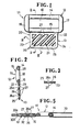
- Figure 1 is a plan view of a strap guide according to the present invention;
- Figure 2 is a cross-sectional view taken along line II - II of Figure 1;
- Figure 3 is a cross-sectional view taken along line III - III of Figure 1;
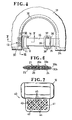
- Figure 4 is a fragmentary rear elevational view is of a cap on which/mounted a strap adjustment assembly including the strap guide shown in Figure 1;
- Figure 5 is an enlarged horizontal cross-sectional view taken along line V - V of Figure 4;
- Figure 6 is an enlarged vertical cross-sectional view taken along line VI - VI of Figure 4;
- Figure 7 is a plan view of a modified strap guide;
- Figure 8 is a view similar to Figure 7, showing another modification;
- Figure 9 is a plan view of a modified strap guide; and
- Figure 10 is a view similar to Figure 2, showing a modified strap guide.
- The principles of the present invention are particularly useful when embodied in a strap guide such as shown in Figures 1 to 3, generally indicated by the
numeral 11. - The
strap guide 11 is molded of synthetic resin and comprises ahollow frame 12 of a substantially rectangular shape and arectangular wing 13 integral with the theframe 12. - The
frame 12 has a pair of parallel spaced guide andsupport bars rods bars bars rods bars rods rectangular opening 18 for the passage therethrough of a belt or strap (not shown). The belt is turned over to form a loop around theguide bar 14 as described below. As shown in Figure 2, therods 16 are thicker than thebars respective front surfaces 19 extending arcuately between thebars - The
wing 13 has a substantially hollow rectangularperipheral portion 20 and acentral web portion 21 surrounded by theperipheral portion 20. Theperipheral portion 20 includes abase 22 joined with thesupport bar 15, a pair of parallelspaced legs base 22 and extending away from thesupport bar 15, and a connectingrod 25 interconnecting the other ends of thelegs central web portion 21 includes a plurality of parallel spacedribs 26 extending obliquely across theweb portion 21 and a plurality ofslots 27 extending between two adjacent ones of theribs 26, theslots 27 constituting needle-penetratable portions as described below. As shown in Figure 2, thewing 13 is thinner than thebars frame 12, and both the frame andwing rear surfaces ribs 26 have a simi-circular transverse cross section and hence have a pair ofarcuate sidewalls 26a converging toward the front side of thewing 13, as shown in Figures 2 and 3. - The
strap guide 11 is attached to a first edge orcloth part 30 of acap 31 as shown in Figures 4 to 6. Thewing 13 is placed between a pair of front andrear cloths cap 31 with the front surface of theguide 11 facing upwardly. Then, thewing 13 is secured by a pair of rows ofstitches 32 to the thefirst cloth part 30 of thecap 31. During which time, a pair of sewing needles (not shown) penetrate the front andrear cloths grooves 27 so that each stitch or loop 32a encircles one of theribs 26 as shown in Figure 6. - Since the
ribs 26 have thearcuate sidewalls 26a, each of the sewing needles while being driven is guided by one of thearcuate sidewalls 26a into adjacent one of thegrooves 27 even when the needle and thegroove 27 are not in registry with each other. Further, each row of stitches passes across thewing 13 at an angle to theribs 26, thestrap guide 11 is held in position against displacement even when lateral forces are appliedthereto. - In Figure 4, a belt or
strap 33 is sewn at its one end portion to a second edge orcloth part 34 of thecap 31. The'oppositestrap end portion 35 is threaded between one of spacedouter bars 36 and acentral bar 37 from the back to the face of astrap retainer 38, and then between thecentral bar 37 and the otherouter bar 39 from the face to the back of theretainer 38. Thestrap end portion 35 is turned over to form a loop around theguide bar 14 of theframe 12 and again threaded between thebars strap retainer 38 and thestrap guide 11 jointly constitute a strap adjustment assembly. - A modified
strap guide 40 shown in Figure 7 is structurally the same as theguide 11 described above with the exception that acentral web portion 41 includes a plurality offirst ribs 42 extending obliquely across theweb portion 41 and a plurality ofsecond ribs 43 extending normal to thefirst ribs 42 across theweb portion 41. The first andsecond ribs square apertures 44 between two adjacent ones of thefirst ribs 42 and two adjacent ones of thesecond ribs 43. Theapertures 44 constitute needle-penetratable portions for the passage therethrough of sewing needles (not shown). Each of theribs sidewalls 45 diverging rearwardly of theweb portion 41. Thesidewalls 45 serve in the same manner as thearcuate sidewalls 26a of theribs 26. Theribs - Figure 8 shows another modifaction in which a plurality of parallel spaced
ribs 46 extend perpendicularly between abase 47 and a connectingbar 48 of aperipheral portion 49 of awing 50 so as to define therebetween a plurality ofslots 51 for the passage therethrough of sewing needles (not shown). Thebase 47 joined with aframe 52 and the connectingbar 48 prevent stitches (not shown) from displacing off theribs 46. - Another modified
strap guide 53 shown in Figure 9 includes a plurality offirst ribs 54 extending perpendicularly between abase 55 and a connectingbar 56 of aperipheral portion 57 of awing 58 and a plurality ofsecond ribs 59 extending perpendicularly to thefirst ribs 54. Theribs wing 58 so as to define, between two adjacent ones of thefirst ribs 54 and two adjacent ones of thesecond ribs 59, a plurality of substantiallysquare apertures 60 for the passage therethrough of sewing needles (not shown). - Figure 10 shows a further modification in which a
strap guide 61 includes awing portion 62 having a plurality of parallel spacedribs 63 and a plurality of needlepenetratable portions 64 extending between two adjacent ones of theribs 63. Each of the needle-penetratable portions 64 are formed of a film of synthetic resin, thefilm 64 being of a thickness such that it is readily penetratable by a sewing needle when the latter is thrust in. - The strap guides constructed in accordance with the invention have many advantages: With the wing having a plurality of needle-penetratable portions spaced at equal intervals, the strap guide can be attached with utmost ease by sewing directly to one of the edges of an article to be adjustably interconnected. The sewing needle is introduced into the needle-penetratable portions by the guide surface on each rib adjacent to one of the needle-penetratable portions even when the needle and the needle-penetratable portion are not in registry with each other. Since the strap guide is made of synthetic resin, it can be injection-molded in large quantities and hence inexpensively, can be colored as desired to meet user's various color preferences in vogue.
Claims (13)
Applications Claiming Priority (2)
| Application Number | Priority Date | Filing Date | Title |
|---|---|---|---|
| JP122728/82U | 1982-08-12 | ||
| JP1982122728U JPS5928308U (en) | 1982-08-12 | 1982-08-12 | Flat ring for belt adjuster |
Publications (2)
| Publication Number | Publication Date |
|---|---|
| EP0101064A1 true EP0101064A1 (en) | 1984-02-22 |
| EP0101064B1 EP0101064B1 (en) | 1986-07-30 |
Family
ID=14843111
Family Applications (1)
| Application Number | Title | Priority Date | Filing Date |
|---|---|---|---|
| EP83107896A Expired EP0101064B1 (en) | 1982-08-12 | 1983-08-10 | Strap guide for strap adjustment assembly |
Country Status (11)
| Country | Link |
|---|---|
| US (1) | US4520533A (en) |
| EP (1) | EP0101064B1 (en) |
| JP (1) | JPS5928308U (en) |
| KR (1) | KR850002442Y1 (en) |
| AU (1) | AU538192B2 (en) |
| CA (1) | CA1211903A (en) |
| DE (2) | DE3364946D1 (en) |
| ES (1) | ES273958Y (en) |
| GB (1) | GB2126469B (en) |
| HK (1) | HK76288A (en) |
| SG (1) | SG101287G (en) |
Cited By (1)
| Publication number | Priority date | Publication date | Assignee | Title |
|---|---|---|---|---|
| EP1680972A1 (en) * | 2005-01-18 | 2006-07-19 | Illinois Tool Works Inc. | Attachment device |
Families Citing this family (18)
| Publication number | Priority date | Publication date | Assignee | Title |
|---|---|---|---|---|
| US4778082A (en) * | 1985-05-03 | 1988-10-18 | Vernon K. Vitelle | Collapsible tube squeezing device |
| JPH0424971Y2 (en) * | 1986-08-02 | 1992-06-15 | ||
| US4958758A (en) * | 1987-10-19 | 1990-09-25 | Tipple Jerome E | Multi-looped cane retaining strap |
| US5839171A (en) * | 1997-05-15 | 1998-11-24 | Tyrrell; Anthony C. | Strap anchoring means |
| US6195849B1 (en) * | 1999-02-26 | 2001-03-06 | Haun Drop Forge Co. Ltd. | Dielectric D-ring |
| US6499201B2 (en) * | 2001-01-25 | 2002-12-31 | Fildan Accessories Corporation | Garment fastener especially for swimwear and lingerie |
| US7758582B2 (en) * | 2002-06-14 | 2010-07-20 | Smith & Nephew, Inc. | Device and methods for placing external fixation elements |
| US7198541B2 (en) * | 2004-04-12 | 2007-04-03 | Hbi Branded Apparel Enterprises, Llc | Brassiere strap connector |
| US7448115B2 (en) * | 2005-01-18 | 2008-11-11 | Illinois Tool Works Inc. | Modular attachment assembly |
| US20070175005A1 (en) * | 2005-07-13 | 2007-08-02 | Who Would Of Thunk It Innovations, Llc | Adjustable buckle with dual tensioning and releasable closure for joining opposite ends of an article |
| US8408150B1 (en) * | 2011-09-20 | 2013-04-02 | Tenna M. Ragan | Sewing aid |
| US9763486B2 (en) * | 2014-07-24 | 2017-09-19 | Sunday Afternoons, Inc. | Elastic sizing mechanism |
| SG10201909092SA (en) | 2015-03-31 | 2019-11-28 | Fisher & Paykel Healthcare Ltd | A user interface and system for supplying gases to an airway |
| CN114569856A (en) | 2016-08-11 | 2022-06-03 | 费雪派克医疗保健有限公司 | Collapsible catheter, patient interface and headgear connector |
| US10238161B1 (en) | 2017-09-28 | 2019-03-26 | League Of Investors, Llc | Adjustable strap for hat |
| US10238185B1 (en) * | 2017-09-28 | 2019-03-26 | League Of Investors, Llc | Adjustment strap with quick crimp nibs |
| US10973351B2 (en) * | 2018-03-26 | 2021-04-13 | Robert L Mayers | Adjustable length tablecloth retaining device |
| JP7254527B2 (en) * | 2019-01-15 | 2023-04-10 | Ykk株式会社 | annular member |
Citations (1)
| Publication number | Priority date | Publication date | Assignee | Title |
|---|---|---|---|---|
| DE3026375A1 (en) * | 1980-07-11 | 1982-02-04 | Ries Gmbh Bekleidungsverschlussfabrik, 8034 Unterpfaffenhofen | Hook and eye fastening device - is esp. for underwear, and consists of injection moulded plastics parts with bases |
Family Cites Families (21)
| Publication number | Priority date | Publication date | Assignee | Title |
|---|---|---|---|---|
| US244776A (en) * | 1881-07-26 | Sigourney wales | ||
| FR965771A (en) * | 1950-09-21 | |||
| US426523A (en) * | 1890-04-29 | Shoulder-brace and slide therefor | ||
| US975942A (en) * | 1908-07-21 | 1910-11-15 | William D Flynn | Buckle. |
| US1687370A (en) * | 1927-06-29 | 1928-10-09 | Waterbury Buckle Co | Suspender-end loop |
| US1999167A (en) * | 1932-04-20 | 1935-04-23 | Parve Products Company | Buckle |
| FR769541A (en) * | 1933-07-05 | 1934-08-28 | Fantom Grip Co | Suspender enhancements |
| US2187349A (en) * | 1938-08-20 | 1940-01-16 | William A Keys | Neckband loop |
| US2208026A (en) * | 1939-01-30 | 1940-07-16 | Goldenberg Claire | Adjustable fastening construction |
| US2269696A (en) * | 1940-06-22 | 1942-01-13 | Shaulson Joseph | Hose fastener and the like |
| US2473209A (en) * | 1947-05-22 | 1949-06-14 | Lombardi Cyrus | Buckle |
| US3112750A (en) * | 1960-07-19 | 1963-12-03 | Sobel Metal Products Inc | Garment having adjustable plastic buckle |
| GB958710A (en) * | 1962-03-15 | 1964-05-27 | Arnold Wills And Company Ltd | Improvements in baby harness |
| GB1227596A (en) * | 1968-10-23 | 1971-04-07 | ||
| DE2104143B2 (en) * | 1970-02-03 | 1972-12-28 | S.T.A.S. Societe Technique dAccessoires Specialises, Asnieres (Frankreich) | LOOSE MADE FROM A STRAP |
| DE2014007B2 (en) * | 1970-03-24 | 1976-01-22 | Daimler-Benz Ag, 7000 Stuttgart | ATTACHING A SEAT BELT TO A VEHICLE SEAT |
| GB1343131A (en) * | 1971-02-24 | 1974-01-10 | Courtaulds Ltd | Adjustable shoulder strap |
| US3799610A (en) * | 1971-10-07 | 1974-03-26 | Hollins J R | Seat belt buckle |
| SE350700C (en) * | 1972-01-17 | 1974-03-14 | Autoliv Ab | Device with a roller belt |
| US4112865A (en) * | 1976-03-23 | 1978-09-12 | Patrick Carn | Navigation harnesses |
| JPS5941683U (en) * | 1982-09-13 | 1984-03-17 | 三菱重工業株式会社 | reciprocating compressor |
-
1982
- 1982-08-12 JP JP1982122728U patent/JPS5928308U/en active Pending
-
1983
- 1983-08-04 AU AU17585/83A patent/AU538192B2/en not_active Ceased
- 1983-08-10 KR KR2019830007034U patent/KR850002442Y1/en not_active IP Right Cessation
- 1983-08-10 ES ES1983273958U patent/ES273958Y/en not_active Expired
- 1983-08-10 DE DE8383107896T patent/DE3364946D1/en not_active Expired
- 1983-08-10 DE DE198383107896T patent/DE101064T1/en active Pending
- 1983-08-10 CA CA000434302A patent/CA1211903A/en not_active Expired
- 1983-08-10 EP EP83107896A patent/EP0101064B1/en not_active Expired
- 1983-08-11 US US06/522,401 patent/US4520533A/en not_active Expired - Fee Related
- 1983-08-11 GB GB08321592A patent/GB2126469B/en not_active Expired
-
1987
- 1987-11-16 SG SG1012/87A patent/SG101287G/en unknown
-
1988
- 1988-09-22 HK HK762/88A patent/HK76288A/en unknown
Patent Citations (1)
| Publication number | Priority date | Publication date | Assignee | Title |
|---|---|---|---|---|
| DE3026375A1 (en) * | 1980-07-11 | 1982-02-04 | Ries Gmbh Bekleidungsverschlussfabrik, 8034 Unterpfaffenhofen | Hook and eye fastening device - is esp. for underwear, and consists of injection moulded plastics parts with bases |
Cited By (2)
| Publication number | Priority date | Publication date | Assignee | Title |
|---|---|---|---|---|
| EP1680972A1 (en) * | 2005-01-18 | 2006-07-19 | Illinois Tool Works Inc. | Attachment device |
| US7350275B2 (en) | 2005-01-18 | 2008-04-01 | Illinois Tool Works Inc. | Attachment device |
Also Published As
| Publication number | Publication date |
|---|---|
| CA1211903A (en) | 1986-09-30 |
| ES273958U (en) | 1984-01-16 |
| KR840006053U (en) | 1984-11-30 |
| EP0101064B1 (en) | 1986-07-30 |
| JPS5928308U (en) | 1984-02-22 |
| AU1758583A (en) | 1984-02-16 |
| HK76288A (en) | 1988-09-30 |
| GB2126469A (en) | 1984-03-28 |
| GB8321592D0 (en) | 1983-09-14 |
| GB2126469B (en) | 1986-09-03 |
| AU538192B2 (en) | 1984-08-02 |
| SG101287G (en) | 1988-06-03 |
| DE3364946D1 (en) | 1986-09-04 |
| DE101064T1 (en) | 1984-08-16 |
| ES273958Y (en) | 1984-08-01 |
| KR850002442Y1 (en) | 1985-10-19 |
| US4520533A (en) | 1985-06-04 |
Similar Documents
| Publication | Publication Date | Title |
|---|---|---|
| EP0101064A1 (en) | Strap guide for strap adjustment assembly | |
| US4601085A (en) | Water-resistant slide fastener stringer | |
| US4931344A (en) | Fastener component | |
| US4646397A (en) | Surface-type fastener | |
| US4949432A (en) | Eyeglass holder | |
| GB2333802A (en) | Tapes with engaging devices | |
| US3444598A (en) | Sliding clasp fasteners | |
| KR20020002338A (en) | Buckle | |
| US5528801A (en) | Stringer tape and slide fastener incorporating the same | |
| US3874036A (en) | Sliding clasp fasteners | |
| US5586454A (en) | Warp-knit tape for slide fastener | |
| KR860002378Y1 (en) | Slide fastener | |
| CA1097893A (en) | Slide fastener chain | |
| US4074398A (en) | Slide fastener tape | |
| US3772743A (en) | Slide-fastener stringer | |
| US4409802A (en) | Warp-knit stringer tape for slide fasteners | |
| DE60014297T2 (en) | Adjustable Strap Fastener for Brassieres and the like | |
| US3461514A (en) | Snap member | |
| US4450694A (en) | Warp-knit stringer tape for slide fastener | |
| CA1087464A (en) | Presser foot for concealed slide fasteners | |
| US4422221A (en) | Separable sliding clasp fastener | |
| US4425685A (en) | Separable slide fastener | |
| US20010034927A1 (en) | Snap with supports | |
| US4675950A (en) | Slide fastener suitable for use on articles made of plastics material | |
| KR810000034Y1 (en) | Garments having device for adjusting waist size |
Legal Events
| Date | Code | Title | Description |
|---|---|---|---|
| PUAI | Public reference made under article 153(3) epc to a published international application that has entered the european phase |
Free format text: ORIGINAL CODE: 0009012 |
|
| AK | Designated contracting states |
Designated state(s): BE CH DE FR IT LI NL SE |
|
| TCNL | Nl: translation of patent claims filed | ||
| ITCL | It: translation for ep claims filed |
Representative=s name: JACOBACCI CASETTA & PERANI S.P.A. |
|
| EL | Fr: translation of claims filed | ||
| 17P | Request for examination filed |
Effective date: 19840517 |
|
| DET | De: translation of patent claims | ||
| GRAA | (expected) grant |
Free format text: ORIGINAL CODE: 0009210 |
|
| AK | Designated contracting states |
Kind code of ref document: B1 Designated state(s): BE CH DE FR IT LI NL SE |
|
| ITF | It: translation for a ep patent filed |
Owner name: JACOBACCI & PERANI S.P.A. |
|
| REF | Corresponds to: |
Ref document number: 3364946 Country of ref document: DE Date of ref document: 19860904 |
|
| ET | Fr: translation filed | ||
| PLBE | No opposition filed within time limit |
Free format text: ORIGINAL CODE: 0009261 |
|
| STAA | Information on the status of an ep patent application or granted ep patent |
Free format text: STATUS: NO OPPOSITION FILED WITHIN TIME LIMIT |
|
| 26N | No opposition filed | ||
| ITTA | It: last paid annual fee | ||
| PGFP | Annual fee paid to national office [announced via postgrant information from national office to epo] |
Ref country code: SE Payment date: 19940504 Year of fee payment: 12 |
|
| PGFP | Annual fee paid to national office [announced via postgrant information from national office to epo] |
Ref country code: BE Payment date: 19940517 Year of fee payment: 12 |
|
| PGFP | Annual fee paid to national office [announced via postgrant information from national office to epo] |
Ref country code: FR Payment date: 19940622 Year of fee payment: 12 |
|
| PGFP | Annual fee paid to national office [announced via postgrant information from national office to epo] |
Ref country code: CH Payment date: 19940804 Year of fee payment: 12 |
|
| PGFP | Annual fee paid to national office [announced via postgrant information from national office to epo] |
Ref country code: NL Payment date: 19940831 Year of fee payment: 12 Ref country code: DE Payment date: 19940831 Year of fee payment: 12 |
|
| EAL | Se: european patent in force in sweden |
Ref document number: 83107896.9 |
|
| PG25 | Lapsed in a contracting state [announced via postgrant information from national office to epo] |
Ref country code: SE Effective date: 19950811 |
|
| PG25 | Lapsed in a contracting state [announced via postgrant information from national office to epo] |
Ref country code: LI Effective date: 19950831 Ref country code: CH Effective date: 19950831 Ref country code: BE Effective date: 19950831 |
|
| BERE | Be: lapsed |
Owner name: NIPPON NOTION KOGYO CO. LTD Effective date: 19950831 |
|
| PG25 | Lapsed in a contracting state [announced via postgrant information from national office to epo] |
Ref country code: NL Effective date: 19960301 |
|
| REG | Reference to a national code |
Ref country code: CH Ref legal event code: PL |
|
| PG25 | Lapsed in a contracting state [announced via postgrant information from national office to epo] |
Ref country code: FR Effective date: 19960430 |
|
| NLV4 | Nl: lapsed or anulled due to non-payment of the annual fee |
Effective date: 19960301 |
|
| PG25 | Lapsed in a contracting state [announced via postgrant information from national office to epo] |
Ref country code: DE Effective date: 19960501 |
|
| EUG | Se: european patent has lapsed |
Ref document number: 83107896.9 |
|
| REG | Reference to a national code |
Ref country code: FR Ref legal event code: ST |