EP0094992A1 - Electroacoustic transducers - Google Patents
Electroacoustic transducers Download PDFInfo
- Publication number
- EP0094992A1 EP0094992A1 EP82302604A EP82302604A EP0094992A1 EP 0094992 A1 EP0094992 A1 EP 0094992A1 EP 82302604 A EP82302604 A EP 82302604A EP 82302604 A EP82302604 A EP 82302604A EP 0094992 A1 EP0094992 A1 EP 0094992A1
- Authority
- EP
- European Patent Office
- Prior art keywords
- reed
- pole piece
- air gap
- transducer according
- laminations
- Prior art date
- Legal status (The legal status is an assumption and is not a legal conclusion. Google has not performed a legal analysis and makes no representation as to the accuracy of the status listed.)
- Granted
Links
Images
Classifications
-
- H—ELECTRICITY
- H04—ELECTRIC COMMUNICATION TECHNIQUE
- H04R—LOUDSPEAKERS, MICROPHONES, GRAMOPHONE PICK-UPS OR LIKE ACOUSTIC ELECTROMECHANICAL TRANSDUCERS; DEAF-AID SETS; PUBLIC ADDRESS SYSTEMS
- H04R11/00—Transducers of moving-armature or moving-core type
Landscapes
- Physics & Mathematics (AREA)
- Electromagnetism (AREA)
- Engineering & Computer Science (AREA)
- Acoustics & Sound (AREA)
- Signal Processing (AREA)
- Reciprocating, Oscillating Or Vibrating Motors (AREA)
- Transducers For Ultrasonic Waves (AREA)
- Audible-Bandwidth Dynamoelectric Transducers Other Than Pickups (AREA)
Abstract
Description
- This invention relates to electroacoustic transducers as used in microphones for converting sound energy into electrical current or in loudspeakers or "receivers" for converting electrical currents into sound. The invention is particularly concerned with the type of transducer having a vibrating reed of the class known as "balanced armature".
- In a balanced armature transducer a permanent magnet is combined with a pole piece to establish a magnetic field across an air gap and a vibratory reed is mounted with a part fixed and connected to the pole piece and another part capable of vibrating in the gap. The reed is surrounded by an electrical coil and the arrangement is such that when the moving part of the reed shifts in one direction or another away from a centralised position between the two poles the magnetic flux is caused to flow in one direction or the other along the reed and hence through the coil. The reed is attached to a diaphragm and in this way vibrations of the diaphragm caused by received sound are converted into corresponding currents in the coil, or vice versa.
- In such balanced armature transducers it it important that the movable part of the reed should be accurately centralised in the air gap. Many proposals have been made to achieve this, but most prior systems are either inaccurate or extremely difficult to perform. Many such systems rely on bending of part of the pole piece or reed, either in the actual manufacturing process or in a subsequent adjusting stage. A further difficulty then arises from the inescapable movement which follows after adjustment when the stresses induced by bending are relieved,
- Accordingly, it is an object of the present invention to provide an improved balanced armature transducer which will be relatively simply to manufacture and assemble, with an accurately centralised reed.
- The invention is concerned with a balanced armature electroacoustic transducer of the type including one or more magnets combined with a pole piece structure to provide a magnetic field across an air gap, a vibratory magnetic reed having one part fixed and magnetically connected to the pole piece structure and another part vibratable in the air gap, and a coil surrounding the reed, the arrangement being such that vibration of the reed in the air gap influences a current in the coil or vice versa.
- From one aspect the invention consists in a transducer of the type defined in which the pole piece structure is formed with an abutment surface to act as a location for the fixed part of the reed so as to locate the reed in relation to the air gap in the direction of vibration.
- Preferably the abutment surface on the pole piece structure is approximately in the same . plane as the central plane of the air gap. Preferably also, the pole piece structure provides a ring surrounding the air gap and the locating abutment surface is preferably external to the ring.
- In a particular preferred construction the reed is E-shaped with the two outer limbs lying approximately parallel with the central limb, the outer limbs being secured to coplanar abutment surfaces on the pole ring and the central limb vibratable in the air gap. According to another preferred feature of the invention the pole piece structure is laminated and each of the laminations is shaped to provide a part of the abutment surface. The laminations may extend in planes perpendicular to the vibratory reed and each is of ring shape. Alternatively the laminations may extend parallel with the length of the reed.
- In any case the transducer conveniently has two permanent magnets located respectively on opposite sides of the air gap and each connected to a part of the pole structure.
- From another aspect of the invention a transducer of the type defined has a laminated pole piece structure in which each of the laminations provides a complete magnetic flux path between opposite poles of the pole pieces and is also connected to the fixed part of the reed.
- From yet another aspect of the invention, in a transducer as defined above the reed is either flat,or bent in such a way that relief of the bending stresses does not influence the position of the vibratable end of the reed.
- According to another preferred feature of the invention the magnetic flux path extends through the same reed/pole piece junctions, when the reed vibrates in either direction.
- The invention may be performed in various ways and two embodiments will now be described by way of example with reference to the accompanying drawings, in which:-
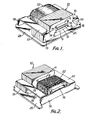
- Figure 1 is a simplified perspective view of one form of transducer according to the invention,
- Figure 2 is another perspective view of the same transducer from the other end, and
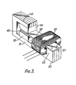
- Figure 3 is a perspective view of the second embodiment.
- In the first example shown in Figures 1 and 2, the transducer comprises a pole piece stack or
assembly 10 formed of a number of parallel flux conductive laminations with rectangular openings 9, assembled together side-by-side to form a central passageway or tunnel.Within this tunnel are located upper or lowerpermanent magnets - Each of the laminations is formed with a projecting
wing 13 on each opposite side and each of the wings has a flatupper face 14 which is accurately positioned to lie coplanar and parallel with a central horizontal plane through the exact centre of the air gap between the magnets (there will be a deliberate small deviation as will be explained below).It is possible that during manufacture the inside corners of the openings 9 and thewing 13 in the laminations may become' radiussed, which could cause small errors in positioning themagnets limbs - The armature of the transducer is generally of E-shape with two lateral
parallel limbs central limb 18 which constitutes the vibrating reed. Thepart 19 of the armature which interconnects the three limbs is bent downwards at 90°, to improve the rigidity and reduce the overall dimensions. The ends of the twofixed limbs flat faces 14 of the wings of the laminations. Thetip 20 of thevibratory limb 18 is positioned between the twomagnets coil 22 which may be mounted on thebase plate 23 of the transducer. The vibratinglimb 18 is connected by a link to a diaphragm (not illustrated) and the coil is connected to an amplifier if used as a microphone or to a supply circuit, if used as a receiver. - The three
limbs central limb tip 20 is required to be equally spaced from the twomagnets face 14 on each pole piece lamination. - It will be noted that each of the
limbs limb 19, but the bending is in the same direction for each limb. Thus, as the bending stresses are relieved in one limb the same occurs in the others and hence the three limbs remain parallel in a common plane thus holding thetip 20 of the vibrating reed central in the air gap. - It will be noted that the pole piece laminations are not bent during manufacture and assembly as occurs in some prior transducers and the
positioning faces 14 are accurately machined or stamped out of the laminations thus providing a positive accurate locating face. Any small inaccuracy in positioning thelimbs 16 on the faces would not seriously affect the positioning of thecentral reed tip 20. - In the second example illustrated in Figure 3, the
pole piece assembly 30 is generally of J-shape and again comprises a stack of flux conducting laminations each having amain limb 31 with ahook portion 32 at one end and ananvil 33 at the other end. A pair ofpermanent magnets hook 32 and themain limb 31, the magnets being polarised in the same direction and spaced apart to form an air gap. The vibrating reed is a simpleflat plate 36 secured rigidly at one end to theupper face 37 of thepole piece anvil 33 and with its other end centralised between the twomagnets coil 38 and attached by a link, not illustrated, to an acoustic diaphragm. - For the reasons given it is important that the moving
end 40 of the reed should be accurately positioned centrally within the air gap. For this purpose the laminations of the pole pieces are so shaped in manufacture that theupper face 37 of the anvil lies coplanar with the under surface of thereed end 40 when it is centralised. Since the reed is a simple flat plate without bends and the pole piece laminations likewise are not bent in manufacture or assembly, there will be no relieving of stresses to introduce inaccuracies,and the assembly and accurate centralising of the reed require no special adjustment procedures. - It will be noted that in both these embodiments each individual lamination of the pole piece provides a complete flux path between the fixed and moving ends of the armature or reed. Also, it will be noted that when the direction of the magnetic flux along the reed alters, in use, the flux continues to pass in either direction through the same junctions between the armature and the pole piece laminations. Thus any difference in the magnetic qualities of the welds or junctions will not affect the operation of the device.
Claims (12)
Priority Applications (3)
| Application Number | Priority Date | Filing Date | Title |
|---|---|---|---|
| AT82302604T ATE22517T1 (en) | 1982-05-21 | 1982-05-21 | ELECTRO-ACOUSTIC TRANSDUCERS. |
| DE8282302604T DE3273417D1 (en) | 1982-05-21 | 1982-05-21 | Electroacoustic transducers |
| EP82302604A EP0094992B1 (en) | 1982-05-21 | 1982-05-21 | Electroacoustic transducers |
Applications Claiming Priority (1)
| Application Number | Priority Date | Filing Date | Title |
|---|---|---|---|
| EP82302604A EP0094992B1 (en) | 1982-05-21 | 1982-05-21 | Electroacoustic transducers |
Publications (2)
| Publication Number | Publication Date |
|---|---|
| EP0094992A1 true EP0094992A1 (en) | 1983-11-30 |
| EP0094992B1 EP0094992B1 (en) | 1986-09-24 |
Family
ID=8189676
Family Applications (1)
| Application Number | Title | Priority Date | Filing Date |
|---|---|---|---|
| EP82302604A Expired EP0094992B1 (en) | 1982-05-21 | 1982-05-21 | Electroacoustic transducers |
Country Status (3)
| Country | Link |
|---|---|
| EP (1) | EP0094992B1 (en) |
| AT (1) | ATE22517T1 (en) |
| DE (1) | DE3273417D1 (en) |
Cited By (4)
| Publication number | Priority date | Publication date | Assignee | Title |
|---|---|---|---|---|
| NL1004669C2 (en) * | 1996-12-02 | 1998-06-03 | Microtronic Nederland Bv | Transducer. |
| US6658134B1 (en) | 1999-08-16 | 2003-12-02 | Sonionmicrotronic Nederland B.V. | Shock improvement for an electroacoustic transducer |
| WO2010025351A3 (en) * | 2008-08-29 | 2010-06-17 | The Penn State Research Foundation | Methods and apparatus for reduced distortion balanced armature devices |
| WO2013090542A1 (en) * | 2011-12-13 | 2013-06-20 | Knowles Electronics, Llc | Apparatus in an acoustic assembly for registering assembly parts |
Citations (5)
| Publication number | Priority date | Publication date | Assignee | Title |
|---|---|---|---|---|
| US2143097A (en) * | 1936-04-10 | 1939-01-10 | Control Instr Co Inc | Telephonic unit |
| DE1158115B (en) * | 1961-10-07 | 1963-11-28 | Sennheiser Electronic | Miniature microphone |
| GB1079045A (en) * | 1963-07-29 | 1967-08-09 | Industrial Res Prod Inc | Electromechanical transducer |
| US3531745A (en) * | 1969-10-22 | 1970-09-29 | Tibbetts Industries | Magnetic translating device with armature flux adjustment means |
| US3935398A (en) * | 1971-07-12 | 1976-01-27 | Industrial Research Products, Inc. | Transducer with improved armature and yoke construction |
-
1982
- 1982-05-21 AT AT82302604T patent/ATE22517T1/en not_active IP Right Cessation
- 1982-05-21 EP EP82302604A patent/EP0094992B1/en not_active Expired
- 1982-05-21 DE DE8282302604T patent/DE3273417D1/en not_active Expired
Patent Citations (5)
| Publication number | Priority date | Publication date | Assignee | Title |
|---|---|---|---|---|
| US2143097A (en) * | 1936-04-10 | 1939-01-10 | Control Instr Co Inc | Telephonic unit |
| DE1158115B (en) * | 1961-10-07 | 1963-11-28 | Sennheiser Electronic | Miniature microphone |
| GB1079045A (en) * | 1963-07-29 | 1967-08-09 | Industrial Res Prod Inc | Electromechanical transducer |
| US3531745A (en) * | 1969-10-22 | 1970-09-29 | Tibbetts Industries | Magnetic translating device with armature flux adjustment means |
| US3935398A (en) * | 1971-07-12 | 1976-01-27 | Industrial Research Products, Inc. | Transducer with improved armature and yoke construction |
Cited By (9)
| Publication number | Priority date | Publication date | Assignee | Title |
|---|---|---|---|---|
| NL1004669C2 (en) * | 1996-12-02 | 1998-06-03 | Microtronic Nederland Bv | Transducer. |
| EP0847226A1 (en) * | 1996-12-02 | 1998-06-10 | Microtronic Nederland B.V. | Transducer, in particular transducer for hearing aids |
| US6658134B1 (en) | 1999-08-16 | 2003-12-02 | Sonionmicrotronic Nederland B.V. | Shock improvement for an electroacoustic transducer |
| WO2010025351A3 (en) * | 2008-08-29 | 2010-06-17 | The Penn State Research Foundation | Methods and apparatus for reduced distortion balanced armature devices |
| US8385583B2 (en) | 2008-08-29 | 2013-02-26 | The Penn State Research Foundation | Methods and apparatus for reduced distortion balanced armature devices |
| WO2013090542A1 (en) * | 2011-12-13 | 2013-06-20 | Knowles Electronics, Llc | Apparatus in an acoustic assembly for registering assembly parts |
| CN104025620A (en) * | 2011-12-13 | 2014-09-03 | 美商楼氏电子有限公司 | Apparatus in an acoustic assembly for registering assembly parts |
| US8837755B2 (en) | 2011-12-13 | 2014-09-16 | Knowles Electronics, Llc | Apparatus in an acoustic assembly for registering assembly parts |
| US9137610B2 (en) | 2011-12-13 | 2015-09-15 | Knowles Electronics, Llc | Apparatus in an acoustic assembly for registering assembly parts |
Also Published As
| Publication number | Publication date |
|---|---|
| DE3273417D1 (en) | 1986-10-30 |
| ATE22517T1 (en) | 1986-10-15 |
| EP0094992B1 (en) | 1986-09-24 |
Similar Documents
| Publication | Publication Date | Title |
|---|---|---|
| US4473722A (en) | Electroacoustic transducers | |
| US3935398A (en) | Transducer with improved armature and yoke construction | |
| JP4084190B2 (en) | Electroacoustic transducer | |
| US4026178A (en) | Magnetic pickup for stringed musical instrument | |
| US7336797B2 (en) | Apparatus and method for generating acoustic energy in a receiver assembly | |
| US11070119B2 (en) | Manufacturing method of vibrating actuator | |
| CN213661928U (en) | Sound production device | |
| CN107222818B (en) | Acoustic-electric conversion device and audio equipment | |
| US3560667A (en) | Transducer having an armature arm split along its length | |
| US3111563A (en) | Electro-mechanical transducer | |
| EP0548579A1 (en) | Balanced armature transducers with transverse gap | |
| US3432622A (en) | Sub-miniature sound transducers | |
| US3177412A (en) | Electro-mechanical transducer | |
| US2412123A (en) | Electromagnetic device | |
| US3531745A (en) | Magnetic translating device with armature flux adjustment means | |
| EP0094992B1 (en) | Electroacoustic transducers | |
| US3460080A (en) | Armature mounting assembly for an electroacoustic transducer | |
| US2891181A (en) | Torque motor | |
| GB2095510A (en) | Electroacoustic transducers | |
| IE53036B1 (en) | Electroacoustic transducers | |
| CN213661929U (en) | Sound production device | |
| US3313892A (en) | Electromechanical transducers | |
| CN213462293U (en) | Sound production device | |
| JPH0560318B2 (en) | ||
| WO2022006887A1 (en) | Linear motor |
Legal Events
| Date | Code | Title | Description |
|---|---|---|---|
| PUAI | Public reference made under article 153(3) epc to a published international application that has entered the european phase |
Free format text: ORIGINAL CODE: 0009012 |
|
| AK | Designated contracting states |
Designated state(s): AT BE CH DE FR GB IT LI LU NL SE |
|
| 17P | Request for examination filed |
Effective date: 19840111 |
|
| GRAA | (expected) grant |
Free format text: ORIGINAL CODE: 0009210 |
|
| AK | Designated contracting states |
Kind code of ref document: B1 Designated state(s): AT BE CH DE FR GB IT LI LU NL SE |
|
| PG25 | Lapsed in a contracting state [announced via postgrant information from national office to epo] |
Ref country code: IT Free format text: LAPSE BECAUSE OF FAILURE TO SUBMIT A TRANSLATION OF THE DESCRIPTION OR TO PAY THE FEE WITHIN THE PRESCRIBED TIME-LIMIT;WARNING: LAPSES OF ITALIAN PATENTS WITH EFFECTIVE DATE BEFORE 2007 MAY HAVE OCCURRED AT ANY TIME BEFORE 2007. THE CORRECT EFFECTIVE DATE MAY BE DIFFERENT FROM THE ONE RECORDED. Effective date: 19860924 Ref country code: AT Effective date: 19860924 |
|
| REF | Corresponds to: |
Ref document number: 22517 Country of ref document: AT Date of ref document: 19861015 Kind code of ref document: T |
|
| PG25 | Lapsed in a contracting state [announced via postgrant information from national office to epo] |
Ref country code: SE Effective date: 19860930 |
|
| REF | Corresponds to: |
Ref document number: 3273417 Country of ref document: DE Date of ref document: 19861030 |
|
| ET | Fr: translation filed | ||
| PG25 | Lapsed in a contracting state [announced via postgrant information from national office to epo] |
Ref country code: LU Free format text: LAPSE BECAUSE OF NON-PAYMENT OF DUE FEES Effective date: 19870531 |
|
| PLBE | No opposition filed within time limit |
Free format text: ORIGINAL CODE: 0009261 |
|
| STAA | Information on the status of an ep patent application or granted ep patent |
Free format text: STATUS: NO OPPOSITION FILED WITHIN TIME LIMIT |
|
| 26N | No opposition filed | ||
| GBPC | Gb: european patent ceased through non-payment of renewal fee | ||
| PG25 | Lapsed in a contracting state [announced via postgrant information from national office to epo] |
Ref country code: GB Free format text: LAPSE BECAUSE OF NON-PAYMENT OF DUE FEES Effective date: 19881122 |
|
| PGFP | Annual fee paid to national office [announced via postgrant information from national office to epo] |
Ref country code: BE Payment date: 20010417 Year of fee payment: 20 |
|
| PGFP | Annual fee paid to national office [announced via postgrant information from national office to epo] |
Ref country code: CH Payment date: 20010525 Year of fee payment: 20 |
|
| PGFP | Annual fee paid to national office [announced via postgrant information from national office to epo] |
Ref country code: FR Payment date: 20010528 Year of fee payment: 20 |
|
| PGFP | Annual fee paid to national office [announced via postgrant information from national office to epo] |
Ref country code: DE Payment date: 20010530 Year of fee payment: 20 |
|
| PGFP | Annual fee paid to national office [announced via postgrant information from national office to epo] |
Ref country code: NL Payment date: 20010531 Year of fee payment: 20 |
|
| BE20 | Be: patent expired |
Free format text: 20020521 *KNOWLES ELECTRONICS CY |
|
| PG25 | Lapsed in a contracting state [announced via postgrant information from national office to epo] |
Ref country code: LI Free format text: LAPSE BECAUSE OF EXPIRATION OF PROTECTION Effective date: 20020520 Ref country code: CH Free format text: LAPSE BECAUSE OF EXPIRATION OF PROTECTION Effective date: 20020520 |
|
| PG25 | Lapsed in a contracting state [announced via postgrant information from national office to epo] |
Ref country code: NL Free format text: LAPSE BECAUSE OF EXPIRATION OF PROTECTION Effective date: 20020521 |
|
| NLS | Nl: assignments of ep-patents |
Owner name: KNOWLES ELECTRONICS, LLC |
|
| NLT1 | Nl: modifications of names registered in virtue of documents presented to the patent office pursuant to art. 16 a, paragraph 1 |
Owner name: KNOWLES EUROPE |
|
| REG | Reference to a national code |
Ref country code: CH Ref legal event code: PL |
|
| NLV7 | Nl: ceased due to reaching the maximum lifetime of a patent |
Effective date: 20020521 |
|
| NLS | Nl: assignments of ep-patents |
Owner name: KNOWLES ELECTRONICS, LLC |
|
| NLT1 | Nl: modifications of names registered in virtue of documents presented to the patent office pursuant to art. 16 a, paragraph 1 |
Owner name: KNOWLES EUROPE |