EP0094829B1 - Endoprosthetic bone joint devices - Google Patents
Endoprosthetic bone joint devices Download PDFInfo
- Publication number
- EP0094829B1 EP0094829B1 EP83302783A EP83302783A EP0094829B1 EP 0094829 B1 EP0094829 B1 EP 0094829B1 EP 83302783 A EP83302783 A EP 83302783A EP 83302783 A EP83302783 A EP 83302783A EP 0094829 B1 EP0094829 B1 EP 0094829B1
- Authority
- EP
- European Patent Office
- Prior art keywords
- elements
- bone
- parts
- passageways
- flange
- Prior art date
- Legal status (The legal status is an assumption and is not a legal conclusion. Google has not performed a legal analysis and makes no representation as to the accuracy of the status listed.)
- Expired
Links
Images

Classifications
-
- A—HUMAN NECESSITIES
- A61—MEDICAL OR VETERINARY SCIENCE; HYGIENE
- A61F—FILTERS IMPLANTABLE INTO BLOOD VESSELS; PROSTHESES; DEVICES PROVIDING PATENCY TO, OR PREVENTING COLLAPSING OF, TUBULAR STRUCTURES OF THE BODY, e.g. STENTS; ORTHOPAEDIC, NURSING OR CONTRACEPTIVE DEVICES; FOMENTATION; TREATMENT OR PROTECTION OF EYES OR EARS; BANDAGES, DRESSINGS OR ABSORBENT PADS; FIRST-AID KITS
- A61F2/00—Filters implantable into blood vessels; Prostheses, i.e. artificial substitutes or replacements for parts of the body; Appliances for connecting them with the body; Devices providing patency to, or preventing collapsing of, tubular structures of the body, e.g. stents
- A61F2/02—Prostheses implantable into the body
- A61F2/30—Joints
- A61F2/32—Joints for the hip
- A61F2/36—Femoral heads ; Femoral endoprostheses
- A61F2/3601—Femoral heads ; Femoral endoprostheses for replacing only the epiphyseal or metaphyseal parts of the femur, e.g. endoprosthetic femoral heads or necks directly fixed to the natural femur by internal fixation devices
-
- A—HUMAN NECESSITIES
- A61—MEDICAL OR VETERINARY SCIENCE; HYGIENE
- A61B—DIAGNOSIS; SURGERY; IDENTIFICATION
- A61B17/00—Surgical instruments, devices or methods, e.g. tourniquets
- A61B17/56—Surgical instruments or methods for treatment of bones or joints; Devices specially adapted therefor
- A61B17/58—Surgical instruments or methods for treatment of bones or joints; Devices specially adapted therefor for osteosynthesis, e.g. bone plates, screws, setting implements or the like
- A61B17/68—Internal fixation devices, including fasteners and spinal fixators, even if a part thereof projects from the skin
- A61B17/84—Fasteners therefor or fasteners being internal fixation devices
- A61B17/842—Flexible wires, bands or straps
-
- A—HUMAN NECESSITIES
- A61—MEDICAL OR VETERINARY SCIENCE; HYGIENE
- A61F—FILTERS IMPLANTABLE INTO BLOOD VESSELS; PROSTHESES; DEVICES PROVIDING PATENCY TO, OR PREVENTING COLLAPSING OF, TUBULAR STRUCTURES OF THE BODY, e.g. STENTS; ORTHOPAEDIC, NURSING OR CONTRACEPTIVE DEVICES; FOMENTATION; TREATMENT OR PROTECTION OF EYES OR EARS; BANDAGES, DRESSINGS OR ABSORBENT PADS; FIRST-AID KITS
- A61F2/00—Filters implantable into blood vessels; Prostheses, i.e. artificial substitutes or replacements for parts of the body; Appliances for connecting them with the body; Devices providing patency to, or preventing collapsing of, tubular structures of the body, e.g. stents
- A61F2/02—Prostheses implantable into the body
- A61F2/30—Joints
- A61F2/3094—Designing or manufacturing processes
- A61F2/30965—Reinforcing the prosthesis by embedding particles or fibres during moulding or dipping
-
- A—HUMAN NECESSITIES
- A61—MEDICAL OR VETERINARY SCIENCE; HYGIENE
- A61F—FILTERS IMPLANTABLE INTO BLOOD VESSELS; PROSTHESES; DEVICES PROVIDING PATENCY TO, OR PREVENTING COLLAPSING OF, TUBULAR STRUCTURES OF THE BODY, e.g. STENTS; ORTHOPAEDIC, NURSING OR CONTRACEPTIVE DEVICES; FOMENTATION; TREATMENT OR PROTECTION OF EYES OR EARS; BANDAGES, DRESSINGS OR ABSORBENT PADS; FIRST-AID KITS
- A61F2/00—Filters implantable into blood vessels; Prostheses, i.e. artificial substitutes or replacements for parts of the body; Appliances for connecting them with the body; Devices providing patency to, or preventing collapsing of, tubular structures of the body, e.g. stents
- A61F2/02—Prostheses implantable into the body
- A61F2/28—Bones
- A61F2002/2817—Bone stimulation by chemical reactions or by osteogenic or biological products for enhancing ossification, e.g. by bone morphogenetic or morphogenic proteins [BMP] or by transforming growth factors [TGF]
-
- A—HUMAN NECESSITIES
- A61—MEDICAL OR VETERINARY SCIENCE; HYGIENE
- A61F—FILTERS IMPLANTABLE INTO BLOOD VESSELS; PROSTHESES; DEVICES PROVIDING PATENCY TO, OR PREVENTING COLLAPSING OF, TUBULAR STRUCTURES OF THE BODY, e.g. STENTS; ORTHOPAEDIC, NURSING OR CONTRACEPTIVE DEVICES; FOMENTATION; TREATMENT OR PROTECTION OF EYES OR EARS; BANDAGES, DRESSINGS OR ABSORBENT PADS; FIRST-AID KITS
- A61F2/00—Filters implantable into blood vessels; Prostheses, i.e. artificial substitutes or replacements for parts of the body; Appliances for connecting them with the body; Devices providing patency to, or preventing collapsing of, tubular structures of the body, e.g. stents
- A61F2/02—Prostheses implantable into the body
- A61F2/28—Bones
- A61F2002/2821—Bone stimulation by electromagnetic fields or electric current for enhancing ossification
-
- A—HUMAN NECESSITIES
- A61—MEDICAL OR VETERINARY SCIENCE; HYGIENE
- A61F—FILTERS IMPLANTABLE INTO BLOOD VESSELS; PROSTHESES; DEVICES PROVIDING PATENCY TO, OR PREVENTING COLLAPSING OF, TUBULAR STRUCTURES OF THE BODY, e.g. STENTS; ORTHOPAEDIC, NURSING OR CONTRACEPTIVE DEVICES; FOMENTATION; TREATMENT OR PROTECTION OF EYES OR EARS; BANDAGES, DRESSINGS OR ABSORBENT PADS; FIRST-AID KITS
- A61F2/00—Filters implantable into blood vessels; Prostheses, i.e. artificial substitutes or replacements for parts of the body; Appliances for connecting them with the body; Devices providing patency to, or preventing collapsing of, tubular structures of the body, e.g. stents
- A61F2/02—Prostheses implantable into the body
- A61F2/30—Joints
- A61F2002/30001—Additional features of subject-matter classified in A61F2/28, A61F2/30 and subgroups thereof
- A61F2002/30108—Shapes
- A61F2002/3011—Cross-sections or two-dimensional shapes
- A61F2002/30112—Rounded shapes, e.g. with rounded corners
- A61F2002/30113—Rounded shapes, e.g. with rounded corners circular
- A61F2002/30118—Rounded shapes, e.g. with rounded corners circular concentric circles
-
- A—HUMAN NECESSITIES
- A61—MEDICAL OR VETERINARY SCIENCE; HYGIENE
- A61F—FILTERS IMPLANTABLE INTO BLOOD VESSELS; PROSTHESES; DEVICES PROVIDING PATENCY TO, OR PREVENTING COLLAPSING OF, TUBULAR STRUCTURES OF THE BODY, e.g. STENTS; ORTHOPAEDIC, NURSING OR CONTRACEPTIVE DEVICES; FOMENTATION; TREATMENT OR PROTECTION OF EYES OR EARS; BANDAGES, DRESSINGS OR ABSORBENT PADS; FIRST-AID KITS
- A61F2/00—Filters implantable into blood vessels; Prostheses, i.e. artificial substitutes or replacements for parts of the body; Appliances for connecting them with the body; Devices providing patency to, or preventing collapsing of, tubular structures of the body, e.g. stents
- A61F2/02—Prostheses implantable into the body
- A61F2/30—Joints
- A61F2002/30001—Additional features of subject-matter classified in A61F2/28, A61F2/30 and subgroups thereof
- A61F2002/30316—The prosthesis having different structural features at different locations within the same prosthesis; Connections between prosthetic parts; Special structural features of bone or joint prostheses not otherwise provided for
- A61F2002/30329—Connections or couplings between prosthetic parts, e.g. between modular parts; Connecting elements
- A61F2002/30331—Connections or couplings between prosthetic parts, e.g. between modular parts; Connecting elements made by longitudinally pushing a protrusion into a complementarily-shaped recess, e.g. held by friction fit
- A61F2002/30332—Conically- or frustoconically-shaped protrusion and recess
-
- A—HUMAN NECESSITIES
- A61—MEDICAL OR VETERINARY SCIENCE; HYGIENE
- A61F—FILTERS IMPLANTABLE INTO BLOOD VESSELS; PROSTHESES; DEVICES PROVIDING PATENCY TO, OR PREVENTING COLLAPSING OF, TUBULAR STRUCTURES OF THE BODY, e.g. STENTS; ORTHOPAEDIC, NURSING OR CONTRACEPTIVE DEVICES; FOMENTATION; TREATMENT OR PROTECTION OF EYES OR EARS; BANDAGES, DRESSINGS OR ABSORBENT PADS; FIRST-AID KITS
- A61F2/00—Filters implantable into blood vessels; Prostheses, i.e. artificial substitutes or replacements for parts of the body; Appliances for connecting them with the body; Devices providing patency to, or preventing collapsing of, tubular structures of the body, e.g. stents
- A61F2/02—Prostheses implantable into the body
- A61F2/30—Joints
- A61F2002/30001—Additional features of subject-matter classified in A61F2/28, A61F2/30 and subgroups thereof
- A61F2002/30316—The prosthesis having different structural features at different locations within the same prosthesis; Connections between prosthetic parts; Special structural features of bone or joint prostheses not otherwise provided for
- A61F2002/30329—Connections or couplings between prosthetic parts, e.g. between modular parts; Connecting elements
- A61F2002/30331—Connections or couplings between prosthetic parts, e.g. between modular parts; Connecting elements made by longitudinally pushing a protrusion into a complementarily-shaped recess, e.g. held by friction fit
- A61F2002/30354—Cylindrically-shaped protrusion and recess, e.g. cylinder of circular basis
-
- A—HUMAN NECESSITIES
- A61—MEDICAL OR VETERINARY SCIENCE; HYGIENE
- A61F—FILTERS IMPLANTABLE INTO BLOOD VESSELS; PROSTHESES; DEVICES PROVIDING PATENCY TO, OR PREVENTING COLLAPSING OF, TUBULAR STRUCTURES OF THE BODY, e.g. STENTS; ORTHOPAEDIC, NURSING OR CONTRACEPTIVE DEVICES; FOMENTATION; TREATMENT OR PROTECTION OF EYES OR EARS; BANDAGES, DRESSINGS OR ABSORBENT PADS; FIRST-AID KITS
- A61F2/00—Filters implantable into blood vessels; Prostheses, i.e. artificial substitutes or replacements for parts of the body; Appliances for connecting them with the body; Devices providing patency to, or preventing collapsing of, tubular structures of the body, e.g. stents
- A61F2/02—Prostheses implantable into the body
- A61F2/30—Joints
- A61F2002/30001—Additional features of subject-matter classified in A61F2/28, A61F2/30 and subgroups thereof
- A61F2002/30316—The prosthesis having different structural features at different locations within the same prosthesis; Connections between prosthetic parts; Special structural features of bone or joint prostheses not otherwise provided for
- A61F2002/30329—Connections or couplings between prosthetic parts, e.g. between modular parts; Connecting elements
- A61F2002/30331—Connections or couplings between prosthetic parts, e.g. between modular parts; Connecting elements made by longitudinally pushing a protrusion into a complementarily-shaped recess, e.g. held by friction fit
- A61F2002/30362—Connections or couplings between prosthetic parts, e.g. between modular parts; Connecting elements made by longitudinally pushing a protrusion into a complementarily-shaped recess, e.g. held by friction fit with possibility of relative movement between the protrusion and the recess
- A61F2002/30364—Rotation about the common longitudinal axis
- A61F2002/30367—Rotation about the common longitudinal axis with additional means for preventing said rotation
-
- A—HUMAN NECESSITIES
- A61—MEDICAL OR VETERINARY SCIENCE; HYGIENE
- A61F—FILTERS IMPLANTABLE INTO BLOOD VESSELS; PROSTHESES; DEVICES PROVIDING PATENCY TO, OR PREVENTING COLLAPSING OF, TUBULAR STRUCTURES OF THE BODY, e.g. STENTS; ORTHOPAEDIC, NURSING OR CONTRACEPTIVE DEVICES; FOMENTATION; TREATMENT OR PROTECTION OF EYES OR EARS; BANDAGES, DRESSINGS OR ABSORBENT PADS; FIRST-AID KITS
- A61F2/00—Filters implantable into blood vessels; Prostheses, i.e. artificial substitutes or replacements for parts of the body; Appliances for connecting them with the body; Devices providing patency to, or preventing collapsing of, tubular structures of the body, e.g. stents
- A61F2/02—Prostheses implantable into the body
- A61F2/30—Joints
- A61F2002/30001—Additional features of subject-matter classified in A61F2/28, A61F2/30 and subgroups thereof
- A61F2002/30316—The prosthesis having different structural features at different locations within the same prosthesis; Connections between prosthetic parts; Special structural features of bone or joint prostheses not otherwise provided for
- A61F2002/30329—Connections or couplings between prosthetic parts, e.g. between modular parts; Connecting elements
- A61F2002/30383—Connections or couplings between prosthetic parts, e.g. between modular parts; Connecting elements made by laterally inserting a protrusion, e.g. a rib into a complementarily-shaped groove
- A61F2002/30403—Longitudinally-oriented cooperating ribs and grooves on mating lateral surfaces of a mainly longitudinal connection
-
- A—HUMAN NECESSITIES
- A61—MEDICAL OR VETERINARY SCIENCE; HYGIENE
- A61F—FILTERS IMPLANTABLE INTO BLOOD VESSELS; PROSTHESES; DEVICES PROVIDING PATENCY TO, OR PREVENTING COLLAPSING OF, TUBULAR STRUCTURES OF THE BODY, e.g. STENTS; ORTHOPAEDIC, NURSING OR CONTRACEPTIVE DEVICES; FOMENTATION; TREATMENT OR PROTECTION OF EYES OR EARS; BANDAGES, DRESSINGS OR ABSORBENT PADS; FIRST-AID KITS
- A61F2/00—Filters implantable into blood vessels; Prostheses, i.e. artificial substitutes or replacements for parts of the body; Appliances for connecting them with the body; Devices providing patency to, or preventing collapsing of, tubular structures of the body, e.g. stents
- A61F2/02—Prostheses implantable into the body
- A61F2/30—Joints
- A61F2002/30001—Additional features of subject-matter classified in A61F2/28, A61F2/30 and subgroups thereof
- A61F2002/30316—The prosthesis having different structural features at different locations within the same prosthesis; Connections between prosthetic parts; Special structural features of bone or joint prostheses not otherwise provided for
- A61F2002/30329—Connections or couplings between prosthetic parts, e.g. between modular parts; Connecting elements
- A61F2002/30433—Connections or couplings between prosthetic parts, e.g. between modular parts; Connecting elements using additional screws, bolts, dowels, rivets or washers e.g. connecting screws
-
- A—HUMAN NECESSITIES
- A61—MEDICAL OR VETERINARY SCIENCE; HYGIENE
- A61F—FILTERS IMPLANTABLE INTO BLOOD VESSELS; PROSTHESES; DEVICES PROVIDING PATENCY TO, OR PREVENTING COLLAPSING OF, TUBULAR STRUCTURES OF THE BODY, e.g. STENTS; ORTHOPAEDIC, NURSING OR CONTRACEPTIVE DEVICES; FOMENTATION; TREATMENT OR PROTECTION OF EYES OR EARS; BANDAGES, DRESSINGS OR ABSORBENT PADS; FIRST-AID KITS
- A61F2/00—Filters implantable into blood vessels; Prostheses, i.e. artificial substitutes or replacements for parts of the body; Appliances for connecting them with the body; Devices providing patency to, or preventing collapsing of, tubular structures of the body, e.g. stents
- A61F2/02—Prostheses implantable into the body
- A61F2/30—Joints
- A61F2002/30001—Additional features of subject-matter classified in A61F2/28, A61F2/30 and subgroups thereof
- A61F2002/30316—The prosthesis having different structural features at different locations within the same prosthesis; Connections between prosthetic parts; Special structural features of bone or joint prostheses not otherwise provided for
- A61F2002/30329—Connections or couplings between prosthetic parts, e.g. between modular parts; Connecting elements
- A61F2002/30462—Connections or couplings between prosthetic parts, e.g. between modular parts; Connecting elements retained or tied with a rope, string, thread, wire or cable
-
- A—HUMAN NECESSITIES
- A61—MEDICAL OR VETERINARY SCIENCE; HYGIENE
- A61F—FILTERS IMPLANTABLE INTO BLOOD VESSELS; PROSTHESES; DEVICES PROVIDING PATENCY TO, OR PREVENTING COLLAPSING OF, TUBULAR STRUCTURES OF THE BODY, e.g. STENTS; ORTHOPAEDIC, NURSING OR CONTRACEPTIVE DEVICES; FOMENTATION; TREATMENT OR PROTECTION OF EYES OR EARS; BANDAGES, DRESSINGS OR ABSORBENT PADS; FIRST-AID KITS
- A61F2/00—Filters implantable into blood vessels; Prostheses, i.e. artificial substitutes or replacements for parts of the body; Appliances for connecting them with the body; Devices providing patency to, or preventing collapsing of, tubular structures of the body, e.g. stents
- A61F2/02—Prostheses implantable into the body
- A61F2/30—Joints
- A61F2002/30001—Additional features of subject-matter classified in A61F2/28, A61F2/30 and subgroups thereof
- A61F2002/30316—The prosthesis having different structural features at different locations within the same prosthesis; Connections between prosthetic parts; Special structural features of bone or joint prostheses not otherwise provided for
- A61F2002/30535—Special structural features of bone or joint prostheses not otherwise provided for
- A61F2002/30604—Special structural features of bone or joint prostheses not otherwise provided for modular
-
- A—HUMAN NECESSITIES
- A61—MEDICAL OR VETERINARY SCIENCE; HYGIENE
- A61F—FILTERS IMPLANTABLE INTO BLOOD VESSELS; PROSTHESES; DEVICES PROVIDING PATENCY TO, OR PREVENTING COLLAPSING OF, TUBULAR STRUCTURES OF THE BODY, e.g. STENTS; ORTHOPAEDIC, NURSING OR CONTRACEPTIVE DEVICES; FOMENTATION; TREATMENT OR PROTECTION OF EYES OR EARS; BANDAGES, DRESSINGS OR ABSORBENT PADS; FIRST-AID KITS
- A61F2/00—Filters implantable into blood vessels; Prostheses, i.e. artificial substitutes or replacements for parts of the body; Appliances for connecting them with the body; Devices providing patency to, or preventing collapsing of, tubular structures of the body, e.g. stents
- A61F2/02—Prostheses implantable into the body
- A61F2/30—Joints
- A61F2/30767—Special external or bone-contacting surface, e.g. coating for improving bone ingrowth
- A61F2/30771—Special external or bone-contacting surface, e.g. coating for improving bone ingrowth applied in original prostheses, e.g. holes or grooves
- A61F2002/30772—Apertures or holes, e.g. of circular cross section
- A61F2002/3079—Stepped or enlarged apertures, e.g. having discrete diameter changes
-
- A—HUMAN NECESSITIES
- A61—MEDICAL OR VETERINARY SCIENCE; HYGIENE
- A61F—FILTERS IMPLANTABLE INTO BLOOD VESSELS; PROSTHESES; DEVICES PROVIDING PATENCY TO, OR PREVENTING COLLAPSING OF, TUBULAR STRUCTURES OF THE BODY, e.g. STENTS; ORTHOPAEDIC, NURSING OR CONTRACEPTIVE DEVICES; FOMENTATION; TREATMENT OR PROTECTION OF EYES OR EARS; BANDAGES, DRESSINGS OR ABSORBENT PADS; FIRST-AID KITS
- A61F2/00—Filters implantable into blood vessels; Prostheses, i.e. artificial substitutes or replacements for parts of the body; Appliances for connecting them with the body; Devices providing patency to, or preventing collapsing of, tubular structures of the body, e.g. stents
- A61F2/02—Prostheses implantable into the body
- A61F2/30—Joints
- A61F2/30767—Special external or bone-contacting surface, e.g. coating for improving bone ingrowth
- A61F2/30771—Special external or bone-contacting surface, e.g. coating for improving bone ingrowth applied in original prostheses, e.g. holes or grooves
- A61F2002/30878—Special external or bone-contacting surface, e.g. coating for improving bone ingrowth applied in original prostheses, e.g. holes or grooves with non-sharp protrusions, for instance contacting the bone for anchoring, e.g. keels, pegs, pins, posts, shanks, stems, struts
- A61F2002/30886—Special external or bone-contacting surface, e.g. coating for improving bone ingrowth applied in original prostheses, e.g. holes or grooves with non-sharp protrusions, for instance contacting the bone for anchoring, e.g. keels, pegs, pins, posts, shanks, stems, struts externally-threaded
-
- A—HUMAN NECESSITIES
- A61—MEDICAL OR VETERINARY SCIENCE; HYGIENE
- A61F—FILTERS IMPLANTABLE INTO BLOOD VESSELS; PROSTHESES; DEVICES PROVIDING PATENCY TO, OR PREVENTING COLLAPSING OF, TUBULAR STRUCTURES OF THE BODY, e.g. STENTS; ORTHOPAEDIC, NURSING OR CONTRACEPTIVE DEVICES; FOMENTATION; TREATMENT OR PROTECTION OF EYES OR EARS; BANDAGES, DRESSINGS OR ABSORBENT PADS; FIRST-AID KITS
- A61F2/00—Filters implantable into blood vessels; Prostheses, i.e. artificial substitutes or replacements for parts of the body; Appliances for connecting them with the body; Devices providing patency to, or preventing collapsing of, tubular structures of the body, e.g. stents
- A61F2/02—Prostheses implantable into the body
- A61F2/30—Joints
- A61F2/32—Joints for the hip
- A61F2/36—Femoral heads ; Femoral endoprostheses
- A61F2/3609—Femoral heads or necks; Connections of endoprosthetic heads or necks to endoprosthetic femoral shafts
- A61F2002/3611—Heads or epiphyseal parts of femur
-
- A—HUMAN NECESSITIES
- A61—MEDICAL OR VETERINARY SCIENCE; HYGIENE
- A61F—FILTERS IMPLANTABLE INTO BLOOD VESSELS; PROSTHESES; DEVICES PROVIDING PATENCY TO, OR PREVENTING COLLAPSING OF, TUBULAR STRUCTURES OF THE BODY, e.g. STENTS; ORTHOPAEDIC, NURSING OR CONTRACEPTIVE DEVICES; FOMENTATION; TREATMENT OR PROTECTION OF EYES OR EARS; BANDAGES, DRESSINGS OR ABSORBENT PADS; FIRST-AID KITS
- A61F2/00—Filters implantable into blood vessels; Prostheses, i.e. artificial substitutes or replacements for parts of the body; Appliances for connecting them with the body; Devices providing patency to, or preventing collapsing of, tubular structures of the body, e.g. stents
- A61F2/02—Prostheses implantable into the body
- A61F2/30—Joints
- A61F2/32—Joints for the hip
- A61F2/36—Femoral heads ; Femoral endoprostheses
- A61F2/3609—Femoral heads or necks; Connections of endoprosthetic heads or necks to endoprosthetic femoral shafts
- A61F2002/3625—Necks
- A61F2002/3647—Necks pierced with a longitudinal bore
-
- A—HUMAN NECESSITIES
- A61—MEDICAL OR VETERINARY SCIENCE; HYGIENE
- A61F—FILTERS IMPLANTABLE INTO BLOOD VESSELS; PROSTHESES; DEVICES PROVIDING PATENCY TO, OR PREVENTING COLLAPSING OF, TUBULAR STRUCTURES OF THE BODY, e.g. STENTS; ORTHOPAEDIC, NURSING OR CONTRACEPTIVE DEVICES; FOMENTATION; TREATMENT OR PROTECTION OF EYES OR EARS; BANDAGES, DRESSINGS OR ABSORBENT PADS; FIRST-AID KITS
- A61F2/00—Filters implantable into blood vessels; Prostheses, i.e. artificial substitutes or replacements for parts of the body; Appliances for connecting them with the body; Devices providing patency to, or preventing collapsing of, tubular structures of the body, e.g. stents
- A61F2/02—Prostheses implantable into the body
- A61F2/30—Joints
- A61F2/32—Joints for the hip
- A61F2/36—Femoral heads ; Femoral endoprostheses
- A61F2/3609—Femoral heads or necks; Connections of endoprosthetic heads or necks to endoprosthetic femoral shafts
- A61F2002/365—Connections of heads to necks
-
- A—HUMAN NECESSITIES
- A61—MEDICAL OR VETERINARY SCIENCE; HYGIENE
- A61F—FILTERS IMPLANTABLE INTO BLOOD VESSELS; PROSTHESES; DEVICES PROVIDING PATENCY TO, OR PREVENTING COLLAPSING OF, TUBULAR STRUCTURES OF THE BODY, e.g. STENTS; ORTHOPAEDIC, NURSING OR CONTRACEPTIVE DEVICES; FOMENTATION; TREATMENT OR PROTECTION OF EYES OR EARS; BANDAGES, DRESSINGS OR ABSORBENT PADS; FIRST-AID KITS
- A61F2220/00—Fixations or connections for prostheses classified in groups A61F2/00 - A61F2/26 or A61F2/82 or A61F9/00 or A61F11/00 or subgroups thereof
- A61F2220/0025—Connections or couplings between prosthetic parts, e.g. between modular parts; Connecting elements
- A61F2220/0033—Connections or couplings between prosthetic parts, e.g. between modular parts; Connecting elements made by longitudinally pushing a protrusion into a complementary-shaped recess, e.g. held by friction fit
-
- A—HUMAN NECESSITIES
- A61—MEDICAL OR VETERINARY SCIENCE; HYGIENE
- A61F—FILTERS IMPLANTABLE INTO BLOOD VESSELS; PROSTHESES; DEVICES PROVIDING PATENCY TO, OR PREVENTING COLLAPSING OF, TUBULAR STRUCTURES OF THE BODY, e.g. STENTS; ORTHOPAEDIC, NURSING OR CONTRACEPTIVE DEVICES; FOMENTATION; TREATMENT OR PROTECTION OF EYES OR EARS; BANDAGES, DRESSINGS OR ABSORBENT PADS; FIRST-AID KITS
- A61F2220/00—Fixations or connections for prostheses classified in groups A61F2/00 - A61F2/26 or A61F2/82 or A61F9/00 or A61F11/00 or subgroups thereof
- A61F2220/0025—Connections or couplings between prosthetic parts, e.g. between modular parts; Connecting elements
- A61F2220/0041—Connections or couplings between prosthetic parts, e.g. between modular parts; Connecting elements using additional screws, bolts, dowels or rivets, e.g. connecting screws
-
- A—HUMAN NECESSITIES
- A61—MEDICAL OR VETERINARY SCIENCE; HYGIENE
- A61F—FILTERS IMPLANTABLE INTO BLOOD VESSELS; PROSTHESES; DEVICES PROVIDING PATENCY TO, OR PREVENTING COLLAPSING OF, TUBULAR STRUCTURES OF THE BODY, e.g. STENTS; ORTHOPAEDIC, NURSING OR CONTRACEPTIVE DEVICES; FOMENTATION; TREATMENT OR PROTECTION OF EYES OR EARS; BANDAGES, DRESSINGS OR ABSORBENT PADS; FIRST-AID KITS
- A61F2220/00—Fixations or connections for prostheses classified in groups A61F2/00 - A61F2/26 or A61F2/82 or A61F9/00 or A61F11/00 or subgroups thereof
- A61F2220/0025—Connections or couplings between prosthetic parts, e.g. between modular parts; Connecting elements
- A61F2220/0075—Connections or couplings between prosthetic parts, e.g. between modular parts; Connecting elements sutured, ligatured or stitched, retained or tied with a rope, string, thread, wire or cable
-
- A—HUMAN NECESSITIES
- A61—MEDICAL OR VETERINARY SCIENCE; HYGIENE
- A61F—FILTERS IMPLANTABLE INTO BLOOD VESSELS; PROSTHESES; DEVICES PROVIDING PATENCY TO, OR PREVENTING COLLAPSING OF, TUBULAR STRUCTURES OF THE BODY, e.g. STENTS; ORTHOPAEDIC, NURSING OR CONTRACEPTIVE DEVICES; FOMENTATION; TREATMENT OR PROTECTION OF EYES OR EARS; BANDAGES, DRESSINGS OR ABSORBENT PADS; FIRST-AID KITS
- A61F2230/00—Geometry of prostheses classified in groups A61F2/00 - A61F2/26 or A61F2/82 or A61F9/00 or A61F11/00 or subgroups thereof
- A61F2230/0002—Two-dimensional shapes, e.g. cross-sections
- A61F2230/0004—Rounded shapes, e.g. with rounded corners
- A61F2230/0006—Rounded shapes, e.g. with rounded corners circular
-
- A—HUMAN NECESSITIES
- A61—MEDICAL OR VETERINARY SCIENCE; HYGIENE
- A61F—FILTERS IMPLANTABLE INTO BLOOD VESSELS; PROSTHESES; DEVICES PROVIDING PATENCY TO, OR PREVENTING COLLAPSING OF, TUBULAR STRUCTURES OF THE BODY, e.g. STENTS; ORTHOPAEDIC, NURSING OR CONTRACEPTIVE DEVICES; FOMENTATION; TREATMENT OR PROTECTION OF EYES OR EARS; BANDAGES, DRESSINGS OR ABSORBENT PADS; FIRST-AID KITS
- A61F2310/00—Prostheses classified in A61F2/28 or A61F2/30 - A61F2/44 being constructed from or coated with a particular material
- A61F2310/00005—The prosthesis being constructed from a particular material
- A61F2310/00011—Metals or alloys
- A61F2310/00029—Cobalt-based alloys, e.g. Co-Cr alloys or Vitallium
-
- A—HUMAN NECESSITIES
- A61—MEDICAL OR VETERINARY SCIENCE; HYGIENE
- A61F—FILTERS IMPLANTABLE INTO BLOOD VESSELS; PROSTHESES; DEVICES PROVIDING PATENCY TO, OR PREVENTING COLLAPSING OF, TUBULAR STRUCTURES OF THE BODY, e.g. STENTS; ORTHOPAEDIC, NURSING OR CONTRACEPTIVE DEVICES; FOMENTATION; TREATMENT OR PROTECTION OF EYES OR EARS; BANDAGES, DRESSINGS OR ABSORBENT PADS; FIRST-AID KITS
- A61F2310/00—Prostheses classified in A61F2/28 or A61F2/30 - A61F2/44 being constructed from or coated with a particular material
- A61F2310/00005—The prosthesis being constructed from a particular material
- A61F2310/00179—Ceramics or ceramic-like structures
Definitions
- This invention concerns endoprosthetic bone joint devices and relates more particularly to the securement of such devices to bone, especially, but not exclusively, to one end of a long bone.
- Various techniques for such securement have been proposed but those currently established in routine usage commonly involve the penetration into cancellous bone by elongate rigid members of significant size relative to the bone and as a proportion of the overall device.
- an elongate member is located as a clearance fit in a pre-prepared site and is secured by the use of a gap-filling medium such as an acrylic cement. While generally satisfactory in many instances, this technique can be problematical if any movement occurs at either of the two interfaces which exist between the gap-filling medium on the one hand and the member and the bone on the other hand. Moreover, such movement can occur as a natural consequence of the differing properties which in practice inevitably occur between the materials of the member, the medium and the bone, particularly as bone is a living material having properties which vary in an individual patient and from one to another.
- This technique has been improved in recent years by an emphasis on site preparation involving very thorough cleansing followed by pressurised application of the gap-filling medium to enhance the penetration thereof into the bone, but difficulty can still occur.
- Another technique seeks to effect improvement by the use of a member having a porous coating or equivalent formation which affords securement not by way of a gap-filling medium but instead by the inward growth of natural fibrous material which ossifies within the member.
- This can be viewed as problematical by virtue of the inevitable initial period of significant length during which the device is relatively insecure and the patient must be at least partially immobilised.
- longer term difficulty can arise by resorption of ossified in-grown material as a result of differential properties between this material and that of the member.
- a member is secured by a tapered interference fit in the bone.
- a difficulty in this case is that either the fit is localised over only a part of the member such that movement can develop due to the forces acting on the device during subsequent use, or the fit is sufficiently extensive that the initial penetration involves a risk of undue damage to the bone. Again, differential material properties can cause difficulty.
- An object of the present invention is to provide a further technique, and devices therefor, whereby the various difficulties discussed above are reduced.
- the invention centres in general terms on the provision of a multiplicity of filamentary elements to be driven through part of the device into bone.
- these elements will not possess, individually or collectively, the relative bulk of the prior penetrating elongate members and this contributes to a reduction in any potentially disadvantageous consequences which can otherwise arise from differential material properties or loss of bone as discussed above.
- the elements can penetrate the bone to a significantly greater extent than the prior relatively shallow relieved structures and so afford a more secure anchorage against the effects of the forces which occur in subsequent use of the device.
- this last anchorage can be enhanced by penetration of the elements in a variety of directions to suit an individual situation, whereas the penetration geometry is largely predetermined with the prior devices.
- the elements are intended to penetrate the cancellous material of the bone, including the trabecular structure of the medulla.
- the elements must have sufficient rigidity and other appropriate mechanical properties for this purpose so as to be substantially incompressible relative to the bone material, but the elements will normally exhibit some transverse flexibility to allow bending. Such bending can act to facilitate introduction of the elements, and mutual splaying of the elements resulting from bending will enhance the overall anchorage. Also, a bending capability can potentially accommodate changes in the surrounding bone structure which a bulky rigid material cannot.
- the elements are preferably made of a material having an elastic modulus generally similar to that for bone.
- the elements are intended to be in direct contact with the bone material without the intervention of gap-filling medium, but the individual contribution of any one element to the overall resultant anchorage can be enhanced in various ways.
- the elements can be roughened, barbed or otherwise formed to act mechanically against subsequent movement relative to the bone.
- the elements can be treated or formed to induce or accommodate growth of bone into intimate contact therewith.
- the elements are employed covered with or incorporate material such as hydroxyapatite beneficial to bone growth as a substrate, nutrient or protection.
- the elements are covered with or incorporate a material having negative electrochemical potential with respect to other parts of the device to induce natural growth towards the elements.
- the elements can be provided with a uniform length equating with the maximum likely to be needed, with this length being shortened selectively by the surgeon as required in individual situations.
- a range of lengths can be supplied by the manufacturer.
- the part of the device to be located against the bone which the elements penetrate should have a flanged formation projecting therefrom to engage a corresponding slot formation cut in the bone, these formations being multi-directional. More particularly, it is further preferred at present that this formation on the device should comprise flange portions radiating from the central region of the bone-engaging part towards the periphery thereof to transfer shear force loads towards the bone cortex, which last can suitably be embraced by a peripheral annular flange portion.
- the embodiment of the drawings is a femoral component for use in the hip joint as a hemi- arthroplasty in replacement of the natural femoral head, or in that joint as part of a total arthroplasty additionally involving an acetabular component replacing the associated natural pelvic socket in which the head articulates.
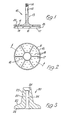
- the component part in Figure 1 is denoted 10 and comprises a plate 11 of disc form having a shaft 12 projecting coaxially from one side thereof.
- This shaft is formed with a key, spline or similar anti-rotation formation at 13 towards its base and is also externally threaded at 14towards its free end.
- the plate On its other side the plate has a flange formation projecting axially therefrom, this formation including a peripherally and concentrically located outer annular skirt 15, a centrally and concentrically located inner annular skirt 16, and a plurality of radially interconnecting webs 17.
- the part 10 has a plurality of apertures 18 passing axially therethrough between the skirts and webs, each such aperture opening into a hemispherically countersunk recess 19 in the one side of the plate.
- the component part of Figure 3 is denoted 20 and comprises an annular body 21 which converges over its length, which length corresponds to that of shaft 12, through a curved portion 22 at the wider end to a terminal conical taper 23 at the narrow end.
- the wider end of the body is of corresponding shape to plate 11 and has a plurality of hemispherical recesses 24 corresponding in diameter and distribution to recesses 19.
- the central passageway of the body is formed with a keyway, spline or other formation at 25 towards the wider end in complementary manner to that at 13 on the shaft 12 to engage non-rotatably thereon with the recesses 19 and 24 superimposed, and the passageway is counterbored at 26 at the narrow end of the body.
- Figure 4 illustrates remaining parts of the component.
- the parts in question comprise a nut 30 to engage the thread 14 of shaft 12 and seat in the counterbore 26 of body 21, a ball 40 having a conically tapered bore 41 partway therethrough to engage the taper 23 of body 21, and a plurality of filamentary elements 50 sized to pass through apertures 18 and having spherical enlargements 51 at one end complementary with recesses 19 and 24.
- FIG. 4 Use of the component is also shown by Figure 4.
- the femoral head of a femur indicated in partial outline at 60 is excised through the neck to receive component part 10 thereover.
- the flange formation of this part engages the bone, complementary slots having been cut in the latter to receive the webs 17 and the inner skirt impacting into the upper end of the medulla.
- the filamentary elements 50 are then driven through respective apertures 18 into the cancellous bone, the terminal enlargements 51 seating in the recesses 19.
- the elements are driven in varying directions, suitably to follow the general trabecular pattern in the bone, the elements being selectively sized to avoid emergence through the bone cortex.
- the filamentary elements can number between five and thirty, and suitably vary between 3 and 15 cm in length and 0.25 and 2.0 mm in diameter.
- the elements are suitably of surface sintered high tensile titanium wire with titanium heads welded thereon
- the component parts 10 and 20 are suitably of a cast chromium- cobalt alloy
- the nut can be of similar metal to the last parts butwith a polyethylene linear to lock the same
- the ball is suitably of a ceramic.
- the materials suitable for use with the invention can vary from those indicated for the embodiment and can include other metals, and synthetic and composite materials.
- Carbon composite material such as carbon-reinforced carbon fibre form, is thought particularly suitable for the penetrating elements because the elastic modulus can be similar to that for bone and a selected porosity can be provided.
- the number and distribution of the penetrating elements can of course be varied to suit individual circumstances. However, it is thought appropriate to concentrate these elements medially and laterally in relation to the femur, these locations being, according to current thinking and understanding, the main load bearing regions within the femur. Moreover, because these regions are considered to be respectively subject to compressive and tensile load forces, the elements may be correspondingly of different forms to better take account of these forces.
- the shape of the disc form plate can vary between circular and substantially elliptical to suit the direction of the cut made to excise the femoral head.
- the femoral neck has a cross-sectional shape which progresses from circular just below the head to elliptical towards the greater trochanter.
- a further alternative which may well be found to be preferable is to form the distal surface of the plate, i.e. that surface which is in a position with the cut surface of the femoral head, as part of a sphere such that all points of contact between plate surface and bone are equidistant from the centre of the prosthetic femoral head. Furthermore the radius of the sphere will be equal to the distance between the centre of the prosthetic head and the plate to bone interface.
- peripheral skirt members for the proposed femoral component, such members being intended to clip in place. These members will serve to provide a smooth surface to abut with adjacent muscles and other parts of the natural capsule of the hip joint, and offer a choice of depth to suit the requirements of individual patients in this respect.
- the radial flanges can be extended to penetrate the bone further and, in fact, act as the main anchorage for the component.
- the flanges are, as noted for the filamentary elements, preferably matched to bone in respect of elastic modulus, and additionally formed to promote in-growth. Indeed, these last features can be suitably increased in effect towards the free ends of the flanges.
- a simplified form of the illustrated embodiment has been made without flanges and secured to the femoral neck of a glycerine embalmed femur with 12 filaments each no longer than 4 cm.
- This mock-up was tested on an Instron or other compression loading machine at loads of up to 454 kg (1000 Ib) without evident deformation either visually or as judged by comparison of pre- and post-stress X-rays.
Description
- This invention concerns endoprosthetic bone joint devices and relates more particularly to the securement of such devices to bone, especially, but not exclusively, to one end of a long bone. Various techniques for such securement have been proposed but those currently established in routine usage commonly involve the penetration into cancellous bone by elongate rigid members of significant size relative to the bone and as a proportion of the overall device.
- In the most common of these techniques an elongate member is located as a clearance fit in a pre-prepared site and is secured by the use of a gap-filling medium such as an acrylic cement. While generally satisfactory in many instances, this technique can be problematical if any movement occurs at either of the two interfaces which exist between the gap-filling medium on the one hand and the member and the bone on the other hand. Moreover, such movement can occur as a natural consequence of the differing properties which in practice inevitably occur between the materials of the member, the medium and the bone, particularly as bone is a living material having properties which vary in an individual patient and from one to another. This technique has been improved in recent years by an emphasis on site preparation involving very thorough cleansing followed by pressurised application of the gap-filling medium to enhance the penetration thereof into the bone, but difficulty can still occur.
- Another technique seeks to effect improvement by the use of a member having a porous coating or equivalent formation which affords securement not by way of a gap-filling medium but instead by the inward growth of natural fibrous material which ossifies within the member. This can be viewed as problematical by virtue of the inevitable initial period of significant length during which the device is relatively insecure and the patient must be at least partially immobilised. Moreover, longer term difficulty can arise by resorption of ossified in-grown material as a result of differential properties between this material and that of the member.
- In yet another technique a member is secured by a tapered interference fit in the bone. A difficulty in this case is that either the fit is localised over only a part of the member such that movement can develop due to the forces acting on the device during subsequent use, or the fit is sufficiently extensive that the initial penetration involves a risk of undue damage to the bone. Again, differential material properties can cause difficulty.
- It should be understood that these comments on particular techniques for securement to bone are by no means exhaustive but are intended to provide a brief and somewhat generalised appreciation of the difficulties of a complex situation. However, it will be evident that a common cause of difficulty arises from the largely inevitable use of materials having different properties from bone, and such a difficulty is heightened in its consequences by use of those materials for penetration in relatively bulky form. Moreover, such penetration can be problematical in other ways. For example, the very nature of the penetration is such that any introduced infection will be deeply sited. Also, such penetration can require the removal of a significant volume of bone during site preparation and this is doubly disadvantageous in the consequent reduction of blood flow and in compromising the availability of remedial measures if the associated device is not successful.
- It is also known from DE-B-1164019 to use several elongate pins in place of the single elongate member to secure the femoral portion of a hip joint prosthesis to the femur.
- It should be mentioned for completeness in this general context that a securement technique does exist in which the above difficulties are notably less evident, but the technique is only commonly applicable to particular situations. The technique in question involves the use of relatively shallow devices having a relieved surface configuration, but no elongate members, for cooperation with a gap-filling medium in a naturally concave site such as the acetabulum of the hip joint. The same technique has been applied to form an effective capping for the femoral head at the hip, but this appears not have been sufficiently successful to have induced a widespread routine usage due, at least in part, to inadequacy of the resultant anchorage in surviving the forces which act thereon during subsequent usage of the device.
- An object of the present invention is to provide a further technique, and devices therefor, whereby the various difficulties discussed above are reduced. To this end the invention centres in general terms on the provision of a multiplicity of filamentary elements to be driven through part of the device into bone.
- Clearly, these elements will not possess, individually or collectively, the relative bulk of the prior penetrating elongate members and this contributes to a reduction in any potentially disadvantageous consequences which can otherwise arise from differential material properties or loss of bone as discussed above. At the same time the elements can penetrate the bone to a significantly greater extent than the prior relatively shallow relieved structures and so afford a more secure anchorage against the effects of the forces which occur in subsequent use of the device. Moreover, this last anchorage can be enhanced by penetration of the elements in a variety of directions to suit an individual situation, whereas the penetration geometry is largely predetermined with the prior devices.
- The elements are intended to penetrate the cancellous material of the bone, including the trabecular structure of the medulla. The elements must have sufficient rigidity and other appropriate mechanical properties for this purpose so as to be substantially incompressible relative to the bone material, but the elements will normally exhibit some transverse flexibility to allow bending. Such bending can act to facilitate introduction of the elements, and mutual splaying of the elements resulting from bending will enhance the overall anchorage. Also, a bending capability can potentially accommodate changes in the surrounding bone structure which a bulky rigid material cannot. In this last connection also, the elements are preferably made of a material having an elastic modulus generally similar to that for bone.
- The elements are intended to be in direct contact with the bone material without the intervention of gap-filling medium, but the individual contribution of any one element to the overall resultant anchorage can be enhanced in various ways. For example, the elements can be roughened, barbed or otherwise formed to act mechanically against subsequent movement relative to the bone. Also, the elements can be treated or formed to induce or accommodate growth of bone into intimate contact therewith. In one form of the invention for this purpose, the elements are employed covered with or incorporate material such as hydroxyapatite beneficial to bone growth as a substrate, nutrient or protection. In another such form of the invention, the elements are covered with or incorporate a material having negative electrochemical potential with respect to other parts of the device to induce natural growth towards the elements. These two forms of the invention can be combined if the added material gives rise to cathodic dissolution products beneficial to bone growth, or if the cathodic dissolution progressively releases, or exposes for release, additional material incorporated therewith.
- In practice the elements can be provided with a uniform length equating with the maximum likely to be needed, with this length being shortened selectively by the surgeon as required in individual situations. Alternatively, a range of lengths can be supplied by the manufacturer.
- Also in practice it is appropriate to provide the elements with enlargements at one end for captive locking under compression between two parts of the related device with the free ends of the elements penetrating the bone.
- Another preferred feature of the invention is that the part of the device to be located against the bone which the elements penetrate should have a flanged formation projecting therefrom to engage a corresponding slot formation cut in the bone, these formations being multi-directional. More particularly, it is further preferred at present that this formation on the device should comprise flange portions radiating from the central region of the bone-engaging part towards the periphery thereof to transfer shear force loads towards the bone cortex, which last can suitably be embraced by a peripheral annular flange portion.
- The invention as so far described is clarified, by way of example, with reference to one embodiment thereof illustrated in the accompanying drawings in which:-
- Figures 1 and 2 respectively illustrate one part of the embodiment in partially sectioned side view and inverted plan view,
- Figure 3 illustrates in cross-sectional view another such part, and
- Figure 4 illustrates these two parts in use with other parts and the associated filamentary elements.
- The embodiment of the drawings is a femoral component for use in the hip joint as a hemi- arthroplasty in replacement of the natural femoral head, or in that joint as part of a total arthroplasty additionally involving an acetabular component replacing the associated natural pelvic socket in which the head articulates.
- The component part in Figure 1 is denoted 10 and comprises a
plate 11 of disc form having ashaft 12 projecting coaxially from one side thereof. This shaft is formed with a key, spline or similar anti-rotation formation at 13 towards its base and is also externally threaded at 14towards its free end. - On its other side the plate has a flange formation projecting axially therefrom, this formation including a peripherally and concentrically located outer
annular skirt 15, a centrally and concentrically located innerannular skirt 16, and a plurality of radially interconnectingwebs 17. - Lastly, the
part 10 has a plurality ofapertures 18 passing axially therethrough between the skirts and webs, each such aperture opening into a hemispherically countersunk recess 19 in the one side of the plate. - The component part of Figure 3 is denoted 20 and comprises an
annular body 21 which converges over its length, which length corresponds to that ofshaft 12, through acurved portion 22 at the wider end to a terminalconical taper 23 at the narrow end. - The wider end of the body is of corresponding shape to
plate 11 and has a plurality ofhemispherical recesses 24 corresponding in diameter and distribution to recesses 19. The central passageway of the body is formed with a keyway, spline or other formation at 25 towards the wider end in complementary manner to that at 13 on theshaft 12 to engage non-rotatably thereon with therecesses 19 and 24 superimposed, and the passageway is counterbored at 26 at the narrow end of the body. - Figure 4 illustrates remaining parts of the component. The parts in question comprise a
nut 30 to engage the thread 14 ofshaft 12 and seat in thecounterbore 26 ofbody 21, aball 40 having a conicallytapered bore 41 partway therethrough to engage thetaper 23 ofbody 21, and a plurality offilamentary elements 50 sized to pass throughapertures 18 and havingspherical enlargements 51 at one end complementary withrecesses 19 and 24. - Use of the component is also shown by Figure 4. The femoral head of a femur indicated in partial outline at 60 is excised through the neck to receive
component part 10 thereover. The flange formation of this part engages the bone, complementary slots having been cut in the latter to receive thewebs 17 and the inner skirt impacting into the upper end of the medulla. - The
filamentary elements 50 are then driven throughrespective apertures 18 into the cancellous bone, theterminal enlargements 51 seating in the recesses 19. The elements are driven in varying directions, suitably to follow the general trabecular pattern in the bone, the elements being selectively sized to avoid emergence through the bone cortex. - Thereafter the
component part 20 is engaged over and keyed with thepart 10 to seat itsrecesses 24 over theenlargements 51, this subassembly is secured by thenut 30, and theball 40 is engaged on thepart 20 by interference fit between the respective mutuallycomplementary tapers - The filamentary elements can number between five and thirty, and suitably vary between 3 and 15 cm in length and 0.25 and 2.0 mm in diameter. Regarding materials: the elements are suitably of surface sintered high tensile titanium wire with titanium heads welded thereon, the
component parts - While the invention has just been described with more particular reference to the illustrated embodiment, it is variable in different ways. Application is, of course, not confined to a femoral component. However this example is apt insofar as such components are the longest established and still most widely used in routine orthopaedic practice involving an endoprosthesis. In addition femoral components in common current usage typify the difficulties first discussed above.
- Also, the materials suitable for use with the invention can vary from those indicated for the embodiment and can include other metals, and synthetic and composite materials. Carbon composite material, such as carbon-reinforced carbon fibre form, is thought particularly suitable for the penetrating elements because the elastic modulus can be similar to that for bone and a selected porosity can be provided.
- The number and distribution of the penetrating elements can of course be varied to suit individual circumstances. However, it is thought appropriate to concentrate these elements medially and laterally in relation to the femur, these locations being, according to current thinking and understanding, the main load bearing regions within the femur. Moreover, because these regions are considered to be respectively subject to compressive and tensile load forces, the elements may be correspondingly of different forms to better take account of these forces.
- The shape of the disc form plate can vary between circular and substantially elliptical to suit the direction of the cut made to excise the femoral head. In nature, apart from differences in overall bone size, the femoral neck has a cross-sectional shape which progresses from circular just below the head to elliptical towards the greater trochanter. Thus provision of a range of shapes as above will be appropriate to suit variation of cut direction by the surgeon and some of this range can be associated with a shaft which is slightly inclined from an axial disposition to allow for a slightly oblique cut. However, it is expected that further development of the invention will determine optimum excision geometry whereby a requirement for undue variation in component geometry is avoided.
- A further alternative which may well be found to be preferable is to form the distal surface of the plate, i.e. that surface which is in a position with the cut surface of the femoral head, as part of a sphere such that all points of contact between plate surface and bone are equidistant from the centre of the prosthetic femoral head. Furthermore the radius of the sphere will be equal to the distance between the centre of the prosthetic head and the plate to bone interface. By this configuration it is predicted that with the exception of frictional forces arising from the interface between the prosthetic femoral head and the acetabular component, all forces passing through the femoral neck will pass through the plate to bone interface perpendicular to the interface thus minimising or avoiding shear forces on this interface.
- It may also be advantageous to provide a range of separate peripheral skirt members for the proposed femoral component, such members being intended to clip in place. These members will serve to provide a smooth surface to abut with adjacent muscles and other parts of the natural capsule of the hip joint, and offer a choice of depth to suit the requirements of individual patients in this respect.
- In yet another variation, the radial flanges can be extended to penetrate the bone further and, in fact, act as the main anchorage for the component. In this case the flanges are, as noted for the filamentary elements, preferably matched to bone in respect of elastic modulus, and additionally formed to promote in-growth. Indeed, these last features can be suitably increased in effect towards the free ends of the flanges.
- Lastly, as an indication of the powers of securement afforded by the presently proposed technique: a simplified form of the illustrated embodiment has been made without flanges and secured to the femoral neck of a glycerine embalmed femur with 12 filaments each no longer than 4 cm. This mock-up was tested on an Instron or other compression loading machine at loads of up to 454 kg (1000 Ib) without evident deformation either visually or as judged by comparison of pre- and post-stress X-rays.
Claims (16)
Applications Claiming Priority (2)
| Application Number | Priority Date | Filing Date | Title |
|---|---|---|---|
| GB8214347 | 1982-05-17 | ||
| GB8214347 | 1982-05-17 |
Publications (3)
| Publication Number | Publication Date |
|---|---|
| EP0094829A2 EP0094829A2 (en) | 1983-11-23 |
| EP0094829A3 EP0094829A3 (en) | 1984-03-28 |
| EP0094829B1 true EP0094829B1 (en) | 1986-01-02 |
Family
ID=10530412
Family Applications (1)
| Application Number | Title | Priority Date | Filing Date |
|---|---|---|---|
| EP83302783A Expired EP0094829B1 (en) | 1982-05-17 | 1983-05-17 | Endoprosthetic bone joint devices |
Country Status (5)
| Country | Link |
|---|---|
| US (1) | US4532660A (en) |
| EP (1) | EP0094829B1 (en) |
| DE (1) | DE3361687D1 (en) |
| GB (1) | GB2120103B (en) |
| IE (1) | IE55242B1 (en) |
Families Citing this family (79)
| Publication number | Priority date | Publication date | Assignee | Title |
|---|---|---|---|---|
| US4659331A (en) * | 1983-11-28 | 1987-04-21 | Regents Of University Of Michigan | Prosthesis interface surface and method of implanting |
| DE3423667A1 (en) * | 1984-05-08 | 1985-11-28 | Rüdiger Dipl.-Ing. 5204 Lohmar Scheunemann | IMPLANT FOR BONE AND TOOTH ROOT REPLACEMENT WITH SPECIAL TRANSITION STRUCTURE BETWEEN BONES AND IMPLANT CORE AND BONE SIDE WHOLE OR PARTLY RESORBABLE MATRIX |
| US4904264A (en) * | 1984-05-08 | 1990-02-27 | Fried. Krupp Gmbh | Artifical joint system |
| GB8419559D0 (en) * | 1984-08-01 | 1984-09-05 | Field R E | Endoprosthetic bone joint components |
| GB8524823D0 (en) * | 1985-10-08 | 1985-11-13 | Finsbury Instr Ltd | Orthopaedic implants |
| DE3774799D1 (en) * | 1986-08-15 | 1992-01-09 | Boehringer Mannheim Corp., Indianapolis, Ind., Us | |
| US5080685A (en) * | 1986-08-15 | 1992-01-14 | Boehringer Mannheim Corporation | Modular hip prosthesis |
| US5314479A (en) * | 1986-08-15 | 1994-05-24 | Depuy Inc. | Modular prosthesis |
| CH676196A5 (en) * | 1988-08-30 | 1990-12-28 | Sulzer Ag | |
| US5342366A (en) * | 1992-02-19 | 1994-08-30 | Biomet, Inc. | Surgical instruments for hip revision |
| DE4215186C1 (en) * | 1992-05-08 | 1994-02-10 | Hartwig Ahnfeldt | Hip prosthesis |
| US5961555A (en) | 1998-03-17 | 1999-10-05 | Huebner; Randall J. | Modular shoulder prosthesis |
| US5549703A (en) * | 1995-02-16 | 1996-08-27 | Smith & Nephew Richards Inc. | Orthopedic prosthesis apparatus with improved taper locking connection |
| US6494913B1 (en) | 1998-03-17 | 2002-12-17 | Acumed, Inc. | Shoulder prosthesis |
| US6168633B1 (en) * | 1998-08-10 | 2001-01-02 | Itzhak Shoher | Composite surface composition for an implant structure |
| NL1009832C2 (en) * | 1998-08-10 | 2000-02-11 | Novarticulate Bv | Hip replacement. |
| US6228123B1 (en) | 1998-08-19 | 2001-05-08 | Depuy Orthopaedics, Inc. | Variable modulus prosthetic hip stem |
| EP1168989B1 (en) * | 1999-04-15 | 2004-09-15 | Franz Sutter | Condyle prosthesis and kit for producing same |
| DE19950406A1 (en) * | 1999-10-20 | 2001-05-31 | Volkmar Jansson | System for covering cartilage defects using cartilage replacement structures |
| GB0007392D0 (en) | 2000-03-27 | 2000-05-17 | Benoist Girard & Cie | Prosthetic femoral component |
| US8114163B2 (en) | 2000-04-10 | 2012-02-14 | Biomet Manufacturing Corp. | Method and apparatus for adjusting height and angle for a radial head |
| US8920509B2 (en) | 2000-04-10 | 2014-12-30 | Biomet Manufacturing, Llc | Modular radial head prosthesis |
| US8535382B2 (en) | 2000-04-10 | 2013-09-17 | Biomet Manufacturing, Llc | Modular radial head prostheses |
| DE60138354D1 (en) * | 2000-11-07 | 2009-05-28 | Erik Leonard Hoffman | Fastening element for an implant, in particular a hip prosthesis |
| NL1016551C2 (en) * | 2000-11-07 | 2002-05-14 | Erik Leonard Hoffman | Fastening element, for hip prosthesis, has plate-shaped supporting element, and hollow pin driven into spongy bone, and secured by fixing plate and openings through which bone can grow |
| US6616697B2 (en) | 2001-03-13 | 2003-09-09 | Nicholas G. Sotereanos | Hip implant assembly |
| US6887243B2 (en) | 2001-03-30 | 2005-05-03 | Triage Medical, Inc. | Method and apparatus for bone fixation with secondary compression |
| US6511481B2 (en) | 2001-03-30 | 2003-01-28 | Triage Medical, Inc. | Method and apparatus for fixation of proximal femoral fractures |
| CN2534997Y (en) * | 2001-09-21 | 2003-02-12 | 钱本文 | Thigh-bone neck protection apparatus |
| DE10158559C2 (en) * | 2001-11-22 | 2003-10-09 | Eska Implants Gmbh & Co | Femoral neck endoprosthesis for an artificial hip joint |
| US7247171B2 (en) * | 2002-03-11 | 2007-07-24 | Sotereanos Nicholas G | Modular hip implants |
| US6793678B2 (en) | 2002-06-27 | 2004-09-21 | Depuy Acromed, Inc. | Prosthetic intervertebral motion disc having dampening |
| EP2100565A1 (en) | 2002-07-19 | 2009-09-16 | Interventional Spine, Inc. | Apparatus for spinal fixation |
| ITUD20020173A1 (en) * | 2002-08-05 | 2004-02-06 | Lima Lto Spa | FEMORAL PROSTHESIS FOR THE HIP JOINT. |
| EP1407728B1 (en) * | 2002-10-07 | 2006-06-14 | Zimmer GmbH | Femoral head prosthesis |
| US20050015148A1 (en) * | 2003-07-18 | 2005-01-20 | Jansen Lex P. | Biocompatible wires and methods of using same to fill bone void |
| US20050203633A1 (en) * | 2004-03-02 | 2005-09-15 | Alfred Fernandes | Lifetime solution for hip dysfunction |
| US7857832B2 (en) | 2004-12-08 | 2010-12-28 | Interventional Spine, Inc. | Method and apparatus for spinal stabilization |
| US7648523B2 (en) * | 2004-12-08 | 2010-01-19 | Interventional Spine, Inc. | Method and apparatus for spinal stabilization |
| US20080004710A1 (en) * | 2006-06-30 | 2008-01-03 | Howmedica Osteonics Corp. | Femoral head resurfacing |
| US20080109085A1 (en) * | 2006-11-03 | 2008-05-08 | Howmedica Osteonics Corp. | Method and apparatus for hip femoral resurfacing tooling |
| US7537618B2 (en) * | 2006-11-13 | 2009-05-26 | Howmedica Osteonics Corp. | Modular humeral head |
| US8579985B2 (en) | 2006-12-07 | 2013-11-12 | Ihip Surgical, Llc | Method and apparatus for hip replacement |
| US8974540B2 (en) | 2006-12-07 | 2015-03-10 | Ihip Surgical, Llc | Method and apparatus for attachment in a modular hip replacement or fracture fixation device |
| WO2008070863A2 (en) | 2006-12-07 | 2008-06-12 | Interventional Spine, Inc. | Intervertebral implant |
| US8029573B2 (en) | 2006-12-07 | 2011-10-04 | Ihip Surgical, Llc | Method and apparatus for total hip replacement |
| US7998176B2 (en) | 2007-06-08 | 2011-08-16 | Interventional Spine, Inc. | Method and apparatus for spinal stabilization |
| US8900307B2 (en) | 2007-06-26 | 2014-12-02 | DePuy Synthes Products, LLC | Highly lordosed fusion cage |
| KR101552476B1 (en) | 2008-01-17 | 2015-09-11 | 신세스 게엠바하 | An expandable intervertebral implant and associated method of manufacturing the same |
| EP2262449B1 (en) | 2008-04-05 | 2020-03-11 | Synthes GmbH | Expandable intervertebral implant |
| US8414584B2 (en) | 2008-07-09 | 2013-04-09 | Icon Orthopaedic Concepts, Llc | Ankle arthrodesis nail and outrigger assembly |
| WO2010006195A1 (en) * | 2008-07-09 | 2010-01-14 | Amei Technologies, Inc. | Ankle arthrodesis nail and outrigger assembly |
| US9526620B2 (en) | 2009-03-30 | 2016-12-27 | DePuy Synthes Products, Inc. | Zero profile spinal fusion cage |
| US9393129B2 (en) | 2009-12-10 | 2016-07-19 | DePuy Synthes Products, Inc. | Bellows-like expandable interbody fusion cage |
| US8979860B2 (en) | 2010-06-24 | 2015-03-17 | DePuy Synthes Products. LLC | Enhanced cage insertion device |
| US9592063B2 (en) | 2010-06-24 | 2017-03-14 | DePuy Synthes Products, Inc. | Universal trial for lateral cages |
| JP5850930B2 (en) | 2010-06-29 | 2016-02-03 | ジンテス ゲゼルシャフト ミット ベシュレンクテル ハフツング | Isolated intervertebral implant |
| US9402732B2 (en) | 2010-10-11 | 2016-08-02 | DePuy Synthes Products, Inc. | Expandable interspinous process spacer implant |
| US9023112B2 (en) | 2011-02-24 | 2015-05-05 | Depuy (Ireland) | Maintaining proper mechanics THA |
| US9668745B2 (en) | 2011-12-19 | 2017-06-06 | Depuy Ireland Unlimited Company | Anatomical concentric spheres THA |
| US8858645B2 (en) | 2012-06-21 | 2014-10-14 | DePuy Synthes Products, LLC | Constrained mobile bearing hip assembly |
| US8940052B2 (en) | 2012-07-26 | 2015-01-27 | DePuy Synthes Products, LLC | Expandable implant |
| US20140067069A1 (en) | 2012-08-30 | 2014-03-06 | Interventional Spine, Inc. | Artificial disc |
| EP2900179A4 (en) * | 2012-09-27 | 2016-12-21 | The General Hospital Corp D/B/A Massachusetts General Hospital | Femoral heads, mobile inserts, acetabular components, and modular junctions for orthopedic implants and methods of using femoral heads, mobile inserts, acetabular components, and modular junctions for orthopedic implants |
| US9522070B2 (en) | 2013-03-07 | 2016-12-20 | Interventional Spine, Inc. | Intervertebral implant |
| US9522028B2 (en) | 2013-07-03 | 2016-12-20 | Interventional Spine, Inc. | Method and apparatus for sacroiliac joint fixation |
| US11426290B2 (en) | 2015-03-06 | 2022-08-30 | DePuy Synthes Products, Inc. | Expandable intervertebral implant, system, kit and method |
| US9913727B2 (en) | 2015-07-02 | 2018-03-13 | Medos International Sarl | Expandable implant |
| US11510788B2 (en) | 2016-06-28 | 2022-11-29 | Eit Emerging Implant Technologies Gmbh | Expandable, angularly adjustable intervertebral cages |
| CN109640889B (en) | 2016-06-28 | 2021-07-30 | Eit 新兴移植技术股份有限公司 | Expandable angularly adjustable intervertebral cage for joint motion |
| US10537436B2 (en) | 2016-11-01 | 2020-01-21 | DePuy Synthes Products, Inc. | Curved expandable cage |
| US10888433B2 (en) | 2016-12-14 | 2021-01-12 | DePuy Synthes Products, Inc. | Intervertebral implant inserter and related methods |
| US10398563B2 (en) | 2017-05-08 | 2019-09-03 | Medos International Sarl | Expandable cage |
| US11344424B2 (en) | 2017-06-14 | 2022-05-31 | Medos International Sarl | Expandable intervertebral implant and related methods |
| US10940016B2 (en) | 2017-07-05 | 2021-03-09 | Medos International Sarl | Expandable intervertebral fusion cage |
| US11446156B2 (en) | 2018-10-25 | 2022-09-20 | Medos International Sarl | Expandable intervertebral implant, inserter instrument, and related methods |
| US11426286B2 (en) | 2020-03-06 | 2022-08-30 | Eit Emerging Implant Technologies Gmbh | Expandable intervertebral implant |
| US11850160B2 (en) | 2021-03-26 | 2023-12-26 | Medos International Sarl | Expandable lordotic intervertebral fusion cage |
| US11752009B2 (en) | 2021-04-06 | 2023-09-12 | Medos International Sarl | Expandable intervertebral fusion cage |
Family Cites Families (10)
| Publication number | Priority date | Publication date | Assignee | Title |
|---|---|---|---|---|
| US2668531A (en) * | 1952-02-15 | 1954-02-09 | Edward J Haboush | Prosthesis for hip joint |
| DE1164019B (en) * | 1960-03-29 | 1964-02-27 | Chiron Werke G M B H | Hip joint head prosthesis and drilling device for its attachment |
| IT943653B (en) * | 1971-11-12 | 1973-04-10 | Galloccio Domenico | NAIL FOR BONE SURGERY PARTICULARLY SUITABLE TO PRACTICE THE PERCUTANEOUS SYNTHESIS OF SOME FRACTURES |
| SU1026789A1 (en) * | 1972-09-28 | 1983-07-07 | Центральный Ордена Трудового Красного Знамени Научно-Исследовательский Институт Травматологии И Ортопедии | Hip joint endoprosthesis |
| DE2305333A1 (en) * | 1973-02-03 | 1974-08-08 | Rosenthal Stemag Tech Keramik | TOTAL ENDOPROTHESIS, IN PARTICULAR HIP PROSTHESIS |
| DE2603456C2 (en) * | 1976-01-30 | 1984-04-05 | Robert Bosch Gmbh, 7000 Stuttgart | Process for the production of a bone implant |
| US4021864A (en) * | 1976-04-14 | 1977-05-10 | The Regents Of The University Of California | Ankle prosthesis |
| CH602091A5 (en) * | 1976-06-03 | 1978-07-31 | Huggler Arnold | |
| FR2478462A1 (en) * | 1980-03-19 | 1981-09-25 | Judet Robert | Artificial joint component securing system - uses parallel lugs pressed into holes previously bored in bone with openings in lugs for osseous invasion |
| FR2519545A1 (en) * | 1982-01-13 | 1983-07-18 | Cuilleron J | Hip joint prosthesis implanted without cement or circlips - anchors acetabulum and mating femur head with bone-penetrating spikes |
-
1983
- 1983-05-16 IE IE1129/83A patent/IE55242B1/en not_active IP Right Cessation
- 1983-05-17 GB GB08313569A patent/GB2120103B/en not_active Expired
- 1983-05-17 DE DE8383302783T patent/DE3361687D1/en not_active Expired
- 1983-05-17 EP EP83302783A patent/EP0094829B1/en not_active Expired
- 1983-05-17 US US06/495,553 patent/US4532660A/en not_active Expired - Lifetime
Also Published As
| Publication number | Publication date |
|---|---|
| IE55242B1 (en) | 1990-07-18 |
| IE831129L (en) | 1983-11-17 |
| EP0094829A3 (en) | 1984-03-28 |
| EP0094829A2 (en) | 1983-11-23 |
| GB2120103A (en) | 1983-11-30 |
| GB8313569D0 (en) | 1983-06-22 |
| US4532660A (en) | 1985-08-06 |
| GB2120103B (en) | 1985-07-24 |
| DE3361687D1 (en) | 1986-02-13 |
Similar Documents
| Publication | Publication Date | Title |
|---|---|---|
| EP0094829B1 (en) | Endoprosthetic bone joint devices | |
| US4608055A (en) | Femoral component for hip prosthesis | |
| US4944759A (en) | Porous-coated artificial joints | |
| US5676704A (en) | Acetabular cup body prosthesis | |
| AU2002336155B2 (en) | Modular acetabular cup, and anchoring screw for fixing a prosthetic implant such as said acetabular cup | |
| EP0934039B1 (en) | Acetabular cup body prosthesis | |
| EP0207985B1 (en) | Femoral hip prosthesis | |
| US5723018A (en) | Shoulder-joint endoprosthesis | |
| US5782929A (en) | Acetabular shell having sintered screw hole plugs | |
| US8308807B2 (en) | Implant with differential anchoring | |
| CA1135008A (en) | Femur head cap for endoprosthesis | |
| EP1384453A2 (en) | Acetabular cup body prosthesis | |
| US4784124A (en) | Bone implant for prostheses and tool for inserting the implant into a bone | |
| EP0244720A1 (en) | Recesses in orthopaedic or surgical implants for containing a medication | |
| EP0289192A1 (en) | Acetabulum | |
| WO1996025128A1 (en) | Orthopedic prosthesis apparatus with improved taper locking connection | |
| US20080172130A1 (en) | Modular acetabular cup and anchoring screw for fixing a prosthetic implant | |
| JPH01153154A (en) | Femoral part of hip joint prosthesis | |
| DE10022260A1 (en) | Endoprosthesis part for the joint replacement, use of the endoprosthesis part and manufacturing process for endoprosthesis parts | |
| WO2007136299A1 (en) | Cotyloid cavity endoprosthesis | |
| RU2233645C2 (en) | Acetabular component of hip joint's endoprosthesis of cement-free fixation | |
| US6383226B1 (en) | Prostheses having curvilinear collars | |
| JPS60103955A (en) | Matching apparatus of bone for prosthesis in body | |
| DE19901710C2 (en) | Implantable prosthesis for acetabular replacement | |
| CZ279380B6 (en) | Pelvic pit |
Legal Events
| Date | Code | Title | Description |
|---|---|---|---|
| PUAI | Public reference made under article 153(3) epc to a published international application that has entered the european phase |
Free format text: ORIGINAL CODE: 0009012 |
|
| AK | Designated contracting states |
Designated state(s): CH DE FR LI |
|
| PUAL | Search report despatched |
Free format text: ORIGINAL CODE: 0009013 |
|
| AK | Designated contracting states |
Designated state(s): CH DE FR LI |
|
| 17P | Request for examination filed |
Effective date: 19840502 |
|
| RAP1 | Party data changed (applicant data changed or rights of an application transferred) |
Owner name: NATIONAL RESEARCH DEVELOPMENT CORPORATION |
|
| RIN1 | Information on inventor provided before grant (corrected) |
Inventor name: FIELD, RICHARD EDDY |
|
| GRAA | (expected) grant |
Free format text: ORIGINAL CODE: 0009210 |
|
| AK | Designated contracting states |
Designated state(s): CH DE FR LI |
|
| ET | Fr: translation filed | ||
| REF | Corresponds to: |
Ref document number: 3361687 Country of ref document: DE Date of ref document: 19860213 |
|
| PLBI | Opposition filed |
Free format text: ORIGINAL CODE: 0009260 |
|
| 26 | Opposition filed |
Opponent name: MECRON MEDIZINISCHE PRODUKTE GMBH Effective date: 19860929 |
|
| PLBN | Opposition rejected |
Free format text: ORIGINAL CODE: 0009273 |
|
| STAA | Information on the status of an ep patent application or granted ep patent |
Free format text: STATUS: OPPOSITION REJECTED |
|
| 27O | Opposition rejected |
Effective date: 19871215 |
|
| REG | Reference to a national code |
Ref country code: FR Ref legal event code: TP |
|
| REG | Reference to a national code |
Ref country code: CH Ref legal event code: PUE Owner name: BRITISH TECHNOLOGY GROUP LTD |
|
| PGFP | Annual fee paid to national office [announced via postgrant information from national office to epo] |
Ref country code: DE Payment date: 20020416 Year of fee payment: 20 |
|
| PGFP | Annual fee paid to national office [announced via postgrant information from national office to epo] |
Ref country code: FR Payment date: 20020418 Year of fee payment: 20 Ref country code: CH Payment date: 20020418 Year of fee payment: 20 |
|
| PG25 | Lapsed in a contracting state [announced via postgrant information from national office to epo] |
Ref country code: LI Free format text: LAPSE BECAUSE OF EXPIRATION OF PROTECTION Effective date: 20030516 Ref country code: CH Free format text: LAPSE BECAUSE OF EXPIRATION OF PROTECTION Effective date: 20030516 |
|
| REG | Reference to a national code |
Ref country code: CH Ref legal event code: PL |