EP0093547B1 - Linear motor - Google Patents
Linear motor Download PDFInfo
- Publication number
- EP0093547B1 EP0093547B1 EP83302275A EP83302275A EP0093547B1 EP 0093547 B1 EP0093547 B1 EP 0093547B1 EP 83302275 A EP83302275 A EP 83302275A EP 83302275 A EP83302275 A EP 83302275A EP 0093547 B1 EP0093547 B1 EP 0093547B1
- Authority
- EP
- European Patent Office
- Prior art keywords
- teeth
- cores
- pair
- field
- linear motor
- Prior art date
- Legal status (The legal status is an assumption and is not a legal conclusion. Google has not performed a legal analysis and makes no representation as to the accuracy of the status listed.)
- Expired
Links
Images


Classifications
-
- H—ELECTRICITY
- H02—GENERATION; CONVERSION OR DISTRIBUTION OF ELECTRIC POWER
- H02K—DYNAMO-ELECTRIC MACHINES
- H02K41/00—Propulsion systems in which a rigid body is moved along a path due to dynamo-electric interaction between the body and a magnetic field travelling along the path
- H02K41/02—Linear motors; Sectional motors
- H02K41/03—Synchronous motors; Motors moving step by step; Reluctance motors
- H02K41/031—Synchronous motors; Motors moving step by step; Reluctance motors of the permanent magnet type
- H02K41/033—Synchronous motors; Motors moving step by step; Reluctance motors of the permanent magnet type with armature and magnets on one member, the other member being a flux distributor
-
- H—ELECTRICITY
- H02—GENERATION; CONVERSION OR DISTRIBUTION OF ELECTRIC POWER
- H02K—DYNAMO-ELECTRIC MACHINES
- H02K2213/00—Specific aspects, not otherwise provided for and not covered by codes H02K2201/00 - H02K2211/00
- H02K2213/03—Machines characterised by numerical values, ranges, mathematical expressions or similar information
Definitions
- This invention relates to a linear motor in which a movable element shifts linearly.
- Fig. 1 is a block diagram which shows a prior art of the linear motor.
- A is a vertical sectional view
- B is a sectional view of C-C line of (A)
- C is sectional view of A-A line of (A)
- D is sectional view of B-B line.
- 1 is a guiding path composed of magnetic materials
- 2 is the movable element which faces the guiding path through a minute gap, which is a three phase linear motor here.
- Magnetic teeth's phases of field cores 211, 212 and 213 (221, 222 and 223) which are on the same iron core among field cores of iron cores 21 and 22 are positioned being shifted as much as (N ⁇ n/m)P with each other (provided that N is an integer, m is number of linear motor's phases, n is an integer, m>n which is (5+ 1/3)P in this example).
- N is an integer
- m number of linear motor's phases
- n is an integer
- m>n which is (5+ 1/3)P in this example.
- magnetic teeth on adjacent field cores (211, 221; 212, 222; 212, 223) of iron cores 21 and 22 have the same phase.
- guiding path 1 has rows of magnetic teeth 11 and 12 which has the same pitch P as magnetic teeth on iron cores 21 and 22 of movable element 2. Rows of magnetic teeth 11 and 12 are arranged shifting phases as much as 1/2P in the direction of said movable element 2's movement.
- said permanent magnet 20 is magnetized in the direction as shown in Fig. (B) and magnetic flux generated by said permanent magnet 20 returns to permanent magnet 20 through field cores 211, 212 and 213 of iron core 21, guiding path 1's row of magnetic teeth 11 which faces magnetic teeth a, b and c through a minute gap and passing from row of magnetic teeth 12, through a minute gap, to each magnetic tooth of iron core 22 and each field core 221, 222 and 223. That means there is bias magnetic flux in a gap between said movable element 2's magnetic teeth and guiding path 1's magnetic teeth.
- exciting current is conducted to said coil 31, magnetic flux generated by the exciting current is overlapped with said bias magnetic flux.
- Movable element 2 shifts to the right.
- Movable element 2 shifts as much as 1/3P, as phases between field core 211's magnetic teeth a, b and c and field core 212's magnetic teeth a, b and c shift as much as 1/3P.
- width W 2 of guiding path 1 should be also expanded accordingly. Expansion of width W 2 of guiding path 1 is made on the entire length of guiding path 1, thus weight of the guiding path increases greatly. Due to this increase, weight of a device into which the motor is integrated naturally increases. Also, for X-Y plotter into which the motor is integrated, weight increase of the guiding path gives a lot of adversable effect on the velocity of plotting, as a motor of one spindle sets shift positioning of a motor of another spindle with its guiding path.
- Movable element magnetic teeth of the prior art as shown in Fig. 1 is difficult to be machined precisely in terms of dimension.
- movable element magnetic teeth are machined by feeding a machining knife by magnetic teeth pitch.
- the number of linear motor's phases is increased to 5, 6, whils , the type of magnetic teeth with different phases on the same iron core is increased to 5, 6, ising and their phase difference become detailed to 2 ⁇ I5 and 2 ⁇ I6, ... . . . , thus feeding pitch of the machining knife should be changed many times during machining, therefore there is a defect that machining cannot be made precisely.
- Fig. 2 is the oblique view of movable element 2 to explain leakage magnetic flux of the prior art shown on Fig. 1.
- Half cylinder part 81 and 82 drawn in dots show a leakage magnet path in which bias magnetic flux is leaked on both sides of a pair of iron cores 21 and 22.
- This kind of leakage magnet path makes it the level of bias magnetic flux which passes through each field core. That is, comparing with bias magnetic flux which passes central field cores 212 and 222, bias magnetic flux which passes through field cores 211, 221, 213 and 223 which are positioned outside of 212 and 222 are smaller.
- magnetic flux of coils are different depending on each field core. This is mainly due to the difference of magnetic resistance depending on the length of iron core magnetic path.
- magnetic flux generated by coil 32 which is wound around field core 212 at the center of iron core 21 separately goes around field core 211 and 213 on the both sides of coil 32, but magnetic flux, for instance, of coil 31 wound around outside field core 211, goes around separately field core 212 which is next to 211 and, further, field core 213 which is next to 212.
- iron core's magnetic path is slightly longer and magnetic flux of outside field cores tends to be slightly smaller than that of the central part and field cores.
- Deviation of magnetic flux caused by coils can be almost neglected by lowering iron core's reluctance, but deviation of bias magnetic flux is relatively large and, as a consequence, the linear motor's thrust force of the prior art is deviated to a large extent.
- JP-A-56-83259 discloses a linear motor comprising: a guiding path having magnetic teeth provided at a constant pitch P in the longitudinal direction of said guiding path; and a movable element which is in spaced opposed relation to said guiding path with a small gap therebetween and movable along said guiding path, wherein said movable element comprises: a pair of iron core arrays spaced from each other in said longitudinal direction; means connected between said pair of iron core arrays for supplying bias magnetic flux thereto; and means electrically associated with said pair of iron core arrays for energizing thereof, each of said pair of iron core arrays comprising a plurality of field cores disposed side by side in a transverse direction to said longitudinal direction, each of said field cores having on a surface facing said guiding path teeth provided at said pitch P in said longitudinal direction.
- this motor operates satisfactorily the need still exists for a linear motor with higher efficiency and performance and to improve the manufacturing methods
- an object of the invention is to provide a linear motor with high efficiency, high performance and large thrust force.
- Another object of the invention is to provide a linear motor which is constructed so that machining work of magnetic teeth and dimension precision can be easily improved.
- a further object of the invention is to provide a smooth and high grade linear motor which has even thrust force for shifting generated by each field core.
- the movable element 2 can be shifted with the minimum shifting length of 1/6P by flowing exciting currents through coils 61, 62 and 63 so that the teeth on the field cores 511, 523, 512, 521, 513 and 522 are attracted to the teeth on the guiding path 1 in the order named.
- the linear motor of the invention can increase thrust force improving efficiency and this does not increase guiding path's weight.
- the linear motor of the invention has the equivalent width and weight to that of the guiding path and almost equivalent dimension and weight to that of the movable element, and thrust force is increased by 30%-40%. Therefore, it can be said that the linear motor of the invention is most suitable for the X-Y plotter, as mentioned before.
- the linear motor movable element 5's construction of the invention is very advantageous in terms of defects of prior arts that it is difficult to precisely machine movable element magnetic teeth. That is, among plural field cores of movable element 5, phase of each magnetic tooth on the field cores of the same iron core is the same, thus, no matter how the number of linear motor's phase increases, there is only one kind of magnetic teeth on the same iron core in terms of phase, therefore, it is necessary to change the feeding pitch of the machining knife only when setting phase difference 1/2 - P in a pair of iron cores. Therefore, the construction of the linear motor movable element of the invention is really excellent in which machining work of magnetic teeth is improved and precision of dimension can be easily improved. In above description, operation of the linear motor of the invention is explained as a step motor, but it does not damage advantages of the invention even when position detecting means, non-contact current feeding means and so on are installed there to use it as a electronic commutator linear motor.
- Fig. 4 and Fig. 5 are block diagram of major parts showing other embodiments of the linear motor of the invention.
- coils 61, 62 and 63 in Fig. 3 which are wound around a pair of field cores 511 and 521 (512 and 522, 513 and 523)
- coils 611 and 612 can be wound around field cores 511 and 521 respectively as shown in Fig. 5 to connect them in serial or conduct exciting current to them separately. It is the same for field cores 512, 522, 513 and 523.
- Fig. 5 is very effective to reduce ohmic loss as the length of coils can be shortened.
- Fig. 6 is an embodiment to realize, with ease and good precision, guiding path 4's construction of linear motor's embodiments of the invention in Fig. 3, Fig. 4 and Fig. 5.
- Fig 6(A) is a plain view of the guiding path and (B) is a sectional view of G-G line of (A).
- etching lamination laminated material (hereafter it is referred to as an etching lamination) made of magnetic materials with plural slits is fixed to substrate 72 made of magnetic materials by etching, etc. to form magnetic teeth equivalently, and thus realizing guiding path 4.
- Plural rows in this embodiment, three rows: 711,712 and 713) of etching lamination 71's slits are formed along the direction of movable element 5's movement.
- Phases of row of slits 711, 712 and 713 are shifted bv - - - - - - - n/m ⁇ v in the direction of said movable element's movement (provided that m is the number of phase of the linear motor and n is integer, m>n and they are shifted ------by 1/3 - P with each other in the embodiment).
- etching lamination 71's each slit depend on the precision of etching determined by the quality of laminated material and thickness t. Therefore, even when the row of magnetic teeth of guiding path 4 is increased to 5 rows, 6 rows, « and become complicated, as the number of phases of the linear motor increases to 5, 6, ising , the level of etching lamination's production is not affected, precision is not deteriorated and production can be made very easily.
- the etching lamination's slits of the embodiment penetrate the laminated material, but there is no doubt that half etching is acceptable, and thus, it has same advantages in the view point of precision and easy production.
- permanent magnet 57 which is positioned between these iron cores to provide bias magnetic flux and plural coils.
- 621, 622, 623, 624 and 625 wound around adjacent field cores 531 and 541 (532 and 542, 533 and 543, 534 and 544, 535 and 545) of a pair of iron cores.
- Magnetic teeth groups with pitch P is formed on the edge of each field core which faces the guiding path.
- magnetic teeth on iron core 53's field core 531,532,533,534 and 535 have the same phase
- magnetic teeth on iron core 54's field cores 541, 542, 543, 544 and 545 have the same phase and phases of magnetic teeth of adjacent field cores 531 and 541 (532 and 542, 533 and 543, 534 and 544, 535 and 545) are shifted as much as 1/2 - p.
- the magnetic teeth group of each of field cores 531, 532, 534, 535, 541, 542, 544 and 545 has the same area S1
- the magnetic teeth group of each of field cores 533 and 543 has the same area S2 and S2 is twice as large as S1.
- Coils 621, 622, 624 and 625 which are respectively wound around over field cores 531 and 541, 532 and 542, 534 and 544 and 535 and 545 have the same number of turns (N 1 ).
- N 1 When the number of turns of coild 623 wound around field cores 533 and 543 is N 2 , N 2 is twice as many as N,.
- coils 621 and 625 (622 and 624) are connected in serial or parallel to conduct exciting current simultaneously to coils 621 and 625 (622 and 624).
- Guiding path 40 is made of magnetic materials and plural magnetic teeth with the same pitch as for movable element 500's magnetic teeth are formed on a surface which faces magnetic teeth on said movable element 500.
- rows of magnetic teeth 411 and 415 (412 and 414) have the same phase
- rows of magnetic teeth 411, 412, 413 are shifted-n/m - P (m is the number of phases of the linear motor and n is an integer where relationship is m>n) and, in this embodiment, phases are shifted as much as 1/3 - P for rows of magnetic teeth 411 and 412 (412 and 413, 413 and 411). That is, the linear motor's embodiment of the invention in Fig. 7 is a three phase motor.
- field cores 531 and 535 (532 and 534, 541 and 545, 542 and 544) have the same phase and all others have different phases.
- movable element 500's field cores 531, 535 and guiding path 40's rows of magnetic teeth 411, 415 pull with each other and movable element 5 is retained in the position as shown in Fig. 7(A) in which reluctance of its gap is minimized.
- exciting current is conducted to coils 622 and 624 which are wound around field cores 532 and 542, and 534 and 544, magnetic flux between field cores 532, 534 and guiding path 40's rows of magnetic teeth 412,414 increases and they pull with each other, thus movable element 500 shifts to the right.
- Movable element 500 shifts as much as 1/3P, as rows of magnetic teeth on the guiding path 411 and 415, 412 and 414 have the same phase and phases of 411, 412 are shifted as much as 1/3P in the direction of the movable element movement.
- movable element 500 shifts to the right respectively with 1/3P as a minium shifting length.
- exciting current is conducted to coils 623, 622 and 624, 621 and 625, . .to the left.
- movable element 500 shifts to the left with 1/3P as a minimum shifting length.
- phases of magnetic teeth on movable elements 500's field cores 531 and 541 (532 and 542, 533 and 543, 534 and 544, 535 and 545) are shifted as much as 1/2P in the direction of movable element 500's movement, when the direction of exciting current to be conducted to coils is positive and negative (reverse direction), stopping positions of movable element 500 are not overlapped and are shifted as much as 1/6P.
- Movable element 500 shifts with 1/6P as a minimum shifting length by changing the direction of exciting current to magnetize coils respectively. Explanation is given only on single energizing in above description, but it is needless to say that polyphase energizing can increase thrust force in the same manner as for the prior art in Fig. 1.
- linear motor of the invention has the following superior features.
- Fig. 8 is another embodiment of the linear motor of the invention. This drawing especially shows the movable element in terms of magnetic teeth.
- This drawing is basically corresponded to the first embodiment of the invention, Fig. 3(C).
- 50 is the permanent magnet for bias magnetic flux and 55 and 56 are a pair of iron cores, 551, 552, 553 and 561, 562, 563 are field cores with magnetic teeth on said iron cores 55, 56 and 631, 632, 633 are three coils.
- An arrow 64 shows the direction of the movable element's movement.
- field cores 551, 553 or 561, 563 which are positioned outside of the central field cores 552 or 562 have the larger area of magnetic teeth than these central field cores.
- the width of magnetic teeth has widened outside field cores more than central field cores, and it has consequently enlarged the area of magnetic teeth part.
- areas of magnetic teeth and the guiding path's rows of magnetic teeth are enlarged, reluctance of the gap is reduced, more bias magnetic flux can be induced and it becomes possible to compensate leakage, thus, even thrust force can be realized as a result.
- the area of the magnetic teeth part is adjusted by the width of its teeth, thus, thrust force of each field core can be equalized quite precisely. Also, of course, the same effects can be achieved by changing the area of the magnetic teeth part adjusting the number of teeth and setting the same width for teeth. However, adjustment is not so precise as for former case.
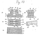
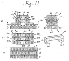
- Fig. 9, Fig. 10 and Fig. 11 show embodiments of linear motor of the invention. There, component elements of the linear motor except the permanent magnet in each Fig. are the same for the first embodiment of the invention in Fig. 3 and explanation is omitted giving the same number to them.
- FIG. 9 Fig. 10 and Fig. 11, (A) is a vertical sectional view, (B) is a sectional view of D-D line of (A), (C) is a sectional view of E-E line of (A), (D) is F-F sectional view of F-F line of (A) and (E) is an oblique view of the permanent magnet.
- movable element 5 has permanent magnet 50 which is positioned between a pair of iron cores 51 and 52 to provide bias magnetic flux, and permanent magnets 503, 504, 505 which are positioned between each magnetic core part between a pair of iron cores 51 and 52.
- Said permanent magnets 503, 504 and 505 have the same dimension. As the direction of their magnetizing is adjusted to that of permanent magnet 50 and magnetic flux generated in permanent magnet 50 does not leak from adjacent field core 511 to 521 (from 512 to 522, from 513 to 523) and induced passing by the field core part, and thus, effectively utilized.
- a part of magnetic flux generated in further added permanent magnets 503, 504 'and 505 becomes bias magnet flux of the linear motor and it also enlarges a total amount of magnetic flux.
- permanent magnet 503, 504 and 505 works for thrust force in multiple way and thrust force can be increased about 30% according to a sample made by the inventor. That is, the linear motor with larger thrust force than that of prior arts can be easily realized without changing its external dimensions at all.
- permanent magnets 50, 503 and 504 correspond to permanent magnets 50, 503 and 504 in Fig. 9 and 503 and 504 have the same dimension.
- the size of permanent magnet 506 is smaller than that of permanent magnet 503 and 504 and it corresponds to permanent magnet 505 in Fig. 9.
- permanent magnets 503, 504, 506 can reduce the leakage of magnetic flux between adjacent fields cores of the adjacent iron cores like embodiment in Fig. 9. Also, linear motor's thrust force can be increased by increasing a total amount of bias magnetic flux extending the effective area of the permanent magnet. In addition to that, in the embodiments in Fig. 10, the amount of bias magnetic flux which passes by magnetic teeth on the central fields cores is adjusted by designing the dimension of permanent magnet 506 positioned between central field core parts at will to adjust thrust force generated in this part. By this measure, thrust force generated in each magnetic teeth group on each field core can be balanced and an effective linear motor can be realized. In the embodiment of Fig. 11, permanent magnets 50, 503 and 504 correspond to those 50, 503 and 504 in Fig.
- the linear motor of the invention has superior features that the balance of thrust force can be maintained between each magnetic teeth group while increasing thrust force at the same time, compared with prior arts.
- the small linear motor with large thrust force can be easily realized without damaging advantages of prior arts at all.
- the major part of adjacent iron cores and the field core permanent magnet are made of different materials, but there is no affect on characteristics even if they are unified in various forms. All forms of permanent magnets in the Figures are rectangular bodies, but it is not necessary to limit their forms to rectangular bodies and they can be designed at will according to forms of iron cores and field cores within the scope of the invention.
Description
- This invention relates to a linear motor in which a movable element shifts linearly.
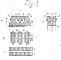
- Fig. 1 is a block diagram which shows a prior art of the linear motor. (A) is a vertical sectional view, (B) is a sectional view of C-C line of (A), (C) is sectional view of A-A line of (A) and (D) is sectional view of B-B line. In Fig. 1, 1 is a guiding path composed of magnetic materials, 2 is the movable element which faces the guiding path through a minute gap, which is a three phase linear motor here.
Movable element 2 is composed of a pair ofiron cores permanent magnet 20 which is positioned between a pair ofiron cores coils adjacent field cores iron cores path 1 are on edges which face each field core's guidingpath 1. Magnetic teeth's phases offield cores iron cores iron cores path 1 has rows ofmagnetic teeth 11 and 12 which has the same pitch P as magnetic teeth oniron cores movable element 2. Rows ofmagnetic teeth 11 and 12 are arranged shifting phases as much as 1/2P in the direction of saidmovable element 2's movement. - In a device which has an above construction, said
permanent magnet 20 is magnetized in the direction as shown in Fig. (B) and magnetic flux generated by saidpermanent magnet 20 returns topermanent magnet 20 throughfield cores iron core 21, guidingpath 1's row of magnetic teeth 11 which faces magnetic teeth a, b and c through a minute gap and passing from row ofmagnetic teeth 12, through a minute gap, to each magnetic tooth ofiron core 22 and eachfield core movable element 2's magnetic teeth and guidingpath 1's magnetic teeth. When exciting current is conducted to saidcoil 31, magnetic flux generated by the exciting current is overlapped with said bias magnetic flux. - When exciting current is conducted to coil 31 in the direction in which magnetic flux between
field core 211 on theiron core 21 side and guidingpath 1 is increased, magnetic flux betweenfield core 221 on theiron core 22 side and guidingpath 1 is reduced. As a result,movable element 2's field core 211 and guidingpath 1 pull with each other andmovable element 2 is retained in a position shown in Fig. 1(S) in which its gap's reactance is minimized. - Then, when exciting current is conducted to coil 32 in the direction in which magnetic flux between
field core 212 on theiron core 21 side and guidingpath 1 is increased, both of them pull with each other, thusmovable element 2 shifts to the right.Movable element 2 shifts as much as 1/3P, as phases betweenfield core 211's magnetic teeth a, b and c andfield core 212's magnetic teeth a, b and c shift as much as 1/3P. - In the same manner, when exciting current is conducted to coil 33, 31, 32, 33, ....... respectively, the movable element shifts to the right respectively with 1/3P as a minimum shifting length. When exciting current is conducted to coil 33, 32 and 31 respectively,
movable element 2 shifts to the left. - On the other hand, if the direction of exciting current conducted to coils 31, 32 and 33 is reversed from said case, magnetic flux between
field core 221 and guidingpath 1 is increased in as shown in Fig. 1 (8) and they pull with each other. Therefore, when exciting current is respectively conducted to coil 32, 33, 31, ...... , in the reverse direction from said case,movable element 2 shifts to the right with 1/3P as a minimum shifting length. Also, when current is conducted to coils 33, 32, 31, ...... respectively in the reverse direction from said case,movable element 2 shifts to the left with 1/3P as a minimum shifting length. As rows ofmagnetic teeth 11 and 12 of guidingpath 1 are formed with phases of teeth are shifted as much as 1/2P, when the direction of exciting current to be conducted to coils is positive and negative (reversed stopping position ofmovable element 2 are not overlapped with each other and are shifted as much as 1/6P). That is,movable element 2 shifts as much as minimum shiftinglength 1/6P by switching exciting current to be conducted to coils 31, 32 and 33 and changing the direction of exciting current to energize coils respectively. - This operation will be more specifically explained. With respect to the phase of the magnetic teeth of the
field core 211, the phases of thefield cores movable element 2 can be shifted with the minimum shifting length of 1/6P by flowing exciting currents throughcoils field cores path 1 in the order named. In other words, exciting currents are flown in turn throughcoil 31 in positive direction, throughcoil 33 in negative direction, throughcoil 32 in positive direction, through 31 in negative direction, through 33 in positive direction, and through 32 in negative direction. - To improve the thrust force of this type of linear motor, it is very effective to increase bias magnetic flux between magnetic teeth on the movable element iron cores and these on the guiding path. One of means to expand bias magnetic flux is to increase a total magnetic flux generated by the permanent magnet which provides bias magnetic flux. Another means is to try to minimize leakage flux which does not. contribute to the linear motor thrust force among magnetic flux generated by the permanent magnet.
- Considering a prior art which has a construction as shown in Fig. 1 in said point of views, small distance W, between
adjacent field cores iron cores - If said distance W, is expanded, it is possible to reduce leakage magnetic flux, but width W2 of guiding
path 1 should be also expanded accordingly. Expansion of width W2 of guidingpath 1 is made on the entire length of guidingpath 1, thus weight of the guiding path increases greatly. Due to this increase, weight of a device into which the motor is integrated naturally increases. Also, for X-Y plotter into which the motor is integrated, weight increase of the guiding path gives a lot of adversable effect on the velocity of plotting, as a motor of one spindle sets shift positioning of a motor of another spindle with its guiding path. - Movable element magnetic teeth of the prior art as shown in Fig. 1 is difficult to be machined precisely in terms of dimension. Generally, movable element magnetic teeth are machined by feeding a machining knife by magnetic teeth pitch. When the number of linear motor's phases is increased to 5, 6, ...... , the type of magnetic teeth with different phases on the same iron core is increased to 5, 6, ...... and their phase difference become detailed to 2πI5 and 2πI6, ... . . . , thus feeding pitch of the machining knife should be changed many times during machining, therefore there is a defect that machining cannot be made precisely.
- As a result the linear motor is subject to the deterioration of precision of positioning more easily.
- Also, thrust force for shifting generated in each field core is actually very uneven in this type of linear motor. The biggest reason for this is the amount of bias magnetic flux wihch passes each field core is very different. This difference is mainly caused by leakage flux. Fig. 2 is the oblique view of
movable element 2 to explain leakage magnetic flux of the prior art shown on Fig. 1.Half cylinder part iron cores central field cores field cores - In addition to that, magnetic flux of coils are different depending on each field core. This is mainly due to the difference of magnetic resistance depending on the length of iron core magnetic path. For instance, in the case of
iron core 21, magnetic flux generated bycoil 32 which is wound aroundfield core 212 at the center ofiron core 21 separately goes aroundfield core coil 32, but magnetic flux, for instance, ofcoil 31 wound aroundoutside field core 211, goes around separatelyfield core 212 which is next to 211 and, further,field core 213 which is next to 212. Thus, in latter case, iron core's magnetic path is slightly longer and magnetic flux of outside field cores tends to be slightly smaller than that of the central part and field cores. - It is becoming apparent that deviation of thrust force caused by each field core is mainly affected by two kinds of deviation, deviation of bias magnetic flux and that of magnetic flux caused by coils. Deviation of magnetic flux caused by coils can be almost neglected by lowering iron core's reluctance, but deviation of bias magnetic flux is relatively large and, as a consequence, the linear motor's thrust force of the prior art is deviated to a large extent.
- JP-A-56-83259 (Patent Abstracts of Japan, No. 149, 19 September 1981) discloses a linear motor comprising: a guiding path having magnetic teeth provided at a constant pitch P in the longitudinal direction of said guiding path; and a movable element which is in spaced opposed relation to said guiding path with a small gap therebetween and movable along said guiding path, wherein said movable element comprises: a pair of iron core arrays spaced from each other in said longitudinal direction; means connected between said pair of iron core arrays for supplying bias magnetic flux thereto; and means electrically associated with said pair of iron core arrays for energizing thereof, each of said pair of iron core arrays comprising a plurality of field cores disposed side by side in a transverse direction to said longitudinal direction, each of said field cores having on a surface facing said guiding path teeth provided at said pitch P in said longitudinal direction. However, although this motor operates satisfactorily the need still exists for a linear motor with higher efficiency and performance and to improve the manufacturing methods of the magnetic teeth and precision in teeth dimensions.
- This invention is to provide a novel linear motor in which defects of the prior art are eliminated.
- Thus an object of the invention is to provide a linear motor with high efficiency, high performance and large thrust force. Another object of the invention is to provide a linear motor which is constructed so that machining work of magnetic teeth and dimension precision can be easily improved.
- A further object of the invention is to provide a smooth and high grade linear motor which has even thrust force for shifting generated by each field core.
- The present invention provides a linear motor as described in JP-A-56-83259 but characterized in that: said teeth on the field cores of each of the pair of iron core arrays have the same spatial phase, and the phase of the teeth on the field cores of one of the pair of iron core arrays is shifted in spatial phase by 1/2 - P relative to the teeth on the field cores of the other of the pair of iron core arrys; that the magnetic teeth of said guiding path consists of parallel rows of magnetic teeth aligned with respective parallel field cores of the arrays, each row of said parallel rows of magnetic teeth being shifted in spatial phase by (n/m) - P relative to an adjacent row, where m is the number of phases of said linear motor and n being an integer, and m>n; and that said field cores of the arrays are arranged in pairs in the longitudinal direction with each pair consisting of one field core from each array, the field cores of each pair being aligned with a respective row of the guiding path, and the energizing means being arranged to subsequently energize said pairs of field cores.
- Since in accordance with the invention the field cores of each iron core array have the same spatial phase, it is not necessary to change the feeding pitch of a machining knife during manufacture, but only when changing the cutting operation to the other iron core array. Hence machining work is simplified and precision is improved. By'spatial phase', it will be understood that two teeth having the same position in the direction of movement have the same phase, and for teeth having a recurrent spacing of P therebetween in the direction of movement, the space P constitutes a single phase cycle, with a phase difference equal to P. Thus teeth having a spacing not equal to P or a multiple thereof are said to be out of phase.
- During design and manufacture of the motor, tha distance between a pair of iron core arrays can be extended. Leakage magnetic flux from the field cores of one iron core array to the other iron core array can be largely reduced by extending this distance. Thus, magnetic flux generated by energizing means can be effectively used. This increases bias magnetic flux and contributes to improving thrust force. When the device has such construction, the width of the guiding path is not changed and its weight is hardly affected.
- In the linear motor of the invention, areas of magnetic teeth on a pair of iron core arrays and magnetic teeth on the guiding path can be designed at will, as the number of magnetic teeth can be easily increased in the direction of the movable element's movement. Therefore, it is easy to avoid magnetic saturation caused by excessive bias magnetic flux. Also, there is almost no increase in the guiding path's weight, as the width of the guiding path does not change at all even when the number of movable element magnetic teeth are increased in the direction of the movable element's movement. Hence thrust force and efficiency may be improved.
- These objects and features of the invention can be understood more clearly by the following detailed description taken in connection with the accompanying drawings.
-
- Fig. 1(A), (B), (C) and (D) are sectional views of each part showing an example of the linear motor prior art.
- Fig. 2 is an oblique view to describe leakage magnetic flux of the linear motor prior art.
- Fig. 3(A), (B), (C) and (D) are sectional views of each part showing embodiments of the invention.
- Fig. 4 and Fig. 5 are block diagrams of major parts showing other embodiments of the invention.
- Fig. 6(A) and (B) are a plain view and a sectional view of major parts showing embodiments of the guiding path which can be used for the invention.
- Fig. 7(A), (B), (C) and (D) are sectional views of each part showing other embodiments of the invention.
- Fig. 8 is a sectional view of major parts showing other embodiments of the invention.
- Fig. 9(A), (B), (C), (D) and (E), Fig. 10(A), (B), (C), (D) and (E) and Fig. 11 (A), (B), (C), (D) and (E) are sectional views of each part and an oblique view of major parts showing other embodiments of the invention.
- Detailed description of the preferred embodiments
- Fig. 3 is a block diagram showing embodiments of the invention.
- (A) is a vertical sectional view.
- (B) is a sectional view of D-D line of (A).
- (C) is a sectional view of E-E line of (A).
- (D) is a sectional view of F-F line of (A).
- In Fig. 3,
movable element 5 is composed of a pair ofiron core arrays permanent magnet 50 which is positioned between a pair ofiron cores adjacent field cores iron cores 51 and 52 (512 and 522, 513 and 523). - Plural magnetic teeth with pitch P are formed on the edge which faces the guiding path of (511, 512,513, 521, 522 and 523). As for the relationship of phases between each magnetic tooth, magnetic teeth on
iron core 51'sfield cores iron cores adjacent field cores 511 and 52T(512 and 522, 513 and 523) are shifted as much as 1/2 -P. Guiding path 4 is composed of magnetic materials and plural magnetic teeth with the same pitch P as that formovable element 5's magnetic teeth are on the surface which faces magnetic teeth on saidmovable element 5. Plural rows of said guidingpath 4's magnetic teeth exist along the direction of saidmovable element 5's movement (in this embodiment, three rows: 41, 42 and 43). As for the relationship of phases between rows ofmagnetic teeth movable element 5's movement (m is the number of phases of the linear motor and n is an integer where relationship is m>n). In this embodiment, rows ofmagnetic teeth 41 and 42 (42 and 43, 43 and 41) are positioned shifting phases as much as 1/3P. - In the linear motor with such construction, if
permanent magnet 50 is magnetized in the direction as shown in Fig. 3(A), magnetic flux is generated betweenmovable element 5 and guidingpath 4 in the direction as shown in 501 of the same Fig. That is, there is bias magnetic flux in the direction towardiron core 51, guidingpath 4 andiron core 52. When exciting current is conducted tocoil 61 wound aroundfield cores field core 511 and guidingpath 4'srow 41 of magnetic teeth and magnetic flux decreases betweenfield core 521 and guidingpath 4'srow 41 of magnetic teeth. As a result,movable element 5'sfield core 511 and guidingpath 4's row of magnetic flux pull with each other.Movable element 5 is retained in the position as shown in Fig. 3(A). Then, when exciting current is conducted to coils wound aroundfield cores field core 512 and guidingpath 4's row ofmagnetic teeth 42 and pull with each other, thusmovable element 5 shifts to the right.Movable element 5 shifts as much as 1/3P, as phases of row ofmagnetic teeth coils movable element 5 shifts to the right respectively with 1/3 - P as a minimum shifting length. When exciting current is conducted tocoils movable element 5 shifts to the left. On the other hand, when the direction of exciting current to be conducted tocoils iron core 52's field core 521 (522, 523) and guidingpath 4'srow coils movable element 5 shifts to the right with 1/3P as a minimum shifting length. Also, current is conducted tocoils movable element 5'sfield cores 511 and 521 (512 and 522, 513 and 523) are shifted as much as 1/2 . P in the direction ofmovable element 5's movement, when direction of exciting current to be conducted to coils is positive and negative (reverse direction), stopping positions ofmovable element 5 are not overlapped and shifted as much as 1/6P. That is,movable element 5 shifts with 1/6P as a minimum shifting length by'switching exciting current to be conducted tocoils - This operation will be more specifically explained. Assuming that the phase of the magnetic teeth of the
field core 511 with respect to the phase of the teeth on the fixedelement 4 is zero, the phases of thefield cores movable element 2 can be shifted with the minimum shifting length of 1/6P by flowing exciting currents throughcoils field cores path 1 in the order named. In other words, exciting currents are flown in turn throughcoil 63 in positive direction, throughcoil 61 in negative direction, throughcoil 62 in positive direction, through 63 in negative direction, through 61 in positive direction, and through 62 in negative direction. Now, structural features of the linear motor of the invention is described. - In Fig. 3, distance between a pair of
iron cores movable element 5'siron core 51 toiron core 52's field core can be largely reduced by extending W. Thus, magnetic flux generated bypermanent magnet 50 can be effectively used. This increases bias magnetic flux and contributes to improving thrust force. When the device has such construction, the width of the guiding path is not changed and its weight is hardly affected. - In the linear motor of the invention, although the width of magnetic teeth is shortened, areas of magnetic teeth on a pair of
iron cores - As explained, the linear motor of the invention can increase thrust force improving efficiency and this does not increase guiding path's weight.
- According to a sample made by the inventor, it has been confirmed that the linear motor of the invention has the equivalent width and weight to that of the guiding path and almost equivalent dimension and weight to that of the movable element, and thrust force is increased by 30%-40%. Therefore, it can be said that the linear motor of the invention is most suitable for the X-Y plotter, as mentioned before.
- Further, the linear motor
movable element 5's construction of the invention is very advantageous in terms of defects of prior arts that it is difficult to precisely machine movable element magnetic teeth. That is, among plural field cores ofmovable element 5, phase of each magnetic tooth on the field cores of the same iron core is the same, thus, no matter how the number of linear motor's phase increases, there is only one kind of magnetic teeth on the same iron core in terms of phase, therefore, it is necessary to change the feeding pitch of the machining knife only when settingphase difference 1/2 - P in a pair of iron cores. Therefore, the construction of the linear motor movable element of the invention is really excellent in which machining work of magnetic teeth is improved and precision of dimension can be easily improved. In above description, operation of the linear motor of the invention is explained as a step motor, but it does not damage advantages of the invention even when position detecting means, non-contact current feeding means and so on are installed there to use it as a electronic commutator linear motor. - Fig. 4 and Fig. 5 are block diagram of major parts showing other embodiments of the linear motor of the invention.
- In embodiments of Fig. 3,
permanent magnet 50 is positioned between a pair ofiron cores - It is also possible to provide bias magnetic flux by winding
coil 60 around the magnetic path betweeniron cores - As for
coils field cores 511 and 521 (512 and 522, 513 and 523), coils 611 and 612 can be wound aroundfield cores field cores - When distance between a pair of
iron cores field cores 511 and 521 (512 and 522, 513 and 523), the length of coils is extended and ohmic loss increases. In the view point of linear motor's efficiency, it is desirable that ohmic loss is as small as possible. - The embodiment of Fig. 5 is very effective to reduce ohmic loss as the length of coils can be shortened.
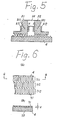
- Fig. 6 is an embodiment to realize, with ease and good precision, guiding
path 4's construction of linear motor's embodiments of the invention in Fig. 3, Fig. 4 and Fig. 5. Fig 6(A) is a plain view of the guiding path and (B) is a sectional view of G-G line of (A). - In Fig. 6, laminated material (hereafter it is referred to as an etching lamination) made of magnetic materials with plural slits is fixed to
substrate 72 made of magnetic materials by etching, etc. to form magnetic teeth equivalently, and thus realizing guidingpath 4. Plural rows (in this embodiment, three rows: 711,712 and 713) ofetching lamination 71's slits are formed along the direction ofmovable element 5's movement. Phases of row of slits 711, 712 and 713 are shifted bv - - - - - - - n/m · v in the direction of said movable element's movement (provided that m is the number of phase of the linear motor and n is integer, m>n and they are shifted ------by 1/3 - P with each other in the embodiment). - The precision of dimension of
etching lamination 71's each slit depend on the precision of etching determined by the quality of laminated material and thickness t. Therefore, even when the row of magnetic teeth of guidingpath 4 is increased to 5 rows, 6 rows, ...... and become complicated, as the number of phases of the linear motor increases to 5, 6, ...... , the level of etching lamination's production is not affected, precision is not deteriorated and production can be made very easily. The etching lamination's slits of the embodiment penetrate the laminated material, but there is no doubt that half etching is acceptable, and thus, it has same advantages in the view point of precision and easy production. - Although it is not shown in figure, said advantages are not damaged at all even when half etching is directly made to
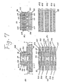
substrate 72 made of magnetic materials to produce guidingpath 4 without usingetching lamination 71. - Fig. 7 is a block diagram showing other embodiments of the invention. (A) is a vertical sectional view, (B) is a sectional view of H-H line of (A), (C) is a sectional view of I-I line of (A) and (D) is a sectional view of J-J line of (A).
- In Fig. 7,
movable element 500 is composed of a pair ofiron cores permanent magnet 57 which is positioned between these iron cores to provide bias magnetic flux and plural coils. (There are five here: 621, 622, 623, 624 and 625) wound aroundadjacent field cores 531 and 541 (532 and 542, 533 and 543, 534 and 544, 535 and 545) of a pair of iron cores. Magnetic teeth groups with pitch P is formed on the edge of each field core which faces the guiding path. As for the relationship of phases between each magnetic teeth group, magnetic teeth oniron core 53's field core 531,532,533,534 and 535 have the same phase, magnetic teeth oniron core 54'sfield cores adjacent field cores 531 and 541 (532 and 542, 533 and 543, 534 and 544, 535 and 545) are shifted as much as 1/2 - p. The magnetic teeth group of each offield cores field cores Coils field cores coild 623 wound aroundfield cores coils 621 and 625 (622 and 624). Guidingpath 40 is made of magnetic materials and plural magnetic teeth with the same pitch as formovable element 500's magnetic teeth are formed on a surface which faces magnetic teeth on saidmovable element 500. There are plural rows (in this embodiment, five rows: 411, 412, 413, 414, 415) of magnetic teeth on said guidingpath 40 along the direction of saidmovable element 500's movement. As for the relationship of phases between these rows of magnetic teeth, rows ofmagnetic teeth 411 and 415 (412 and 414) have the same phase, rows ofmagnetic teeth magnetic teeth 411 and 412 (412 and 413, 413 and 411). That is, the linear motor's embodiment of the invention in Fig. 7 is a three phase motor. Considering the relationship of phases of magnetic teeth on eachfield core movable element 500 to guidingpath 40's each row of magnetic teeth,field cores 531 and 535 (532 and 534, 541 and 545, 542 and 544) have the same phase and all others have different phases. - As described, if
permanent magnet 57 is magnetized in the direction as shown in Fig. 7(A) in the linear motor, magnetic flux is generated in. the direction as shown in 502 of the same Fig. betweenmovable element 500 and guidingpath 40. That means there is bias magnetic flux towardsiron core 53, guidingpath 40 andiron core 54. When exciting current is conducted tocoils field cores field cores path 40's rows ofmagnetic teeth field cores 541, 545 and guidingpath 40's rows ofmagnetic teeth movable element 500'sfield cores path 40's rows ofmagnetic teeth movable element 5 is retained in the position as shown in Fig. 7(A) in which reluctance of its gap is minimized. Then, when exciting current is conducted tocoils field cores field cores path 40's rows of magnetic teeth 412,414 increases and they pull with each other, thusmovable element 500 shifts to the right.Movable element 500 shifts as much as 1/3P, as rows of magnetic teeth on the guidingpath coils movable element 500 shifts to the right respectively with 1/3P as a minium shifting length. When exciting current is conducted tocoils movable element 500 shifts .to the left. - On the other hand, when the direction of exciting current to be conducted to
coils iron core 54's field core 541 (542, 543, 544, 545) and guidingpath 40's row of magnetic teeth 411 (412, 413, 414, 415) increases. Therefore, when exciting current is conducted, in the reverse direction from the said case, tocoils movable element 500 also shifts to the right with 1/3P as a minimum shifting length. When current is conducted, in the reverse direction from the said case, tocoils movable element 500 shifts to the left with 1/3P as a minimum shifting length. As phases of magnetic teeth onmovable elements 500'sfield cores 531 and 541 (532 and 542, 533 and 543, 534 and 544, 535 and 545) are shifted as much as 1/2P in the direction ofmovable element 500's movement, when the direction of exciting current to be conducted to coils is positive and negative (reverse direction), stopping positions ofmovable element 500 are not overlapped and are shifted as much as 1/6P.Movable element 500 shifts with 1/6P as a minimum shifting length by changing the direction of exciting current to magnetize coils respectively. Explanation is given only on single energizing in above description, but it is needless to say that polyphase energizing can increase thrust force in the same manner as for the prior art in Fig. 1. - Thus explained linear motor of the invention has the following superior features.
- In Fig. 7, magnetic teeth having the same phase which generate thrust force simultaneously on the left and right (in the direction of increment) of the
movable element 500's gravity center (generated to guidingpath 40's magnetic teeth) are separately positioned on the linear motor, and furthermore, distances from separately positioned magnetic teeth to the gravity center are the same. Thus, thrust force generated in each magnetic teeth can effectively work in the forwarding direction without giving rotation moment tomovable element 500 and, thus, smooth operation can be realized. Therefore, this linear motor is suitable especially when large thrust force and smooth operation are required, when it is used as a step motor for positioning equipments for which high precision is required even though it is small in its size and thrust force and when it is used as a servo-motor to equipments for which smooth movements are required. Further, in terms of production, the linear motor can be polyphased easily. There is only one kind of phase of magnetic teeth on eachiron core movable element 500 in the same iron core and feeding pitch of a machining knife should be changed only when settingphase difference 1/2P in a pair of iron cores like the first embodiment of the invention in Fig. 3, and thus, magnetic teeth with extremely high precision can be formed and polyphase does not damage precision. - There is no doubt that when guiding
path 4's rows of magnetic teeth are formed using a method such as etching, etc., the level of work and precision of machining are not changed and it can be produced easily no matter how many rows are formed. In the embodiment of the invention in Fig. 7, construction in which twofield cores field cores 531 and 541 (532 and 542, 533 and 543, 534 and 544, 535 and 545), but they can be separately wound around each field core to connect then in serial. Also, it is needless to say that a coil can be used as means to provide bias magnetic flux instead of the permanent magnet. - In each embodiment of the linear motor of the invention in Fig. 3, Fig. 4, Fig. 5 and Fig. 7, deviation of thrust force generated in each field core, which is one of defects of prior arts, is not referred, but that point is explained in the following embodiment.
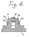
- Fig. 8 is another embodiment of the linear motor of the invention. This drawing especially shows the movable element in terms of magnetic teeth. This drawing is basically corresponded to the first embodiment of the invention, Fig. 3(C). In the Fig. 8, 50 is the permanent magnet for bias magnetic flux and 55 and 56 are a pair of iron cores, 551, 552, 553 and 561, 562, 563 are field cores with magnetic teeth on said
iron cores arrow 64 shows the direction of the movable element's movement. As this Fig. shows,field cores central field cores 552 or 562 have the larger area of magnetic teeth than these central field cores. In this case, the width of magnetic teeth has widened outside field cores more than central field cores, and it has consequently enlarged the area of magnetic teeth part. When it is constructed in this manner, areas of magnetic teeth and the guiding path's rows of magnetic teeth are enlarged, reluctance of the gap is reduced, more bias magnetic flux can be induced and it becomes possible to compensate leakage, thus, even thrust force can be realized as a result. In the embodiment, the area of the magnetic teeth part is adjusted by the width of its teeth, thus, thrust force of each field core can be equalized quite precisely. Also, of course, the same effects can be achieved by changing the area of the magnetic teeth part adjusting the number of teeth and setting the same width for teeth. However, adjustment is not so precise as for former case. - Not only for the embodiment in Fig. 8, it is good to provide the largest area for the most outside field core magnetic teeth part in cases in which a pair of iron cores have many field cores such as 4 and 5.
- Fig. 9, Fig. 10 and Fig. 11 show embodiments of linear motor of the invention. There, component elements of the linear motor except the permanent magnet in each Fig. are the same for the first embodiment of the invention in Fig. 3 and explanation is omitted giving the same number to them.
- In Fig. 9, Fig. 10 and Fig. 11, (A) is a vertical sectional view, (B) is a sectional view of D-D line of (A), (C) is a sectional view of E-E line of (A), (D) is F-F sectional view of F-F line of (A) and (E) is an oblique view of the permanent magnet.
- Firstly, in the embodiment in Fig. 9,
movable element 5 haspermanent magnet 50 which is positioned between a pair ofiron cores permanent magnets iron cores permanent magnets permanent magnet 50 and magnetic flux generated inpermanent magnet 50 does not leak fromadjacent field core 511 to 521 (from 512 to 522, from 513 to 523) and induced passing by the field core part, and thus, effectively utilized. A part of magnetic flux generated in further addedpermanent magnets - As above description shows, the effect of
permanent magnet permanent magnets permanent magnets permanent magnet 506 is smaller than that ofpermanent magnet permanent magnet 505 in Fig. 9. - These
permanent magnets permanent magnet 506 positioned between central field core parts at will to adjust thrust force generated in this part. By this measure, thrust force generated in each magnetic teeth group on each field core can be balanced and an effective linear motor can be realized. In the embodiment of Fig. 11,permanent magnets permanent magnets - As explained, the linear motor of the invention has superior features that the balance of thrust force can be maintained between each magnetic teeth group while increasing thrust force at the same time, compared with prior arts. The small linear motor with large thrust force can be easily realized without damaging advantages of prior arts at all. In linear motors of the invention in Fig. 9, Fig. 10 and Fig. 11, the major part of adjacent iron cores and the field core permanent magnet are made of different materials, but there is no affect on characteristics even if they are unified in various forms. All forms of permanent magnets in the Figures are rectangular bodies, but it is not necessary to limit their forms to rectangular bodies and they can be designed at will according to forms of iron cores and field cores within the scope of the invention.
Claims (9)
Applications Claiming Priority (8)
| Application Number | Priority Date | Filing Date | Title |
|---|---|---|---|
| JP67575/82 | 1982-04-21 | ||
| JP6757582A JPS58186363A (en) | 1982-04-21 | 1982-04-21 | Linear motor |
| JP129338/82 | 1982-07-23 | ||
| JP12933882A JPS5921272A (en) | 1982-07-23 | 1982-07-23 | Linear motor |
| JP13067282A JPS5921273A (en) | 1982-07-26 | 1982-07-26 | Linear motor |
| JP130672/82 | 1982-07-26 | ||
| JP13343282A JPS5925571A (en) | 1982-07-29 | 1982-07-29 | Linear motor |
| JP133432/82 | 1982-07-29 |
Publications (2)
| Publication Number | Publication Date |
|---|---|
| EP0093547A1 EP0093547A1 (en) | 1983-11-09 |
| EP0093547B1 true EP0093547B1 (en) | 1986-09-17 |
Family
ID=27464873
Family Applications (1)
| Application Number | Title | Priority Date | Filing Date |
|---|---|---|---|
| EP83302275A Expired EP0093547B1 (en) | 1982-04-21 | 1983-04-21 | Linear motor |
Country Status (3)
| Country | Link |
|---|---|
| US (1) | US4504750A (en) |
| EP (1) | EP0093547B1 (en) |
| DE (1) | DE3366213D1 (en) |
Families Citing this family (31)
| Publication number | Priority date | Publication date | Assignee | Title |
|---|---|---|---|---|
| US4761574A (en) * | 1983-05-18 | 1988-08-02 | Shinko Electric Co., Ltd. | Linear pulse motor |
| US4661730A (en) * | 1984-03-28 | 1987-04-28 | Shinko Electric Co., Ltd | Linear pulse motor |
| US4594520A (en) * | 1984-04-26 | 1986-06-10 | Shinko Electric Co., Ltd. | Linear pulse motor |
| JPS6176239A (en) * | 1984-09-25 | 1986-04-18 | Hiroshi Teramachi | Xy table with linear motor |
| JPS61161952A (en) * | 1985-01-09 | 1986-07-22 | Yaskawa Electric Mfg Co Ltd | 3-phase linear inductor type motor |
| JPS61185059A (en) * | 1985-02-09 | 1986-08-18 | Amada Co Ltd | Linear pulse motor |
| JPS61199278A (en) * | 1985-02-28 | 1986-09-03 | Tokyo Juki Ind Co Ltd | Driving device for disk drive |
| SE457043B (en) * | 1985-04-29 | 1988-11-21 | Facit Ab | LINE STEP ENGINE |
| JPH0687651B2 (en) * | 1986-01-14 | 1994-11-02 | オムロン株式会社 | Linear pulse motor |
| US4772841A (en) * | 1986-03-08 | 1988-09-20 | Shinko Electric Co., Ltd. | Stepping motor and driving method thereof |
| DE68910649T2 (en) * | 1988-11-22 | 1994-05-19 | Shinko Electric Co Ltd | Actuator with strong magnetic pushing force. |
| JPH04276363A (en) * | 1991-03-01 | 1992-10-01 | Hitachi Ltd | Disk device and linear actuator |
| WO1999041825A1 (en) * | 1998-02-13 | 1999-08-19 | Kabushiki Kaisha Yaskawa Denki | Linear motor |
| US5965962A (en) * | 1998-02-20 | 1999-10-12 | Northern Magnetics, Inc. | Linear stepper motor |
| SE518110C2 (en) * | 1999-12-23 | 2002-08-27 | Hoeganaes Ab | Stator and rotor for an electric machine |
| US6756705B2 (en) * | 2000-02-10 | 2004-06-29 | Tri-Tech., Inc | Linear stepper motor |
| DE10043120A1 (en) * | 2000-08-31 | 2002-04-11 | Wolfgang Hill | Electrical machine for high magnetic reversal frequencies |
| CA2435249A1 (en) * | 2001-01-23 | 2002-08-01 | Harrie R. Buswell | Wire core inductive devices having a biassing magnet and methods of making the same |
| CA2438229A1 (en) * | 2001-02-12 | 2002-08-22 | Tri-Tech, Inc. | Linear stepper motor, magnetizing fixture, and methods |
| JP3894297B2 (en) * | 2001-02-28 | 2007-03-14 | 富士電機機器制御株式会社 | Linear actuator |
| US20050108869A1 (en) * | 2003-05-16 | 2005-05-26 | Shuen-Shing Hsiao | Method for manufacturing teeth of linear step motors |
| MY136646A (en) * | 2004-05-11 | 2008-11-28 | Toshiba Elevator Kk | Magnet unit, elevator guiding apparatus and weighing apparatus |
| DE102006005046A1 (en) * | 2006-02-03 | 2007-08-09 | Siemens Ag | Electric machine with uneven pole teeth |
| DE102006009439A1 (en) * | 2006-03-01 | 2007-09-06 | Siemens Ag | Electric machine with insertion device for a permanent magnet between Polzahnhälften and corresponding manufacturing method |
| DE102006012736A1 (en) * | 2006-03-17 | 2007-09-20 | Siemens Ag | Electric machine |
| CN102239626B (en) * | 2009-09-08 | 2015-01-28 | 莫戈公司 | Stepping motors with small step intervals |
| US10020716B2 (en) * | 2010-03-31 | 2018-07-10 | The Boeing Company | Transverse flux induction motor with passive braking system |
| US8803371B2 (en) * | 2011-07-11 | 2014-08-12 | Baldor Electric Company | Secondary for linear drive motor comprising sheet of highly permeable magnetic material having synchronized motor teeth, encoder teeth, and commutation tracks integrally formed therein |
| EP2963497B1 (en) * | 2014-06-30 | 2019-10-16 | Dr. Johannes Heidenhain GmbH | Drive for an XY-Table and XY-Table |
| US9956969B2 (en) * | 2015-04-30 | 2018-05-01 | The Boeing Company | Brake device |
| EP4055696B1 (en) | 2019-11-07 | 2023-09-20 | Hyperloop Technologies, Inc. | Electrical windings for a low pressure environment |
Family Cites Families (11)
| Publication number | Priority date | Publication date | Assignee | Title |
|---|---|---|---|---|
| US3869625A (en) * | 1971-09-08 | 1975-03-04 | Bruce A Sawyer | Plural axis linear position |
| US3867676A (en) * | 1973-09-20 | 1975-02-18 | Ibm | Variable reluctance linear stepper motor |
| DE2413410A1 (en) * | 1974-03-18 | 1975-10-02 | Siemens Ag | Sync. linear motor with DC excited inductor - has two laminated cores coupled by rear yoke with polyphase AC winding in open slots |
| DE2429492C3 (en) * | 1974-06-20 | 1979-04-26 | Elmeg-Elektro-Mechanik Gmbh, 3150 Peine | Electric motor that can be operated step by step or continuously, in particular a step motor for driving a roller counter |
| JPS5223606A (en) * | 1975-08-15 | 1977-02-22 | Kokusai Denshin Denwa Co Ltd <Kdd> | Reciprocal steppin motion mechanism |
| US4286180A (en) * | 1978-07-20 | 1981-08-25 | Kollmorgen Technologies Corporation | Variable reluctance stepper motor |
| JPS591059B2 (en) * | 1979-02-22 | 1984-01-10 | 横河電機株式会社 | linear pulse motor |
| JPS5854737B2 (en) * | 1979-03-05 | 1983-12-06 | 横河電機株式会社 | linear pulse motor |
| JPS5855748B2 (en) * | 1979-06-21 | 1983-12-12 | 横河電機株式会社 | linear pulse motor |
| JPS5683259A (en) * | 1979-12-11 | 1981-07-07 | Matsushita Electric Ind Co Ltd | Linear stepping motor |
| JPS5725151A (en) * | 1980-07-22 | 1982-02-09 | Matsushita Electric Ind Co Ltd | Linear motor |
-
1983
- 1983-04-20 US US06/486,965 patent/US4504750A/en not_active Expired - Fee Related
- 1983-04-21 DE DE8383302275T patent/DE3366213D1/en not_active Expired
- 1983-04-21 EP EP83302275A patent/EP0093547B1/en not_active Expired
Also Published As
| Publication number | Publication date |
|---|---|
| DE3366213D1 (en) | 1986-10-23 |
| US4504750A (en) | 1985-03-12 |
| EP0093547A1 (en) | 1983-11-09 |
Similar Documents
| Publication | Publication Date | Title |
|---|---|---|
| EP0093547B1 (en) | Linear motor | |
| US6448733B1 (en) | XYZ-axes table | |
| US6798089B1 (en) | Forcer and associated three phase linear motor system | |
| US5334894A (en) | Rotary pulse motor | |
| EP0334645B1 (en) | Linear motor and linear driving device employing said linear motor | |
| US4837467A (en) | Linear motor with angularly indexed magnetic poles | |
| US5214323A (en) | Linear motor with reduced cogging | |
| JP3916048B2 (en) | Linear motor | |
| US4761574A (en) | Linear pulse motor | |
| JP2002238241A (en) | Linear motor | |
| JP2004364374A (en) | Linear motor | |
| JPH06197517A (en) | Linear pulse motor | |
| US6876108B2 (en) | Linear motor, its controlling method, and XY table | |
| JP2002186244A (en) | Permanent magnet linear motor | |
| US4772841A (en) | Stepping motor and driving method thereof | |
| JP2785406B2 (en) | Linear servo motor | |
| JP2006197773A (en) | Linear motor | |
| JPH01315250A (en) | Linear motor and linear driving device using the motor | |
| JP2782830B2 (en) | Linear servo motor | |
| JPS58186363A (en) | Linear motor | |
| JPS60200757A (en) | Hybrid type linear pulse motor | |
| JPS60223461A (en) | Linear stepping motor | |
| JPS6055852A (en) | Polarized linear pulse motor | |
| JPH04210770A (en) | Linear step motor | |
| JPH06327223A (en) | Pulse motor |
Legal Events
| Date | Code | Title | Description |
|---|---|---|---|
| PUAI | Public reference made under article 153(3) epc to a published international application that has entered the european phase |
Free format text: ORIGINAL CODE: 0009012 |
|
| AK | Designated contracting states |
Designated state(s): DE FR GB |
|
| 17P | Request for examination filed |
Effective date: 19840502 |
|
| GRAA | (expected) grant |
Free format text: ORIGINAL CODE: 0009210 |
|
| AK | Designated contracting states |
Kind code of ref document: B1 Designated state(s): DE FR GB |
|
| REF | Corresponds to: |
Ref document number: 3366213 Country of ref document: DE Date of ref document: 19861023 |
|
| ET | Fr: translation filed | ||
| PLBE | No opposition filed within time limit |
Free format text: ORIGINAL CODE: 0009261 |
|
| STAA | Information on the status of an ep patent application or granted ep patent |
Free format text: STATUS: NO OPPOSITION FILED WITHIN TIME LIMIT |
|
| 26N | No opposition filed | ||
| PGFP | Annual fee paid to national office [announced via postgrant information from national office to epo] |
Ref country code: GB Payment date: 19970414 Year of fee payment: 15 |
|
| PGFP | Annual fee paid to national office [announced via postgrant information from national office to epo] |
Ref country code: DE Payment date: 19970428 Year of fee payment: 15 |
|
| PGFP | Annual fee paid to national office [announced via postgrant information from national office to epo] |
Ref country code: FR Payment date: 19980409 Year of fee payment: 16 |
|
| PG25 | Lapsed in a contracting state [announced via postgrant information from national office to epo] |
Ref country code: GB Free format text: LAPSE BECAUSE OF NON-PAYMENT OF DUE FEES Effective date: 19980421 |
|
| GBPC | Gb: european patent ceased through non-payment of renewal fee |
Effective date: 19980421 |
|
| PG25 | Lapsed in a contracting state [announced via postgrant information from national office to epo] |
Ref country code: DE Free format text: LAPSE BECAUSE OF NON-PAYMENT OF DUE FEES Effective date: 19990202 |
|
| PG25 | Lapsed in a contracting state [announced via postgrant information from national office to epo] |
Ref country code: FR Free format text: LAPSE BECAUSE OF NON-PAYMENT OF DUE FEES Effective date: 19991231 |
|
| REG | Reference to a national code |
Ref country code: FR Ref legal event code: ST |