EP0076101B1 - Methode of manufacturing a stacked semiconductor device - Google Patents
Methode of manufacturing a stacked semiconductor device Download PDFInfo
- Publication number
- EP0076101B1 EP0076101B1 EP82305016A EP82305016A EP0076101B1 EP 0076101 B1 EP0076101 B1 EP 0076101B1 EP 82305016 A EP82305016 A EP 82305016A EP 82305016 A EP82305016 A EP 82305016A EP 0076101 B1 EP0076101 B1 EP 0076101B1
- Authority
- EP
- European Patent Office
- Prior art keywords
- semiconductor
- monocrystalline
- film
- monocrystalline semiconductor
- films
- Prior art date
- Legal status (The legal status is an assumption and is not a legal conclusion. Google has not performed a legal analysis and makes no representation as to the accuracy of the status listed.)
- Expired
Links
Images

Classifications
-
- H—ELECTRICITY
- H01—ELECTRIC ELEMENTS
- H01L—SEMICONDUCTOR DEVICES NOT COVERED BY CLASS H10
- H01L27/00—Devices consisting of a plurality of semiconductor or other solid-state components formed in or on a common substrate
- H01L27/02—Devices consisting of a plurality of semiconductor or other solid-state components formed in or on a common substrate including semiconductor components specially adapted for rectifying, oscillating, amplifying or switching and having at least one potential-jump barrier or surface barrier; including integrated passive circuit elements with at least one potential-jump barrier or surface barrier
- H01L27/04—Devices consisting of a plurality of semiconductor or other solid-state components formed in or on a common substrate including semiconductor components specially adapted for rectifying, oscillating, amplifying or switching and having at least one potential-jump barrier or surface barrier; including integrated passive circuit elements with at least one potential-jump barrier or surface barrier the substrate being a semiconductor body
- H01L27/06—Devices consisting of a plurality of semiconductor or other solid-state components formed in or on a common substrate including semiconductor components specially adapted for rectifying, oscillating, amplifying or switching and having at least one potential-jump barrier or surface barrier; including integrated passive circuit elements with at least one potential-jump barrier or surface barrier the substrate being a semiconductor body including a plurality of individual components in a non-repetitive configuration
- H01L27/0688—Integrated circuits having a three-dimensional layout
-
- H—ELECTRICITY
- H01—ELECTRIC ELEMENTS
- H01L—SEMICONDUCTOR DEVICES NOT COVERED BY CLASS H10
- H01L21/00—Processes or apparatus adapted for the manufacture or treatment of semiconductor or solid state devices or of parts thereof
- H01L21/02—Manufacture or treatment of semiconductor devices or of parts thereof
- H01L21/02104—Forming layers
- H01L21/02365—Forming inorganic semiconducting materials on a substrate
- H01L21/02367—Substrates
- H01L21/0237—Materials
- H01L21/02373—Group 14 semiconducting materials
- H01L21/02381—Silicon, silicon germanium, germanium
-
- H—ELECTRICITY
- H01—ELECTRIC ELEMENTS
- H01L—SEMICONDUCTOR DEVICES NOT COVERED BY CLASS H10
- H01L21/00—Processes or apparatus adapted for the manufacture or treatment of semiconductor or solid state devices or of parts thereof
- H01L21/02—Manufacture or treatment of semiconductor devices or of parts thereof
- H01L21/02104—Forming layers
- H01L21/02365—Forming inorganic semiconducting materials on a substrate
- H01L21/02518—Deposited layers
- H01L21/02521—Materials
- H01L21/02524—Group 14 semiconducting materials
- H01L21/02532—Silicon, silicon germanium, germanium
-
- H—ELECTRICITY
- H01—ELECTRIC ELEMENTS
- H01L—SEMICONDUCTOR DEVICES NOT COVERED BY CLASS H10
- H01L21/00—Processes or apparatus adapted for the manufacture or treatment of semiconductor or solid state devices or of parts thereof
- H01L21/02—Manufacture or treatment of semiconductor devices or of parts thereof
- H01L21/02104—Forming layers
- H01L21/02365—Forming inorganic semiconducting materials on a substrate
- H01L21/02612—Formation types
- H01L21/02617—Deposition types
- H01L21/02636—Selective deposition, e.g. simultaneous growth of mono- and non-monocrystalline semiconductor materials
- H01L21/02639—Preparation of substrate for selective deposition
-
- Y—GENERAL TAGGING OF NEW TECHNOLOGICAL DEVELOPMENTS; GENERAL TAGGING OF CROSS-SECTIONAL TECHNOLOGIES SPANNING OVER SEVERAL SECTIONS OF THE IPC; TECHNICAL SUBJECTS COVERED BY FORMER USPC CROSS-REFERENCE ART COLLECTIONS [XRACs] AND DIGESTS
- Y10—TECHNICAL SUBJECTS COVERED BY FORMER USPC
- Y10S—TECHNICAL SUBJECTS COVERED BY FORMER USPC CROSS-REFERENCE ART COLLECTIONS [XRACs] AND DIGESTS
- Y10S117/00—Single-crystal, oriented-crystal, and epitaxy growth processes; non-coating apparatus therefor
- Y10S117/903—Dendrite or web or cage technique
- Y10S117/904—Laser beam
-
- Y—GENERAL TAGGING OF NEW TECHNOLOGICAL DEVELOPMENTS; GENERAL TAGGING OF CROSS-SECTIONAL TECHNOLOGIES SPANNING OVER SEVERAL SECTIONS OF THE IPC; TECHNICAL SUBJECTS COVERED BY FORMER USPC CROSS-REFERENCE ART COLLECTIONS [XRACs] AND DIGESTS
- Y10—TECHNICAL SUBJECTS COVERED BY FORMER USPC
- Y10S—TECHNICAL SUBJECTS COVERED BY FORMER USPC CROSS-REFERENCE ART COLLECTIONS [XRACs] AND DIGESTS
- Y10S117/00—Single-crystal, oriented-crystal, and epitaxy growth processes; non-coating apparatus therefor
- Y10S117/905—Electron beam
Definitions
- the present invention relates to a method of manufacturing a stacked semiconductor device which comprises a plurality of stacked monocrystalline semiconductor films each of which has a plurality of semiconductor elements.
- Such a stacked semiconductor device wherein the plurality of stacked monocrystalline semiconductor films of the same material between which insulating layers are sandwiched is very promising as a photo semiconductor device and as a three-dimensional integrated circuit.
- Fig. 1 is a sectional view of a stacked semiconductor device proposed by the applicant.
- reference numeral 10 denotes a monocrystalline semiconductor substrate; and 11a, 11b and 11c, first, second and third monocrystalline semiconductor films.
- Reference numerals 12a, 12b and 12c denote insulating films respectively between the semiconductor substrate 10 and the first semiconductor film 11a, between the first and second monocrystalline semiconductor films 11a and 11b, and between the second and third monocrystalline semiconductor films 11 b and 11c.
- Reference numerals 13a, 13b and 13c denote connecting regions respectively between the semiconductor substrate 10 and the first monocrystalline semiconductor film 11a, between the first and second monocrystalline semiconductor films 11a and 11b, between the second and third monocrystalline semiconductor films 11b and 11c.
- Reference numerals 14a, 14b and 14c denote first, second and third isolating layers respectively formed in the first, second and third monocrystalline semiconductor films.
- Figs. 2A to 2E are sectional views for explaining the steps of manufacturing the stacked semiconductor device shown in Fig. 1.
- the semiconductor elements formed in the monocrystalline semiconductor substrate and the monocrystalline semiconductor films throughout Figs. 1 to 9F are not directly related to the present invention, so that the description and illustration thereof will be omitted for descriptive convenience.
- the first insulating film 12a is deposited on the semiconductor substrate 10 except for the connecting region 13a.
- a polycrystalline or amorphous semiconductor film is deposited on the first insulating film 12a.
- annealing such as laser annealing is performed to grow single crystals using the connecting region 13a as a seed crystal.
- the first monocrystalline semiconductor film 11 a is formed.
- the second insulating film 12b is then deposited on the first monocrystalline semiconductor film 11a a except for the connecting region 13b.
- a polycrystalline or amorphous semiconductor film is deposited to cover the entire surface.
- the third insulating film 12C is deposited on the second monocrystalline semi- conductorfilm 11b except for the third connecting region 13c. The third monocrystalline semiconductor film 11c is then formed to obtain the structure shown in Fig. 1.
- the following drawbacks are presented. It is important to convert the polycrystalline or amorphous semiconductor film to a monocrystalline semiconductor film using part of the semiconductor substrate or part of the underlying monocrystalline semiconductor film as a seed crystal. However, since the polycrystalline or amorphous semiconductor film is formed on the insulating layer, the above conversion is difficult to accomplish at a location which is apart from the seed crystal. In the conventional stacked semiconductor device, the position of the seed crystal has been arbitrarily selected in accordance with the element or circuit configuration.
- the first, second and third connecting regions 13a, 13b and 13c which are used as the seed crystals for forming the first, second and third monocrystalline semiconductor films 11a, 11b and 11c are greatly spaced apart from each other.
- the distance for conversion into single crystals from the semiconductor substrate is increased which is regarded as the initial seed crystal. Therefore, conversion into single crystals can hardly be achieved. In this condition, almost impossible control conditions of annealing or the like are required for conversion into single crystals.
- the crystal quality of the upper semiconductor films is greatly degraded. For example, the carrier mobility is greatly degraded.
- DE-A-1 598705 discloses a stacked semiconductor device having a plurality of monocrystalline silicon films which are formed on a monocrystalline semiconductor substrate and between which insulating films are sandwiched.
- the insulating films are formed with channels filled with monocrystalline silicon thereby providing a connecting region by means of which the monocrystalline semiconductor films are connected.
- an object of the present invention to provide a method of stacked semiconductor device which has a plurality of stacked semiconductor films of high quality on a semiconductor substrate.
- a method for manufacturing a stacked semiconductor device comprising:
- a plurality of monocrystalline semiconductor films are stacked on a semiconductor substrate and sandwich insulating films therebetween.
- the semiconductor substrate comprises, for example, an n-type or p-type semiconductor substrate, or such a semiconductor substrate or sapphire substrate on which a single-crystalline semiconductor layer is formed.
- the monocrystalline semiconductor films between which the insulating films are sandwiched are vertically connected at a connecting region.
- the connecting region may be used as a seed crystal for forming monocrystalline semiconductor films.
- Each monocrystalline semiconductor film is formed such that a polycrystalline or amorphous semiconductor film is deposited on the insulating film and annealing is then performed by means of a laser or electron beam using the connecting region as the seed crystal.
- the number of the connecting regions need not be limited to one, but a plurality of connecting regions may be formed. In this case, all the monocrystalline semiconductor films need not be formed using the same connecting region as the seed crystal.
- a given semiconductor film may be formed to be a monocrystalline silicon film using a given connecting region as the seed crystal.
- another given semiconductor film may be formed to be a monocrystalline silicon film using another given connecting region as the seed crystal.
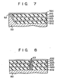
- Fig. 3 is a sectional view of a stacked semiconductor device of a simplest structure among Figs. 3, 5, 7 and 8.
- reference numeral 30 denotes a monocrystalline semiconductor substrate.
- Reference numerals 31a, 31 b and 31c respectively denote first, second and third insulating films; 32a, 32b and 32c, respectively first, second and third monocrystalline semiconductor films; and 33, a connecting region for connecting the semiconductor substrate 30, the first monocrystalline semiconductor film 32a, the second monocrystalline semiconductor film 32b, and the third monocrystalline semiconductor film 32c.
- the connecting region 33 is used as a seed crystal portion when the monocrystalline semiconductor films 32a to 32c are formed.
- the first, second and third monocrystalline semiconductor films 32a, 32b and 32c are coupled to the semiconductor substrate 30 at the connecting region 33. Conversion into single crystals is performed by using the semiconductor substrate 30 or a monocrystalline semiconductor film portion which has a highly quality and which is closest to the semiconductor substrate 30 as the seed crystal. Therefore, the monocrystalline semiconductor films can be easily formed and have high quality.
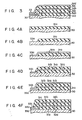
- Figs. 4A to 4F are sectional views for explaining the manufacture, according to the invention, of the stacked semiconductor device shown in Fig. 3.
- the monocrystalline semiconductor substrate 30 comprises silicon.
- the first insulating film 31a which comprises an Si0 2 film is formed thereon.
- part of the first insulating film 31a is etched to expose part of the semiconductor substrate as a first connecting region 33a.
- a polycrystalline or amorphous semiconductor film of the same material as that of the semiconductor substrate is deposited to cover the entire surface. Annealing is performed using the first connecting region 33a as the seed crystal.
- an element or circuit is formed on the first monocrystalline silicon film 32a.
- Fig. 4A the first insulating film 31a which comprises an Si0 2 film is formed thereon.
- part of the first insulating film 31a is etched to expose part of the semiconductor substrate as a first connecting region 33a.
- a polycrystalline or amorphous semiconductor film of the same material as that of the semiconductor substrate is deposited to cover the entire surface. Annealing is performed using the first connecting region 33a as the seed crystal.
- an element or circuit is formed on the first monocrystalline silicon film 32a.
- the second insulating film 31 b is deposited to cover the first semiconductor film 32a, and a portion of the film 31b immediately on the first connecting region 33a is removed. An exposed portion of the film 32a is defined as a second connecting region 33b.
- a polycrystalline or amorphous semiconductor film is deposited and converted to a monocrystalline semiconductor film using the second connecting region 33b as the seed crystal.
- the second monocrystalline semiconductor film 32b is obtained.
- the third insulating film 31c is deposited on the second semiconductor film 32b as shown in Fig. 4F.
- a portion of the second semiconductor film 32b immediately on the second connecting region 33b is exposed to form a third connecting region 33c.
- monocrystalline semiconductor films are formed.
- Example 1 if the connecting region 33 (33a, 33b, 33c) is formed around the IC chip, the region can be used as a scribing line since this portion is thin.
- Fig. 5 is a sectional view of another semiconductor device.
- reference numeral 40 denotes a semiconductor substrate; 41a, 41 band 41c, first, second and third insulating films, respectively; 42a, 42b and 42c, first, second and third monocrystalline semiconductor films, respectively; and 43, a connecting region.
- the connecting region 43 is a projection which is part of a semiconductor substrate 40.
- the first, second and third monocrystalline semiconductor films 42a, 42b and 42c are formed using the connecting region 43 as a seed crystal. Therefore, the first, second and third monocrystalline semiconductor films 42a, 42b and 42c are directly in contact with the side surface of the connecting region 43.
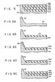
- Figs. 6A to 6E are sectional views for explaining the steps of manufacturing, according to the invention, the stacked integrated circuit shown in Fig. 5.
- the monocrystalline semiconductor substrate 40 is etched deeply to leave the connecting region 43.
- a desired element or circuit is formed in a recess of the substrate.
- the first insulating film 41a is selectively deposited.
- a polycrystalline or amorphous semiconductor film is deposited to cover the entire surface. Annealing is performed starting from the portion of the polycrystalline or amorphous semiconductor film which contacts the connecting region 43, so that conversion into single crystal advances to form a monocrystalline semiconductor film.
- a portion of the monocrystalline semiconductor film is etched except for the flat portion thereof, so that the connecting region 43 is exposed.
- the first monocrystalline semiconductor film 42a is obtained.
- the second insulating film 41 b is selectively formed in the recess of the substrate, as shown in Fig. 6E.
- a stacked semiconductor integrated circuit is prepared.
- the height of the connecting region 43 and the depth of the recess of the substrate are preferably determined so as to obtain a flat surface as shown in Fig. 5 when the stacked semiconductor device is obtained.
- the position of the connecting region 43 may be in the periphery of the integrated circuit chip.
- the connecting region 43 since the structure provides a flat surface, it is convenient to use the connecting region 43 as part of the circuit (e.g., common ground line or a power source line required for the multi-layer).
- Several connecting regions similar to the connecting region 43 can be formed in the IC chip as needed. In this case, the range of conversion into single crystals to be controlled by a single connecting region is narrow, a high yield of conversion into single crystals is achieved, and a highly reliable and high-performance semiconductor device can be obtained as a whole.
- FIG. 7 Portions overlaid on the connecting region 43 are etched every time in this embodiment. However, if these portions are left, a structure as shown in Fig. 7 can be obtained. Thus structure is a combination of the structures shown in Figs. 3 and 5.
- reference numeral 50 denotes a monocrystalline semiconductor substrate; and 51a, 51b and 51c, first, second and third insulating films, respectively; and 52a, 52b and 52c, first, second and third monocrystalline semiconductor films.
- a connecting region 53 is formed on the projection of the semiconductor substrate 50.
- Fig. 8 is a sectional view of another stacked semiconductor device.
- reference numeral 60 denotes a monocrystalline semiconductor substrate; 61a, 61b and 61c, first, second and third insulating films, respectively; 62a, 62b and 62c, first, second and third monocrystalline semiconductor films, respectively; and 63, connecting regions which comprise a monocrystalline semiconductor.
- the connecting regions 63 are made of the same semiconductor material as that of the semiconductor substrate 60.
- the connecting regions 63 are used as the seed crystal for conversion into single crystals to form the first to third monocrystalline semiconductor films 62a to 62c.
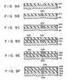
- Figs. 9A to 9F are sectional views for explaining the steps of manufacturing according to the invention, the stacked semiconductor device shown in Fig. 8.
- the first insulating film 61 a is formed thereon except for a prospective connecting region.
- a first connecting region 63a which of the same material as that of the semiconductor substrate 60 is selectively grown as a seed crystal by the epitaxial growth method. Part of the semiconductor substrate 60 is virtually projected to a height corresponding to one cycle of layer formation. The upper surface of the grown layer is at the same level as that of the first insulating film 61a.
- a polycrystalline or amorphous semiconductor layer is deposited to cover the entire surface.
- Annealing is performed starting from the point where the polycrystalline or amorphous semiconductor film contacts the first connecting region 63a.
- the polycrystalline or amorphous semiconductor film is converted to a monocrystalline silicon film using the first connecting region 63a as the seed crystal.
- the first monocrystalline semiconductor film 62a is obtained.
- a desired element or circuit is formed on the first monocrystalline semiconductor film 62a.
- the second insulating film 61b is selectively deposited on the first monocrystalline semiconductor film 62a except for a portion immediately on the connecting region 63a.
- a second connecting region 63b which is of the same semiconductor material as that of the semiconductor substrate 60 is selectively formed by the epitaxial growth method.
- the upper surface of the grown film is at the same level as that of the second insulating film 61 b.
- a polycrystalline or amorphous semiconductor film is deposited, and annealing is performed starting from a point where the polycrystalline or amorphous semiconductor film contacts the connecting region, so that the polycrystalline or amorphous semiconductor film is converted to a monocrystalline semiconductor film using the second connecting region 63b as a seed crystal.
- the second monocrystalline semiconductor film 62b is obtained.
- Example 3 selective epitaxial growth is performed to form every connection region.
- the connecting regions are vertically connected from the semiconductor substrate to the layers formed thereon.
- the same effect as obtained in Example 1 and 2 can be obtained in Example 3.
- a monocrystalline semiconductor film of high quality is produced with a high yield.
- the surface of each layer is made flat, and the connecting regions can be used as the common ground line or power source line.
- each monocrystalline semiconductor layer may be formed relatively thick, and then selectively etched to leave a connecting region.
Description
- The present invention relates to a method of manufacturing a stacked semiconductor device which comprises a plurality of stacked monocrystalline semiconductor films each of which has a plurality of semiconductor elements.
- Such a stacked semiconductor device wherein the plurality of stacked monocrystalline semiconductor films of the same material between which insulating layers are sandwiched is very promising as a photo semiconductor device and as a three-dimensional integrated circuit.
- Fig. 1 is a sectional view of a stacked semiconductor device proposed by the applicant. Referring to Fig. 1,
reference numeral 10 denotes a monocrystalline semiconductor substrate; and 11a, 11b and 11c, first, second and third monocrystalline semiconductor films.Reference numerals semiconductor substrate 10 and the first semiconductor film 11a, between the first and secondmonocrystalline semiconductor films 11a and 11b, and between the second and thirdmonocrystalline semiconductor films 11 b and 11c.Reference numerals semiconductor substrate 10 and the first monocrystalline semiconductor film 11a, between the first and secondmonocrystalline semiconductor films 11a and 11b, between the second and thirdmonocrystalline semiconductor films 11b and 11c.Reference numerals 14a, 14b and 14c denote first, second and third isolating layers respectively formed in the first, second and third monocrystalline semiconductor films. - Figs. 2A to 2E are sectional views for explaining the steps of manufacturing the stacked semiconductor device shown in Fig. 1. The semiconductor elements formed in the monocrystalline semiconductor substrate and the monocrystalline semiconductor films throughout Figs. 1 to 9F are not directly related to the present invention, so that the description and illustration thereof will be omitted for descriptive convenience.
- Referring to Fig. 2A, the first insulating film 12a is deposited on the
semiconductor substrate 10 except for theconnecting region 13a. As shown in Fig. 2B, a polycrystalline or amorphous semiconductor film is deposited on the first insulating film 12a. Thereafter, annealing such as laser annealing is performed to grow single crystals using the connectingregion 13a as a seed crystal. As a result, the first monocrystalline semiconductor film 11 a is formed. - As shown in Fig. 2C, the second
insulating film 12b is then deposited on the first monocrystalline semiconductor film 11a a except for theconnecting region 13b. As shown in Fig. 2D, a polycrystalline or amorphous semiconductor film is deposited to cover the entire surface. Thus, in the same manner as the first monocrystalline semiconductor film 11a, the secondmonocrystalline semiconductor film 11b b is obtained. Similarly, as shown in Fig. 2E, the third insulating film 12C is deposited on the second monocrystalline semi-conductorfilm 11b except for the third connecting region 13c. The third monocrystalline semiconductor film 11c is then formed to obtain the structure shown in Fig. 1. - This technique is disclosed in EP-A-0073487, relevant under article 54(3).
- In the described method for manufacturing the stacked semiconductor device and the thus obtained semiconductor device, the following drawbacks are presented. It is important to convert the polycrystalline or amorphous semiconductor film to a monocrystalline semiconductor film using part of the semiconductor substrate or part of the underlying monocrystalline semiconductor film as a seed crystal. However, since the polycrystalline or amorphous semiconductor film is formed on the insulating layer, the above conversion is difficult to accomplish at a location which is apart from the seed crystal. In the conventional stacked semiconductor device, the position of the seed crystal has been arbitrarily selected in accordance with the element or circuit configuration. For this reason, the first, second and third connecting
regions monocrystalline semiconductor films 11a, 11b and 11c are greatly spaced apart from each other. When the number of monocrystalline semiconductor films to be stacked is increased, the distance for conversion into single crystals from the semiconductor substrate is increased which is regarded as the initial seed crystal. Therefore, conversion into single crystals can hardly be achieved. In this condition, almost impossible control conditions of annealing or the like are required for conversion into single crystals. Furthermore, even if the stacked monocrystalline semiconductor structure is obtained by the above process, the crystal quality of the upper semiconductor films is greatly degraded. For example, the carrier mobility is greatly degraded. - DE-A-1 598705 discloses a stacked semiconductor device having a plurality of monocrystalline silicon films which are formed on a monocrystalline semiconductor substrate and between which insulating films are sandwiched. The insulating films are formed with channels filled with monocrystalline silicon thereby providing a connecting region by means of which the monocrystalline semiconductor films are connected.
- It is, therefore, an object of the present invention to provide a method of stacked semiconductor device which has a plurality of stacked semiconductor films of high quality on a semiconductor substrate.
- According to the present invention, there is provided a method for manufacturing a stacked semiconductor device, comprising:
- forming a first non-monocrystalline semiconductor film on a monocrystalline semiconductor substrate with an intervening first insulating film;
- converting said first non-monocrystalline semiconductor film into a first monocrystalline semiconductor film;
- forming a second non-monocrystalline semiconductor film on said first monocrystalline semiconductor film with an intervening second insulating film; and
- converting said second non-monocrystalline semiconductor film into a second monocrystalline film, wherein the conversion into the monocrystalline semiconductor film is performed by using as a seed crystal at least one connecting region at which said semiconductor substrate and said first and second monocrystalline semiconductor films are vertically connected.
- This invention can be more fully understood from the following detailed description when taken in conjunction with the accompanying drawings, in which:-
- Fig. 1 is a sectional view of a proposed stacked semiconductor device;
- Figs. 2A to 2E are sectional views for explaining the steps of manufacturing the stacked semiconductor device shown in Fig. 1;
- Fig. 3 is a sectional view of a stacked semiconductor device;
- Figs. 4A to 4F are sectional views for explaining the steps of manufacturing the stacked semiconductor device shown in Fig. 3;
- Fig. 5 is a sectional view of a stacked semiconductor device;
- Figs. 6a to 6E are sectional views for explaining the steps of manufacturing the stacked semiconductor device shown in Fig. 5;
- Fig. 7 is a sectional view of a stacked semiconductor device;
- Fig. 8 is a sectional view of a stacked semiconductor device; and
- Figs. 9A to 9F are sectional views for explaining the steps of manufacturing the semiconductor device shown in Fig. 8.
- In a stacked semiconductor device manufacture by a method according to the present invention, a plurality of monocrystalline semiconductor films are stacked on a semiconductor substrate and sandwich insulating films therebetween. The semiconductor substrate comprises, for example, an n-type or p-type semiconductor substrate, or such a semiconductor substrate or sapphire substrate on which a single-crystalline semiconductor layer is formed. The monocrystalline semiconductor films between which the insulating films are sandwiched are vertically connected at a connecting region. The connecting region may be used as a seed crystal for forming monocrystalline semiconductor films. Each monocrystalline semiconductor film is formed such that a polycrystalline or amorphous semiconductor film is deposited on the insulating film and annealing is then performed by means of a laser or electron beam using the connecting region as the seed crystal.
- The number of the connecting regions need not be limited to one, but a plurality of connecting regions may be formed. In this case, all the monocrystalline semiconductor films need not be formed using the same connecting region as the seed crystal. A given semiconductor film may be formed to be a monocrystalline silicon film using a given connecting region as the seed crystal. Similarly, another given semiconductor film may be formed to be a monocrystalline silicon film using another given connecting region as the seed crystal.
- Since conversion into single crystals can be performed using as the seed crystal part of the semiconductor substrate or any given single crystal which is adjacent thereto, a monocrystalline semiconductor film with high quality can be obtained. Therefore, the carrier mobility is not greatly degraded, thus providing a high-speed stacked semiconductor device.
- Examples of the present invention will be described in detail.
- Fig. 3 is a sectional view of a stacked semiconductor device of a simplest structure among Figs. 3, 5, 7 and 8. Referring to Fig. 3,
reference numeral 30 denotes a monocrystalline semiconductor substrate.Reference numerals semiconductor substrate 30, the first monocrystalline semiconductor film 32a, the secondmonocrystalline semiconductor film 32b, and the third monocrystalline semiconductor film 32c. The connectingregion 33 is used as a seed crystal portion when the monocrystalline semiconductor films 32a to 32c are formed. According to the stacked semiconductor device of the above structure, the first, second and thirdmonocrystalline semiconductor films 32a, 32b and 32c are coupled to thesemiconductor substrate 30 at the connectingregion 33. Conversion into single crystals is performed by using thesemiconductor substrate 30 or a monocrystalline semiconductor film portion which has a highly quality and which is closest to thesemiconductor substrate 30 as the seed crystal. Therefore, the monocrystalline semiconductor films can be easily formed and have high quality. - Figs. 4A to 4F are sectional views for explaining the manufacture, according to the invention, of the stacked semiconductor device shown in Fig. 3.
- Referring to Fig. 4A, the
monocrystalline semiconductor substrate 30 comprises silicon. After a desired element or circuit is formed on the substrate, the first insulatingfilm 31a which comprises an Si02 film is formed thereon. As shown in Fig. 4B, part of the first insulatingfilm 31a is etched to expose part of the semiconductor substrate as a first connectingregion 33a. As shown in Fig. 4C, a polycrystalline or amorphous semiconductor film of the same material as that of the semiconductor substrate is deposited to cover the entire surface. Annealing is performed using the first connectingregion 33a as the seed crystal. Thus, the first monocrystalline semiconductor film 32a is obtained. Thereafter, an element or circuit is formed on the first monocrystalline silicon film 32a. As shown in Fig. 4D, the second insulatingfilm 31 b is deposited to cover the first semiconductor film 32a, and a portion of thefilm 31b immediately on the first connectingregion 33a is removed. An exposed portion of the film 32a is defined as a second connectingregion 33b. As shown in Fig. 4E, a polycrystalline or amorphous semiconductor film is deposited and converted to a monocrystalline semiconductor film using the second connectingregion 33b as the seed crystal. Thus, the secondmonocrystalline semiconductor film 32b is obtained. After an element or circuit is formed on the secondmonocrystalline semiconductor film 32b, the thirdinsulating film 31c is deposited on thesecond semiconductor film 32b as shown in Fig. 4F. At the same time, a portion of thesecond semiconductor film 32b immediately on the second connectingregion 33b is exposed to form a third connecting region 33c. In the same manner as described above, monocrystalline semiconductor films are formed. - In Example 1, if the connecting region 33 (33a, 33b, 33c) is formed around the IC chip, the region can be used as a scribing line since this portion is thin.
- Fig. 5 is a sectional view of another semiconductor device. Referring to Fig. 5,
reference numeral 40 denotes a semiconductor substrate; 41a, 41 band 41c, first, second and third insulating films, respectively; 42a, 42b and 42c, first, second and third monocrystalline semiconductor films, respectively; and 43, a connecting region. In Example 2, the connectingregion 43 is a projection which is part of asemiconductor substrate 40. The first, second and thirdmonocrystalline semiconductor films 42a, 42b and 42c are formed using the connectingregion 43 as a seed crystal. Therefore, the first, second and thirdmonocrystalline semiconductor films 42a, 42b and 42c are directly in contact with the side surface of the connectingregion 43. - Figs. 6A to 6E are sectional views for explaining the steps of manufacturing, according to the invention, the stacked integrated circuit shown in Fig. 5.
- As shown in Fig. 6A, the
monocrystalline semiconductor substrate 40 is etched deeply to leave the connectingregion 43. A desired element or circuit is formed in a recess of the substrate. As shown in Fig. 6B, the first insulating film 41a is selectively deposited. Subsequently, as shown in Fig. 6C, a polycrystalline or amorphous semiconductor film is deposited to cover the entire surface. Annealing is performed starting from the portion of the polycrystalline or amorphous semiconductor film which contacts the connectingregion 43, so that conversion into single crystal advances to form a monocrystalline semiconductor film. As shown in Fig. 6D, a portion of the monocrystalline semiconductor film is etched except for the flat portion thereof, so that the connectingregion 43 is exposed. Thus, the first monocrystalline semiconductor film 42a is obtained. After a desired element or circuit is formed, the second insulatingfilm 41 b is selectively formed in the recess of the substrate, as shown in Fig. 6E. By repeating the process described above, a stacked semiconductor integrated circuit is prepared. - The height of the connecting
region 43 and the depth of the recess of the substrate are preferably determined so as to obtain a flat surface as shown in Fig. 5 when the stacked semiconductor device is obtained. The position of the connectingregion 43 may be in the periphery of the integrated circuit chip. Furthermore, since the structure provides a flat surface, it is convenient to use the connectingregion 43 as part of the circuit (e.g., common ground line or a power source line required for the multi-layer). Several connecting regions similar to the connectingregion 43 can be formed in the IC chip as needed. In this case, the range of conversion into single crystals to be controlled by a single connecting region is narrow, a high yield of conversion into single crystals is achieved, and a highly reliable and high-performance semiconductor device can be obtained as a whole. - Portions overlaid on the connecting
region 43 are etched every time in this embodiment. However, if these portions are left, a structure as shown in Fig. 7 can be obtained. Thus structure is a combination of the structures shown in Figs. 3 and 5. Referring to Fig. 7,reference numeral 50 denotes a monocrystalline semiconductor substrate; and 51a, 51b and 51c, first, second and third insulating films, respectively; and 52a, 52b and 52c, first, second and third monocrystalline semiconductor films. A connectingregion 53 is formed on the projection of thesemiconductor substrate 50. - Fig. 8 is a sectional view of another stacked semiconductor device. Referring to Fig. 8,
reference numeral 60 denotes a monocrystalline semiconductor substrate; 61a, 61b and 61c, first, second and third insulating films, respectively; 62a, 62b and 62c, first, second and third monocrystalline semiconductor films, respectively; and 63, connecting regions which comprise a monocrystalline semiconductor. The connectingregions 63 are made of the same semiconductor material as that of thesemiconductor substrate 60. The connectingregions 63 are used as the seed crystal for conversion into single crystals to form the first to third monocrystalline semiconductor films 62a to 62c. - Figs. 9A to 9F are sectional views for explaining the steps of manufacturing according to the invention, the stacked semiconductor device shown in Fig. 8.
- As shown in Fig. 9A, after an desired element or circuit is formed on the
monocrystalline semiconductor substrate 60, the first insulatingfilm 61 a is formed thereon except for a prospective connecting region. As shown in Fig. 9B, a first connectingregion 63a which of the same material as that of thesemiconductor substrate 60 is selectively grown as a seed crystal by the epitaxial growth method. Part of thesemiconductor substrate 60 is virtually projected to a height corresponding to one cycle of layer formation. The upper surface of the grown layer is at the same level as that of the first insulatingfilm 61a. As shown in Fig. 9c, a polycrystalline or amorphous semiconductor layer is deposited to cover the entire surface. Annealing is performed starting from the point where the polycrystalline or amorphous semiconductor film contacts the first connectingregion 63a. The polycrystalline or amorphous semiconductor film is converted to a monocrystalline silicon film using the first connectingregion 63a as the seed crystal. Thus, the first monocrystalline semiconductor film 62a is obtained. A desired element or circuit is formed on the first monocrystalline semiconductor film 62a. As shown in Fig. 9D, the second insulating film 61b is selectively deposited on the first monocrystalline semiconductor film 62a except for a portion immediately on the connectingregion 63a. As shown in Fig. 9E, a second connectingregion 63b which is of the same semiconductor material as that of thesemiconductor substrate 60 is selectively formed by the epitaxial growth method. At this time, the upper surface of the grown film is at the same level as that of the second insulating film 61 b. As shown in Fig. 9F, a polycrystalline or amorphous semiconductor film is deposited, and annealing is performed starting from a point where the polycrystalline or amorphous semiconductor film contacts the connecting region, so that the polycrystalline or amorphous semiconductor film is converted to a monocrystalline semiconductor film using the second connectingregion 63b as a seed crystal. Thus, the secondmonocrystalline semiconductor film 62b is obtained. By repeating the same process as described above, a stacked semiconductor device is prepared. - In Example 3, selective epitaxial growth is performed to form every connection region. In this case, the connecting regions are vertically connected from the semiconductor substrate to the layers formed thereon. The same effect as obtained in Example 1 and 2 can be obtained in Example 3. A monocrystalline semiconductor film of high quality is produced with a high yield. Furthermore, the surface of each layer is made flat, and the connecting regions can be used as the common ground line or power source line.
- According to Example 3, the connecting region is formed by the epitaxial growth method. However, each monocrystalline semiconductor layer may be formed relatively thick, and then selectively etched to leave a connecting region.
Claims (11)
Applications Claiming Priority (2)
| Application Number | Priority Date | Filing Date | Title |
|---|---|---|---|
| JP151484/81 | 1981-09-25 | ||
| JP56151484A JPS5853822A (en) | 1981-09-25 | 1981-09-25 | Laminated semiconductor device |
Publications (3)
| Publication Number | Publication Date |
|---|---|
| EP0076101A2 EP0076101A2 (en) | 1983-04-06 |
| EP0076101A3 EP0076101A3 (en) | 1984-09-05 |
| EP0076101B1 true EP0076101B1 (en) | 1987-09-16 |
Family
ID=15519506
Family Applications (1)
| Application Number | Title | Priority Date | Filing Date |
|---|---|---|---|
| EP82305016A Expired EP0076101B1 (en) | 1981-09-25 | 1982-09-23 | Methode of manufacturing a stacked semiconductor device |
Country Status (4)
| Country | Link |
|---|---|
| US (1) | US4569700A (en) |
| EP (1) | EP0076101B1 (en) |
| JP (1) | JPS5853822A (en) |
| DE (1) | DE3277346D1 (en) |
Families Citing this family (19)
| Publication number | Priority date | Publication date | Assignee | Title |
|---|---|---|---|---|
| JPS5610782A (en) * | 1979-07-06 | 1981-02-03 | Nippon Texas Instr Kk | Demodulating circuit for sound multiplex broadcast |
| JPS5890763A (en) * | 1981-11-25 | 1983-05-30 | Mitsubishi Electric Corp | Semiconductor device |
| JPS5892257A (en) * | 1981-11-27 | 1983-06-01 | Mitsubishi Electric Corp | Semiconductor device |
| JPS6014462A (en) * | 1983-07-05 | 1985-01-25 | Oki Electric Ind Co Ltd | Semiconductor memory element |
| JPS60189217A (en) * | 1984-03-09 | 1985-09-26 | Agency Of Ind Science & Technol | Seed construction for multilayer soi |
| JPS61121433A (en) * | 1984-11-19 | 1986-06-09 | Sharp Corp | Semiconductor substrate |
| US4663831A (en) * | 1985-10-08 | 1987-05-12 | Motorola, Inc. | Method of forming transistors with poly-sidewall contacts utilizing deposition of polycrystalline and insulating layers combined with selective etching and oxidation of said layers |
| KR900008647B1 (en) * | 1986-03-20 | 1990-11-26 | 후지쓰 가부시끼가이샤 | A method for manufacturing three demensional i.c. |
| EP0251767A3 (en) * | 1986-06-30 | 1988-09-07 | Canon Kabushiki Kaisha | Insulated gate type semiconductor device and method of producing the same |
| JPH0812906B2 (en) * | 1986-07-11 | 1996-02-07 | キヤノン株式会社 | Method for manufacturing photoelectric conversion device |
| US5045501A (en) * | 1986-08-25 | 1991-09-03 | Hughes Aircraft Company | Method of forming an integrated circuit structure with multiple common planes |
| US4849371A (en) * | 1986-12-22 | 1989-07-18 | Motorola Inc. | Monocrystalline semiconductor buried layers for electrical contacts to semiconductor devices |
| JPS6457836A (en) * | 1987-08-27 | 1989-03-06 | Fuotonikusu Kk | Receiver |
| JPH02101767A (en) * | 1988-10-11 | 1990-04-13 | Agency Of Ind Science & Technol | Semiconductor device |
| US5191405A (en) * | 1988-12-23 | 1993-03-02 | Matsushita Electric Industrial Co., Ltd. | Three-dimensional stacked lsi |
| FR2645681B1 (en) * | 1989-04-07 | 1994-04-08 | Thomson Csf | DEVICE FOR VERTICALLY INTERCONNECTING PADS OF INTEGRATED CIRCUITS AND ITS MANUFACTURING METHOD |
| DE4417916A1 (en) * | 1994-05-24 | 1995-11-30 | Telefunken Microelectron | Method of manufacturing a bipolar transistor |
| US20060113596A1 (en) * | 2004-12-01 | 2006-06-01 | Samsung Electronics Co., Ltd. | Single crystal substrate and method of fabricating the same |
| US7776718B2 (en) * | 2007-06-25 | 2010-08-17 | Semiconductor Energy Laboratory Co., Ltd. | Method of manufacturing semiconductor substrate with reduced gap size between single-crystalline layers |
Citations (1)
| Publication number | Priority date | Publication date | Assignee | Title |
|---|---|---|---|---|
| EP0073487A2 (en) * | 1981-08-31 | 1983-03-09 | Kabushiki Kaisha Toshiba | Method for manufacturing three-dimensional semiconductor device |
Family Cites Families (11)
| Publication number | Priority date | Publication date | Assignee | Title |
|---|---|---|---|---|
| FR1417088A (en) * | 1963-12-16 | 1965-11-05 | Rca Corp | Insulating and semiconducting composite pellets |
| DE1589705A1 (en) * | 1967-11-15 | 1970-04-30 | Itt Ind Gmbh Deutsche | Integrated circuit containing multiple electrical functional levels |
| DE2832012A1 (en) * | 1978-07-20 | 1980-01-31 | Siemens Ag | Three=dimensional integrated circuit prodn. - has epitaxially grown substrate with components produced by alternate doping |
| NL7810549A (en) * | 1978-10-23 | 1980-04-25 | Philips Nv | METHOD FOR MANUFACTURING A SEMICONDUCTOR DEVICE |
| EP0020135A1 (en) * | 1979-05-29 | 1980-12-10 | Massachusetts Institute Of Technology | Three-dimensional integration by graphoepitaxy |
| JPS5667923A (en) * | 1979-11-07 | 1981-06-08 | Toshiba Corp | Preparation method of semiconductor system |
| US4323417A (en) * | 1980-05-06 | 1982-04-06 | Texas Instruments Incorporated | Method of producing monocrystal on insulator |
| US4319954A (en) * | 1981-02-27 | 1982-03-16 | Rca Corporation | Method of forming polycrystalline silicon lines and vias on a silicon substrate |
| JPS57155764A (en) * | 1981-03-20 | 1982-09-25 | Fujitsu Ltd | Manufacture of semiconductor device |
| JPS5861622A (en) * | 1981-10-09 | 1983-04-12 | Hitachi Ltd | Manufacture of single crystal thin film |
| JPS59108313A (en) * | 1982-12-13 | 1984-06-22 | Mitsubishi Electric Corp | Manufacture of semiconductor single crystal layer |
-
1981
- 1981-09-25 JP JP56151484A patent/JPS5853822A/en active Pending
-
1982
- 1982-09-23 DE DE8282305016T patent/DE3277346D1/en not_active Expired
- 1982-09-23 EP EP82305016A patent/EP0076101B1/en not_active Expired
-
1985
- 1985-07-01 US US06/750,245 patent/US4569700A/en not_active Expired - Lifetime
Patent Citations (1)
| Publication number | Priority date | Publication date | Assignee | Title |
|---|---|---|---|---|
| EP0073487A2 (en) * | 1981-08-31 | 1983-03-09 | Kabushiki Kaisha Toshiba | Method for manufacturing three-dimensional semiconductor device |
Also Published As
| Publication number | Publication date |
|---|---|
| JPS5853822A (en) | 1983-03-30 |
| EP0076101A3 (en) | 1984-09-05 |
| EP0076101A2 (en) | 1983-04-06 |
| DE3277346D1 (en) | 1987-10-22 |
| US4569700A (en) | 1986-02-11 |
Similar Documents
| Publication | Publication Date | Title |
|---|---|---|
| EP0076101B1 (en) | Methode of manufacturing a stacked semiconductor device | |
| EP0073487B1 (en) | Method for manufacturing three-dimensional semiconductor device | |
| US4948456A (en) | Confined lateral selective epitaxial growth | |
| US4472729A (en) | Recrystallized three dimensional integrated circuit | |
| JPH02110968A (en) | Semiconductor element and its manufacture and multilayer semiconductor device | |
| JP2505754B2 (en) | Method for manufacturing photoelectric conversion device | |
| US3624467A (en) | Monolithic integrated-circuit structure and method of fabrication | |
| US4685199A (en) | Method for forming dielectrically isolated PMOS, NMOS, PNP and NPN transistors on a silicon wafer | |
| JPH02306680A (en) | Optoelectronic integrated circuit device and manufacture thereof | |
| KR100353174B1 (en) | Method for fabrication of silicon on insulator substrates | |
| EP0036764B1 (en) | A semiconductor device with a v-groove insulating isolation structure and a method of manufacturing such a device | |
| US3738883A (en) | Dielectric isolation processes | |
| EP0343738A2 (en) | Manufacture of electronic devices comprising cadmium mercury telluride with silicon-on-sapphire circuitry | |
| JPS6393174A (en) | Photodiode | |
| US3797102A (en) | Method of making semiconductor devices | |
| JPS60144949A (en) | Manufacture of semiconductor device | |
| JPH0233918A (en) | Manufacture of three-dimensional device | |
| JPS5890740A (en) | Semiconductor device | |
| JPS60101945A (en) | Manufacture of semiconductor device | |
| JP3043370B2 (en) | Manufacturing method of dielectric isolation substrate | |
| JPH01290235A (en) | Semiconductor integrated circuit device | |
| JPS59186341A (en) | Manufacture of complementary dielectric isolation substrate | |
| EP0227523A2 (en) | Method for obtaining regions of dielectrically isolated single crystal silicon | |
| JPS61290709A (en) | Manufacture of semiconductor device | |
| JPS61171148A (en) | Manufacture of semiconductor device material |
Legal Events
| Date | Code | Title | Description |
|---|---|---|---|
| PUAI | Public reference made under article 153(3) epc to a published international application that has entered the european phase |
Free format text: ORIGINAL CODE: 0009012 |
|
| 17P | Request for examination filed |
Effective date: 19821001 |
|
| AK | Designated contracting states |
Designated state(s): DE FR GB IT |
|
| PUAL | Search report despatched |
Free format text: ORIGINAL CODE: 0009013 |
|
| AK | Designated contracting states |
Designated state(s): DE FR GB IT |
|
| RAP1 | Party data changed (applicant data changed or rights of an application transferred) |
Owner name: KABUSHIKI KAISHA TOSHIBA |
|
| GRAA | (expected) grant |
Free format text: ORIGINAL CODE: 0009210 |
|
| AK | Designated contracting states |
Kind code of ref document: B1 Designated state(s): DE FR GB |
|
| ET | Fr: translation filed | ||
| REF | Corresponds to: |
Ref document number: 3277346 Country of ref document: DE Date of ref document: 19871022 |
|
| PLBE | No opposition filed within time limit |
Free format text: ORIGINAL CODE: 0009261 |
|
| STAA | Information on the status of an ep patent application or granted ep patent |
Free format text: STATUS: NO OPPOSITION FILED WITHIN TIME LIMIT |
|
| 26N | No opposition filed | ||
| PGFP | Annual fee paid to national office [announced via postgrant information from national office to epo] |
Ref country code: DE Payment date: 19960927 Year of fee payment: 15 |
|
| PGFP | Annual fee paid to national office [announced via postgrant information from national office to epo] |
Ref country code: FR Payment date: 19970909 Year of fee payment: 16 |
|
| PGFP | Annual fee paid to national office [announced via postgrant information from national office to epo] |
Ref country code: GB Payment date: 19970915 Year of fee payment: 16 |
|
| PG25 | Lapsed in a contracting state [announced via postgrant information from national office to epo] |
Ref country code: DE Free format text: LAPSE BECAUSE OF NON-PAYMENT OF DUE FEES Effective date: 19980603 |
|
| PG25 | Lapsed in a contracting state [announced via postgrant information from national office to epo] |
Ref country code: GB Free format text: LAPSE BECAUSE OF NON-PAYMENT OF DUE FEES Effective date: 19980923 |
|
| GBPC | Gb: european patent ceased through non-payment of renewal fee |
Effective date: 19980923 |
|
| PG25 | Lapsed in a contracting state [announced via postgrant information from national office to epo] |
Ref country code: FR Free format text: LAPSE BECAUSE OF NON-PAYMENT OF DUE FEES Effective date: 19990531 |
|
| REG | Reference to a national code |
Ref country code: FR Ref legal event code: ST |