EP0075196A1 - Position control of the drilling spindle of a radial drilling machine - Google Patents
Position control of the drilling spindle of a radial drilling machine Download PDFInfo
- Publication number
- EP0075196A1 EP0075196A1 EP82108276A EP82108276A EP0075196A1 EP 0075196 A1 EP0075196 A1 EP 0075196A1 EP 82108276 A EP82108276 A EP 82108276A EP 82108276 A EP82108276 A EP 82108276A EP 0075196 A1 EP0075196 A1 EP 0075196A1
- Authority
- EP
- European Patent Office
- Prior art keywords
- workpiece
- machine
- drilling
- coordinate system
- circuit
- Prior art date
- Legal status (The legal status is an assumption and is not a legal conclusion. Google has not performed a legal analysis and makes no representation as to the accuracy of the status listed.)
- Granted
Links
Images


Classifications
-
- G—PHYSICS
- G05—CONTROLLING; REGULATING
- G05B—CONTROL OR REGULATING SYSTEMS IN GENERAL; FUNCTIONAL ELEMENTS OF SUCH SYSTEMS; MONITORING OR TESTING ARRANGEMENTS FOR SUCH SYSTEMS OR ELEMENTS
- G05B19/00—Programme-control systems
- G05B19/02—Programme-control systems electric
- G05B19/18—Numerical control [NC], i.e. automatically operating machines, in particular machine tools, e.g. in a manufacturing environment, so as to execute positioning, movement or co-ordinated operations by means of programme data in numerical form
- G05B19/408—Numerical control [NC], i.e. automatically operating machines, in particular machine tools, e.g. in a manufacturing environment, so as to execute positioning, movement or co-ordinated operations by means of programme data in numerical form characterised by data handling or data format, e.g. reading, buffering or conversion of data
- G05B19/4086—Coordinate conversions; Other special calculations
-
- G—PHYSICS
- G05—CONTROLLING; REGULATING
- G05B—CONTROL OR REGULATING SYSTEMS IN GENERAL; FUNCTIONAL ELEMENTS OF SUCH SYSTEMS; MONITORING OR TESTING ARRANGEMENTS FOR SUCH SYSTEMS OR ELEMENTS
- G05B2219/00—Program-control systems
- G05B2219/30—Nc systems
- G05B2219/33—Director till display
- G05B2219/33263—Conversion, transformation of coordinates, cartesian or polar
-
- G—PHYSICS
- G05—CONTROLLING; REGULATING
- G05B—CONTROL OR REGULATING SYSTEMS IN GENERAL; FUNCTIONAL ELEMENTS OF SUCH SYSTEMS; MONITORING OR TESTING ARRANGEMENTS FOR SUCH SYSTEMS OR ELEMENTS
- G05B2219/00—Program-control systems
- G05B2219/30—Nc systems
- G05B2219/35—Nc in input of data, input till input file format
- G05B2219/35354—Polar coordinates, turntable
-
- G—PHYSICS
- G05—CONTROLLING; REGULATING
- G05B—CONTROL OR REGULATING SYSTEMS IN GENERAL; FUNCTIONAL ELEMENTS OF SUCH SYSTEMS; MONITORING OR TESTING ARRANGEMENTS FOR SUCH SYSTEMS OR ELEMENTS
- G05B2219/00—Program-control systems
- G05B2219/30—Nc systems
- G05B2219/36—Nc in input of data, input key till input tape
- G05B2219/36503—Adapt program to real coordinates, software orientation
-
- Y—GENERAL TAGGING OF NEW TECHNOLOGICAL DEVELOPMENTS; GENERAL TAGGING OF CROSS-SECTIONAL TECHNOLOGIES SPANNING OVER SEVERAL SECTIONS OF THE IPC; TECHNICAL SUBJECTS COVERED BY FORMER USPC CROSS-REFERENCE ART COLLECTIONS [XRACs] AND DIGESTS
- Y10—TECHNICAL SUBJECTS COVERED BY FORMER USPC
- Y10T—TECHNICAL SUBJECTS COVERED BY FORMER US CLASSIFICATION
- Y10T408/00—Cutting by use of rotating axially moving tool
- Y10T408/16—Cutting by use of rotating axially moving tool with control means energized in response to activator stimulated by condition sensor
- Y10T408/175—Cutting by use of rotating axially moving tool with control means energized in response to activator stimulated by condition sensor to control relative positioning of Tool and work
Landscapes
- Engineering & Computer Science (AREA)
- Human Computer Interaction (AREA)
- Manufacturing & Machinery (AREA)
- Physics & Mathematics (AREA)
- General Physics & Mathematics (AREA)
- Automation & Control Theory (AREA)
- Numerical Control (AREA)
- Drilling And Boring (AREA)
- Automatic Control Of Machine Tools (AREA)
- Perforating, Stamping-Out Or Severing By Means Other Than Cutting (AREA)
Abstract
Description
Die Erfindung betrifft ein Verfahren und eine Schaltungsanordnung zur Positionssteuerung einer Radialbohrmaschine.The invention relates to a method and a circuit arrangement for position control of a radial drilling machine.
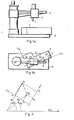
Eine Radialbohrmaschine, auch Auslegerbohrmaschine genannt, weist einen Maschinenkörper auf, der (Fig. 1/a) aus der Grundplatte 6 und einem auf dieser befestigten Ständer besteht, über den die Säule mit dem Ausleger 3 gestülpt ist, der ggf. bis zu 360° verschwenkt werden kann. Entlang des Auslegers 3 ist auf Schienen der Bohrschlitten 2 mit der Bohrspindel 1 verfahrbar.A radial drilling machine, also called boom drilling machine, has a machine body, which (Fig. 1 / a) consists of the
Die Einstellung der Bearbeitungsposition auf Radialbohrmaschinen erfolgt (Fig. 1/b) durch Positionieren der Bohrspindel 1 durch die Bewegung r des Bohrschlittens 2 auf dem Ausleger 5 und durch das Verschwenken a des Auslegers 3, ähnlich wie in einem Polarkoordinatensystem. Dagegen werden die Position und die Toleranz der Mittelpunkte der zu bearbeitenden Bohrungen 5 des Werkstückes 4 auf der Werkzeichnung in kartesischen X- und Y-Koordinaten angegeben. Das Positionieren erfolgt durch Anreißen der einzelnen Werkstücke oder bei größeren Serien mit Hilfe von Vorrichtungen. Die erste Methode ist recht langwierig und ungenau, die zweite außerordentlich kostspielig und aufwendig.The machining position is adjusted on radial drilling machines (FIG. 1 / b) by positioning the drilling spindle 1 by the movement r of the
Zu berücksichtigen ist, daß die Werkstücke, die auf Radialbohrmaschinen gebohrt werden, im allgemeinen groß und sperrig sind und daher nur mühevoll derart auf der Grundplatte der Radialbohrmaschine eingespannt werden können, daß es hinsichtlich des werkstückbezogenen X,Y-Koordinatensystems auch für unterschiedlich gestaltete Werkstücke nach Lage und Ausrichtung stets in auf die Radialbohrmaschine bezogenbestimmter Einspannposition sich befindet.It should be taken into account that the workpieces that are drilled on radial drilling machines are generally large and bulky and can therefore only be clamped with difficulty on the base plate of the radial drilling machine in such a way that the workpiece-related X, Y coordinate system can also be used for differently designed workpieces The position and orientation is always in the clamping position determined in relation to the radial drilling machine.
Durch die Erfindung wird die Aufgabe gelöst, eine Positionssteuerung der Bohrspindel einer Radialbohrmaschine derart zu schaffen, daß die Arbeitspositionen der Bohrspindel in Abhängigkeit von den vorgegebenen X,Y-Koordinaten der Bohrungsmittelpunkte auf dem in die Maschine eingespannten Werkstück unabhängig von dessen Ist-Position und Ist-Ausrichtung in der Maschine steuerbar sind.By the invention the object is achieved to provide a position control of the drilling spindle of a radial drilling machine in such a way that the working positions of the drilling spindle in dependence on the predetermined X, Y coordinates of the drilling centers on the workpiece clamped in the machine regardless of its actual position and actual - Alignment in the machine can be controlled.
Das Verfahren gemäß der Erfindung und die dazu gehörende Schaltungsanordnung basieren auf einer Transformationsverknüpfung zwischen einem maschinenbezogenen Polarkoordinatensystem der Radialbohrmaschine und dem werkstückbezogenen kartesischen Koordinatensystem, auf das die vorgegebenen X,Y-Koordinaten der Mittelpunkte der im Werkstück auszubildenden Bohrungen bezogen sind, in Kenntnis der Relativ-Position der beiden Koordinatensysteme. Durch programmierte Angabe der kartesischen Koordinaten der Werkzeichnung für die Bohrungsmittelpunkte und deren Toleranzen werden die Werte von der Positioniersteuerung ins Koordinatensystem der Radialbohrmaschine transformiert, so daß dadurch das schnelle einfache Positionieren ermöglicht ist. Mit reservierter Transformation können durch die Radialbohrmaschine aufgenommene Koordinaten ins Koordinatensystem des Werkstückes transformiert und als Programm gespeichert werden. Das Verfahren gemäß der Erfindung und die Schaltungsanordnung werden mit Bezugnahme auf die Fig. 1/a, 1/b, 2, 3 und 4 im Folgenden ausführlich beschrieben.The method according to the invention and the associated circuit arrangement are based on a transformation link between a machine-related polar coordinate system of the radial drilling machine and the workpiece-related Cartesian coordinate system, to which the predetermined X, Y coordinates of the center points of the holes to be formed in the workpiece are known, with knowledge of the relative Position of the two coordinate systems. By programming the Cartesian coordinates of the work drawing for the drilling center points and their tolerances, the values are transformed from the positioning control into the coordinate system of the radial drilling machine, so that quick and easy positioning is possible. With reserved transformation, coordinates recorded by the radial drilling machine can be transformed into the coordinate system of the workpiece and saved as a program. The method according to the invention and the circuit arrangement are described in detail below with reference to FIGS. 1 / a, 1 / b, 2, 3 and 4.
Die Bezugszeichen in den Figuren der Zeichnung haben folgende Bedeutung:The reference symbols in the figures of the drawing have the following meaning:
-
Fig. 1
- 1 = Bohrspindel
- 2 = Bohrschlitten
- 3 = Ausleger
- 4 = Werkstück
- 5 = Bohrungen
- 6 = Grundplatte
- P = Bohrspindel-Mittelpunkt
- K = Schwenkachse des Auslegers
- 1 = drilling spindle
- 2 = drilling slide
- 3 = boom
- 4 = workpiece
- 5 = holes
- 6 = base plate
- P = center of drilling spindle
- K = swivel axis of the boom
-
Fig. 2
- K = Schwenkachse des Auslegers, Pol des Polarkoordinatensystems der Radialbohrmaschine R = O
- P = Mittelpunkt der Bohrspindel
- rp = Vom Bohrspindelmittelpunkt beschriebene Gerade während der Bewegung des Bohrschlittens auf dem Ausleger
- rk = Eine die Schwenkachse des Auslegers schneidende und mit rp parallele Gerade
- Kp = senkrechter Abstand zwischen rk und rp
- r = Radiuskoordinate des Polarkoordinatensystems der Radialbohrmaschine
- a = Winkelkoordinate des Polarkoordinatensystems der Radialbohrmaschine
- Rp = Radiuskoordinatenwert des Bohrspindelmittelpunktes
- Ap = Winkelkoordinatenwert des Bohrspindelmittelpunktes
- Pk = Orthogenalprojektion des Bohrspindelmittelpunktes auf die Gerade rk
- R = Radiukoordinatenwert des Punktes Pk
- A = Winklekoordinatenwert des Punktes Pk
- O = Ursprung des kartesischen Koordinatensystems des Werkstücks
- Ro = Radiuskoordinatenwert des Ursprungs
- Ao = Winkelkoordinatenwert des Ursprungs
- Rxy= Länge des vom Ursprung zum Bohrspindelmittelpunkt gerichteten Vektors
- Axy= Winkel des vom Ursprung zum Bohrspindelmittelpunkt gerichteten Vektors zur X-Achse A = Winkel der X-Achse zur Geraden A=0
- x
- x = Ordinate des kartesischen Koordinatensystems des Werkstücks
- y = Abszisse des kartesischen Koordinatensystems des Werkstücks
- X = x-Koordinatenwert des Bohrspindelmittelpunktes
- Y = y-Koordinatenwert des Bohrspindelmittelpunktes
- XRA= Ortlprojektion des vom Ursprung zum Bohrspindelmittelpunkt gerichteten Vektors auf die Gerade A=O
- YRA= Orthogonalprojektion des vom Ursprung zum Bohrspindelmittelpunkt gerichteten Vektors auf die Gerade A=π/2
- K = swivel axis of the boom, pole of the polar coordinate system of the radial drilling machine R = O
- P = center of the drilling spindle
- r p = straight line described by the center of the drilling spindle during the movement of the drilling carriage on the boom
- r k = A straight line intersecting the swivel axis of the boom and parallel with r p
- K p = vertical distance between r k and r p
- r = radius coordinate of the polar coordinate system of the radial drilling machine
- a = Angular coordinate of the polar coordinate system of the radial drilling machine
- R p = radius coordinate value of the center of the drill spindle
- Ap = angular coordinate value of the center of the drill spindle
- P k = orthogonal projection of the center of the drill spindle onto the straight line r k
- R = radio coordinate value of the point P k
- A = angle coordinate value of the point P k
- O = origin of the Cartesian coordinate system of the workpiece
- R o = radius coordinate value of the origin
- A o = angular coordinate value of the origin
- R xy = length of the vector directed from the origin to the center of the drill spindle
- A xy = angle of the vector directed from the origin to the center of the drill spindle to the X axis A = angle of the X axis to the straight line A = 0
- x
- x = ordinate of the Cartesian coordinate system of the workpiece
- y = abscissa of the Cartesian coordinate system of the workpiece
- X = x coordinate value of the center of the drill spindle
- Y = y coordinate value of the center of the drill spindle
- X RA = Ortl projection of the vector directed from the origin to the center of the drill spindle onto the straight line A = O
- Y RA = orthogonal projection of the vector directed from the origin to the center of the drill spindle onto the straight line A = π / 2
-
Fig. 3
- x = Ordinate des kartesischen Koordinatensystems des Werkstücks
- y = Abzisse des kartesischen Koordinatensystems des Werkstücks
- K1 = Koordinatensystem-Bestimmungspunkt
- K2 = Koordinatensystem-Bestimmungspunkt
- X1 = x-Koordinatenwert des Punktes K1
- X2 = x-Koordinatenwert des Punktes K2
- R1 = Radius-Koordinatenwert des Punktes K
- R2 = Radius-Koordinatenwert des Punktes K2
- A1 = Winkel-Koordinatenwert des Punktes K
- A2 = Winkel-Koordinatenwert des Punktes K2
- x = ordinate of the Cartesian coordinate system of the workpiece
- y = abscissa of the Cartesian coordinate system of the workpiece
- K 1 = coordinate system determination point
- K 2 = coordinate system determination point
- X 1 = x coordinate value of point K 1
- X 2 = x coordinate value of point K 2
- R 1 = radius coordinate value of point K
- R 2 = radius coordinate value of point K 2
- A 1 = angle coordinate value of point K
- A 2 = angle coordinate value of point K 2
-
Fig. 4
- 10 = Arithmetik- und Steuerschaltkreis
- 11 = Unterbrechungs-Verarbeitungsschaltkreis
- 12 = Taktgeber-Schaltkreis
- 13 = Prüf- und Überwachungsschaltkreis
- 14 = Adressen-Signale
- 15 = Daten-Signale
- 16 = Steuer-Signale
- 17 = Unterbrechungsforderungssignale
- 18 = Takt-Signale
- 19 = Prüf-Signale
- 20 = Arithmetik- und Steuerprogramm-Speicherschaltkreis
- 25 = Bearbeitungsprogramm-Speicherschaltkreis
- 30 = Tastatur-Verarbeitungsschaltkreis
- 31 = Tastatur-Verarbeitungs-Signale
- 32 = Tastatur
- 35 = Anzeige-Verarbeitungsschaltkreis
- 36 = Anzeige-Verarbeitungssignale
- 37 = Anzeige
- 40 = Meßsystem-Verarbeitungsschaltkreis
- 41 = Impulsgeber-Signale
- 42 = Impulsgeber
- 43 = Maschinenreferenzpunkt-Signale
- 45 = Analog-Servo-Ausgangsschaltkreis
- 46 = Analog-Servo-Ausgangssignale
- 50 = Maschinenzustand-Eingangsschaltkreis
- 51 = Maschinenzustand-Eingangssignale
- 55 = Maschinenzustand-Ausgangsschaltkreis
- 56 = Maschinenzustand-Ausgangssignale
- 60 = Bearbeitungsprogramm-Eingabeschaltkreis
- 61 = Bearbeitungsprogramm-Eingabesignale
- 65 = Bearbeitungsprogramm-Ausgabeschaltkreis
- 66 = Bearbeitungsprogramm-Ausgabesignale
- 10 = arithmetic and control circuit
- 11 = interrupt processing circuit
- 12 = clock circuit
- 13 = test and monitoring circuit
- 14 = address signals
- 15 = data signals
- 16 = control signals
- 17 = interrupt request signals
- 18 = clock signals
- 19 = test signals
- 20 = arithmetic and control program memory circuit
- 25 = machining program memory circuit
- 30 = keyboard processing circuit
- 31 = keyboard processing signals
- 32 = keyboard
- 35 = display processing circuit
- 36 = display processing signals
- 37 = display
- 40 = measurement system processing circuit
- 41 = pulse generator signals
- 42 = pulse generator
- 43 = machine reference point signals
- 45 = analog servo output circuit
- 46 = analog servo output signals
- 50 = machine condition input circuit
- 51 = machine status input signals
- 55 = machine condition output circuit
- 56 = machine status output signals
- 60 = machining program input circuit
- 61 = machining program input signals
- 65 = machining program output circuit
- 66 = machining program output signals
Die Koordinatensysteme der Radialbohrmaschine und des Werkstücks bzw. die gegenseitige Verknüpfung sind in Fig. 2 gezeigt. Der Mittelpunkt P der Bohrspindel bewegt sich durch Verstellen des Bohrschlittens 2 an dem Ausleger 3 entlang einer Geraden r , die von der die Schwenkachse K des Auslegers 3 schneidenden parallelen Geraden rk in einem Abstand Kp liegt, und schwenkt um K entlang des Bogens a. Auf der Radialbohrmaschine sind die Polarkoordinaten der Orthogonalprojektion PKdes Bohrspindelmittelpunktes P auf die Gerade rk der Radiusvektor R und der Polarwinkel A. A und R werden direkt gemessen und aus diesen werden der Radiusvektor R bzw. der Po-P larwinkel Ap des Bohrspindelmittelpunktes P auf Grund der folgenden Zusammenhänge berechnet:

Der Ursprung 0 des kartesischen Koordinatensystems des Werkstücks 4 wird im Koordinatensystem der Radialbohrmaschine mit den Werten R0 und A0, und die Position mit dem Winkel Ax der Achse X angegeben. Die kartesischen Koordinaten X und Y des Bohrspindelmittelpunktes P im Koordinatensystem des Werkstücks können mit diesen Kenntnissen aus den Polarkoordinatenwerten Rp und Ap gemäß den Beziehungen /3/, /4/, /5/ und /6/ berechnet werden:

![]()
![]()
![]()
![]()
Als umgekehrte Transformation werden aus den kartesischen Koordinaten X und Y die Polarkorrdinatenwerte R und Ap gemäB den Beziehungen /7/, /8/, /9/ und /10/pberechnet:


Aus den Werten Rp und A werden die Werte R und A gemäß den Beziehungen /11/ und /12/ berechnet:


Da die Zuordnung der Werte (R1, A1), (X 1, Y1) und (R2, A2), (X2, Y2) überbestimmt ist, werden als Überprüfung die Werte (R0, A0) aus den zusammengehörigen Werten (R2, A2), (X2, Y2) mit Hilfe der Beziehungen /18/ und /19/ berechnet:

Bemerkung: Die Auslegung der Quotienten von arctg-Funktionen erfolgt mit Berücksichtigung der Vorzeichen von Zähler und Nenner.Note: The quotients of arctg functions are interpreted taking into account the signs of the numerator and denominator.
Bei dem erfindungsgemäßen Verfahren zur Positionssteuerung von Radialbohrmaschinen, bei dem die jeweilige Position des Bohrspindelmittelpunktes P entsprechend seiner Verstellung mittels des Bohrschlittens 2 entlang des Auslegers 3 durch seine Radiuskoordinaten R, und entsprechend des Verschwenkens des Auslegers 3 in seinen Winkelkoordinaten A des maschinenbezogenen Polarkoordinatensystems bestimmbar ist, werden daher zum Positionieren der Bohrspindelachse auf die mit X, Y angegebenen Bohrungsmittelpunkte 5 im werkstückbezogenen kartesischen Koordinatensystem x, y des Werkstückes 4 die folgenden Schritte durchgeführt:
- a) Messen der Orthogonalprojektion Pk des Bohrspindelmittelpunktes P auf die Gerade rk, die mit der Geraden rp parallel läuft, wobei die Gerade rp durch den
Verstellweg des Bohrschlittens 2 bzw. des Bohrspindelmittelpunktes Pauf dem Ausleger 3 bestimmt ist, und die Gerade rk die Schwenkachse K desAuslegers 3 schneidet, sowie Messen des Radiuskoordinatenwertes R von der Auslegerschwenkachse K und des Winkelkoordinatenwertes A, gemessen von der Bezugsgeraden A=0 aus. - b) Berechnung des Radiuskoordinatenwertes Rp und des Winkelkoordinatenwertes Ap anhand des gemessenen Radiuskoordinatenwertes R und des Winkelkoordinatenwertes A in Kenntnis des Abstandes K zwischen den parallelen Geraden rk und rp mit Hilfe der Beziehungen /1/ und /2/;
- c) Aufnahme - mit genauer Positionierung - der als erste beiden Punkte des Bearbeitungsprogramms angegebenen Koordinatensystem-Bestimmungspunkte K1, K2 und dadurch der im kartesischen Koordinatensystem x, y des Werkstücks vorgegebenen, und der im Polarkoordinatensystem r, a der Radialbohrmaschine gemessenen, einander zugeordneten Werte /X1' Y1, R1, A1 bzw. X 2' Y 2, R2, A 2/.
- d) Berechnung der Parameter, die das Verhältnis des Polarkoordinatensystems r, a der Radialbohrmaschine und des kartesischen Koordinatensystems des Werkstücks x, y bestimmen, d.h. des Radiuskoordinatenwertes R0 und Winkelkoordinatenwertes A des
Ursprungs 0 des kartesischen Koordinatensystems x, y des Werkstücks im Polarkoordinatensystem r, a der Radialbohrmaschine, bzw. des Winkelkoordinatenwertes Ax der x-Achse zur Geraden A=0, auf Grund der Beziehungen /13/, /14/, /15/, /16/ und /17/. - e) Prüfen der Genauigkeit der Aufnahme der Koordinatensystem-Bestimmungspunkte /K1,K2/ mit den Beziehungen /18/ und /19/;
- f) Berechnung der im kartesischen Koordinatensystem x, y des Werkstücks angegebenen Koordinatenwerte X,
Y der Bohrungsmittelpunkt 5 der auszubildenden Bohrungen im Polarkoordinatensystem r, a der Radialbohrmaschine als Polarkoordinatenwerte R, A aufgrund der Beziehungen /8/, /9/, /10/, /11/ und /12/; - g) Positionieren des Bohrspindelmittelpunktes P durch Verschwenken des
Auslegers 5 auf den berechneten Winkel-Koordinatenwert A und durch Verstellen des Bohrschlittens 2auf dem Ausleger 3 auf den Radius- Koordinatenwert R und Durchführen des Bohrens. - h) Zum Anlernen neuer Bohrungsmittelpunkte wird der Bohrspindelmittelpunkt P auf die anzulernenden Bohrungsmittelpunkte 5 des
Werkstücks 4 positioniert, und durch die im Polarkoordinatensystem r, a der Radialbohrmaschine gemessenen Polarkoordinatenwerte R, A, und in Kenntnis der Parameter R0, A0, Ax, die das Verhältnis des kartesischen Koordinatensystems x, y des Werkstückes und des Polar-Koordinatensystems r, a der Radialbohrmaschine bestimmen, werden die zum kartesischen Koordinatensystem x, y des Werkstücks gehörenden Koordinatenwerte X, Y aufgrund der Beziehungen /1/, /2/, /3/, /4/, /5/ und /6/ berechnet.
- a) Measuring the orthogonal projection P k of the drilling spindle center P on the straight line r k , which runs parallel to the straight line r p , the straight line r p being determined by the adjustment path of the
drilling carriage 2 or of the drilling spindle center P on theboom 3, and the Straight line r k intersects the pivot axis K of theboom 3, as well as measuring the radius coordinate value R from the boom pivot axis K and the angle coordinate value A, measured from the reference straight line A = 0. - b) calculation of the radius coordinate value R p and the angle coordinate value A p on the basis of the measured radius coordinate value R and the angle coordinate value A with knowledge of the distance K between the parallel straight lines r k and r p using the relationships / 1 / and / 2 /;
- c) Recording - with precise positioning - of the coordinate system determination points K 1 , K 2 specified as the first two points of the machining program and thus those specified in the Cartesian coordinate system x, y of the workpiece and those assigned to one another measured in the polar coordinate system r, a of the radial drilling machine Values / X 1 ' Y 1 , R 1 , A 1 b betw . X 2 ' Y 2 , R 2 , A 2 /.
- d) Calculation of the parameters which determine the ratio of the polar coordinate system r, a of the radial drilling machine and the Cartesian coordinate system of the workpiece x, y, ie the radius coordinate value R 0 and angular coordinate value A of the
origin 0 of the Cartesian coordinate system x, y of the workpiece in the polar coordinate system r, a of the radial drilling machine, or the angular coordinate value Ax of the x-axis to the straight line A = 0, on the basis of the relationships / 13 /, / 14 /, / 15 /, / 16 / and / 17 /. - e) checking the accuracy of the recording of the coordinate system determination points / K 1 , K 2 / with the relationships / 18 / and / 19 /;
- f) Calculation of the coordinate values X, Y specified in the Cartesian coordinate system x, y of the workpiece, the center of the
bore 5 of the bores to be formed in the polar coordinate system r, a of the radial drilling machine as polar coordinate values R, A on the basis of the relationships / 8 /, / 9 /, / 10 /, / 11 / and / 12 /; - g) Positioning the center of the drilling spindle P by pivoting the
boom 5 to the calculated angle coordinate value A and by adjusting thedrill carriage 2 on theboom 3 to the radius coordinate value R and performing the drilling. - h) To teach in new drilling center points, the drilling spindle center point P is positioned on the drilling center points 5 of the
workpiece 4 to be taught, and by the polar coordinate values R, A measured in the polar coordinate system r, a of the radial drilling machine, and with knowledge of the parameters R 0 , A 0 , A x , which determine the ratio of the Cartesian coordinate system x, y of the workpiece and the polar coordinate system r, a of the radial drilling machine, become the Cartesian coordinate system x, y of the workpiece belonging coordinate values X, Y are calculated on the basis of the relationships / 1 /, / 2 /, / 3 /, / 4 /, / 5 / and / 6 /.
Die Schaltungsanordnung gemäß der Erfindung ist in Fig. 4 dargestellt und ihre einzelnen Funktionen werden mittels Fig. 4 erläutert.The circuit arrangement according to the invention is shown in FIG. 4 and its individual functions are explained by means of FIG. 4.
Die erfindungsgemäße Schaltungsanordnung zur Positioniersteuerung von Radialbohrmaschinen mittels miteinander verknüpfter elektronischer Schaltkreise entsprechend Fig. 4 ist aus den folgenden Schaltkreisen aufgebaut:
- a) Der Arithmetik-
und Steuerschaltkreis 10 ist für den gegenseitigen Datenverkehr verknüpft mit- - dem Arithmetik-
und Steuerprogramm Speicherschaltkreis 20, - -
dem Bearbeitungsprogramm Speicherschaltkreis 25, - - dem Tastatur-
Verarbeitungsschaltkreis 30, der in einer gegenseitigen Verbindung mit der Tastatur 32 steht, - - dem Anzeige-
Verarbeitungsschaltkreis 35, der in einer gegenseitigen Verbindung mit der Anzeigeeinrichtung 37 steht, - - mit dem Meßsystem-
Verarbeitungsschaltkreis 40, an dem als Eingänge die Ausgänge der Impulsgeber 42 und dieMaschinenreferenzpunkte 43 angeschlossen sind, - - dem Analog-Servo-
Ausgangsschaltkreis 45, der über Analog-Servo-Ausgänge 46 verfügt, - - dem Maschinenzustands-
Eingangsschaltkreis 50, der über die Maschinenzustands-Eingänge 51 verfügt, - - dem Maschinenzustands-
Ausgangsschaltkreis 55, der über die Maschinenzustands-Ausgänge 56 verfügt, - -
dem Bearbeitungsprogramm Eingabeschaltkreis 60, der über die Bearbeitungsprogramm-Eingabeeingänge 61 verfügt, und - - dem Bearbeitungsprogramm-
Ausgabeschaltkreis 65, der über die Bearbeitungsprogramm-Ausgabeausgänge 66 verfügt;
- - dem Arithmetik-
- b) Der Ausgang des Unterbrechungs-
Verarbeitungsschaltkreises 11 ist an den Eingang des Arithmetik- und Steuerschaltkreises 10 angeschlossen und an seinen Eingang sind angeschlossen:- - der Taktgeber-
Schaltkreis 12 - - der Prüf-
und Überwachungsschaltkreis 13 - - der Tastatur-
Verarbeitungsschaltkreis 30 - - der Anzeige-
Verarbeitungsschaltkreis 35 - - der Meßsystem-
Verarbeitungsschaltkreis 40 - - der Analog-Servo-
Ausgangsschaltkreis 45 - - der Maschinenzustands-
Eingangsschaltkreis 50 - - der Maschinenzustands-
Ausgangsschaltkreis 55 und - - die Ausgänge des Bearbeitungsprogramm-
Eingabeschaltkreises 60;
- - der Taktgeber-
- c) An die
Taktausgänge 18 des Taktgeber-Schaltkreises 12 sind angeschlossen:- - der Prüf-
und Überwachungsschaltkreis 13 - - der Meßsystem-
Verarbeitungsschaltkreis 40 - - der Maschinenzustands-
Eingangsschaltkreis 50 - - der Bearbeitungsprogramm-
Eingabeschaltkreis 60 und - - die Eingänge des Bearbeitungsprogramm-
Ausgabeschaltkreises 65;
- - der Prüf-
- d) An den Prüfeingängen des Prüf- und Uberwachungsschaltkreises 13 sind angeschlossen:
- - der Tastatur-
Verarbeitungsschaltkreis 30 - - der Anzeige-
Verarbeitungsschaltkreis 35 - - der Meßsystem-
Verarbeitungsschaltkreis 40 - - der Analog-Servo-
Ausgangsschaltkreis 45 - - der Maschinenzustands-
Eingangsschaltkreis 50 - - der Maschinenzustands-
Ausgangsschaltkreis 55 - - der Bearbeitungsprogramm-
Eingabeschaltkreis 60 und - - die Ausgänge des Bearbeitungsprogramm-
Ausgabeschaltkreises 65.
- - der Tastatur-
- a) The arithmetic and
control circuit 10 is linked to for the mutual data traffic- - the arithmetic and control
program memory circuit 20, - the machining
program memory circuit 25, - the
keyboard processing circuit 30, which is mutually connected to thekeyboard 32, - the
display processing circuit 35 which is mutually connected to thedisplay device 37, - with the measuring
system processing circuit 40, to which the outputs of thepulse generators 42 and themachine reference points 43 are connected as inputs, - the analog
servo output circuit 45, which has analog servo outputs 46, - the machine
status input circuit 50, which has themachine status inputs 51, - the machine
status output circuit 55, which has the machine status outputs 56, - - the machining
program input circuit 60, which has the machiningprogram input inputs 61, and - the machining
program output circuit 65, which has the machining program output outputs 66;
- - the arithmetic and control
- b) The output of the interrupt
processing circuit 11 is connected to the input of the arithmetic andcontrol circuit 10 and connected to its input:- - The clock circuit 12th
- - the test and
monitoring circuit 13 - the
keyboard processing circuit 30 - the
display processing circuit 35 - the measuring
system processing circuit 40 - - the analog
servo output circuit 45 - - the machine
state input circuit 50 - - the machine
state output circuit 55 and - the outputs of the machining
program input circuit 60;
- c) The following are connected to the clock outputs 18 of the clock generator circuit 12:
- - the test and
monitoring circuit 13 - the measuring
system processing circuit 40 - - the machine
state input circuit 50 - - The machining
program input circuit 60 and - the inputs of the machining
program output circuit 65;
- - the test and
- d) The following are connected to the test inputs of the test and monitoring circuit 13:
- the
keyboard processing circuit 30 - the
display processing circuit 35 - - the measuring
system processing circuit 40 - - the analog
servo output circuit 45 - - the machine
state input circuit 50 - - the machine
state output circuit 55 - - The machining
program input circuit 60 and - the outputs of the machining
program output circuit 65.
- the
Die Funktionssteuerung und Abstimmung der einzelnen Funktionsgruppen werden durch den Arithmetik- und Steuerschaltkreis 10 bestimmt aufgrund des Inhalts des Arithmetik- und Steuerprogramm-Speicherschaltkreises 20 und gemäß dem Inhalt des Bearbeitungsprogramm-Speicherschaltkreises 25 mittels der Adressensignale 14, Datensignale 15 und Steuersignale 16 so durchgeführt, daß die Steuerung der Radialbohrmaschine entsprechend des Bearbeitungsprogramms erfolgen kann. Der Arithmetik- und Steuerschaltkreis 10 wird gleichzeitig mit arithmetischen Aufgaben für die Koordinatentransformation versorgt.The function control and tuning of the individual function groups are determined by the arithmetic and
Aufgrund der Forderung des Prüf- und Überwachungsschaltkreises 13, des Meßsystem-Verarbeitungsschaltkreises 40, des Maschinenzustands-Eingangsschaltkreises 50, des Taktgeberschaltkreises 12, des Bearbeitungsprogramm-Eingangsschaltkreises 60 und des Tastatur-Verarbeitungsschaltkreises 30 wird der Unterbrechungs-Verarbeitungsschaltkreis 11 mittels der Unterbrechungsforderungssignale 17 ausgewertet, nach der Aufzählung in Prioritätsfolge geordnet und zur Entscheidung in den Arithmetik- und Steuerschaltkreis 10 weitergeführt.Due to the requirement of the test and
Durch den Taktgeber-Schaltkreis 12 werden mittels der Zeitsignale 18 die einzelnen Schaltkreisfunktionen abgestimmt bzw. die durch den Unterbrechungs-Auswertungsschaltkreis 11 geführten Unterbrechungsforderungssignale 17 von Zeit zu Zeit in den Arithmetik- und Steuerschaltkreis gegeben.The
Die Funktionsfähigkeit der einzelnen Schaltkreise wird durch den Prüf- und überwachungsschaltkreis 13 mittels der Prüfsignale 19 durchgeführt und im Fehlerfall wird der Arithmetik- und Steuerschaltkreis 10 mit dem Unterbrechungsforderungs-Signal 17 über den Unterbrechungs-Auswertungsschaltkreis 11 berichtet.The functionality of the individual circuits is carried out by the test and
Der Arithmetik- und Steuerprogramm-Speicherschaltkreis 20 enthält die Algorithmen und Daten, mit denen die Funktionen und Verbindungen der einzelnen Schaltkreise, sowie die Verbindung mit der Radialbohrmaschine, den Peripherien und dem Bedienungspersonal über den Arithmetik- und Steuerschaltkreis 10 gesteuert bzw. für Transformations-Aufgaben umgewandelt und ausgeführt werden. Der Schaltkreis 20 wird zweckmäßigerweise aus nichtlöschbaren Speicherbausteinen aufgebaut.The arithmetic and control
Der Bearbeitungsprogramm-Speicherschaltkreis 25 enthält die Arbeitsdaten für die Radialbohrmaschine, und wird vom Bearbeitungsprogramm bestimmt (Bohrungsmittelpunkte, Toleranzen, Vorschub- und Drehzahlwerte, und entsprechende Funktionen, wie Lösen - Klemmen, Kühlmittel Ein- und Ausschalten, Drehzahl- und Werkzeugwechsel usw.). Der Schaltkreis wird zweckmäßig aus Schreib-Lese-Speicherbausteinen niedriger Stromaufnahme aufgebaut, die ihren Inhalt für längere Zeit behalten.The machining
Der Tastatur-Verarbeitungsschaltkreis 30 ermöglicht über Tastatur-Verarbeitungssignale 31 durch Tastatur 32 die Handeingabe und Änderung der Bearbeitungsprogramme und im allgemeinen den Eingriff des Bedienungspersonals.The
Der Anzeige-Verarbeitungsschaltkreis 35 ermöglicht über die Anzeige-Verarbeitungssignale 36 auf der Anzeige 37 Informationen über das Bearbeitungsprogramm, aktuelle Bohrmaschinen-Position und allgemeine Informationen für das Bedienungspersonal zu liefern.The
Aufgrund der Impulsgeber-Signale 41, sowie der Maschinenreferenzpunkt-Signale 43, werden die Verfahrwege der Radialbohrmaschine vom Impulsgeber 42 gemessen und die Inkremente zwischen zwei Abfragen des Meßsystem-Verarbeitungsschaltkreises 40 erfaßt und zum Berechnen der aktuellen Position des Bohrspindelpunktes P bzw. der Werte Rp und Ap an den Arithmetik- und Steuerschaltkreis 10 weitergeführt. Die berechneten aktuellen Positionswerte werden bei jedem Referenzpunkt-Durchgang auf Richtigkeit geprüft, und im Falle einer Abweichung wird eine Fehlermeldung angezeigt und dadurch Ausschußbildung vermieden.On the basis of the pulse generator signals 41 and the machine reference point signals 43, the travels of the radial drilling machine are measured by the
Der Meßsystem-Verarbeitungsschaltkreis 40 ist geeignet, außer zur Messung der Koordinaten A und R auch zu den Messungen weiterer Verfahrwege, z.B. für die Messungen von senkrechten Bewegungen der Bohrspindel oder des Auslegers, vorausgesetzt, daß diese mit Impulsgebern und Referenzpunktschaltern ausgerüstet sind.The measuring
Der Analog-Servo-Ausgangsschaltkreis 45 regelt durch Analog-Servo-Ausgangssignale 46 die Steuerung der Servoantriebe für die Bewegung und nach Anspruch den regelbaren Hauptantrieb für die Bohrspindeldrehzahl.The analog
Der Maschinenzustands-Eingangsschaltkreis 50 verarbeitet die Maschinenzustands-Eingangsignale 51 von Endschaltern, Druckschaltern, Fühlern, usw. und führt zum Arithmetik- und Steuerschaltkreis 10 weiter. Während des Ablaufs des Bearbeitungsprogramms werden diese Signale beim Steuern der Radialbohrmaschine berücksichtigt.The machine
Der Maschinenzustands-Ausgangsschaltkreis 55 steuert aufgrund der Befehle des Arithmetik- und Steuerschaltkreises 10 über Maschinenzustands-Ausgangssignale die verschiedenen Maschinenfunktionen (z.B.: Lösen - Klemmen, Kühlmittel, Werkzeugwechsel, Vorschub, Stufenwechsel, usw.) und treibt die Bedienungspult-Anzeigelampe an.The machine
Durch den Bearbeitungsprogramm-Eingabeschaltkreis 60 wird das Bearbeitungsprogramm von einer Peripherie (Kassettenrecorer, Lochstreifenleser, usw.) über die Bearbeitungsprogramm-Eingabesignale 61 - angesteuert von dem Arithmetik- und Steuerschaltkreis 10 - in den Bearbeitungsprogramm-Speicherschaltkreis 25 gegeben. Während der Eingabe werden die Daten ständig auf Richtigkeit überprüft.The machining
Der Bearbeitungsprogramm-Ausgabeschaltkreis 65 - angesteuert von dem Arithmetik- und Steuerschaltkreis 10 - gibt das Bearbeitungsprogramm aus dem Programm-Speicherschaltkreis 25 durch die Bearbeitungsprogramm-Ausgabesignale 66 an eine Datenaufzeichner-Peripherie (Kassettenrecorder, Lochstreifenstanzer, usw.) bzw. mittels eines Zeilendruckers wird von dem Bearbeitungsprogramm eine Liste gefertigt.The machining program output circuit 65 - controlled by the arithmetic and control circuit 10 - outputs the machining program from the
Die Ausbau-Erweiterungen der Positionssteuerung können zweckmäßig in drei Stufen eingereiht werden. Sämtliche Versionen enthalten - zwar in unterschiedlichen Ausbaustufen - die folgenden Schaltkreise:
- Arithmetik-
und Steuerschaltkreis 10, Arithmetik- und Steuerprogramm-Speicherschaltkreis 20, Bearbeitungsprogramm-Speicherschaltkreis 25, Meßsystem-Verarbeitungsschaltkreis 40, Maschinenzustands-Verarbeitungsschaltkreis 50 und den Maschinenzustands-Ausgangsschaltkreis 55. Die einfachste Version ist nur geeignet für Anlernprogramme und für deren Rückgabe, mit Verwendung von wenigen Druckknöpfen und Anzeigelampen-Bedienungselementen. Die mittlere Ausbaustufe ermöglicht die Handeingabe und Anzeige der Bearbeitungsprogramme bzw. der Bearbeitungszustände mit Hilfe des Tastatur-Verarbeitungsschaltkreises 30,Tastatur 32 bzw. mit Verwendung des Anzeige-Verarbeitungsschaltkreises 35 und derAnzeige 37. Weiterhin wird ermöglicht, Programme von Magnetkassetten und von anderen Datenträgern durch den Bearbeitungsprogramm-Eingabeschaltkreis 60 einzugeben bzw. durch Verwendung des Bearbeitungsprogramm-Ausgabeschaltkreises 65 auf Magnetkassetten oder auf andere Datenträger auszugeben bzw. eine Liste auf einem Zeilendrucker anzufertigen. Mit der einfachsten und der mittleren Ausbaustufe können konventionelle Radialbohrmaschinen ohne erhebliche Änderungen auch nachträglich ausgerüstet werden; das Positionieren erfolgt manuell.
- Arithmetic and control
circuit 10, arithmetic and controlprogram memory circuit 20, machiningprogram memory circuit 25, measurementsystem processing circuit 40, machinestate processing circuit 50 and machinestate output circuit 55. The simplest version is only suitable for teach-in programs and for their return, with use from a few push buttons and indicator lamp controls. The middle configuration level enables manual input and display of the machining programs or Machining states with the aid of thekeyboard processing circuit 30,keyboard 32 or with the use of thedisplay processing circuit 35 and thedisplay 37. Furthermore, it is possible to enter programs from magnetic cartridges and from other data carriers through the machiningprogram input circuit 60 or by using the machiningprogram Output circuit 65 to output on magnetic cassettes or other data carriers or to make a list on a line printer. With the simplest and the medium configuration level, conventional radial drilling machines can also be retrofitted without significant changes; positioning is done manually.
Bei der dritten voll ausgebauten Version erfolgt das Positionieren mit regelbaren Servoantrieben über den Analog-Servo-Ausgangsschaltkreis 45, wobei das Funktionieren der Radialbohrmaschine größten Teils automatisiert ist (Lösen - Klemmen, Vorschub, Hauptspindel-Stufenwechsel, Werkzeugwechseln, Kühlmittel usw.). Diese Ausbaustufe beansprucht aber eine speziell für diesen Zweck ausgestaltete Radialbohrmaschine.In the third fully developed version, positioning with controllable servo drives takes place via the analog
Grundlegende Aufgabe der Positioniersteuerung, die an eine Radialbohrmaschine angeschlossen ist, ist das Messen der Position der Bohrspindel 1 bzw. deren Mittelpunkt P und auf Grund der Messung einen Vergleich zwischen den im Bearbeitungsprogramm im kartesischen Koordinatensystem angegebenen Positionen der Bohrungsmittelpunkte 5 und dem Polarkoordinatensystem der Radialbohrmaschine mit Hilfe einer geeigneten Transformation durchzuführen. Beim Programm-Anlernen werden aus den an einer Mustervorlage, wie einem naturgetreuen Werkstückmodell, einer die Bohrungsmittelpunkte enthaltenden Schablone oder Zeichnung, gemessenen Koordinaten R und A der Bohrungsmittelpunkte in Abhängigkeit von den hierbei vorgegebenen einprogrammierten Parametern R0, AO und A des x, y-Koordinatensystems der Mustervorlage die Bohrungskoordinaten X und Y aufgrund der Beziehungen /1/, /2/, /3/, /4/, /5/, und /6/ berechnet und für die spätere Werkstückbearbeitung gespeichert, und bei der Programm-Rückgabe werden umgekehrt aus den programmierten Werten X und Y die entsprechenden Zielkoordinaten R und A mit den Beziehungen /7/, /8/, /9/, /10/, /11/ und /12/ berechnet.The basic task of the positioning controller, which is connected to a radial drilling machine, is to measure the position of the drilling spindle 1 or its center point P and, based on the measurement, to compare the positions of the drilling center points 5 specified in the machining program in the Cartesian coordinate system with the polar coordinate system of the radial drilling machine With the help of a suitable transformation. When teaching the program, the coordinates R and A of the hole centers, measured on a template, such as a lifelike workpiece model, a template or drawing containing the hole centers, are dependent on the programmed parameters R 0 , A O and A of the x, y coordinate system of the template, the bore coordinates X and Y are calculated on the basis of the relationships / 1 /, / 2 /, / 3 /, / 4 /, / 5 /, and / 6 / and saved for later workpiece machining, and in the program Return, the corresponding target coordinates R and A with the relationships / 7 /, / 8 /, / 9 /, / 10 /, / 11 / and / 12 / are calculated from the programmed values X and Y.
Die Beziehung der beiden Koordinatensysteme zueinander werden durch die Parameter R0, AO und Ax bestimmt, wobei durch Aufnahme bzw. Abgabe der Koordinatensystem-Bestimmungspunkte K1 und K2 durch die Steuerung die zusammengehörigen Werte R1, A1 und X11 Y1 bzw. R2, A2 und X2, Y2 mit den Beziehungen /13/, /14/, /15/, /16/ und /17/ ermittelt werden und mit den Beziehungen /18/ und /19/ auf Richtigkeit geprüft werden können.The relationship of the two coordinate systems to one another is determined by the parameters R 0 , A O and A x , the associated values R 1 , A 1 and X 11 Y being recorded or output by the control system determining points K 1 and K 2 1 or R 2 , A 2 and X2 , Y2 can be determined with the relationships / 13 /, / 14 /, / 15 /, / 16 / and / 17 / and checked for correctness with the relationships / 18 / and / 19 / can be.
Das Bearbeitungsprogramm ist in Arbeitsreihenfolge und in kartesischen (Werkstück)-Koordinaten geschrieben und enthält die Bohrungsmittelpunkte und Toleranzen der zu bearbeitenden Bohrungen (im Falle einer erweiterten Ausbaustufe enthält es auch die Bohrtiefe, Vorschubwerte, Drehzahlwerte, Maschinenfunktions-Befehle, usw.). Die Eingabe kann durch Anlernen, Handeingabe und aus einem externen Datenträger erfolgen. Das Programm selbst ist unabhängig vom Koordinatensystem der Radialbohrmaschine und so kann das Werkstück 4 in beliebiger Position auf die Grundplatte 6 gespannt werden.The machining program is written in the order of work and in Cartesian (workpiece) coordinates and contains the hole centers and tolerances of the holes to be machined (in the case of an expanded configuration, it also contains the drilling depth, feed values, speed values, machine function commands, etc.). The entry can be made by teaching, manual entry and from an external data carrier. The program itself is independent of the coordinate system of the radial drilling machine and so the
Die Änderung des Programms, wie Eingeben und Löschen einzelner Punkte oder Löschen kompletter Programme ist möglich. Das Programmspeichern erfolgt mit Prüfdaten und ermöglicht dadurch das Erkennen bzw. Verbessern fehlerhafter Programme.It is possible to change the program, such as entering and deleting individual points or deleting entire programs. The program is saved with test data and thereby enables the detection or improvement of faulty programs.
Wenn für alle Werkstücke und Mustervorlagen die X, Y-Koordinaten der Bezugspunkte K1, K2 zur Bestimmung der Parameter R0, A0, Ax stets gleich bleiben,können sie z.B. im Speicher 20 fest einprogrammiert sein.If the X, Y coordinates of the reference points K 1 , K 2 for determining the parameters R 0 , A 0 , A x always remain the same for all workpieces and templates, they can be permanently programmed in the
Claims (4)
Priority Applications (1)
| Application Number | Priority Date | Filing Date | Title |
|---|---|---|---|
| AT82108276T ATE27502T1 (en) | 1981-09-14 | 1982-09-08 | POSITION CONTROL OF THE DRILL SPINDLE OF A RADIAL DRILLING MACHINE. |
Applications Claiming Priority (2)
| Application Number | Priority Date | Filing Date | Title |
|---|---|---|---|
| HU264781 | 1981-09-14 | ||
| HU812647A HU185955B (en) | 1981-09-14 | 1981-09-14 | Method and connection arrangement for controlling the positioning for radial drilling machines |
Publications (2)
| Publication Number | Publication Date |
|---|---|
| EP0075196A1 true EP0075196A1 (en) | 1983-03-30 |
| EP0075196B1 EP0075196B1 (en) | 1987-05-27 |
Family
ID=10960433
Family Applications (1)
| Application Number | Title | Priority Date | Filing Date |
|---|---|---|---|
| EP82108276A Expired EP0075196B1 (en) | 1981-09-14 | 1982-09-08 | Position control of the drilling spindle of a radial drilling machine |
Country Status (6)
| Country | Link |
|---|---|
| US (1) | US4543635A (en) |
| EP (1) | EP0075196B1 (en) |
| AT (1) | ATE27502T1 (en) |
| CA (1) | CA1186391A (en) |
| DE (1) | DE3276452D1 (en) |
| HU (1) | HU185955B (en) |
Cited By (3)
| Publication number | Priority date | Publication date | Assignee | Title |
|---|---|---|---|---|
| WO1997046925A1 (en) * | 1996-06-06 | 1997-12-11 | The Boeing Company | Method for improving the accuracy of machines |
| US5949685A (en) * | 1997-06-03 | 1999-09-07 | The Boeing Company | Real-time orientation of machine media to improve machine accuracy |
| US6681145B1 (en) | 1996-06-06 | 2004-01-20 | The Boeing Company | Method for improving the accuracy of machines |
Families Citing this family (5)
| Publication number | Priority date | Publication date | Assignee | Title |
|---|---|---|---|---|
| US4670849A (en) * | 1983-03-31 | 1987-06-02 | Hitachi, Ltd. | Position error correcting method and apparatus for industrial robot |
| JPS61128319A (en) * | 1984-11-28 | 1986-06-16 | Nippon Kogaku Kk <Nikon> | Driving device |
| WO1990006623A1 (en) * | 1988-12-06 | 1990-06-14 | Boral Johns Perry Industries Pty. Ltd. | Control system for a motor |
| SE512338C2 (en) | 1998-06-25 | 2000-02-28 | Neos Robotics Ab | System and method for controlling a robot |
| JP4450302B2 (en) * | 2002-03-27 | 2010-04-14 | スター精密株式会社 | Numerical control device for machine tools |
Citations (4)
| Publication number | Priority date | Publication date | Assignee | Title |
|---|---|---|---|---|
| US3633011A (en) * | 1968-08-29 | 1972-01-04 | Ibm | Method and apparatus for precisely contouring a workpiece imprecisely positioned on a supporting fixture |
| DE2740507A1 (en) * | 1976-09-08 | 1978-03-16 | Unimation Inc | PROCEDURE FOR PROGRAMMING A PROGRAM-CONTROLLED MANIPULATOR AND THE CORRESPONDING MANIPULATOR |
| GB2022869A (en) * | 1978-05-23 | 1979-12-19 | Mckechnie R E | Method and Apparatus for Programming and Operating a Machine Tool |
| US4208675A (en) * | 1978-03-20 | 1980-06-17 | Agence Nationale De Valorization De La Recherche (Anvar) | Method and apparatus for positioning an object |
Family Cites Families (21)
| Publication number | Priority date | Publication date | Assignee | Title |
|---|---|---|---|---|
| DE1477390B2 (en) * | 1963-05-18 | 1971-05-19 | M Hensoldt & Sohne Optische Werke AG, 6330 Wetzlar | DEVICE FOR DISPLAYING THE DISPLACEMENT SIZE OF A SLEDGE |
| US4370720A (en) * | 1970-12-28 | 1983-01-25 | Hyatt Gilbert P | Coordinate rotation for numerical control system |
| US4120583A (en) * | 1970-12-28 | 1978-10-17 | Hyatt Gilbert P | High registration photomask method and apparatus |
| US4364110A (en) * | 1970-12-28 | 1982-12-14 | Hyatt Gilbert P | Computerized machine control system |
| US3920972A (en) * | 1974-07-16 | 1975-11-18 | Cincinnati Milacron Inc | Method and apparatus for programming a computer operated robot arm |
| US4427970A (en) * | 1974-09-18 | 1984-01-24 | Unimation, Inc. | Encoding apparatus |
| US4002827A (en) * | 1975-05-15 | 1977-01-11 | General Electric Company | Polar coordinate format to a cartesian coordinate format scan converter |
| US3986007A (en) * | 1975-08-20 | 1976-10-12 | The Bendix Corporation | Method and apparatus for calibrating mechanical-visual part manipulating system |
| US4115858A (en) * | 1976-01-12 | 1978-09-19 | Houdaille Industries, Inc. | Machine tool controller employing microprocessor system for controlling Z axis |
| US4043700A (en) * | 1976-11-15 | 1977-08-23 | Toolmatic Corporation | X-Y control for radial arm and headstock of a radial drilling machine |
| US4106021A (en) * | 1977-07-01 | 1978-08-08 | Rca Corporation | Polar to rectangular coordinate converter |
| US4162527A (en) * | 1977-07-29 | 1979-07-24 | Hamill Company, Inc. | Numerically controlled machine tool system with programmable tool offset |
| US4152765A (en) * | 1977-09-15 | 1979-05-01 | Weber John M | Programmer unit for N/C systems |
| JPS5918194B2 (en) * | 1978-01-31 | 1984-04-25 | ファナック株式会社 | Industrial robot control method |
| US4271471A (en) * | 1978-12-28 | 1981-06-02 | Westinghouse Electric Corp. | Method of operating a remotely controlled tool positioning table |
| US4228495A (en) * | 1978-12-19 | 1980-10-14 | Allen-Bradley Company | Multiprocessor numerical control system |
| US4272818A (en) * | 1979-07-19 | 1981-06-09 | The Bendix Corporation | Position feedback control system for a numerically controlled machine tool |
| US4279013A (en) * | 1979-10-31 | 1981-07-14 | The Valeron Corporation | Machine process controller |
| DE3001954A1 (en) * | 1980-01-21 | 1981-08-06 | Vereinigte Glaswerke Gmbh, 5100 Aachen | METHOD AND DEVICE FOR CORRECTING A CUTTING PROGRAM FOR A CUTTING MACHINE FOR GLASS DISCS |
| US4401930A (en) * | 1980-12-30 | 1983-08-30 | Toyota Jidosha Kogyo Kabushiki Kaisha | Method of sensing position of movable body and apparatus therefor |
| US4434437A (en) * | 1981-01-26 | 1984-02-28 | Rca Corporation | Generating angular coordinate of raster scan of polar-coordinate addressed memory |
-
1981
- 1981-09-14 HU HU812647A patent/HU185955B/en not_active IP Right Cessation
-
1982
- 1982-09-08 EP EP82108276A patent/EP0075196B1/en not_active Expired
- 1982-09-08 DE DE8282108276T patent/DE3276452D1/en not_active Expired
- 1982-09-08 AT AT82108276T patent/ATE27502T1/en not_active IP Right Cessation
- 1982-09-09 US US06/416,106 patent/US4543635A/en not_active Expired - Fee Related
- 1982-09-13 CA CA000411257A patent/CA1186391A/en not_active Expired
Patent Citations (4)
| Publication number | Priority date | Publication date | Assignee | Title |
|---|---|---|---|---|
| US3633011A (en) * | 1968-08-29 | 1972-01-04 | Ibm | Method and apparatus for precisely contouring a workpiece imprecisely positioned on a supporting fixture |
| DE2740507A1 (en) * | 1976-09-08 | 1978-03-16 | Unimation Inc | PROCEDURE FOR PROGRAMMING A PROGRAM-CONTROLLED MANIPULATOR AND THE CORRESPONDING MANIPULATOR |
| US4208675A (en) * | 1978-03-20 | 1980-06-17 | Agence Nationale De Valorization De La Recherche (Anvar) | Method and apparatus for positioning an object |
| GB2022869A (en) * | 1978-05-23 | 1979-12-19 | Mckechnie R E | Method and Apparatus for Programming and Operating a Machine Tool |
Cited By (6)
| Publication number | Priority date | Publication date | Assignee | Title |
|---|---|---|---|---|
| WO1997046925A1 (en) * | 1996-06-06 | 1997-12-11 | The Boeing Company | Method for improving the accuracy of machines |
| US5903459A (en) * | 1996-06-06 | 1999-05-11 | The Boeing Company | Method for product acceptance by improving the accuracy of machines |
| US5920483A (en) * | 1996-06-06 | 1999-07-06 | The Boeing Company | Scaling machine media for thermal effects to improve machine accuracy |
| US6681145B1 (en) | 1996-06-06 | 2004-01-20 | The Boeing Company | Method for improving the accuracy of machines |
| US6980881B2 (en) | 1996-06-06 | 2005-12-27 | The Boeing Company | Software for improving the accuracy of machines |
| US5949685A (en) * | 1997-06-03 | 1999-09-07 | The Boeing Company | Real-time orientation of machine media to improve machine accuracy |
Also Published As
| Publication number | Publication date |
|---|---|
| CA1186391A (en) | 1985-04-30 |
| DE3276452D1 (en) | 1987-07-02 |
| HU185955B (en) | 1985-04-28 |
| ATE27502T1 (en) | 1987-06-15 |
| EP0075196B1 (en) | 1987-05-27 |
| US4543635A (en) | 1985-09-24 |
Similar Documents
| Publication | Publication Date | Title |
|---|---|---|
| DE3134315C2 (en) | ||
| DE2330054C2 (en) | Device for controlling the movement of a working element of a robot arm | |
| DE2636148C2 (en) | Method for the path control of an element by means of linear or circular interpolation | |
| DE102005027947A1 (en) | Device for checking a fault | |
| DE102015107436B4 (en) | Trainable path control | |
| DE4139202C2 (en) | EDM machine | |
| DE1638032B2 (en) | Numerically working program control | |
| DE102010063244A1 (en) | machine tool | |
| DE3141983A1 (en) | NUMERIC CONTROL METHOD AND NUMERIC CONTROL DEVICE | |
| EP0075196B1 (en) | Position control of the drilling spindle of a radial drilling machine | |
| DE102014219831A1 (en) | display device | |
| DE3408523A1 (en) | METHOD FOR MONITORING THE TRAIN PRODUCED BY CONTROLLING THE DRIVES OF A COMPUTER-CONTROLLED MACHINE TOOL OR AN INDUSTRIAL ROBOT | |
| DE102004019653B4 (en) | simulation device | |
| DE102020132957A1 (en) | CONTROL DEVICE, MEASURING SYSTEM AND MEASURING METHOD | |
| DE102018005703A1 (en) | Device for determining a rotational position during tool change and method for determining a rotational position during tool change | |
| DE102007004423A1 (en) | Control of an operation of a coordinate measuring machine | |
| DE4106384A1 (en) | DEVICE AND METHOD FOR CONTROLLING A WELDING ROBOT | |
| DE102019109258A1 (en) | Waveform display device | |
| DE3438007C2 (en) | ||
| DE102018100490A1 (en) | control | |
| DE2941156A1 (en) | METHOD FOR DETERMINING THE POSITION OF A TOOL TIP IN RELATION TO A TOOL SLIDE OF A NUMERICALLY CONTROLLED MACHINE, IN PARTICULAR LATHE | |
| DE112016007216B4 (en) | Numerical control device | |
| WO2002069061A1 (en) | Device for creating a measuring sequence | |
| DE102020129885A1 (en) | SYSTEM AND METHOD FOR DERIVING AND APPLYING GLOBAL OFFSETS OF THE NUMERICAL COMPUTER CONTROL DURING THE MEASUREMENT OF PARTS ON A COORDINATE MEASURING DEVICE | |
| DE112019007734T5 (en) | Numerical control device, machine learning device and numerical control method |
Legal Events
| Date | Code | Title | Description |
|---|---|---|---|
| PUAI | Public reference made under article 153(3) epc to a published international application that has entered the european phase |
Free format text: ORIGINAL CODE: 0009012 |
|
| AK | Designated contracting states |
Designated state(s): AT BE CH DE FR GB IT LI LU NL SE |
|
| ITCL | It: translation for ep claims filed |
Representative=s name: CALVANI SALVI VERONELLI |
|
| EL | Fr: translation of claims filed | ||
| TCNL | Nl: translation of patent claims filed | ||
| 17P | Request for examination filed |
Effective date: 19830930 |
|
| GRAA | (expected) grant |
Free format text: ORIGINAL CODE: 0009210 |
|
| AK | Designated contracting states |
Kind code of ref document: B1 Designated state(s): AT BE CH DE FR GB IT LI LU NL SE |
|
| PG25 | Lapsed in a contracting state [announced via postgrant information from national office to epo] |
Ref country code: NL Effective date: 19870527 Ref country code: IT Free format text: LAPSE BECAUSE OF FAILURE TO SUBMIT A TRANSLATION OF THE DESCRIPTION OR TO PAY THE FEE WITHIN THE PRESCRIBED TIME-LIMIT;WARNING: LAPSES OF ITALIAN PATENTS WITH EFFECTIVE DATE BEFORE 2007 MAY HAVE OCCURRED AT ANY TIME BEFORE 2007. THE CORRECT EFFECTIVE DATE MAY BE DIFFERENT FROM THE ONE RECORDED. Effective date: 19870527 Ref country code: BE Effective date: 19870527 |
|
| REF | Corresponds to: |
Ref document number: 27502 Country of ref document: AT Date of ref document: 19870615 Kind code of ref document: T |
|
| REF | Corresponds to: |
Ref document number: 3276452 Country of ref document: DE Date of ref document: 19870702 |
|
| ET | Fr: translation filed | ||
| PG25 | Lapsed in a contracting state [announced via postgrant information from national office to epo] |
Ref country code: AT Effective date: 19870908 |
|
| PG25 | Lapsed in a contracting state [announced via postgrant information from national office to epo] |
Ref country code: LU Free format text: LAPSE BECAUSE OF NON-PAYMENT OF DUE FEES Effective date: 19870930 Ref country code: LI Effective date: 19870930 Ref country code: CH Effective date: 19870930 |
|
| NLV1 | Nl: lapsed or annulled due to failure to fulfill the requirements of art. 29p and 29m of the patents act | ||
| PLBE | No opposition filed within time limit |
Free format text: ORIGINAL CODE: 0009261 |
|
| STAA | Information on the status of an ep patent application or granted ep patent |
Free format text: STATUS: NO OPPOSITION FILED WITHIN TIME LIMIT |
|
| 26N | No opposition filed | ||
| REG | Reference to a national code |
Ref country code: CH Ref legal event code: PL |
|
| PGFP | Annual fee paid to national office [announced via postgrant information from national office to epo] |
Ref country code: FR Payment date: 19890713 Year of fee payment: 8 |
|
| PGFP | Annual fee paid to national office [announced via postgrant information from national office to epo] |
Ref country code: SE Payment date: 19890921 Year of fee payment: 8 |
|
| PGFP | Annual fee paid to national office [announced via postgrant information from national office to epo] |
Ref country code: GB Payment date: 19890930 Year of fee payment: 8 |
|
| PGFP | Annual fee paid to national office [announced via postgrant information from national office to epo] |
Ref country code: DE Payment date: 19891130 Year of fee payment: 8 |
|
| PG25 | Lapsed in a contracting state [announced via postgrant information from national office to epo] |
Ref country code: GB Effective date: 19900908 |
|
| PG25 | Lapsed in a contracting state [announced via postgrant information from national office to epo] |
Ref country code: SE Effective date: 19900909 |
|
| GBPC | Gb: european patent ceased through non-payment of renewal fee | ||
| PG25 | Lapsed in a contracting state [announced via postgrant information from national office to epo] |
Ref country code: FR Effective date: 19910530 |
|
| PG25 | Lapsed in a contracting state [announced via postgrant information from national office to epo] |
Ref country code: DE Effective date: 19910601 |
|
| REG | Reference to a national code |
Ref country code: FR Ref legal event code: ST |
|
| EUG | Se: european patent has lapsed |
Ref document number: 82108276.5 Effective date: 19910527 |