EP0073681A2 - Improvements relating to position detection devices - Google Patents
Improvements relating to position detection devices Download PDFInfo
- Publication number
- EP0073681A2 EP0073681A2 EP82304584A EP82304584A EP0073681A2 EP 0073681 A2 EP0073681 A2 EP 0073681A2 EP 82304584 A EP82304584 A EP 82304584A EP 82304584 A EP82304584 A EP 82304584A EP 0073681 A2 EP0073681 A2 EP 0073681A2
- Authority
- EP
- European Patent Office
- Prior art keywords
- radio frequency
- alarm system
- signal
- system recited
- proximity
- Prior art date
- Legal status (The legal status is an assumption and is not a legal conclusion. Google has not performed a legal analysis and makes no representation as to the accuracy of the status listed.)
- Withdrawn
Links
Images


Classifications
-
- G—PHYSICS
- G08—SIGNALLING
- G08B—SIGNALLING OR CALLING SYSTEMS; ORDER TELEGRAPHS; ALARM SYSTEMS
- G08B21/00—Alarms responsive to a single specified undesired or abnormal condition and not otherwise provided for
- G08B21/02—Alarms for ensuring the safety of persons
- G08B21/0202—Child monitoring systems using a transmitter-receiver system carried by the parent and the child
- G08B21/023—Power management, e.g. system sleep and wake up provisions
-
- G—PHYSICS
- G08—SIGNALLING
- G08B—SIGNALLING OR CALLING SYSTEMS; ORDER TELEGRAPHS; ALARM SYSTEMS
- G08B13/00—Burglar, theft or intruder alarms
- G08B13/02—Mechanical actuation
- G08B13/14—Mechanical actuation by lifting or attempted removal of hand-portable articles
- G08B13/1427—Mechanical actuation by lifting or attempted removal of hand-portable articles with transmitter-receiver for distance detection
-
- G—PHYSICS
- G08—SIGNALLING
- G08B—SIGNALLING OR CALLING SYSTEMS; ORDER TELEGRAPHS; ALARM SYSTEMS
- G08B13/00—Burglar, theft or intruder alarms
- G08B13/22—Electrical actuation
-
- G—PHYSICS
- G08—SIGNALLING
- G08B—SIGNALLING OR CALLING SYSTEMS; ORDER TELEGRAPHS; ALARM SYSTEMS
- G08B21/00—Alarms responsive to a single specified undesired or abnormal condition and not otherwise provided for
- G08B21/02—Alarms for ensuring the safety of persons
- G08B21/0202—Child monitoring systems using a transmitter-receiver system carried by the parent and the child
- G08B21/0241—Data exchange details, e.g. data protocol
- G08B21/0247—System arrangements wherein the alarm criteria uses signal strength
Definitions
- this system is capable of identifying and measuring the position of the slave unit relative to the master unit such that if the slave unit is moved more than a preset distance from the master unit (for example, in the range 60 to 90 cm) an alarm or indicator is operated.
- a preset distance from the master unit for example, in the range 60 to 90 cm
- Such a system is capable of mass production to provide a very small slave unit and a master unit no greater in size than a 10 cm cube.
- Such devices will ideally be battery operated using alkaline cells of minimal size, and are best constructed using integrated circuits and low current techniques to produce minimum current drain.
- a signal having a 50 KHz center frequency is retransmitted back to the interrogator module 10.
- a conversion of the received signal frequency by transponder 100 is required in order that the interrogator can distinguish between the signal transmitted by the interrogator and the signal transmitted by the transponder.
Abstract
An out of proximity alarm system useful for indicating when the distance between two bodies has increased beyond a predetermined distance is disclosed. In the preferred embodiment, the system comprises a radio transmitter attachable to one of the bodies, such as a personal article such as a briefcase and having a pulsed R.F. output. A radio receiver carried by a second body, such as a person, receives the transmitted signal when the two bodies are within range of each other. The receiver incorporates a time delay stage which is kept disabled by the received pulsed signal. Should the distance between the two bodies increase beyond a predetermined amount the pulsed signal will have insufficient strength to keep the time delay stage disabled, thus activating an alarm and alerting the carrier of the receiver that he has left the personal article behind.
Description
- The present invention relates to an out of proximity alarm system for the purpose of indicating a separation, greater than a predetermined distance, between a first and a second body, e.g., a person and an article, an object being to warn a person that he has forgotten to pick up the article, e.g., a briefcase, after putting it down.
- According to a first aspect of the invention, in an alarm system for the purpose hereinbefore specified, a change in the distance between a first and at least one second body, one of the bodies, for example, being a person and the other body, for example, being an article, is accompanied by a change in a variable detectable by at least one detector of the system such that when a predetermined and preferably adjustable, distance between the bodies is exceeded and the variable has changed by a predetermined amount, an audible, visible or tactile alarm means or combination of these coupled to the detector is activated.
- In one embodiment, the alarm system comprises an interrogator having a first part which is a transmitter of radiation and a second part which is a detector of radiation. The transmitter and the detector may both be on or in the first body, the radiation transmitted by the transmitter being transmitted back to the first body by a reflector, or retransmitted to the first body in the same or a modified form by a transponder on or in the second body and detected by the detector, the time between transmitting and detecting the radiation being the variable and being directly related to the distance between the bodies. Alternatively the system may include a separate transmitter and receiver, the transmitter being located on or in one of the bodies and the receiver on or in the other body, the variable being the strength of a signal produced by the radiation and received by the receiver, the signal decreasing with increasing distance of separation between the bodies.
- The radiation may take any desired and convenient form, and may, for example, be ultrasonic energy or be electromagnetic energy in the microwave, radio or infrared wavebands.
- In another form of alarm system embodying the invention, the variable may be the capacitance of a body, the detector system comprising a capacitance detector, e.g., a bridge network, for detecting any change in the capacitance as a result of any separation between the bodies and adapted to activate an alarm means when the value of the capacitance changes beyond a predetermined threshold value thereof.
- According to a further aspect, the invention provides an out of proximity alarm system comprising a master unit which is designed to produce a continuous series of timed ultrasonic pulses, a slave unit designed to pick up and retransmit such pulses, and a receiver in the master unit which is designed to calculate the time interval between transmission of a pulse and subsequent receipt of the retransmitted pulse and to trigger an alarm when the time interval exceeds a preset period.
- Thus this system is capable of identifying and measuring the position of the slave unit relative to the master unit such that if the slave unit is moved more than a preset distance from the master unit (for example, in the range 60 to 90 cm) an alarm or indicator is operated. Such a system is capable of mass production to provide a very small slave unit and a master unit no greater in size than a 10 cm cube. Such devices will ideally be battery operated using alkaline cells of minimal size, and are best constructed using integrated circuits and low current techniques to produce minimum current drain.
- According to a preferred embodiment of the invention, the alarm system comprises a radio frequency transmitter and receiver. Preferably, the transmitter is attached to the personal article to be protected, such as a
- briefcase, and the receiver is carried by the user. When the protected article is separated from the receiver by more than a preset, preferably adjustable distance, an alarm is activated, reminding the user that he has left the personal article behind.
- Generally the alarm means, e.g., an electronic oscillator operating at an audible frequency, a visible light emitting means such as, for example, a light emitting diode, or a tactile alarm means, or a combination of these, will be ocarried by, or secured or attached to the person or his clothing or headgear or other article carried by him, or possibly at least partially incorporated in such clothing or headgear or other article. Additionally, or alternatively, however, such alarm means may be secured or attached to, or at least partially incorporated in, the article to be protected.
- The invention also extends to an article of the kind normally carried by a person, e.g., a briefcase, other kind of case or wallet, which has one of the components of the alarm system according to the invention secured or attached thereto or at least partially incorporated therein.
- The invention may be performed in various ways and various embodiments thereof are illustrated by way of example in the accompanying drawings, in which:
- Fig. 1 is a block diagram of the circuit of a first embodiment of an out-of-proximity ultrasonic detector and alarm system according to the invention;
- Fig. 2 is a block diagram of a second embodiment of an ultrasonic detector and alarm system according to the invention;
- Fig. 3 is a simplified circuit diagram of still a further embodiment of an ultrasonic detector and alarm system according to the invention; .
- Fig. 4 is a block diagram of a preferred embodiment of the invention illustrating a modified form of the circuit of Fig. 3 and utilizing a radio frequency transmitter and receiver;
- Fig. 5 is a circuit diagram of the transmitter portion of Fig. 4;
- Fig. 6 is a circuit diagram of the receiver portion of Fig. 4;
- Fig. 7 illustrates an alternative embodiment of the transmitter output of Fig. 5; and
- Fig. 8 illustrates an alternative embodiment of the front end stage of the receiver of Fig. 6.
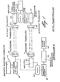
- Referring now to the drawings, Fig. 1 illustrates a first embodiment of an out of proximity alarm system having ultrasonic energy radiating and receiving means. Although ultrasonic energy radiating means are shown, other energy radiating techniques could be employed, such as radio frequency techniques. The system comprises an
interrogator module 10 andtransponder module 100. The interrogator module comprises asawtooth waveform generator 12 which frequency modulates an ultrasonic frequency carrier in F.M.modulator 14. A carrier frequency in the ultrasonic range is used, preferably a frequency in the 30 to 50 KHz range. A center frequency of 40 KHz is shown in the embodiment of Fig. 1. The frequency modulated signal is then coupled to anultrasonic transducer 16 such as a lead zirconate titanate piezo ceramic element. The ultrasonic signal having a center frequency of 40 KHz is then transmitted into the environment and is received by receivingtransducer 102, which is a part of the )transponder 100 and which converts the 40 KHz ultrasonic signal into an electrical signal. The received signal is amplified inamplifier 104. The output ofamplifier 104 is fed intomixer 106, wherein the received signal is mixed with a 10 KHz signal from fixedfrequency oscillator 109. The mixer 106 ) pr'oduces sum and difference signals having center frequencies at 30 and 50 KHz.High pass filter 109 allows only the 50 KHz signal to pass through totransducer driver 110, which is coupled toultrasonic transducer 112. Thus, a signal having a 50 KHz center frequency is retransmitted back to theinterrogator module 10. A conversion of the received signal frequency bytransponder 100 is required in order that the interrogator can distinguish between the signal transmitted by the interrogator and the signal transmitted by the transponder. -
Transducer 18 receives the signal transmitted fromtransducer 112. This signal is coupled toamplifier 20 and then mixed inmixer 22. The sum and difference output signal frequencies frommixer 22 are proportional to the phase shift between the transmitted and received signals, the phase shift being proportional to the distance between the two bodies. Abandpass filter 24 having a 10 KHz bandwidth selects the difference signal, which is then coupled to afrequency discriminator 26, which demodulates the F.M. signal, resulting in a time varying signal whose amplitude is inversely proportional to distance.Beeper alarm 28 is activated when the amplitude of the demodulated signal falls below a preset limit. Should the distance betweeninterrogator 10 andtransponder 100 increase beyond prescribed limits, the decreased amplitude of the demodulated signal will activatealarm 28. - Fig. 2 illustrates an alternative embodiment of an lout of proximity alarm system according to the invention.
- In the apparatus of Fig. 2, unit A incorporates an
ultrasonic oscillator 200 operating at a frequency in therange 30 KHz to 50 KHz whose output is gated bygate 202 to produce a burst output to the transmitterultrasonic transducer 204 for a period of 1 ms in every 100 ms. This ultrasonic signal is received and retransmitted by unit B to be received and amplified by an ultrasonic receivingtransducer 206 and band-pass amplifier 208 in unit A. - The output from
amplifier 208 is squared in apulse shaper 210 and applied to atimer 212. Thetimer 212 is gated open by thetiming pulse generator 214 and gated off by the received signal frompulse shaper 210. During this time interval, the signal from the ultrasonic oscillator coupled vialine 216 charges a timing capacitor. If thetimer 212 is not stopped before the capacitor has reached a predetermined voltage, voltagedependent switch 218 triggers, thus operating the alarm orindicator 220. - Unit B is essentially an
ultrasonic receiving transducer 250 and transmittingtransducer 252 operating at the selected frequency and may additionally comprise anamplifier stage 254. It may be possible for unit B to be a specially designed ceramic resonator which, being a passive device, would not require a battery supply. - The speed of sound waves in air at 15°C is approximately 332 m/s. The nominal distance between the units A and B is 0.60 m. Hence the transmitter to receiver path length via unit B is 1.2 m. The time taken for an ultrasonic signal to travel the path length is 3.6 msec. The timing resolution is expected to be better than + 10%, i.e., + 0.36 msec. Hence there is an expected position resolution for B of better than + 0.06 m.
- Fig. 3 illustrates a further embodiment of the alarm device. The device comprises
transmitter 300 mounted to one body, such as a briefcase, andreceiver 400 carried by the other body, such as a person. The transmitter is constructed, for example, from CMOS integrated circuit NOR logic gates to consume low power. Furthermore, the transmitter is of the burst amplifier type, so that only small bursts of energy are transmitted and consequently average current draw is low. Thetransmitter 300 comprises a first square wave oscillator ormultivibrator 310 constructed in conventional fashion which gates a second higher frequency oscillator or multivibrator 320. Oscillator 320 oscillates in the 30 to 50 KHz ultrasonic range and preferably at 40 KHz. The output of oscillator 320 is coupled in push-pull fashion totransducer 330. Thus, small bursts of ultrasonic energy are transmitted into the environment to be received byreceiver 400. -
Receiver 400 comprises receivingtransducer 410 followed bypassband amplifier 420 shown in Fig. 4 as a type SN76660 high gain IF amplifier having a 40 KHz center frequency. The output ofIF amplifier 420 is coupled to atone decoder 430 which functions as a detector stage sensitive to the transmitted 40 KHz tone. The output of the tone decoder is then coupled tolow pass filter 440 which acts as a time delay stage. When a tone signal is present, the output oftone decoder 430 goes to ground, biasing thetransistor 450 off and holding thealarm 460 deactivated. The time constant of the low pass filter insures that the base oftransistor 450 stays near ground so long as tone bursts are received i.e. the capacitor stays discharged. When the distance between the transmitter and the receiver increases beyond a predetermined amount, and the received burst signal strength falls off, the output of the tone decoder goes high, the capacitor charges up,transistor 450 is biased on after a small time delay and the alarm is activated. The alarm shown here comprises alow frequency oscillator 460 coupled to atransducer 462 such as a loudspeaker or piezoelectric crystal. - The
tone decoder 430 allows the receiver to discriminate between varying transmitter frequencies, thus providing about 200 or so different channels. A steep bandpass characteristic for the receiver is thus required. An alternative solution might utilize a numerical decode technicque, thus allowing all the transmitters and receivers to be the same with the exception of the code links set prior to sale. For example, the transmitter could send a coded signal at a low duty cycle, e.g. 5msec. long every 1 sec. This would allow, for example, 4096 (212) different code combinations. The precise number of code combinations necessary to avoid significant probability of overlap would depend on the estimates of the number of units sold. Additionally, to reduce spurious alarm triggers, a delay should be incorporated such that the receiver would need to fail to identify its code for the delay time (say 15 sees) before the alarm is triggered. - Additional delays activated by a push button could also be provided which would allow the alarm to be suppressed if the two bodies should be intentionally temporarily separated. For example, the delay mentioned above could increment in two minute steps instead of the much shorter times i.e., approximately 15 sees., contemplated in normal use.
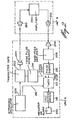
- FIG. 4 illustrates the block diagram of the preferred embodiment, a modified form of the out of proximity alarm system of Fig. 3. The system comprises
radio transmitter 500 preferably attached to the article to be protected andradio receiver 600 carried by the user. As shown in FIG. 4,transmitter 500 comprises apulse generator 510 which produces 20 msec. pulses at a 100 msec. repetition rate. In the embodiment shown in Fig. 4, -pulse generator 510 gates a radiofrequency crystal oscillator 520 on and off.Oscillator 520 may operate in any convenient R.F. band as allowed by the Federal Communications Commission in the United States or other governing authority elsewhere. The pulse burst output of R.F.oscillator 520 is then fed to an antenna and transmitted into the environment for reception byreceiver 600. In order to allow many of the alarm systems to be used in close proximity to each other, an alternative form of the invention includesdigital encoder 530. The digital encoder, may, for instance, comprise a 16 bit shift register or counter preset with a code prior to sale and having a serial output which pulse modulates R.F.oscillator 520, thus allowing up to 65,536 different code combinations.Transmitter 500 is powered by two miniature watch batteries having an approximately 3V output for maximum compactness, as shown byblock 540. - In one embodiment,
receiver 600 carried by the user comprises a radio receiver having a single conversion superheterodynefront end 625 comprisinglocal oscillator 620 andmixer 610. The pulse modulated signal fromtransmitter 500 is received by the receiver antenna and coupled in conventional fashion tomixer 610 where it beats with the local oscillator frequency fromlocal oscillator 620. The intermediate frequency signal produced is fed to I.F.amplifier 630. The output of I.F.amplifier 630 is coupled toenvelope detector 640, The detected signal is then fed into alow frequency amplifier 650 incorporating a range or sensitivity control to set the maximum reception distance. The output ofamplifier 650 is coupled to atime delay circuit 660, the purpose for which will be described hereinafter. The output oftime delay 660 is then coupled to a 1Hz multivibrator 670 which gates anaudio frequency oscillator 680 on and off to produce a pulsating audio frequency signal viatransducer 690. The purpose oftime delay 660 is to prevent activation of the alarm for a small period of time if the signal strength fromtransmitter 500 should temporarily fade, i.e., when the user moves within a room, although within range of the protected article. Again,receiver 600 may incorporate adigital decoder 700 which generates an output pulse each time a proper transmitted code is received. These pulses maintain the time delay in an off state, thus preventing activation of the alarm.Receiver 600 is powered by, for example, twosmall batteries 710, having an output voltage of 3 volts. Two size AA batteries may be used. By using circuit technology having low power consumption such as CMOS where possible, battery life should exceed one month of continuous use. - A circuit diagram for the alarm device illustrated in FIG. 4 is shown in FIGS. 5 and 6. The portions of the circuit corresponding to the blocks of FIG. 4 are indicated by phantom lines.
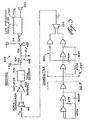
-
Pulse generator 510 comprises, in FIG. 5, anastable multivibrator 515 producing 80 msec. pulses at a 100 m sec. repetition rate. The multivibrator may be constructed in conventional form using a single quad NOR CMOS integrated circuit such as a type CD4001B for low current draw. Two of the NORgates gates oscillator 520, thus allowing sufficient current sourcing tooscillator 520. The output ofgates turn crystal oscillator 520 on and off, thus producing a burst of R.F. energy which is coupled toantenna 530 bytransformer 525 andinductor 526. The output signal toantenna 530 is the inverted form of the signal frommultivibrator 515 due to invertinggates Oscillator 520 is of conventional design, having acrystal 522 oscillating at 49.890 MHz coupled to the base oftransistor 524 and a tuned collectorcircuit comprising transformer 525 andcapacitor 527. - The receiver is illustrated in FIG. 6. The receiver comprises super-heterodyne
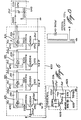
front end 625 including tunedcircuit 626 tuned to the transmitter frequency of 49.890 MHz and a frequency converter comprising fixed frequency crystal local oscillator/mixer 620 operating at a frequency of 49.435 MHz.Tuned circuit 626 includes a readily available antenna coil suitable for frequencies around 49 MHz. The mixer output difference frequency of 455 KHz is the I.F. frequency. The output of the mixer/local oscillator is coupled to 4 stage I.F.amplifier 630 constructed in conventional fashion. I.F.transformers 631 may, for example, be readily available A.M. broadcast band components. The amplified signal is then fed intocircuit 640 which functions as a simple envelope detector and voltage doubler. The detector output is then A.C. coupled to low frequency high gaininverting limiting amplifier 650. The amplifier is realized in a convenient form by using one linearlybiased gate 652 of a CMOS buffered Quad NOR gate, the remaining three gates of which are also used in the following stages of the circuit.Amplifier 650 incorporates a sensitivity control 651 for varying the gain of the amplifier and consequently the receiver range. The gain ofamplifier 650 is adjustable between approximately 10 and 5000 due toresistors gate 652 is tied to ground while the other input receives the demodulated pulsed signal. When the demodulated signal is of sufficient amplitude to saturateamplifier 650, corresponding to the receiver being within range of the transmitter, the output of NORgate 652 will be a pulsating signal having a phase opposite the signal at the input. Due to the 4th I.F. transformer take-off point (point C), the input toamplifier 650 is a pulsating signal having an on period of 80 msec and a total period of 100 msec. - The output of
amplifier 650 is then coupled totime delay circuit 660 viadiode 661. When a demodulated pulsed signal is present at the input ofamplifier 650, an inverted pulsed signal will be presented at the output ofamplifier 650. Due to the low duty cycle of the pulsed signal at the output of amplifier 650 (20 msec on, 80 msec off),capacitor 662 will be kept relatively discharged throughdiode 661. The capacitor is coupled to the input of NORgate 664 of the time delay stage, whose other input is tied to ground. Whencapacitor 662 is discharged, the output of NORgate 664 will be high. The high level of the signal keeps 1 Hzgated multivibrator 670 in an off condition, which in turn disables 2KHz audio oscillator 680, thus keeping the alarm deactivated. - When the receiver falls out of range of the transmitter or the range control setting 651 is reduced, the output of
amplifier 650 is linearly biased to its quiescent output voltage of approximately 1/2 the supply voltage.Capacitor 662 then charges up slowly throughresistor 663 towards the supply voltage and is kept from discharging by the reverse bias ondiode 661. The output oftime delay stage 664 goes low once thecapacitor 662 has charged up to the threshold voltage of the gate. The low condition at the output oftime delay stage 660 then gates multivibrator 670 on, which in turn gatesaudio oscillator 680 on and off, resulting in a pulsing audio tone from piezoelectric transducer 590. The carrier of the receiver is then warned that he has moved too far away from the personal article. Additionally, the alarm device according to the invention also has obvious use as a theft alarm. - FIG. 7 illustrates an alternative form of the transmitter output section which can replace the
crystal oscillator 520 of FIG. 5 by coupling to point A of FIG. 5. FIG. 7 shows a tunable oscillator having a ferrite rod antenna coil and variable capacitor in the collector circuit which can be tuned to the 455 KHz intermediate frequency of the receiver, thus allowing elimination of the superheterodynefront end 625 of the receiver. In place offront end 625 the simple antenna coil LC circuit of FIG. 8 tuned to the 455 KHz I.F. is used and coupled directly toI.F.amplifier 630 at point B in Fig. 6. - In the foregoing specification, the invention has been described with reference to specific exemplary embodiments thereof. It will, however, be evident that various modifications and changes may be made thereunto without departing from the broader spirit and scope of the invention as set forth in the appended claims. The specification and drawings are, accordingly, to be regarded in an illustrative rather than in a restrictive sense.
Claims (21)
1. An out of proximity alarm system comprising:
a transmitter attachable to a first body, including means for generating a radiated signal; and
a receiver attachable to a second body, comprising:
means for receiving said radiated signal;
means for demodulating said radiated signal and producing a demodulated signal;
alarm means; and
means responsive to said demodulated signal for activating said alarm means when the level of said demodulated signal falls below a threshold level;
whereby when the distance between said first and second bodies increases beyond a predetermined amount, said alarm means is activated.
2. The out of proximity alarm system recited in claim 1 wherein said means for generating a radiated signal includes ultrasonic frequency oscillator means, means for pulse modulating said ultrasonic frequency oscillator means and ultrasonic transducer transmitting means coupled to said ultrasonic frequency oscillator means and said means for receiving includes ultrasonic transducer receiving means.
3. The out of proximity alarm system recited in claim 2 wherein said means responsive to said demodulated signal comprises time delay means.
4. The out of proximity alarm system recited in claim 3 wherein said means for receiving further comprises passband amplifier means coupled to said ultrasonic transducer receiving means.
5. The out of proximity alarm system recited in claim 4 wherein said means for demodulating comprises tone decoder means.
6. The out of proximity alarm system recited in claim 5 wherein said time-delay means comprises resistor- capacitor charge storage means.
7. The out of proximity, alarm system recited in claim 6 wherein said first body is a person and said second body is a personal article.
8. The out of proximity alarm system recited in claim 6 wherein said second body is a person and said first body is a personal article.
9 An out of proximity alarm system comprising:
a transmitter attachable to a first body, including means for generating a radio frequency signal; and
a receiver attachable to a second body, comprising:
means for receiving said radio frequency signal;
means for demodulating said radio frequency signal and producing a demodulated signal; and
alarm means responsive to said demodulated signal;
one of said bodies being a person and the other of said bodies being a personal article;
whereby when the distance between said first and second bodies increases beyond a predetermined amount, said alarm means is activated.
10. The out of proximity alarm system recited in claim 9 wherein said means for generating a radio frequency signal includes radio frequency oscillator means and means for pulse modulating said radio frequency oscillator means.
11. The out of proximity alarm system recited in claim 10 wherein said receiver further comprises means for amplifying said demodulated signal.
12. The out of proximity alarm system recited in claim wherein said means for amplifying includes gain adjusting means for varying the reception range of said receiver.
13.. The out of proximity alarm system recited in claim12 wherein said receiver further comprises time-delay means responsive to said demodulated signal for activating said alarm means when the level of said demodulated signal falls below a threshold level.
14. The out of proximity alarm system recited in claim 13 wherein said means for receiving comprises:
means for converting said radio frequency signal to an intermediate frequency signal; and
intermediate frequency amplifier means coupled to said means for converting.
15. The out of proximity alarm system recited in claim 13 wherein:
said means for receiving includes a radio frequency amplifier;
said radio frequency oscillator means includes oscillator means tuned to the center frequency of said radio frequency amplifier; and
said means for receiving further includes inductor capacitor tuned circuit means coupled to the input of said radio frequency amplifier and tuned to the center frequency of said radio frequency amplifier.
16. The out of proximity alarm system recited in claim 14 or 15 wherein said means for demodulating comprises envelope detection means.
17. The out of proximity alarm system recited in claim 16'wherein said alarm means comprises:
sub-audio frequency oscillator means; and
audio frequency oscillator means coupled to said sub-audio frequency oscillator means for producing a pulsating audio alarm signal.
18. The out of proximity alarm system recited in claim'17 wherein said transmitter further includes means for digitally encoding said radio frequency signal and said receiver further includes means for digitally decoding said radio frequency signal.
19. The out of proximity alarm system recited in claim 13 wherein said time delay means comprises resistor- capacitor charge storage means.
20. An out of proximity alarm system for determining when a first body has separated from a second body by a predetermined distance comprising:
transmitting means mounted on one of said bodies comprising radio frequency oscillation means and means for pulse modulating said radio frequency oscillation means;
receiving means mounted on the other of said bodies comprising radio frequency reception means tuned to the frequency of said radio frequency oscillation means, radio frequency amplifier means, demodulation means coupled to said radio frequency amplifier means, low frequency amplifier means coupled to said demodulation means, alarm means and time delay means responsive to the demodulated signal from said demodulation means for activating said alarm means when said demodulated signal falls below a threshold level;
wherein one of said bodies is a person and the other of said bodies is a personal article.
21. The system recited in claim 22 wherein said radio frequency amplifier means comprises intermediate frequency amplifier means and said radio frequency reception means further comprises frequency conversion means.
Applications Claiming Priority (2)
| Application Number | Priority Date | Filing Date | Title |
|---|---|---|---|
| GB8126601 | 1981-09-02 | ||
| GB8126601 | 1981-09-02 |
Publications (2)
| Publication Number | Publication Date |
|---|---|
| EP0073681A2 true EP0073681A2 (en) | 1983-03-09 |
| EP0073681A3 EP0073681A3 (en) | 1983-10-12 |
Family
ID=10524274
Family Applications (1)
| Application Number | Title | Priority Date | Filing Date |
|---|---|---|---|
| EP82304584A Withdrawn EP0073681A3 (en) | 1981-09-02 | 1982-09-01 | Improvements relating to position detection devices |
Country Status (4)
| Country | Link |
|---|---|
| EP (1) | EP0073681A3 (en) |
| JP (1) | JPS5875295A (en) |
| AU (1) | AU8794782A (en) |
| GB (1) | GB2112600A (en) |
Cited By (9)
| Publication number | Priority date | Publication date | Assignee | Title |
|---|---|---|---|---|
| GB2182183A (en) * | 1985-10-26 | 1987-05-07 | Robert Peter Andow | Child vicinity radio alarm system |
| FR2598813A1 (en) * | 1986-05-15 | 1987-11-20 | Quentel Herve | METHOD FOR LOCALIZATION OF THE PRESENCE OF A VECTOR SUCH AS AN OBJECT, ANIMAL, PERSON, FIXED OR MOBILE, IN PARTICULAR A VEHICLE, AND LOCATION SYSTEM FOR IMPLEMENTING THE METHOD. |
| EP0323041A2 (en) * | 1987-12-07 | 1989-07-05 | Barry M. Wolk | Infant security system |
| FR2674351A1 (en) * | 1991-03-22 | 1992-09-25 | Schmidt Patrick | Separation detector |
| WO1993025983A1 (en) * | 1992-06-16 | 1993-12-23 | Kuehnert Eduard | Method and device for the protection of people or objects |
| EP0584261A1 (en) * | 1991-05-15 | 1994-03-02 | Bistar Electronics, Inc. | Portable anti-theft device |
| ES2085829A2 (en) * | 1994-02-17 | 1996-06-01 | Hervas Jose Luna | Improvements in the construction of alarm equipment. |
| WO2001097189A1 (en) * | 2000-06-16 | 2001-12-20 | Minouei Saberi Iman | Acoustic signal device which aids the recollection of human beings |
| CN105051565A (en) * | 2012-04-24 | 2015-11-11 | 个体定位技术有限公司 | Apparatus and methods for geolocating an individual with respect to a perimeter |
Families Citing this family (22)
| Publication number | Priority date | Publication date | Assignee | Title |
|---|---|---|---|---|
| US4593273A (en) * | 1984-03-16 | 1986-06-03 | Narcisse Bernadine O | Out-of-range personnel monitor and alarm |
| SE456372B (en) * | 1984-04-06 | 1988-09-26 | Bt Ind Ab | PROCEDURE TO HAVE AN OPERATOR-FREE MACHINE DETECTING DIFFICULTIES |
| JPS60180097U (en) * | 1984-04-28 | 1985-11-29 | ヤマハ株式会社 | alarm device |
| JPS60180096U (en) * | 1984-04-28 | 1985-11-29 | ヤマハ株式会社 | alarm device |
| JPS6257894U (en) * | 1985-09-26 | 1987-04-10 | ||
| AU589234B2 (en) * | 1985-11-20 | 1989-10-05 | Leisure Coast Auto Electrics Pty. Limited | Warning device to indicate the proximity of emergency vehicles |
| JPS6296796U (en) * | 1985-12-05 | 1987-06-20 | ||
| ZA871308B (en) * | 1987-02-24 | 1988-06-02 | Ching Kuei Liu | Burglar-alarm system for briefcase |
| GB2214340A (en) * | 1988-01-08 | 1989-08-31 | Jeffrey Kear | Lost or stolen property warning device |
| GB8810403D0 (en) * | 1988-05-03 | 1988-06-08 | Shorrock Security Systems Ltd | Radio tag alarm system |
| GB8811395D0 (en) * | 1988-05-13 | 1988-06-15 | Dick P M G | Security system |
| GB2233487A (en) * | 1988-06-06 | 1991-01-09 | Shurlok Detector Company | Vehicle protection system |
| GB8824797D0 (en) * | 1988-10-22 | 1988-11-30 | Hammond R K | Intruder alarm |
| GB2217084A (en) * | 1989-03-07 | 1989-10-18 | Mark Sillett | Personal security device |
| GB2236000A (en) * | 1989-09-01 | 1991-03-20 | Ronald George Connor | Theft or loss alarm system |
| GB2248330A (en) * | 1990-09-14 | 1992-04-01 | David William Seeman | Child/article monitoring system |
| GB2248331A (en) * | 1990-09-26 | 1992-04-01 | Harry Stuart Arfield | Surveillance alarm system |
| GB2276025A (en) * | 1993-03-13 | 1994-09-14 | Adam Peter Barwell | Radio tag alarm system |
| AUPM402394A0 (en) * | 1994-02-23 | 1994-03-17 | Monaad Corporation Pty Limited | Security access arrangement |
| GB2315898A (en) * | 1996-07-31 | 1998-02-11 | Rusty Maguire | Vicinity monitoring system |
| GB2398417A (en) * | 2003-02-12 | 2004-08-18 | John Williams | Personal property alarm system |
| DE202007011808U1 (en) * | 2007-08-23 | 2008-12-24 | Rademacher, Wilhelm | Verliersicherungsanordnung |
Citations (7)
| Publication number | Priority date | Publication date | Assignee | Title |
|---|---|---|---|---|
| FR1552189A (en) * | 1967-11-22 | 1969-01-03 | ||
| FR2301054A1 (en) * | 1975-02-12 | 1976-09-10 | Attia Chaouki | Electronic anti theft device for hand luggage - has alarm operated when fixed reference post transmitter loses contact with receiver placed in case |
| DE2647453A1 (en) * | 1976-10-21 | 1978-04-27 | Wolfgang Ing Grad Weil | Distance monitoring system for object or person - produces alarm signal when object is removed too far from its proper position |
| GB1520196A (en) * | 1976-05-27 | 1978-08-02 | Holzer W | Alarm and theft prevention apparatus |
| FR2407537A1 (en) * | 1977-10-28 | 1979-05-25 | Badens Gerard | Object distance measuring and signalling system - uses transmitter on monitored object and receiver at supervision station |
| US4260982A (en) * | 1979-10-25 | 1981-04-07 | Debenedictis Angelo P | Pulse code modulation responsive alarm system |
| GB2071956A (en) * | 1980-01-08 | 1981-09-23 | Optomech Electronic Co | Electronic alarm device |
-
1982
- 1982-09-01 GB GB08224874A patent/GB2112600A/en not_active Withdrawn
- 1982-09-01 EP EP82304584A patent/EP0073681A3/en not_active Withdrawn
- 1982-09-02 JP JP15182782A patent/JPS5875295A/en active Pending
- 1982-09-02 AU AU87947/82A patent/AU8794782A/en not_active Abandoned
Patent Citations (7)
| Publication number | Priority date | Publication date | Assignee | Title |
|---|---|---|---|---|
| FR1552189A (en) * | 1967-11-22 | 1969-01-03 | ||
| FR2301054A1 (en) * | 1975-02-12 | 1976-09-10 | Attia Chaouki | Electronic anti theft device for hand luggage - has alarm operated when fixed reference post transmitter loses contact with receiver placed in case |
| GB1520196A (en) * | 1976-05-27 | 1978-08-02 | Holzer W | Alarm and theft prevention apparatus |
| DE2647453A1 (en) * | 1976-10-21 | 1978-04-27 | Wolfgang Ing Grad Weil | Distance monitoring system for object or person - produces alarm signal when object is removed too far from its proper position |
| FR2407537A1 (en) * | 1977-10-28 | 1979-05-25 | Badens Gerard | Object distance measuring and signalling system - uses transmitter on monitored object and receiver at supervision station |
| US4260982A (en) * | 1979-10-25 | 1981-04-07 | Debenedictis Angelo P | Pulse code modulation responsive alarm system |
| GB2071956A (en) * | 1980-01-08 | 1981-09-23 | Optomech Electronic Co | Electronic alarm device |
Cited By (13)
| Publication number | Priority date | Publication date | Assignee | Title |
|---|---|---|---|---|
| GB2182183A (en) * | 1985-10-26 | 1987-05-07 | Robert Peter Andow | Child vicinity radio alarm system |
| FR2598813A1 (en) * | 1986-05-15 | 1987-11-20 | Quentel Herve | METHOD FOR LOCALIZATION OF THE PRESENCE OF A VECTOR SUCH AS AN OBJECT, ANIMAL, PERSON, FIXED OR MOBILE, IN PARTICULAR A VEHICLE, AND LOCATION SYSTEM FOR IMPLEMENTING THE METHOD. |
| EP0246960A1 (en) * | 1986-05-15 | 1987-11-25 | Compagnie Financiere Saint-Nicolas | Method for proximity locating the presence of a vector such as an object, animal, person, stationary or mobile, in particular a vehicle, and location system therefor |
| EP0323041A2 (en) * | 1987-12-07 | 1989-07-05 | Barry M. Wolk | Infant security system |
| EP0323041A3 (en) * | 1987-12-07 | 1989-10-18 | Barry M. Wolk | Infant security system |
| FR2674351A1 (en) * | 1991-03-22 | 1992-09-25 | Schmidt Patrick | Separation detector |
| EP0584261A4 (en) * | 1991-05-15 | 1994-11-17 | Bistar Electronics Inc | Portable anti-theft device. |
| EP0584261A1 (en) * | 1991-05-15 | 1994-03-02 | Bistar Electronics, Inc. | Portable anti-theft device |
| WO1993025983A1 (en) * | 1992-06-16 | 1993-12-23 | Kuehnert Eduard | Method and device for the protection of people or objects |
| US5552773A (en) * | 1992-06-16 | 1996-09-03 | K+E,Uml U+Ee Hnert; Eduard | Method and apparatus for the protection of people or objects |
| ES2085829A2 (en) * | 1994-02-17 | 1996-06-01 | Hervas Jose Luna | Improvements in the construction of alarm equipment. |
| WO2001097189A1 (en) * | 2000-06-16 | 2001-12-20 | Minouei Saberi Iman | Acoustic signal device which aids the recollection of human beings |
| CN105051565A (en) * | 2012-04-24 | 2015-11-11 | 个体定位技术有限公司 | Apparatus and methods for geolocating an individual with respect to a perimeter |
Also Published As
| Publication number | Publication date |
|---|---|
| EP0073681A3 (en) | 1983-10-12 |
| GB2112600A (en) | 1983-07-20 |
| AU8794782A (en) | 1983-03-10 |
| JPS5875295A (en) | 1983-05-06 |
Similar Documents
| Publication | Publication Date | Title |
|---|---|---|
| EP0073681A2 (en) | Improvements relating to position detection devices | |
| US5552773A (en) | Method and apparatus for the protection of people or objects | |
| US5640144A (en) | RF/ultrasonic separation distance alarm | |
| US4598272A (en) | Electronic monitoring apparatus | |
| US4260982A (en) | Pulse code modulation responsive alarm system | |
| US5032836A (en) | Guiding device for visually handicapped person | |
| US4785291A (en) | Distance monitor especially for child surveillance | |
| US4110741A (en) | Device for monitoring physical activity of persons | |
| US5337041A (en) | Personal safety guard system for stray person or pet | |
| US5486814A (en) | Baby pool guard alarm | |
| US5583488A (en) | Proximity alarm system | |
| US4714915A (en) | Portable electrostatic field safety monitor | |
| US6151278A (en) | Remote device for silent awakening | |
| US4317157A (en) | Locking device for utility locks with a key signal transmitter and a key signal receiver | |
| WO1996007998A9 (en) | Child alarm | |
| WO1996007998A1 (en) | Child alarm | |
| US4885572A (en) | Anti-theft alarm device for vehicle | |
| US4663624A (en) | Pager having receiving frame tuned by transducer | |
| GB2182183A (en) | Child vicinity radio alarm system | |
| US20040032333A1 (en) | Personal security wrist band | |
| GB2343776A (en) | Child safety distance alarm system | |
| US20040178906A1 (en) | Distance monitoring system using dual timers | |
| US4713660A (en) | Electronic proximity key and lock | |
| JPH09500226A (en) | Electronic device for establishing a continuous or discontinuous connection between a person and an object | |
| FR2351461A1 (en) | Theft deterrent system with radio transmitters - has each object fitted with transmitter providing alarm signal when carried out of range |
Legal Events
| Date | Code | Title | Description |
|---|---|---|---|
| PUAI | Public reference made under article 153(3) epc to a published international application that has entered the european phase |
Free format text: ORIGINAL CODE: 0009012 |
|
| AK | Designated contracting states |
Designated state(s): AT BE CH DE FR IT LI LU NL SE |
|
| PUAL | Search report despatched |
Free format text: ORIGINAL CODE: 0009013 |
|
| AK | Designated contracting states |
Designated state(s): AT BE CH DE FR IT LI LU NL SE |
|
| 17P | Request for examination filed |
Effective date: 19840406 |
|
| STAA | Information on the status of an ep patent application or granted ep patent |
Free format text: STATUS: THE APPLICATION IS DEEMED TO BE WITHDRAWN |
|
| 18D | Application deemed to be withdrawn |
Effective date: 19850402 |
|
| RIN1 | Information on inventor provided before grant (corrected) |
Inventor name: SINGH, KUNWAR CHANDER JEET Inventor name: GOLDNER, SANDOR |