EP0073068A2 - Theft prevention system in an automotive keyless entry system with automatic door locking - Google Patents
Theft prevention system in an automotive keyless entry system with automatic door locking Download PDFInfo
- Publication number
- EP0073068A2 EP0073068A2 EP82107871A EP82107871A EP0073068A2 EP 0073068 A2 EP0073068 A2 EP 0073068A2 EP 82107871 A EP82107871 A EP 82107871A EP 82107871 A EP82107871 A EP 82107871A EP 0073068 A2 EP0073068 A2 EP 0073068A2
- Authority
- EP
- European Patent Office
- Prior art keywords
- door
- signal
- lock
- producing
- actuator
- Prior art date
- Legal status (The legal status is an assumption and is not a legal conclusion. Google has not performed a legal analysis and makes no representation as to the accuracy of the status listed.)
- Granted
Links
- 230000002265 prevention Effects 0.000 title claims description 5
- 230000007246 mechanism Effects 0.000 claims abstract description 16
- 230000003449 preventive effect Effects 0.000 claims abstract description 15
- 230000006870 function Effects 0.000 claims abstract description 8
- 230000004044 response Effects 0.000 claims abstract description 6
- 230000000994 depressogenic effect Effects 0.000 description 5
- 230000008859 change Effects 0.000 description 1
- 238000010586 diagram Methods 0.000 description 1
- 230000004048 modification Effects 0.000 description 1
- 238000012986 modification Methods 0.000 description 1
Images
Classifications
-
- G—PHYSICS
- G07—CHECKING-DEVICES
- G07C—TIME OR ATTENDANCE REGISTERS; REGISTERING OR INDICATING THE WORKING OF MACHINES; GENERATING RANDOM NUMBERS; VOTING OR LOTTERY APPARATUS; ARRANGEMENTS, SYSTEMS OR APPARATUS FOR CHECKING NOT PROVIDED FOR ELSEWHERE
- G07C9/00—Individual registration on entry or exit
- G07C9/00174—Electronically operated locks; Circuits therefor; Nonmechanical keys therefor, e.g. passive or active electrical keys or other data carriers without mechanical keys
- G07C9/00658—Electronically operated locks; Circuits therefor; Nonmechanical keys therefor, e.g. passive or active electrical keys or other data carriers without mechanical keys operated by passive electrical keys
- G07C9/00674—Electronically operated locks; Circuits therefor; Nonmechanical keys therefor, e.g. passive or active electrical keys or other data carriers without mechanical keys operated by passive electrical keys with switch-buttons
- G07C9/0069—Electronically operated locks; Circuits therefor; Nonmechanical keys therefor, e.g. passive or active electrical keys or other data carriers without mechanical keys operated by passive electrical keys with switch-buttons actuated in a predetermined sequence
Definitions
- the present invention relates generally to a theft prevention system in an automotive keyless entry system for locking and unlocking a vehicle door with an input code inputted from externally mounted push buttons. More particularly, the invention relates to a theft prevention system adapted to produce an alarm signal when the vehicle door is opened while the keyless entry system is maintained in a door-lock mode.
- Such theft preventive alarms associate or cooperate with a cam mechanism in a cylinder lock used for locking and unlocking the vehicle door.
- An alarm switch in such a system is provided adjacent to the cam mechanism so that the alarm switch is closed while the door is locked. If the vehicle door is opened without resetting the alarm switch, an alarm signal is produced to prevent the vehicle from being stolen..
- the alarm switch is cooperable with the cam mechanism, if the cam mechanism in the door lock system can be placed in the unlocked position by a thief, the alarm switch can be turned off. This way, the conventional theft preventive alarm system cannot prevent door opening by way of operating the cam mechanism.
- a theft preventive system in an automotive keyless entry system with automatic door locking which is adapted to produce an alarm signal in response to door opening when the theft preventive system is in the door-lock position, and which is cooperative with a: door-lock system but independently operable in order to switch its operating mode from door-lock mode to door-unlock mode.
- a: theft preventive system in an automotive- keyless entry system including a push-button-type function key for operating a door-lock mechanism for locking a vehicle door.
- a memory circuit is responsive to a door-lock signal fed from the door-lock function key to set the door-lock condition. The content of the memory cannot be cleared unless a door-unlock function key is operated.
- An alarm circuit is responsive to a door-open signal fed from a door switch in the presence of a memory output indicative of the door-locking condition to produce an alarm signal.
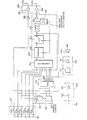
- the dr.awing shows a circuit diagram of the preferred embodiment of the theft preventive system as incorporated in an automotive keyless entry system according to the present invention.
- a door-locking actuator 52 and a door-unlocking actuator 54 are provided in the door-lock mechanism.
- the door-locking and door-unlocking actuators 52 and 54 are respectively activated by input signals inputted from a keyboard 10 with a plurality of push buttons 10a to 10f
- the push button 10f acts as a door-lock function key.
- the push button 10f is connected to the door-locking actuator 52 via an inverter 82.
- the push button 10f is also connected to a memory circuit 30 including RAM 32 in order to feed thereto an input signal indicative.of door-locking state.
- buttons 10a to 10e are connected via an address signal generator 20.
- the address signal generator 20 comprises an OR gate 22 and an address counter 24.
- the address counter 24 is adapted to tally the number of gate signals from the OR gate 22 and produce an address signal having a value representative of the counter value therein.
- the address signal from the address counter is fed to the RAM 32 in the memory circuit 30 in order to access the corresponding memory address of the RAM.
- each memory address of the RAM 32 is stored a preset value which constitutes a preset code number for door unlocking in combination with the preset values in the remaining memory addresses.
- the RAM 32 is responsive to the address signal to-access the corresponding address to produce a preset code signal to be fed to a comparator 41.. Therefore, everytime one of the push buttons 10a to 10e is depressed, the preset value in the corresponding memory address in the RAM 32 is read out and fed to the comparator 41. At the same-time-, an input signal from the depressed push button 10a to 10e, which has a value representing a code assigned to each of the push buttons, is fed to the comparator 41.
- the preset code consists of a several encoded digits, each of which has the preset value stored in the corresponding memory address of the RAM 32.
- the comparator compares the preset code from the RAM with the input code from the push button everytime one of the push buttons 10a to 10e is depressed.
- the comparator 41 produces a comparator signal when the signal values fed from the RAM and from the push buttons 10a to 10e match; in other words, the input code is the preset code as stored in R A M 32.
- the comparator signal is fed to a counter 42.
- the counter 42 is adapted to produce a counter signal when the counter value reaches a given value. Assuming the preset code consists of five encoded digits, the counted value.
- the counter signal is fed to the set input terminal of a flip-flop 43 to set the latter.
- the flip-flop 43 produces a flip-flop signal while it is set to activate a timer 44 for a-given period of time.
- the timer 44 produces a HIGH level timer signal while it is activated. and otherwise produces a LOW level timer signal.
- the HIGH level timer signal is inverted by an inverter 45 and applied to the door unlocking actuator 54 as a LOW level signal.
- the door unlocking actuator-54 is responsive-to this LOW level signal to operate the door lock mechanism to move the latter to the unlocked position.
- a one-shot monostable multivibrator 46 connected to the timer 44 is responsive to the change of the timer signal from HIGH level to LOW level to produce a trigger pulse.
- the trigger pulse of the one-shot monostable multivibrator 46 is fed to a reset input terminal of the flip-flop 43 to reset the latter.
- the trigger pulse is fed to a reset input terminal of the counter 42 to clear the counter value.
- the RAM 32 is connected to the push button 10f and is adapted to produce a door-lock signal when push button 10f is depressed.
- the RAM 32 is also connected to.the output terminal Q of the flip-flop 43 in order to receive the flip-flop signal.
- the flip-flop signal serves as a reset signal to cause the R A M 32 to cease outputting the door-lock signal when the proper input code is used to unlock the door.
- the door-lock signal is fed to an AND gate 72 in a theft preventive alarm circuit 70.
- the other input terminal of the AND gate 72 is connected to a door switch 62 in a door-open detector 60 via an inverter 6'4.
- the door switch 62 is adapted to produce a LOW level door-open signal in response to door opening.
- the LOW level door-open signal is inverted by the inverter 64 and inputted to the AND gate 72 as a HIGH level sigrzal.
- the AND gate 72 is responsive to the HIGH level signal from the door switch 62 through the inverter 64 to produce a HIGH level gate signal.
- the gate signal is inverted by an inverter 74 and then applied to an alarm device 84 as a LOW level signal.
- the alarm device 84 is responsive to the LOW level signal to produce an alarm to prevent theft of the vehicle.
- the door unlocking can be done by inputting the preset code.
- the R A M 32 stops sending the door-lock signal to the AND gate 72 of the alarm circuit. .Thus, even when the door-is opened, the alarm is not produced.
- the RAM produces the door-lock signal to be fed to the AND gate 72. At this condition, if the door is opened, AND condition of the AND gate 72 is established and thus the alarm is pr.oduced.
- the theft preventive alarm will be produced in order to reliably prevent authorized entry of the vehicle.
Abstract
Description
- The present invention relates generally to a theft prevention system in an automotive keyless entry system for locking and unlocking a vehicle door with an input code inputted from externally mounted push buttons. More particularly, the invention relates to a theft prevention system adapted to produce an alarm signal when the vehicle door is opened while the keyless entry system is maintained in a door-lock mode.
- Conventionally,, there are various theft preventive alarm systems for a door lock. Such theft preventive alarms associate or cooperate with a cam mechanism in a cylinder lock used for locking and unlocking the vehicle door. An alarm switch in such a system is provided adjacent to the cam mechanism so that the alarm switch is closed while the door is locked. If the vehicle door is opened without resetting the alarm switch, an alarm signal is produced to prevent the vehicle from being stolen.. However, since the alarm switch is cooperable with the cam mechanism, if the cam mechanism in the door lock system can be placed in the unlocked position by a thief, the alarm switch can be turned off. This way, the conventional theft preventive alarm system cannot prevent door opening by way of operating the cam mechanism.
- Therefore, it is an object of the present invention to provide a theft preventive system in an automotive keyless entry system with automatic door locking, which is adapted to produce an alarm signal in response to door opening when the theft preventive system is in the door-lock position, and which is cooperative with a: door-lock system but independently operable in order to switch its operating mode from door-lock mode to door-unlock mode.
- In order to accomplish the above-mentioned and other objects, there is provided a: theft preventive system in an automotive- keyless entry system, according to the present invention, including a push-button-type function key for operating a door-lock mechanism for locking a vehicle door. A memory circuit is responsive to a door-lock signal fed from the door-lock function key to set the door-lock condition. The content of the memory cannot be cleared unless a door-unlock function key is operated. An alarm circuit is responsive to a door-open signal fed from a door switch in the presence of a memory output indicative of the door-locking condition to produce an alarm signal.
- The invention will be more fully understood from the detailed description give herebelow and from the accompanying drawing of the preferred embodiment of the invention, which, however, should not be taken as limitative to the invention but for elucidation and explanation only.
- The dr.awing shows a circuit diagram of the preferred embodiment of the theft preventive system as incorporated in an automotive keyless entry system according to the present invention.
- Referring to the drawing, there is illustrated the preferred embodiment of the theft preventive system according to the present invention, which is incorporated in an automotive keyless .entry system with an automatic door-lock system. In order to operate a door-lock mechanism 50, a door-
locking actuator 52 and a door-unlockingactuator 54 are provided in the door-lock mechanism. The door-locking and door-unlockingactuators keyboard 10 with a plurality of push buttons 10a to 10f In the shown embodiment, the push button 10f acts as a door-lock function key. The push button 10f is connected to the door-locking actuator 52 via aninverter 82. The push button 10f is also connected to amemory circuit 30 includingRAM 32 in order to feed thereto an input signal indicative.of door-locking state. - To the
memory circuit 30, other push buttons 10a to 10e are connected via anaddress signal generator 20. - The
address signal generator 20 comprises anOR gate 22 and anaddress counter 24. Theaddress counter 24 is adapted to tally the number of gate signals from theOR gate 22 and produce an address signal having a value representative of the counter value therein. The address signal from the address counter is fed to theRAM 32 in thememory circuit 30 in order to access the corresponding memory address of the RAM. - In each memory address of the
RAM 32 is stored a preset value which constitutes a preset code number for door unlocking in combination with the preset values in the remaining memory addresses. TheRAM 32 is responsive to the address signal to-access the corresponding address to produce a preset code signal to be fed to acomparator 41.. Therefore, everytime one of the push buttons 10a to 10e is depressed, the preset value in the corresponding memory address in theRAM 32 is read out and fed to thecomparator 41. At the same-time-, an input signal from the depressed push button 10a to 10e, which has a value representing a code assigned to each of the push buttons, is fed to thecomparator 41. - The preset code consists of a several encoded digits, each of which has the preset value stored in the corresponding memory address of the
RAM 32. The comparator compares the preset code from the RAM with the input code from the push button everytime one of the push buttons 10a to 10e is depressed. Thecomparator 41 produces a comparator signal when the signal values fed from the RAM and from the push buttons 10a to 10e match; in other words, the input code is the preset code as stored in RAM 32. The comparator signal is fed to acounter 42. Thecounter 42 is adapted to produce a counter signal when the counter value reaches a given value. Assuming the preset code consists of five encoded digits, the counted value. in thecounter 42 necessary to produce the counter signal is five. The counter signal is fed to the set input terminal of a flip-flop 43 to set the latter. The flip-flop 43 produces a flip-flop signal while it is set to activate atimer 44 for a-given period of time. Thetimer 44. produces a HIGH level timer signal while it is activated. and otherwise produces a LOW level timer signal. The HIGH level timer signal is inverted by aninverter 45 and applied to thedoor unlocking actuator 54 as a LOW level signal. The door unlocking actuator-54 is responsive-to this LOW level signal to operate the door lock mechanism to move the latter to the unlocked position. - After the given period expires, the time signal level turns from HIGH to LOW. A one-shot
monostable multivibrator 46 connected to thetimer 44 is responsive to the change of the timer signal from HIGH level to LOW level to produce a trigger pulse. The trigger pulse of the one-shotmonostable multivibrator 46 is fed to a reset input terminal of the flip-flop 43 to reset the latter. At the same time, the trigger pulse is fed to a reset input terminal of thecounter 42 to clear the counter value. - On the other hand, the
RAM 32 is connected to the push button 10f and is adapted to produce a door-lock signal when push button 10f is depressed. TheRAM 32 is also connected to.the output terminal Q of the flip-flop 43 in order to receive the flip-flop signal. The flip-flop signal serves as a reset signal to cause the RAM 32 to cease outputting the door-lock signal when the proper input code is used to unlock the door. The door-lock signal is fed to anAND gate 72 in a theft preventive alarm circuit 70. The other input terminal of theAND gate 72 is connected to adoor switch 62 in a door-open detector 60 via an inverter 6'4. Thedoor switch 62 is adapted to produce a LOW level door-open signal in response to door opening. The LOW level door-open signal is inverted by theinverter 64 and inputted to theAND gate 72 as a HIGH level sigrzal. In the presence of the door-lock signal from theRAM 32, theAND gate 72 is responsive to the HIGH level signal from thedoor switch 62 through theinverter 64 to produce a HIGH level gate signal. The gate signal is inverted by aninverter 74 and then applied to analarm device 84 as a LOW level signal. Thealarm device 84 is responsive to the LOW level signal to produce an alarm to prevent theft of the vehicle. - As will be appreciated hereabove, in the shown embodiment, the door unlocking can be done by inputting the preset code. At this case, the RAM 32 stops sending the door-lock signal to the
AND gate 72 of the alarm circuit. .Thus, even when the door-is opened, the alarm is not produced. Alternatively, when the push button lOf is depressed and thus the door-lock mechanism is placed in the door-locked position, the RAM produces the door-lock signal to be fed to the ANDgate 72. At this condition, if the door is opened, AND condition of the ANDgate 72 is established and thus the alarm is pr.oduced. - Therefore, even if the- door-lock mechanism is damaged or manipulated into the door-unlocked position by a thief, since the
RAM 32 continues to output the door-lock signal unless it is turned off by the preset input code, the theft preventive alarm will be produced in order to reliably prevent authorized entry of the vehicle. - While the present invention has been described in detail in terms of the preferred embodiment, the invention can be modified or embodied otherwise in any way without departing from the principle of the invention. Therefore, it should be appreciated' that the prevent invention includes all of possible modifications and embodiments pertaining to the gist of the invention.
Claims (7)
Applications Claiming Priority (2)
| Application Number | Priority Date | Filing Date | Title |
|---|---|---|---|
| JP56132565A JPS5835694A (en) | 1981-08-26 | 1981-08-26 | Anti-theft controller for automobile |
| JP132565/81 | 1981-08-26 |
Publications (3)
| Publication Number | Publication Date |
|---|---|
| EP0073068A2 true EP0073068A2 (en) | 1983-03-02 |
| EP0073068A3 EP0073068A3 (en) | 1984-03-28 |
| EP0073068B1 EP0073068B1 (en) | 1987-07-15 |
Family
ID=15084269
Family Applications (1)
| Application Number | Title | Priority Date | Filing Date |
|---|---|---|---|
| EP82107871A Expired EP0073068B1 (en) | 1981-08-26 | 1982-08-26 | Theft prevention system in an automotive keyless entry system with automatic door locking |
Country Status (4)
| Country | Link |
|---|---|
| US (1) | US4638292A (en) |
| EP (1) | EP0073068B1 (en) |
| JP (1) | JPS5835694A (en) |
| DE (1) | DE3276763D1 (en) |
Cited By (6)
| Publication number | Priority date | Publication date | Assignee | Title |
|---|---|---|---|---|
| EP0158354A2 (en) * | 1984-04-12 | 1985-10-16 | Nissan Motor Co., Ltd. | Keyless entry system for automotive devices with compact, portable wireles code transmitter, and feature for preventing users from locking transmitter in vehicle |
| US4688036A (en) * | 1983-11-29 | 1987-08-18 | Nissan Motor Company, Limited | Keyless entry system for automotive vehicle with power consumption saving feature |
| US4761645A (en) * | 1984-03-01 | 1988-08-02 | Nissan Motor Company, Limited | Keyless entry system for automotive devices including steering lock device with compact, portable wireless code transmitter |
| GB2215387A (en) * | 1988-02-03 | 1989-09-20 | John Paul Keeble | Central locking system for buildings |
| CN103150801A (en) * | 2013-03-23 | 2013-06-12 | 北京兴科迪科技有限公司 | Electronic intelligent key and vehicle door automatic controller used in vehicle |
| CN104484915A (en) * | 2014-11-10 | 2015-04-01 | 广东力维智能锁业有限公司 | Intelligent door lock grading defence organizing method and grading defence organizing system thereof |
Families Citing this family (22)
| Publication number | Priority date | Publication date | Assignee | Title |
|---|---|---|---|---|
| FR2554665B1 (en) * | 1983-11-04 | 1986-07-25 | Radiotechnique | MICROPROCESSOR ANTI-THEFT DEVICE FOR RADIO APPARATUS |
| JPH0617648Y2 (en) * | 1984-10-18 | 1994-05-11 | 株式会社ユ−シン | Anti-theft device for automobile |
| JPH0617649Y2 (en) * | 1984-11-27 | 1994-05-11 | 株式会社ユ−シン | Anti-theft device for automobile |
| US4845492A (en) * | 1984-12-10 | 1989-07-04 | Richard G. Cobb | Article monitoring system with printing capability |
| JPS61107666U (en) * | 1984-12-20 | 1986-07-08 | ||
| JPS61177953U (en) * | 1985-04-26 | 1986-11-06 | ||
| US4749873A (en) * | 1985-07-25 | 1988-06-07 | Toyota Jidosha Kabushiki Kaisha | Anti-theft device for an automobile |
| US4980666A (en) * | 1985-07-26 | 1990-12-25 | Hwang Shih Ming | Two-step alarm disarming device with automatic rearming feature |
| JPH0635836Y2 (en) * | 1986-01-22 | 1994-09-21 | トヨタ自動車株式会社 | Anti-theft device for patrol car |
| US5181010A (en) * | 1988-08-04 | 1993-01-19 | Chick James S | Automotive security system with discrimination between tampering and attack |
| US5406270A (en) * | 1992-06-29 | 1995-04-11 | Prince Corporation | Dead switch vehicle operator identification |
| DE4323813C2 (en) * | 1992-07-17 | 1999-02-18 | Mitsui Mining & Smelting Co | Vehicle door locking device with overlock mechanism |
| FR2694778B1 (en) * | 1992-08-11 | 1995-04-14 | Smh Management Services Ag | Safety device intended for opening and / or closing the door, in particular for a motor vehicle. |
| US5780987A (en) * | 1995-05-17 | 1998-07-14 | The Chamberlain Group, Inc. | Barrier operator having system for detecting attempted forced entry |
| US7106171B1 (en) | 1998-04-16 | 2006-09-12 | Burgess James P | Keyless command system for vehicles and other applications |
| US20050242923A1 (en) * | 1998-04-16 | 2005-11-03 | David Pearson | Passive entry systems for vehicles and other applications |
| US6031465A (en) * | 1998-04-16 | 2000-02-29 | Burgess; James P. | Keyless entry system for vehicles in particular |
| US7336174B1 (en) | 2001-08-09 | 2008-02-26 | Key Control Holding, Inc. | Object tracking system with automated system control and user identification |
| US6906612B2 (en) * | 2002-04-11 | 2005-06-14 | Lear Corporation | System and method for vehicle passive entry having inside/outside detection |
| US6819229B2 (en) | 2002-06-03 | 2004-11-16 | Lear Corporation | Countermeasure system and method for vehicle passive entry system |
| US20040229560A1 (en) * | 2002-10-10 | 2004-11-18 | Maloney William C. | Methods of tracking and verifying human assets |
| CN106740673B (en) * | 2016-12-23 | 2019-06-11 | 北汽福田汽车股份有限公司 | The control method and device of car lock system |
Citations (4)
| Publication number | Priority date | Publication date | Assignee | Title |
|---|---|---|---|---|
| US3829834A (en) * | 1973-09-10 | 1974-08-13 | J Frankland | Electrical combination lock apparatus |
| US3878511A (en) * | 1973-12-03 | 1975-04-15 | Mosler Safe Co | Vault protected wtih electronic time and combination lock |
| US4114147A (en) * | 1977-03-24 | 1978-09-12 | Hile John R | Code combination property alarm system |
| EP0002948A1 (en) * | 1977-12-27 | 1979-07-11 | Ford Motor Company Limited | Keyless locking and entry system |
Family Cites Families (20)
| Publication number | Priority date | Publication date | Assignee | Title |
|---|---|---|---|---|
| US3593816A (en) * | 1968-12-30 | 1971-07-20 | Aisin Seiki | Automotive door lock |
| US3587051A (en) * | 1969-12-11 | 1971-06-22 | North American Res Corp | Electronic combination switching device |
| US3633167A (en) * | 1970-05-25 | 1972-01-04 | Phinizy R B | Security system |
| US3691396A (en) * | 1971-08-09 | 1972-09-12 | Gen Motors Corp | Electronic combination door and ignition lock |
| US3710316A (en) * | 1971-09-01 | 1973-01-09 | G Kromer | Vehicle electrical combination lock |
| US3754213A (en) * | 1971-09-03 | 1973-08-21 | T Morroni | Electronic combination lock system |
| US3781854A (en) * | 1972-02-14 | 1973-12-25 | Educated Vehicle Systems Inc | Auto alarm arming system |
| US3764859A (en) * | 1972-05-30 | 1973-10-09 | Gross W | Electronic lock apparatus |
| US3812403A (en) * | 1972-06-29 | 1974-05-21 | K Gartner | Electronic combination lock including sequential signal generator and signal display |
| US3751718A (en) * | 1972-11-16 | 1973-08-07 | L Hanchett | Programmable electric locking system |
| US3831065A (en) * | 1973-04-06 | 1974-08-20 | Integrated Conversion Tech | Electronic push button combination lock |
| US3871474A (en) * | 1973-06-06 | 1975-03-18 | Chrysler Corp | Electric automatic door locking system |
| US3893073A (en) * | 1974-02-06 | 1975-07-01 | Westinghouse Electric Corp | Keyless control mechanism |
| US4205300A (en) * | 1976-08-30 | 1980-05-27 | Techne Electronics, Ltd. | Vehicle antitheft alarm |
| US4206491A (en) * | 1977-08-03 | 1980-06-03 | Kkf Corporation | Entry system |
| US4189712A (en) * | 1977-11-09 | 1980-02-19 | Lemelson Jerome H | Switch and lock activating system and method |
| JPS54126427A (en) * | 1978-03-24 | 1979-10-01 | Sharp Corp | Sound generator for electronic apparatus |
| US4222088A (en) * | 1978-09-27 | 1980-09-09 | Burton Richard H | Electronic lock |
| US4197524A (en) * | 1978-12-29 | 1980-04-08 | General Electric Company | Tap-actuated lock and method of actuating the lock |
| DE2913955C3 (en) * | 1979-04-06 | 1981-10-01 | Matthias Design Corp., Los Angeles | Suitcase with a built-in electronic lock |
-
1981
- 1981-08-26 JP JP56132565A patent/JPS5835694A/en active Granted
-
1982
- 1982-08-24 US US06/411,096 patent/US4638292A/en not_active Expired - Lifetime
- 1982-08-26 EP EP82107871A patent/EP0073068B1/en not_active Expired
- 1982-08-26 DE DE8282107871T patent/DE3276763D1/en not_active Expired
Patent Citations (4)
| Publication number | Priority date | Publication date | Assignee | Title |
|---|---|---|---|---|
| US3829834A (en) * | 1973-09-10 | 1974-08-13 | J Frankland | Electrical combination lock apparatus |
| US3878511A (en) * | 1973-12-03 | 1975-04-15 | Mosler Safe Co | Vault protected wtih electronic time and combination lock |
| US4114147A (en) * | 1977-03-24 | 1978-09-12 | Hile John R | Code combination property alarm system |
| EP0002948A1 (en) * | 1977-12-27 | 1979-07-11 | Ford Motor Company Limited | Keyless locking and entry system |
Cited By (9)
| Publication number | Priority date | Publication date | Assignee | Title |
|---|---|---|---|---|
| US4688036A (en) * | 1983-11-29 | 1987-08-18 | Nissan Motor Company, Limited | Keyless entry system for automotive vehicle with power consumption saving feature |
| US4761645A (en) * | 1984-03-01 | 1988-08-02 | Nissan Motor Company, Limited | Keyless entry system for automotive devices including steering lock device with compact, portable wireless code transmitter |
| EP0158354A2 (en) * | 1984-04-12 | 1985-10-16 | Nissan Motor Co., Ltd. | Keyless entry system for automotive devices with compact, portable wireles code transmitter, and feature for preventing users from locking transmitter in vehicle |
| EP0158354B1 (en) * | 1984-04-12 | 1988-12-28 | Nissan Motor Co., Ltd. | Keyless entry system for automotive devices with compact, portable wireles code transmitter, and feature for preventing users from locking transmitter in vehicle |
| GB2215387A (en) * | 1988-02-03 | 1989-09-20 | John Paul Keeble | Central locking system for buildings |
| GB2215387B (en) * | 1988-02-03 | 1992-08-26 | John Paul Keeble | Central locking system for buildings |
| CN103150801A (en) * | 2013-03-23 | 2013-06-12 | 北京兴科迪科技有限公司 | Electronic intelligent key and vehicle door automatic controller used in vehicle |
| CN103150801B (en) * | 2013-03-23 | 2015-01-28 | 北京兴科迪科技有限公司 | Electronic intelligent key and vehicle door automatic controller used in vehicle |
| CN104484915A (en) * | 2014-11-10 | 2015-04-01 | 广东力维智能锁业有限公司 | Intelligent door lock grading defence organizing method and grading defence organizing system thereof |
Also Published As
| Publication number | Publication date |
|---|---|
| EP0073068A3 (en) | 1984-03-28 |
| DE3276763D1 (en) | 1987-08-20 |
| EP0073068B1 (en) | 1987-07-15 |
| JPH0150613B2 (en) | 1989-10-31 |
| US4638292A (en) | 1987-01-20 |
| JPS5835694A (en) | 1983-03-02 |
Similar Documents
| Publication | Publication Date | Title |
|---|---|---|
| EP0073068A2 (en) | Theft prevention system in an automotive keyless entry system with automatic door locking | |
| US4972182A (en) | Electronic security lock | |
| EP0518873B1 (en) | Security arrangement | |
| US4486806A (en) | Electronic door locking system for an automotive vehicle | |
| US4895009A (en) | Door-locking system for a motor vehicle | |
| US7511602B2 (en) | Keyless entry module and method | |
| US4206491A (en) | Entry system | |
| US4274080A (en) | Magnetic security system | |
| US4671086A (en) | Redundant electrically controlled locking apparatus | |
| US4428024A (en) | Electronic door locking system for an automotive vehicle | |
| EP0076480B1 (en) | Mischief preventive electronic lock device | |
| US4937560A (en) | Security system with door deadbolt interlock | |
| US4463349A (en) | Electronic lock system with audible entry monitor | |
| EP0084351B1 (en) | Electronic door locking system for an automotive vehicle | |
| JPS6316550B2 (en) | ||
| US4818971A (en) | False alarm resistant burglar alarm system | |
| US4926160A (en) | Means for controlling power door locks with an automobile burglar alarm | |
| US5309152A (en) | Security system with membrane switches to detect binary code on mechanical key | |
| GB2380224A (en) | A locking arrangement comprising two independent locking mechanisms | |
| JPH0235818B2 (en) | ||
| GB2153896A (en) | Safes | |
| WO1995008458A1 (en) | Arrangement in a car alarm | |
| JP2902080B2 (en) | Operation control device | |
| JP2585929Y2 (en) | Electric lock device with door lock warning release function | |
| JPH0685878U (en) | Locking and unlocking operation device for vehicles |
Legal Events
| Date | Code | Title | Description |
|---|---|---|---|
| PUAI | Public reference made under article 153(3) epc to a published international application that has entered the european phase |
Free format text: ORIGINAL CODE: 0009012 |
|
| 17P | Request for examination filed |
Effective date: 19820826 |
|
| AK | Designated contracting states |
Designated state(s): DE FR GB |
|
| PUAL | Search report despatched |
Free format text: ORIGINAL CODE: 0009013 |
|
| AK | Designated contracting states |
Designated state(s): DE FR GB |
|
| RAP1 | Party data changed (applicant data changed or rights of an application transferred) |
Owner name: KOKUSAN KINZOKU KOGYO CO. LTD. Owner name: NISSAN MOTOR CO., LTD. |
|
| GRAA | (expected) grant |
Free format text: ORIGINAL CODE: 0009210 |
|
| AK | Designated contracting states |
Kind code of ref document: B1 Designated state(s): DE FR GB |
|
| REF | Corresponds to: |
Ref document number: 3276763 Country of ref document: DE Date of ref document: 19870820 |
|
| ET | Fr: translation filed | ||
| PLBE | No opposition filed within time limit |
Free format text: ORIGINAL CODE: 0009261 |
|
| STAA | Information on the status of an ep patent application or granted ep patent |
Free format text: STATUS: NO OPPOSITION FILED WITHIN TIME LIMIT |
|
| 26N | No opposition filed | ||
| PGFP | Annual fee paid to national office [announced via postgrant information from national office to epo] |
Ref country code: FR Payment date: 20010810 Year of fee payment: 20 |
|
| PGFP | Annual fee paid to national office [announced via postgrant information from national office to epo] |
Ref country code: DE Payment date: 20010820 Year of fee payment: 20 |
|
| PGFP | Annual fee paid to national office [announced via postgrant information from national office to epo] |
Ref country code: GB Payment date: 20010822 Year of fee payment: 20 |
|
| REG | Reference to a national code |
Ref country code: GB Ref legal event code: IF02 |
|
| PG25 | Lapsed in a contracting state [announced via postgrant information from national office to epo] |
Ref country code: GB Free format text: LAPSE BECAUSE OF EXPIRATION OF PROTECTION Effective date: 20020825 |
|
| REG | Reference to a national code |
Ref country code: GB Ref legal event code: PE20 Effective date: 20020825 |