EP0071016B1 - Apparatus for production of expanded polystyrene panels - Google Patents
Apparatus for production of expanded polystyrene panels Download PDFInfo
- Publication number
- EP0071016B1 EP0071016B1 EP82105521A EP82105521A EP0071016B1 EP 0071016 B1 EP0071016 B1 EP 0071016B1 EP 82105521 A EP82105521 A EP 82105521A EP 82105521 A EP82105521 A EP 82105521A EP 0071016 B1 EP0071016 B1 EP 0071016B1
- Authority
- EP
- European Patent Office
- Prior art keywords
- panels
- mold
- mold member
- secured
- expanded
- Prior art date
- Legal status (The legal status is an assumption and is not a legal conclusion. Google has not performed a legal analysis and makes no representation as to the accuracy of the status listed.)
- Expired
Links
Images


Classifications
-
- B—PERFORMING OPERATIONS; TRANSPORTING
- B29—WORKING OF PLASTICS; WORKING OF SUBSTANCES IN A PLASTIC STATE IN GENERAL
- B29C—SHAPING OR JOINING OF PLASTICS; SHAPING OF MATERIAL IN A PLASTIC STATE, NOT OTHERWISE PROVIDED FOR; AFTER-TREATMENT OF THE SHAPED PRODUCTS, e.g. REPAIRING
- B29C44/00—Shaping by internal pressure generated in the material, e.g. swelling or foaming ; Producing porous or cellular expanded plastics articles
- B29C44/34—Auxiliary operations
- B29C44/3415—Heating or cooling
- B29C44/3426—Heating by introducing steam in the mould
- B29C44/3434—Heating by introducing steam in the mould by using a sheet, grid, etc. to distribute the steam in the mould
-
- B—PERFORMING OPERATIONS; TRANSPORTING
- B29—WORKING OF PLASTICS; WORKING OF SUBSTANCES IN A PLASTIC STATE IN GENERAL
- B29C—SHAPING OR JOINING OF PLASTICS; SHAPING OF MATERIAL IN A PLASTIC STATE, NOT OTHERWISE PROVIDED FOR; AFTER-TREATMENT OF THE SHAPED PRODUCTS, e.g. REPAIRING
- B29C44/00—Shaping by internal pressure generated in the material, e.g. swelling or foaming ; Producing porous or cellular expanded plastics articles
- B29C44/02—Shaping by internal pressure generated in the material, e.g. swelling or foaming ; Producing porous or cellular expanded plastics articles for articles of definite length, i.e. discrete articles
- B29C44/10—Applying counter-pressure during expanding
-
- B—PERFORMING OPERATIONS; TRANSPORTING
- B29—WORKING OF PLASTICS; WORKING OF SUBSTANCES IN A PLASTIC STATE IN GENERAL
- B29C—SHAPING OR JOINING OF PLASTICS; SHAPING OF MATERIAL IN A PLASTIC STATE, NOT OTHERWISE PROVIDED FOR; AFTER-TREATMENT OF THE SHAPED PRODUCTS, e.g. REPAIRING
- B29C44/00—Shaping by internal pressure generated in the material, e.g. swelling or foaming ; Producing porous or cellular expanded plastics articles
- B29C44/34—Auxiliary operations
- B29C44/36—Feeding the material to be shaped
- B29C44/38—Feeding the material to be shaped into a closed space, i.e. to make articles of definite length
- B29C44/44—Feeding the material to be shaped into a closed space, i.e. to make articles of definite length in solid form
- B29C44/445—Feeding the material to be shaped into a closed space, i.e. to make articles of definite length in solid form in the form of expandable granules, particles or beads
-
- B—PERFORMING OPERATIONS; TRANSPORTING
- B29—WORKING OF PLASTICS; WORKING OF SUBSTANCES IN A PLASTIC STATE IN GENERAL
- B29C—SHAPING OR JOINING OF PLASTICS; SHAPING OF MATERIAL IN A PLASTIC STATE, NOT OTHERWISE PROVIDED FOR; AFTER-TREATMENT OF THE SHAPED PRODUCTS, e.g. REPAIRING
- B29C44/00—Shaping by internal pressure generated in the material, e.g. swelling or foaming ; Producing porous or cellular expanded plastics articles
- B29C44/34—Auxiliary operations
- B29C44/36—Feeding the material to be shaped
- B29C44/46—Feeding the material to be shaped into an open space or onto moving surfaces, i.e. to make articles of indefinite length
- B29C44/50—Feeding the material to be shaped into an open space or onto moving surfaces, i.e. to make articles of indefinite length using pressure difference, e.g. by extrusion or by spraying
- B29C44/505—Feeding the material to be shaped into an open space or onto moving surfaces, i.e. to make articles of indefinite length using pressure difference, e.g. by extrusion or by spraying extruding the compound through a flat die
-
- B—PERFORMING OPERATIONS; TRANSPORTING
- B29—WORKING OF PLASTICS; WORKING OF SUBSTANCES IN A PLASTIC STATE IN GENERAL
- B29C—SHAPING OR JOINING OF PLASTICS; SHAPING OF MATERIAL IN A PLASTIC STATE, NOT OTHERWISE PROVIDED FOR; AFTER-TREATMENT OF THE SHAPED PRODUCTS, e.g. REPAIRING
- B29C48/00—Extrusion moulding, i.e. expressing the moulding material through a die or nozzle which imparts the desired form; Apparatus therefor
- B29C48/03—Extrusion moulding, i.e. expressing the moulding material through a die or nozzle which imparts the desired form; Apparatus therefor characterised by the shape of the extruded material at extrusion
- B29C48/07—Flat, e.g. panels
-
- B—PERFORMING OPERATIONS; TRANSPORTING
- B29—WORKING OF PLASTICS; WORKING OF SUBSTANCES IN A PLASTIC STATE IN GENERAL
- B29C—SHAPING OR JOINING OF PLASTICS; SHAPING OF MATERIAL IN A PLASTIC STATE, NOT OTHERWISE PROVIDED FOR; AFTER-TREATMENT OF THE SHAPED PRODUCTS, e.g. REPAIRING
- B29C33/00—Moulds or cores; Details thereof or accessories therefor
- B29C33/30—Mounting, exchanging or centering
- B29C33/301—Modular mould systems [MMS], i.e. moulds built up by stacking mould elements, e.g. plates, blocks, rods
-
- B—PERFORMING OPERATIONS; TRANSPORTING
- B29—WORKING OF PLASTICS; WORKING OF SUBSTANCES IN A PLASTIC STATE IN GENERAL
- B29C—SHAPING OR JOINING OF PLASTICS; SHAPING OF MATERIAL IN A PLASTIC STATE, NOT OTHERWISE PROVIDED FOR; AFTER-TREATMENT OF THE SHAPED PRODUCTS, e.g. REPAIRING
- B29C48/00—Extrusion moulding, i.e. expressing the moulding material through a die or nozzle which imparts the desired form; Apparatus therefor
-
- B—PERFORMING OPERATIONS; TRANSPORTING
- B29—WORKING OF PLASTICS; WORKING OF SUBSTANCES IN A PLASTIC STATE IN GENERAL
- B29K—INDEXING SCHEME ASSOCIATED WITH SUBCLASSES B29B, B29C OR B29D, RELATING TO MOULDING MATERIALS OR TO MATERIALS FOR MOULDS, REINFORCEMENTS, FILLERS OR PREFORMED PARTS, e.g. INSERTS
- B29K2105/00—Condition, form or state of moulded material or of the material to be shaped
- B29K2105/25—Solid
- B29K2105/253—Preform
- B29K2105/256—Sheets, plates, blanks or films
-
- B—PERFORMING OPERATIONS; TRANSPORTING
- B29—WORKING OF PLASTICS; WORKING OF SUBSTANCES IN A PLASTIC STATE IN GENERAL
- B29L—INDEXING SCHEME ASSOCIATED WITH SUBCLASS B29C, RELATING TO PARTICULAR ARTICLES
- B29L2007/00—Flat articles, e.g. films or sheets
-
- Y—GENERAL TAGGING OF NEW TECHNOLOGICAL DEVELOPMENTS; GENERAL TAGGING OF CROSS-SECTIONAL TECHNOLOGIES SPANNING OVER SEVERAL SECTIONS OF THE IPC; TECHNICAL SUBJECTS COVERED BY FORMER USPC CROSS-REFERENCE ART COLLECTIONS [XRACs] AND DIGESTS
- Y10—TECHNICAL SUBJECTS COVERED BY FORMER USPC
- Y10S—TECHNICAL SUBJECTS COVERED BY FORMER USPC CROSS-REFERENCE ART COLLECTIONS [XRACs] AND DIGESTS
- Y10S264/00—Plastic and nonmetallic article shaping or treating: processes
- Y10S264/15—Aging of foamed resin products
Definitions
- the present invention is concerned with an apparatus for the production of expanded polystyrene panels by heating and expanding pre-extruded panels in a multiple mold using hot aeriform fluid, and more specifically, expanded polystyrene panels having a thickness of 20-80 mm which are primarily used for a thermal insulation of walls and flat roofs in various buildings.
- the quality of the panels depends upon their longevity, heat transmission factor, density, compressive and flexural strength and dimensional stability.
- Expanded polystyrene panels are currently produced by the industry using two basic processes.
- the first process involves the pre-expansion of expandable polystyrene beads and the subsequent additional expansion of such beads into suitable molds by means of steam.
- Panels of very low density, for example, 10 kg/m 3 can be obtained by this process while panels normally accepted for insulation in buildings have a density such as 50-20 kg/m 3 .
- Even though such panels are relatively inexpensive to produce they are used less frequently because they tend to crush after a period of time since the cohesion keeping the single particles of expanded material together, while poor at the time of production, has a tendency to diminish still further.
- the panels are made by extruding molten polystyrene containing a blowing agent, for instance, Freon 12 or a mixture of Freon 11 and 12, into the atmosphere where the mass expands.
- Panels manufactured according to the second process generally have a much higher density, for example 30-45 kg/m 3 , compared to panels manufactured in accordance with the first process and are considered more advantageous due to longer life and better mechanical properties, chiefly stiffness and toughness which are much higher than in the first case.
- Patent GB-A-1 109 297 discloses a process for a production of polystyrene panels comprising: preparation of a pre-expanded article by extrusion, conditioning the article at room temperature, and forming of pre-expanded article in a mold box using a hot fluid, at least 60% of the volumetric increase of the mass being affected to their average increase in thickness.
- pre-expanded panels extruded from polystyrene and other similar polymers having a density of 30-45 kg/m 3 can successfully be transformed into panels having a density of 16-24 kg/m 3 and a thickness generally twice as great as the original panels.
- an extruded panel of expanded polystyrene tends to expand further when heated to a temperature higher than its softening point, for example 100-120°C. In this way the above tendency is exploited in an efficient industrial manner controlling at the same time such tendency in the best way possible for obtaining panels having a very low density and at the same time having an exceptional thickness and toughness.
- FIGs 1-5 several mold members have been set up parallel to each other for pivotal movement to allow for the easy insertion and removal of panels.
- a plurality of mold members 200 are each pivoted at 204 to a support member 202 in parallel relationship to each other.
- the construction of the individual mold member 200, which is identical to each other, is best seen in Figures 3, 4 and 5.
- Each mold member 200 is comprised of two flat parallel plates 206 which may be of aluminium or any other suitable heat conductive material.
- a plurality of parallel spaced hollow aluminum tubes 208 having a substantially square cross-section are secured between the plates 206 as best seen in Figure 3.
- Iron bars 207 and 209 are secured between the aluminium sheets 206 along the edges thereof to form a rigid assembly.
- a pair of elongated U-shaped channels 210 and 212 are secured to the surfaces of the plates 206 along the shorter edges of the rectilinear mold assembly.
- the iron bars 209 are machined at their ends to receive the pivots 214 which allow the mold member to rotate relative to the support frame 202.
- a pair of L-shaped aluminium strips 216 and 218 are secured to the opposite side of each mold member 200 by means of bolts, screws or the like along the longer edges of each mold member.
- a shorter L-shaped aluminium strip 220 is secured to one side of the mold member along one short edge of the mold member adjacent to the U-shaped channel member 212.
- the mold member 200 may be assembled by means of nuts and bolts or any other suitable means and provides a substantially hollow interior for the passage of a fluid therethrough.
- the ends of the channel 208 are open at the opposite ends as are the spaces between each of the channels 208 to facilitate the passage of the treating fluid therethrough.
- the faces of the L-shaped strips 216, 218 and 200 which face towards the interior of a mold, form an angle with the aluminium sheets 206 slightly greater than 90° to facilitate the removal of the formed panels upon opening of the mold.
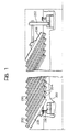
- two adjacent mold members 200 are shown in section and are disposed parallel to each other at an angle a with respect to the horizontal plane.
- the individual mold member 200 may be rotated from the position shown in Figure 1 wherein they are disposed at said angle a relative to the horizontal plane to the position shown in Figure 2 wherein the individual mold members are disposed at said angle a relative to the horizontal plane.
- An extruded, pre-expanded panel is adapted to be located between each adjacent pair of mold members 200. As viewed in Figure 3, the extruded panel would be placed between the upwardly projecting L-shaped strip 216 on one member 200 and the downwardly extending L-shaped strip 218 on the adjacent mold member which are spaced apart a distance 1 2 . This distance 1 2 is equal to the desired width of the final expanded panel, while the other two dimensions of said panel are called, respectively, I 1 , its length, and 1 3 , its height.
- the gauge of thickness of the formed panel By varying the angle a of the individual mold elements 200 with respect to the horizontal plane or, less preferably, varying the center distance between the hinge pins for the individual mold members. It has been found that the relationship between the gauge T of the panel, the distance I between the hinge centers, the thickness S of the mold elements 200 and the angle formed by the mold elements 200 with the horizontal plane is the followinq: where
- I is equal to 130 mm and S is equal to 23 mm.
- the thickness of the panel within a wide range by varying the angle a of the members 200 within a range which is efficient for good operation.
- the thickness of the formed panel can be varied by merely changing the angle a of the mold members 200 and replacing the L-shaped side plates of the mold. It should be noted that when varying the angle a the width of the panel as illustrated by the distance 1 2 in Figure 7 will also change slightly. The following relationship is found between the dimensions and I 2 :
- the angular slant a of the plate elements 200 can be varied by changing the height of the support column 230 in Figure 1.
- the illustrated device acts as a multiple mold both in the position of Figure 1 and the position of Figure 2.
- the latch 232 is opened and the individual mold members 200 are rotated clockwise either manually or by means of mechanical assemblies described hereinafter from the position shown in Figure 1 to the position shown in Figure 2.
- the individual mold member 200 are rotated individually which will allow the operator to remove the formed panels and put a fresh extruded pre-expanded panel into the mold.
- Two rigid iron frames 234 and 236 shown in Figure 1 provide a suitable support for resisting the pressure generated by the expansion of the panels within the individual mold.
- the individual mold plate 200 is so designed that air may freely circulate in the gap between the two aluminium sheets 206 of each mold member.
- the schematic plan view of the oven in which the mold assemblies are located is shown in Figure 7.
- the blower 215 is provided for circulating the air through the oven 252 in the direction of the arrows.
- the air is heated by passing over heating elements located in the passage member 254 which also include means for adjusting during the cycle the temperature of the air according to the working time in the temperature in the mold plate.
- a pair of ventilation doors 256 and 258 are provided which may be manually or automatically opened and closed.
- a throttle gate (not shown) which is controlled by the projection 260 is located within the chamber 262 to open or close the passage for the air through said chamber.
- the gates 300, 302 are displaced periodically between the positions shown in Figures 300, 302 to cause the air flow to be inverted.
- doors 256 and 258 are opened and the heaters in the section 254 are switched off so that cold air coming from the outside is then circulated through the molds in order to cool the molds and the formed panels within the molds in a matter of minutes.
- the operator can continuously remove formed panels and insert unformed panels into the molds.
- the required labour for production of a finished panel will only involve the time taken to rotate an individual mold member, and remove a formed panel and lay an unformed panel into the mold, in spite of the fact that the expansion cycle is relatively long and the average and final expansion temperature measured in the panel are relatively low (for example the average temperature is 87 degrees C and the final temperature is 95 degrees C). Therefore in a plant having a plurality of units of the type described above is possible to obtain expansion of the panels in a relatively low temperature in order to provide panels having a very high modulus of elasticity in compression.
- the pre-expanded panels suitable for use with the apparatus covered by the present invention are generally expanded polystyrene panels produced by extrusion and the simultaneous injection of a propellent agent.
- the extruded panels do not need to comply with strict rules as to regular shape and dimensions since this will be achieved during an expansion.
- pre-expanded panels of a certain gauge sliced from thicker panels By the apparatus of the present invention it will also be possible to use pre-expanded panels of a certain gauge sliced from thicker panels.
- the pre-expanded panels are suitable for the apparatus according to the present invention if the extruder is fitted with proper means for the uniform cooling of the expandable plastic material to the required temperature before it exits from the extrusion die.
- a predetermined value which is primarily depended on the quality and quantity of the propellent agent and the molecular weight of the polystyrene resin used.
- both stiffness and dimensional stability of a panel formed by the apparatus of the present invention increase to a perceptible degree if the pre-expanded panel has been given a certain conditioning immediately after extrusion. It was also found that the longer the conditioning time the lower will be the minimum density obtained for a certain type of pre-expanded panel. This also holds true in the case of equal conditioning time periods having a higher conditioning temperature.
- Table No. 3 shows the results of forming tests connected with the apparatus covered by the present invention on a number of pre-expanded panels of the same type.
- the thickness and the density of formed panels as well as the conditioning time and temperature of unformed panels will vary and proper measures and remarks were noted.
- the data in Table No. 3 shows that the longer the conditioning time and in the case of equal time, the higher the conditioning temperature, the modulus of elasticity in compression and the dimensional stability of the formed panel tend to increase up to a limit shown by the table. It is also evident that very low density (for example 18-20 Kg/m 3 ), especially if accompanied by good compressive strength and dimensional stability, can be obtained only in that case where the unformed panels were properly conditioned during a time depending upon the. conditioning temperature.
- the pre-expanded panels used for the test under Table 3 were prepared using high molecular weight, heat resistant polystyrene resin of the "TAL" type produced by Montedison. It was found that when using a polystyrene resin having a lower molecular weight and a lower heat resistance the results became worse.
- Table No. 3 gives evidence that stiffness and dimensional stability are closely connected and that high values of modulus of elasticity in compression correspond to satisfactory dimensional stability or a low values correspond to shrinking and deformation in the finished panel.
- the pressure in the cells of the panels tends to decrease and to become lower than atmospheric pressure. Therefore shrinking and deformation takes place in the formed panel when the cellular structure is squeezed due to a pressure difference which is established between the external atmosphere and the gaseous mass contained in the individual cells.
Abstract
Description
- The present invention is concerned with an apparatus for the production of expanded polystyrene panels by heating and expanding pre-extruded panels in a multiple mold using hot aeriform fluid, and more specifically, expanded polystyrene panels having a thickness of 20-80 mm which are primarily used for a thermal insulation of walls and flat roofs in various buildings. The quality of the panels depends upon their longevity, heat transmission factor, density, compressive and flexural strength and dimensional stability.
- Expanded polystyrene panels are currently produced by the industry using two basic processes. The first process involves the pre-expansion of expandable polystyrene beads and the subsequent additional expansion of such beads into suitable molds by means of steam. Panels of very low density, for example, 10 kg/m3, can be obtained by this process while panels normally accepted for insulation in buildings have a density such as 50-20 kg/m3. Even though such panels are relatively inexpensive to produce they are used less frequently because they tend to crush after a period of time since the cohesion keeping the single particles of expanded material together, while poor at the time of production, has a tendency to diminish still further. With the second process, the panels are made by extruding molten polystyrene containing a blowing agent, for instance, Freon 12 or a mixture of Freon 11 and 12, into the atmosphere where the mass expands. Panels manufactured according to the second process generally have a much higher density, for example 30-45 kg/m3, compared to panels manufactured in accordance with the first process and are considered more advantageous due to longer life and better mechanical properties, chiefly stiffness and toughness which are much higher than in the first case.
- Patent GB-A-1 109 297 discloses a process for a production of polystyrene panels comprising: preparation of a pre-expanded article by extrusion, conditioning the article at room temperature, and forming of pre-expanded article in a mold box using a hot fluid, at least 60% of the volumetric increase of the mass being affected to their average increase in thickness.
- By a process of this type, pre-expanded panels extruded from polystyrene and other similar polymers having a density of 30-45 kg/m3 can successfully be transformed into panels having a density of 16-24 kg/m3 and a thickness generally twice as great as the original panels. It is known that an extruded panel of expanded polystyrene tends to expand further when heated to a temperature higher than its softening point, for example 100-120°C. In this way the above tendency is exploited in an efficient industrial manner controlling at the same time such tendency in the best way possible for obtaining panels having a very low density and at the same time having an exceptional thickness and toughness.
- A suitable apparatus for such process is disclosed in US-A-2 948 926, where the mold is substantially a box like mold subdivided by parallel vertical plane perforated partitions into a plurality of adjacent rectangular parallel chambers. Patent US-A-3 283 043 teaches to use sheets of perforated cloth instead of rigid wall. Nevertheless, the devices described in said patent document did not allow an easy and quick substitution of the manufactured polystyrene panel with a new one to be processed. In other words, it takes a long time to open the device, take out the expanded panels from the mold, insert a new pre-extruded panel therein and close the device again.
- It is the object of the present invention to provide an apparatus for production of expanded pre-extruded panels which could be more practical and quick to use.
- According to the present invention the above mentioned object is achieved by an apparatus as defined in the appended Claim 1.
- The foregoing and other objects and advantages of the invention will be apparent from the following more particular description of a preferred embodiment of the invention as illustrated in the accompanying drawings.
- Figure 1 is a side elevation view, partly broken away of a commercial embodiment of an apparatus according to the present invention with the molds all tilted to the left.
- Figure 2 is a side elevation view, partly broken away of the commercial embodiment of the apparatus as shown in Figure 1 with molds all tilted to the right,
- Figure 3 is an enlarged detail view showing the relationship of two adjacent parallel molds from the apparatus in Figure 2,
- Figure 4 is a top plan view of the apparatus shown in Figures 1 and 2 showing two molds tilted in opposite directions,
- Figure 5 is a side elevation view of the mold element according to the present invention,
- Figure 6 is a side elevation view of the mechanical assembly for pivoting the individual plate element shown in Figures 1 and 2,
- Figure 7 is a plan view of an oven containing the apparatus shown in Figure 2, and
- Figures 8, 9 show a variation of the oven on Figure 7.
- Referring to Figures 1-5, several mold members have been set up parallel to each other for pivotal movement to allow for the easy insertion and removal of panels. In Figure 1, a plurality of
mold members 200 are each pivoted at 204 to asupport member 202 in parallel relationship to each other. The construction of the individual to each other. The construction of theindividual mold member 200, which is identical to each other, is best seen in Figures 3, 4 and 5. - Each
mold member 200 is comprised of two flatparallel plates 206 which may be of aluminium or any other suitable heat conductive material. A plurality of parallel spacedhollow aluminum tubes 208 having a substantially square cross-section are secured between theplates 206 as best seen in Figure 3.Iron bars aluminium sheets 206 along the edges thereof to form a rigid assembly. To further reinforce the assembly, a pair ofelongated U-shaped channels plates 206 along the shorter edges of the rectilinear mold assembly. Theiron bars 209 are machined at their ends to receive thepivots 214 which allow the mold member to rotate relative to thesupport frame 202. A pair of L-shaped aluminium strips mold member 200 by means of bolts, screws or the like along the longer edges of each mold member. A shorter L-shaped aluminium strip 220 is secured to one side of the mold member along one short edge of the mold member adjacent to the U-shapedchannel member 212. Themold member 200 may be assembled by means of nuts and bolts or any other suitable means and provides a substantially hollow interior for the passage of a fluid therethrough. The ends of thechannel 208 are open at the opposite ends as are the spaces between each of thechannels 208 to facilitate the passage of the treating fluid therethrough. The faces of the L-shaped strips aluminium sheets 206 slightly greater than 90° to facilitate the removal of the formed panels upon opening of the mold. - In Figure 3, two
adjacent mold members 200 are shown in section and are disposed parallel to each other at an angle a with respect to the horizontal plane. Theindividual mold member 200 may be rotated from the position shown in Figure 1 wherein they are disposed at said angle a relative to the horizontal plane to the position shown in Figure 2 wherein the individual mold members are disposed at said angle a relative to the horizontal plane. An extruded, pre-expanded panel is adapted to be located between each adjacent pair ofmold members 200. As viewed in Figure 3, the extruded panel would be placed between the upwardly projecting L-shaped strip 216 on onemember 200 and the downwardly extending L-shaped strip 218 on the adjacent mold member which are spaced apart a distance 12. This distance 12 is equal to the desired width of the final expanded panel, while the other two dimensions of said panel are called, respectively, I1, its length, and 13, its height. - When using the multiple mold members as illustrated in this embodiment, it will be possible to vary the gauge of thickness of the formed panel by varying the angle a of the
individual mold elements 200 with respect to the horizontal plane or, less preferably, varying the center distance between the hinge pins for the individual mold members. It has been found that the relationship between the gauge T of the panel, the distance I between the hinge centers, the thickness S of themold elements 200 and the angle formed by themold elements 200 with the horizontal plane is the followinq: where
- In the apparatus as shown in Figure 1, I is equal to 130 mm and S is equal to 23 mm.
- The following table indicated the various angles a for the mold elements in order to obtain panels 30 to 60 mm thick.

- It will thus be possible to vary the thickness of the panel within a wide range by varying the angle a of the
members 200 within a range which is efficient for good operation. In the described apparatus the thickness of the formed panel can be varied by merely changing the angle a of themold members 200 and replacing the L-shaped side plates of the mold. It should be noted that when varying the angle a the width of the panel as illustrated by the distance 12 in Figure 7 will also change slightly. The following relationship is found between the dimensions and I2:
- Where I equals the distance between the hinge centers.
- The following table gives the values, calculated by the above relationship to be taken for 11 in order to obtain panels of a constant width, for example 630 mm for the various gauges:

- The necessity for a slight variation of I, when the panel gauge must be changed is not detrimental to either cost or efficiency of the plant. When changes are made with respect to the desired thickness of the panel the L-shaped strips must also be changed in order to obtain the proper values for I,. Alternatively, the securing means for the L-shaped strips could be suitably displaced.
- The angular slant a of the
plate elements 200 can be varied by changing the height of thesupport column 230 in Figure 1. The illustrated device acts as a multiple mold both in the position of Figure 1 and the position of Figure 2. When the molds defined by themold members 200 of Figure 1 are filled with formed panels after the expansion cycle in an oven to be described in detail hereinafter, thelatch 232 is opened and theindividual mold members 200 are rotated clockwise either manually or by means of mechanical assemblies described hereinafter from the position shown in Figure 1 to the position shown in Figure 2. Theindividual mold member 200 are rotated individually which will allow the operator to remove the formed panels and put a fresh extruded pre-expanded panel into the mold. Tworigid iron frames individual mold plate 200 is so designed that air may freely circulate in the gap between the twoaluminium sheets 206 of each mold member. - In the embodiment of Figure 6 mechanical means have been provided for rotating the
individual mold members 200 about theirpivots 214. A plurality of pneumatic orhydraulic cylinders levers 244 which in turn are connected to thepivots 214 for rotating the panels upon energization of the cylinders. - The schematic plan view of the oven in which the mold assemblies are located is shown in Figure 7. The blower 215 is provided for circulating the air through the
oven 252 in the direction of the arrows. The air is heated by passing over heating elements located in thepassage member 254 which also include means for adjusting during the cycle the temperature of the air according to the working time in the temperature in the mold plate. A pair ofventilation doors projection 260 is located within thechamber 262 to open or close the passage for the air through said chamber. When a mold assembly such as that shown in Figure 5 is located within the oven the external dimensions of the mold assembly are substantially equal to the internal dimensions of the oven so as to force most of the air through the passages between theplate 206 of theindividual mold members 200. Therefore the plates of the mold members are quickly heated to the desired temperature and the heat is transmitted from the plates to the panels by both connection and radiation. Complete expansion is achieved in a period of time from 12 to 25 minutes. It has been found that in order to obtain a more uniform and more rapid expansion it is useful to change the direction of the air flow periodically, for instance every 30-60 seconds. This can be made by the oven shown in Figures 8, 9 which is provided withauxiliary conduits gates gates chamber 262 is closed,doors section 254 are switched off so that cold air coming from the outside is then circulated through the molds in order to cool the molds and the formed panels within the molds in a matter of minutes. - With the illustrated device the working cycle is as follows:
- 1. Removal of formed panels and laying of unformed panels into the mold. During this operation the unit changes for example from the configuration shown in Figure 1 to the configuration shown in Figure 2.
- 2. The entire mold assembly is introduced into the oven where expansion and formation of the panels is achieved by the passage of heated air through the mold members. The formed panels are subsequently cooled by the passage of unheated air.
- 3. The mold assembly which may be equipped with wheels mounted on rails may then be removed from the oven for the removal of the formed panels and insertion of fresh pre-expanded panels. In this process the mold plates will move from the position shown in Figure 2 to the position shown in Figure 1.
- By the use of several complete mold assemblies and ovens the operator can continuously remove formed panels and insert unformed panels into the molds. In this way the required labour for production of a finished panel will only involve the time taken to rotate an individual mold member, and remove a formed panel and lay an unformed panel into the mold, in spite of the fact that the expansion cycle is relatively long and the average and final expansion temperature measured in the panel are relatively low (for example the average temperature is 87 degrees C and the final temperature is 95 degrees C). Therefore in a plant having a plurality of units of the type described above is possible to obtain expansion of the panels in a relatively low temperature in order to provide panels having a very high modulus of elasticity in compression.
- The pre-expanded panels suitable for use with the apparatus covered by the present invention are generally expanded polystyrene panels produced by extrusion and the simultaneous injection of a propellent agent. The extruded panels do not need to comply with strict rules as to regular shape and dimensions since this will be achieved during an expansion. By the apparatus of the present invention it will also be possible to use pre-expanded panels of a certain gauge sliced from thicker panels.
- When an aeriform fluid is used as the heat convection means it is possible to successfully form a single panel from two or more panels the total gauge of which will be equal to tbe desired gauge. In this case the plurality of panels are piled in a single mold and provide a single formed panel since their surfaces will be fully welded together during expansion.
- It was found that the pre-expanded panels are suitable for the apparatus according to the present invention if the extruder is fitted with proper means for the uniform cooling of the expandable plastic material to the required temperature before it exits from the extrusion die. As a matter of fact it was found that low density and very stiff panels cannot be obtained when the temperature of the expandable mass before exit from the die is higher than a predetermined value which is primarily depended on the quality and quantity of the propellent agent and the molecular weight of the polystyrene resin used. It was also found that both stiffness and dimensional stability of a panel formed by the apparatus of the present invention increase to a perceptible degree if the pre-expanded panel has been given a certain conditioning immediately after extrusion. It was also found that the longer the conditioning time the lower will be the minimum density obtained for a certain type of pre-expanded panel. This also holds true in the case of equal conditioning time periods having a higher conditioning temperature.
- Table No. 3 shows the results of forming tests connected with the apparatus covered by the present invention on a number of pre-expanded panels of the same type. The thickness and the density of formed panels as well as the conditioning time and temperature of unformed panels will vary and proper measures and remarks were noted. The data in Table No. 3 shows that the longer the conditioning time and in the case of equal time, the higher the conditioning temperature, the modulus of elasticity in compression and the dimensional stability of the formed panel tend to increase up to a limit shown by the table. It is also evident that very low density (for example 18-20 Kg/m3), especially if accompanied by good compressive strength and dimensional stability, can be obtained only in that case where the unformed panels were properly conditioned during a time depending upon the. conditioning temperature. The pre-expanded panels used for the test under Table 3 were prepared using high molecular weight, heat resistant polystyrene resin of the "TAL" type produced by Montedison. It was found that when using a polystyrene resin having a lower molecular weight and a lower heat resistance the results became worse. Table No. 3 gives evidence that stiffness and dimensional stability are closely connected and that high values of modulus of elasticity in compression correspond to satisfactory dimensional stability or a low values correspond to shrinking and deformation in the finished panel. When cooling after expansion and forming, the pressure in the cells of the panels tends to decrease and to become lower than atmospheric pressure. Therefore shrinking and deformation takes place in the formed panel when the cellular structure is squeezed due to a pressure difference which is established between the external atmosphere and the gaseous mass contained in the individual cells.

Claims (6)
Priority Applications (1)
| Application Number | Priority Date | Filing Date | Title |
|---|---|---|---|
| AT82105521T ATE22038T1 (en) | 1981-07-27 | 1982-06-23 | DEVICE FOR PRODUCTION OF EXPANDED POLYSTYRENE PANELS. |
Applications Claiming Priority (2)
| Application Number | Priority Date | Filing Date | Title |
|---|---|---|---|
| IT6804381 | 1981-07-27 | ||
| IT68043/81A IT1144439B (en) | 1981-07-27 | 1981-07-27 | PROCEDURE FOR THE PRODUCTION OF EXPANDED POLYSTYRENE PANELS OR SIMILAR MATERIAL DEVICE FOR THE EXECUTION OF THE PROCEDURE AND PRODUCT OBTAINED |
Publications (3)
| Publication Number | Publication Date |
|---|---|
| EP0071016A2 EP0071016A2 (en) | 1983-02-09 |
| EP0071016A3 EP0071016A3 (en) | 1984-05-23 |
| EP0071016B1 true EP0071016B1 (en) | 1986-09-10 |
Family
ID=11307410
Family Applications (1)
| Application Number | Title | Priority Date | Filing Date |
|---|---|---|---|
| EP82105521A Expired EP0071016B1 (en) | 1981-07-27 | 1982-06-23 | Apparatus for production of expanded polystyrene panels |
Country Status (9)
| Country | Link |
|---|---|
| US (1) | US4456573A (en) |
| EP (1) | EP0071016B1 (en) |
| JP (1) | JPS5833434A (en) |
| AT (1) | ATE22038T1 (en) |
| AU (1) | AU552369B2 (en) |
| CA (1) | CA1185759A (en) |
| DE (1) | DE3273165D1 (en) |
| FI (1) | FI822582L (en) |
| IT (1) | IT1144439B (en) |
Families Citing this family (11)
| Publication number | Priority date | Publication date | Assignee | Title |
|---|---|---|---|---|
| US4925606A (en) * | 1989-10-10 | 1990-05-15 | Arco Chemical Technology, Inc. | Method for enhancing thermal expandability of direct-injection foams |
| USRE34123E (en) * | 1989-10-10 | 1992-11-10 | Arco Chemical Technology, L.P. | Method for enhancing thermal expandability of direct-injection foams |
| US5085814A (en) * | 1989-12-21 | 1992-02-04 | Jsp Corporation | Production process of expansion-molded article |
| US6248210B1 (en) | 1998-11-13 | 2001-06-19 | Fort James Corporation | Method for maximizing water removal in a press nip |
| JP2002067067A (en) * | 2000-08-24 | 2002-03-05 | Jsp Corp | Method for manufacturing molded body of foamed particles having skin material laminated thereon |
| US20030196574A1 (en) * | 2002-04-23 | 2003-10-23 | Keter Plastic Ltd | Collapsible table formed of injection-molded half sections |
| US20060157886A1 (en) * | 2004-12-02 | 2006-07-20 | Panterra Engineered Plastics, Inc | Method and apparatus for continuously producing discrete expanded thermoformable materials |
| US8206143B2 (en) * | 2007-12-13 | 2012-06-26 | Biomet Manufacturing Corp. | Modular articulating cement spacer |
| WO2010088365A2 (en) * | 2009-01-29 | 2010-08-05 | Radva Corporation | Dual platen molding machine |
| EP2629039A1 (en) | 2012-02-17 | 2013-08-21 | Armacell Enterprise GmbH | Extensional flow heat exchanger for polymer melts |
| GB2502572A (en) * | 2012-05-30 | 2013-12-04 | Kraft Foods R & D Inc | Mould with optimised heat transfer properties |
Family Cites Families (14)
| Publication number | Priority date | Publication date | Assignee | Title |
|---|---|---|---|---|
| US1607047A (en) * | 1921-06-15 | 1926-11-16 | Armstrong Cork Co | Method of making artificial cork |
| US2167800A (en) * | 1936-06-11 | 1939-08-01 | Crown Cork & Seal Co | Process for manufacture of cork block and insulation |
| US2250697A (en) * | 1939-07-14 | 1941-07-29 | Armstrong Cork Co | Method and apparatus for the manufacture of cork articles |
| GB605863A (en) * | 1944-04-17 | 1948-08-03 | Distillers Co Yeast Ltd | Improvements in or relating to the manufacture of thermoplastic compositions |
| DE941389C (en) * | 1951-04-19 | 1956-04-12 | Basf Ag | Process for the production of porous moldings from thermoplastics |
| US2740157A (en) * | 1951-12-07 | 1956-04-03 | Dow Chemical Co | Method and apparatus for shaping plastic foams |
| US2945261A (en) * | 1956-05-31 | 1960-07-19 | Monsanto Chemicals | Preparation of foamed thermoplastic resin forms having wrinkle-free profile surfaces |
| US2948926A (en) * | 1957-11-08 | 1960-08-16 | C I C O M I Cie Internationale | Mold for and a method of producing large bodies of foamed polystyrene |
| US3011217A (en) * | 1959-05-11 | 1961-12-05 | Monsanto Chemicals | Method for preparing high density sheets of foamable thermoplastic resin compositions |
| NL261705A (en) * | 1960-02-27 | |||
| US3042972A (en) * | 1960-06-24 | 1962-07-10 | Koppers Co Inc | Process of manufacturing articles having outer foamed portions |
| NL270773A (en) * | 1960-10-31 | |||
| NL288435A (en) * | 1962-02-05 | 1900-01-01 | ||
| GB1109297A (en) * | 1965-06-15 | 1968-04-10 | Watchwell Ltd | Improvements in or relating to the manufacture of polystyrene articles |
-
1981
- 1981-07-27 IT IT68043/81A patent/IT1144439B/en active
-
1982
- 1982-06-23 EP EP82105521A patent/EP0071016B1/en not_active Expired
- 1982-06-23 DE DE8282105521T patent/DE3273165D1/en not_active Expired
- 1982-06-23 AT AT82105521T patent/ATE22038T1/en not_active IP Right Cessation
- 1982-07-02 CA CA000406511A patent/CA1185759A/en not_active Expired
- 1982-07-02 US US06/394,581 patent/US4456573A/en not_active Expired - Lifetime
- 1982-07-16 JP JP57124976A patent/JPS5833434A/en active Pending
- 1982-07-21 FI FI822582A patent/FI822582L/en not_active Application Discontinuation
- 1982-07-22 AU AU86314/82A patent/AU552369B2/en not_active Ceased
Also Published As
| Publication number | Publication date |
|---|---|
| EP0071016A3 (en) | 1984-05-23 |
| IT1144439B (en) | 1986-10-29 |
| AU552369B2 (en) | 1986-05-29 |
| FI822582L (en) | 1983-01-28 |
| IT8168043A0 (en) | 1981-07-27 |
| DE3273165D1 (en) | 1986-10-16 |
| ATE22038T1 (en) | 1986-09-15 |
| FI822582A0 (en) | 1982-07-21 |
| AU8631482A (en) | 1983-02-03 |
| US4456573A (en) | 1984-06-26 |
| JPS5833434A (en) | 1983-02-26 |
| CA1185759A (en) | 1985-04-23 |
| EP0071016A2 (en) | 1983-02-09 |
Similar Documents
| Publication | Publication Date | Title |
|---|---|---|
| EP0071016B1 (en) | Apparatus for production of expanded polystyrene panels | |
| CA1064212A (en) | Extruder apparatus particularly for the production of hollow profiled sections of plastics | |
| GB1467477A (en) | Extrusion moulding method | |
| US3178768A (en) | Apparatus for making foamed polymeric structures | |
| US7879283B2 (en) | Sizer for forming shaped polymeric articles and method of sizing polymeric articles | |
| EP2627697B1 (en) | High strength extruded thermoplastic polymer foam | |
| US8110137B2 (en) | Process for manufacturing a plastic-based cellular structure | |
| US3800018A (en) | Fabrication of cellular resinous products | |
| US5324458A (en) | Method of molding a styrenic foam by extrusion | |
| US4372524A (en) | Mould for producing profiled elements of plastics material | |
| US3214793A (en) | Continuous moulding apparatus | |
| US4649012A (en) | Method of shaping an elongated product | |
| CA1209395A (en) | Cooling and heating air jet device in building interior or exterior structure | |
| US3243483A (en) | Method and apparatus for incorporating solid bodies into thermoplastic compositions | |
| US3591895A (en) | Precision control of plastic sheet manufacture | |
| CN210651573U (en) | Steam hole cover plate device of foam plate machine | |
| SU810521A1 (en) | Device for cooling tile-type materials | |
| CN108453986A (en) | A kind of foaming material shaped machine of polypropylene plastics | |
| RU2716432C1 (en) | Composite shaping tool for moulding articles from polymer composite materials | |
| JP3352336B2 (en) | Extruded polyolefin resin foam with skin and method for producing the same | |
| CN115503180A (en) | Automatic injection molding production equipment for plastic products | |
| US3148411A (en) | Molding plastic panels | |
| JPH09150424A (en) | Temperature-regulating device of laminated panel manufacturing flat platen | |
| DE3720616A1 (en) | Device for producing moulded parts from thermoplastic | |
| JPH066298B2 (en) | Heat insulation panel manufacturing method |
Legal Events
| Date | Code | Title | Description |
|---|---|---|---|
| PUAI | Public reference made under article 153(3) epc to a published international application that has entered the european phase |
Free format text: ORIGINAL CODE: 0009012 |
|
| AK | Designated contracting states |
Designated state(s): AT BE CH DE FR GB LI NL SE |
|
| PUAL | Search report despatched |
Free format text: ORIGINAL CODE: 0009013 |
|
| RHK1 | Main classification (correction) |
Ipc: B29D 27/00 |
|
| AK | Designated contracting states |
Designated state(s): AT BE CH DE FR GB LI NL SE |
|
| 17P | Request for examination filed |
Effective date: 19840522 |
|
| RAP1 | Party data changed (applicant data changed or rights of an application transferred) |
Owner name: LAVORAZIONE MATERIE PLASTICHE L.M.P. SPA. |
|
| GRAA | (expected) grant |
Free format text: ORIGINAL CODE: 0009210 |
|
| AK | Designated contracting states |
Kind code of ref document: B1 Designated state(s): AT BE CH DE FR GB LI NL SE |
|
| REF | Corresponds to: |
Ref document number: 22038 Country of ref document: AT Date of ref document: 19860915 Kind code of ref document: T |
|
| ET | Fr: translation filed | ||
| REF | Corresponds to: |
Ref document number: 3273165 Country of ref document: DE Date of ref document: 19861016 |
|
| PGFP | Annual fee paid to national office [announced via postgrant information from national office to epo] |
Ref country code: NL Payment date: 19870630 Year of fee payment: 6 |
|
| PLBE | No opposition filed within time limit |
Free format text: ORIGINAL CODE: 0009261 |
|
| STAA | Information on the status of an ep patent application or granted ep patent |
Free format text: STATUS: NO OPPOSITION FILED WITHIN TIME LIMIT |
|
| 26N | No opposition filed | ||
| PG25 | Lapsed in a contracting state [announced via postgrant information from national office to epo] |
Ref country code: GB Effective date: 19880623 Ref country code: AT Effective date: 19880623 |
|
| PG25 | Lapsed in a contracting state [announced via postgrant information from national office to epo] |
Ref country code: SE Effective date: 19880624 |
|
| PG25 | Lapsed in a contracting state [announced via postgrant information from national office to epo] |
Ref country code: LI Effective date: 19880630 Ref country code: CH Effective date: 19880630 |
|
| BERE | Be: lapsed |
Owner name: LAVORAZIONE MATERIE PLASTICHE L.M.P. S.P.A. Effective date: 19880630 |
|
| PG25 | Lapsed in a contracting state [announced via postgrant information from national office to epo] |
Ref country code: NL Effective date: 19890101 |
|
| NLV4 | Nl: lapsed or anulled due to non-payment of the annual fee | ||
| GBPC | Gb: european patent ceased through non-payment of renewal fee | ||
| PG25 | Lapsed in a contracting state [announced via postgrant information from national office to epo] |
Ref country code: FR Free format text: LAPSE BECAUSE OF NON-PAYMENT OF DUE FEES Effective date: 19890228 |
|
| REG | Reference to a national code |
Ref country code: CH Ref legal event code: PL |
|
| PG25 | Lapsed in a contracting state [announced via postgrant information from national office to epo] |
Ref country code: DE Effective date: 19890301 |
|
| REG | Reference to a national code |
Ref country code: FR Ref legal event code: ST |
|
| PG25 | Lapsed in a contracting state [announced via postgrant information from national office to epo] |
Ref country code: BE Effective date: 19890630 |
|
| EUG | Se: european patent has lapsed |
Ref document number: 82105521.7 Effective date: 19890220 |