EP0069048A2 - Nail for fractured femur neck fixation - Google Patents
Nail for fractured femur neck fixation Download PDFInfo
- Publication number
- EP0069048A2 EP0069048A2 EP82730083A EP82730083A EP0069048A2 EP 0069048 A2 EP0069048 A2 EP 0069048A2 EP 82730083 A EP82730083 A EP 82730083A EP 82730083 A EP82730083 A EP 82730083A EP 0069048 A2 EP0069048 A2 EP 0069048A2
- Authority
- EP
- European Patent Office
- Prior art keywords
- nail
- recess
- section
- tool
- round cross
- Prior art date
- Legal status (The legal status is an assumption and is not a legal conclusion. Google has not performed a legal analysis and makes no representation as to the accuracy of the status listed.)
- Granted
Links
- 210000002436 femur neck Anatomy 0.000 title 1
- 210000000689 upper leg Anatomy 0.000 claims abstract 2
- 210000000988 bone and bone Anatomy 0.000 claims description 30
- 238000013461 design Methods 0.000 claims description 7
- 238000005482 strain hardening Methods 0.000 claims description 4
- 230000005540 biological transmission Effects 0.000 claims description 3
- XEEYBQQBJWHFJM-UHFFFAOYSA-N Iron Chemical compound [Fe] XEEYBQQBJWHFJM-UHFFFAOYSA-N 0.000 description 4
- 210000001519 tissue Anatomy 0.000 description 4
- 238000003780 insertion Methods 0.000 description 3
- 230000037431 insertion Effects 0.000 description 3
- 239000002639 bone cement Substances 0.000 description 2
- 230000002349 favourable effect Effects 0.000 description 2
- 229910052742 iron Inorganic materials 0.000 description 2
- 238000012856 packing Methods 0.000 description 2
- 208000010392 Bone Fractures Diseases 0.000 description 1
- 206010011985 Decubitus ulcer Diseases 0.000 description 1
- 206010017076 Fracture Diseases 0.000 description 1
- 229910000831 Steel Inorganic materials 0.000 description 1
- 238000010521 absorption reaction Methods 0.000 description 1
- 238000005452 bending Methods 0.000 description 1
- 239000004568 cement Substances 0.000 description 1
- 238000010276 construction Methods 0.000 description 1
- 230000006735 deficit Effects 0.000 description 1
- 238000011161 development Methods 0.000 description 1
- 230000018109 developmental process Effects 0.000 description 1
- 230000000694 effects Effects 0.000 description 1
- 238000005516 engineering process Methods 0.000 description 1
- 208000020089 femoral neck fracture Diseases 0.000 description 1
- 230000035876 healing Effects 0.000 description 1
- 208000015181 infectious disease Diseases 0.000 description 1
- 239000002655 kraft paper Substances 0.000 description 1
- 238000004519 manufacturing process Methods 0.000 description 1
- 239000000463 material Substances 0.000 description 1
- 239000000203 mixture Substances 0.000 description 1
- 230000001009 osteoporotic effect Effects 0.000 description 1
- 238000007789 sealing Methods 0.000 description 1
- 238000003892 spreading Methods 0.000 description 1
- 239000010959 steel Substances 0.000 description 1
- 239000000126 substance Substances 0.000 description 1
- 238000002560 therapeutic procedure Methods 0.000 description 1
- 238000012546 transfer Methods 0.000 description 1
Images

Classifications
-
- A—HUMAN NECESSITIES
- A61—MEDICAL OR VETERINARY SCIENCE; HYGIENE
- A61B—DIAGNOSIS; SURGERY; IDENTIFICATION
- A61B17/00—Surgical instruments, devices or methods, e.g. tourniquets
- A61B17/56—Surgical instruments or methods for treatment of bones or joints; Devices specially adapted therefor
- A61B17/58—Surgical instruments or methods for treatment of bones or joints; Devices specially adapted therefor for osteosynthesis, e.g. bone plates, screws, setting implements or the like
- A61B17/68—Internal fixation devices, including fasteners and spinal fixators, even if a part thereof projects from the skin
- A61B17/72—Intramedullary pins, nails or other devices
- A61B17/7233—Intramedullary pins, nails or other devices with special means of locking the nail to the bone
-
- A—HUMAN NECESSITIES
- A61—MEDICAL OR VETERINARY SCIENCE; HYGIENE
- A61B—DIAGNOSIS; SURGERY; IDENTIFICATION
- A61B17/00—Surgical instruments, devices or methods, e.g. tourniquets
- A61B17/56—Surgical instruments or methods for treatment of bones or joints; Devices specially adapted therefor
- A61B17/58—Surgical instruments or methods for treatment of bones or joints; Devices specially adapted therefor for osteosynthesis, e.g. bone plates, screws, setting implements or the like
- A61B17/68—Internal fixation devices, including fasteners and spinal fixators, even if a part thereof projects from the skin
- A61B17/72—Intramedullary pins, nails or other devices
- A61B17/7208—Flexible pins, e.g. ENDER pins
-
- A—HUMAN NECESSITIES
- A61—MEDICAL OR VETERINARY SCIENCE; HYGIENE
- A61B—DIAGNOSIS; SURGERY; IDENTIFICATION
- A61B17/00—Surgical instruments, devices or methods, e.g. tourniquets
- A61B17/56—Surgical instruments or methods for treatment of bones or joints; Devices specially adapted therefor
- A61B17/58—Surgical instruments or methods for treatment of bones or joints; Devices specially adapted therefor for osteosynthesis, e.g. bone plates, screws, setting implements or the like
- A61B17/88—Osteosynthesis instruments; Methods or means for implanting or extracting internal or external fixation devices
- A61B17/92—Impactors or extractors, e.g. for removing intramedullary devices
- A61B17/921—Impactors or extractors, e.g. for removing intramedullary devices for intramedullary devices
-
- A—HUMAN NECESSITIES
- A61—MEDICAL OR VETERINARY SCIENCE; HYGIENE
- A61B—DIAGNOSIS; SURGERY; IDENTIFICATION
- A61B17/00—Surgical instruments, devices or methods, e.g. tourniquets
- A61B17/56—Surgical instruments or methods for treatment of bones or joints; Devices specially adapted therefor
- A61B17/58—Surgical instruments or methods for treatment of bones or joints; Devices specially adapted therefor for osteosynthesis, e.g. bone plates, screws, setting implements or the like
- A61B17/68—Internal fixation devices, including fasteners and spinal fixators, even if a part thereof projects from the skin
- A61B17/72—Intramedullary pins, nails or other devices
- A61B17/7283—Intramedullary pins, nails or other devices with special cross-section of the nail
Abstract
Elastischer Nagel (2) zum Fixieren einer Oberschenkelfraktur mit einem vom runden Querschnitt abweichenden Bereich in der Nähe eines seiner Enden zwecks Einleitung von Kräften und/oder Momenten beim Manipulieren, wobei der vom runden Querschnitt abweichende Bereich eine konkave und eine konvexe Fläche aufweist, die vorwiegend um parallel zur Längsrichtung des Nagels verlaufende Achsen gekrümmt sind, und den runden Querschnitt zum Teil überragt, und dass die konvexe Fläche die übrige zylindrische Aussenoberfläche des Nagels lediglich geringfügig überragt und mit kontinuierlich gekrümmten Oberflächenbereichen an eine durch die konkave Fläche gebildete Ausnehmung (8) anschliesst sowie dass die Ausnehmung (8) sich an der Innenseite einer Krümmung befindet, die auf die Gesamtlänge des Nagels (2) bezogen ist.Elastic nail (2) for fixing a thigh fracture with an area deviating from the round cross section near one of its ends in order to introduce forces and / or moments when manipulating, the area deviating from the round cross section having a concave and a convex surface, which is predominantly are curved around axes parallel to the longitudinal direction of the nail, and partially protrudes beyond the round cross-section, and that the convex surface only slightly protrudes beyond the remaining cylindrical outer surface of the nail and adjoins a recess (8) formed by the concave surface with continuously curved surface areas and that the recess (8) is located on the inside of a curvature which is based on the total length of the nail (2).
Description
Die Erfindung betrifft einen Knochennagel der im Oberbegriff des Anspruchs 1 angegebenen Art, ein Werkzeug zum Ausüben einer Kraft bzw. eines Drehmoments auf einen derartigen Nagel sowie ein Fixierungselement für den Nagel im Knochen.The invention relates to a bone nail of the type specified in the preamble of claim 1, a tool for exerting a force or a torque on such a nail and a fixing element for the nail in the bone.
Das Prinzip der "Bündel-Nagelung" ist beschrieben in der Monographie "Die Bündel-Nagelung", von, K.H. Hackethal, Berlin, Göttingen, Heidelberg 1961. Dabei wird eine stabile, formgerechte Markraumschienung durch eine Anzahl elastischer Stahlnägel erzielt, welche durch eine Öffnung des Markraums eingeschlagen wird. Das Bündel der - meist gebogenen - Nägel füllt den Markraum ganz oder teilweise aus und bewirkt durch eine Spreizung der Nägel im Bereich des proximalen Bündelendes eine Stabilisierung und damit eine Erhaltung des Repositionserfolges (aa0., Seite 25, Abb. 13 und zugehöriger Text). Bei der Bündelnagelung wird die Federwirkung der Nägel ausgenutzt, welche sich u.a. an der Kortikalis im Bereich des zum Einführen der Nägel geschaffenen Knochenfensters abstützen. Die Erhaltung der Vorspannung der Nägel nach deren Positionierung ist eine wichtige Voraussetzung für den Therapieerfolg.The principle of "bundle nailing" is described in the monograph "The Bundle Nailing" by, K.H. Hackethal, Berlin, Göttingen, Heidelberg 1961. Stable, form-correct splinting splinting is achieved by a number of elastic steel nails, which is hammered in through an opening in the medullary canal. The bundle of - usually curved - nails completely or partially fills the medullary canal and, by spreading the nails in the area of the proximal end of the bundle, stabilizes and thus maintains the success of repositioning (loc. Cit.,
Alle Manipulationen der Nägel beim Einschlagen, Positionieren und Herausziehen erfolgen von ihrem distalen Ende her. Bei der Handhabung müssen infolgedessen folgende Bewegungen durch entsprechende Krafteinwirkungen übertragen werden:
- 1. Einschlagkräfte, welche stoßartig vom rückwärtigen Ende des Nagels in dessen Längsrichtung wirken,
- 2. Drehmomentkräfte, welche beim Einschlagen aufgebracht werden und eine Verdrehung des Nagels beim Eintreiben ermöglichen,
- 3. Rückzugskräfte, welche ein Herausziehen des Nagels aus dem Markraum nach der Knochenheilung ermöglichen.
- 1. impact forces, which act abruptly from the rear end of the nail in its longitudinal direction,
- 2. Torque forces which are applied when driving in and which allow the nail to twist when driving in,
- 3. Retraction forces, which allow the nail to be pulled out of the medullary cavity after the bone has healed.
Aus der deutschen Auslegeschrift 24 59 257 ist es bekannt, Knochennägel gemäß Oberbegriff an ihrem distalen Ende plättenförmig abgeflacht auszubilden, so daß sich für mehrere Nagelenden neben- und übereinander angeordnet sein können. Durch die "plättchenförmige Abflachung" ist die Möglichkeit der Übertragung eines Drehmoments beim Einschlagen des Nagels mittels eines Vorschlageisens gegeben. Diese "plättchenförmige Abflachung" soll' darüberhinaus dafür sorgen, daß die aufgrund der Vorspannung des Nagels an seinem distalen Ende in den Knochen einzuleitenden Kräfte über eine vergrößerte Fläche auf den Knochen übertragen werden.From German Auslegeschrift 24 59 257 it is known to flatten bone nails according to the preamble at their distal end, so that several nail ends can be arranged side by side and one above the other. The "platelet-shaped flattening" gives the possibility of transmitting a torque when driving in the nail by means of a suggestion iron. This "platelet-shaped flattening" is also intended to ensure that the forces to be introduced into the bone due to the pretensioning of the nail at its distal end are transmitted to the bone over an enlarged area.
Weiterhin ist es aus dem deutschen Gebrauchsmuster 75 19 604 ein Nagel mit den im Oberbegriff des Anspruchs 1 angegebenen Merkmalen bekannt.Furthermore, it is known from German utility model 75 19 604 a nail with the features specified in the preamble of claim 1.
Dabei ist jedoch nicht berücksichtigt, daß es unter Operationsbedingungen nicht in allen Fällen möglich ist, die distalen Enden der Nägel so zu positionieren, daß sie an der Kortikalis glatt anliegen und die Federspannung des Nagels über die gesamte Fläche der Abflachung in den Knochen eingeleitet wird. Eine derartige optimale Positionierung ist schon deshalb vom Grundsatz her ausgeschlossen, weil dem Verfahren der Bündelnagelung das Prinzip zugrundeliegt, daß die Nagelspitzen sich räumlich fächerförmig an der Spongiosa des Femur-Kopfes aufspreizen, um eine korrekte Repositionierung und Stabilität der Fraktur zu erreichen. Da die bekannten Nägel mit plättchenförmiger Abflachung in Nagellängsrichtung eine Krümmung aufweisen, die in Bezug auf die Abflachung bei allen Nägeln gleichgerichtet ist, ergeben sich zwangsläufig für die plättchenförmigen Abflachungen Positionen, die von einer parallelen, dachziegelartigen Anordnung abweichen. Damit besteht die Gefahr, daß die Nägel mit der Schmalseite der Abflachung, d.h. mit einer scharfen Kante meisselartig Druck auf die Kortikalis ausüben, wodurch die Gefahr einer Perforation gegeben ist.However, this does not take into account that under operating conditions it is not possible in all cases to position the distal ends of the nails so that they lie flat against the cortex and the spring tension of the nail is introduced into the bone over the entire area of the flattening. Such an optimal positioning is therefore in principle closed, because the principle of bundle nailing is based on the principle that the nail tips spread out in a fan shape on the cancellous bone of the femoral head in order to achieve correct repositioning and stability of the fracture. Since the known nails with platelet-shaped flattening in the longitudinal direction of the nail have a curvature which is the same in relation to the flattening of all nails, positions inevitably result for the platelet-shaped flattenings that deviate from a parallel, roof-tile-like arrangement. There is therefore a risk that the nails with the narrow side of the flattening, ie with a sharp edge, will exert chisel-like pressure on the cortex, which creates the risk of perforation.
Da die distalen Enden der Nägel im fixierten Zustand aus der erzeugten Fensteröffnung im Knochen hervorstehen und den Rand des Fensters als "Rückenlehne" benutzen, so daß ein Zurückfedern in den Markraum hinein verhindert ist, besteht außerdem die Gefahr, daß bei nicht optimal ausgerichteten abgeflachten Nagelenden diese im Bereich ihrer scharfen Kanten einen Hautdekubitus mit möglicher späterer Infektion hervorrufen.Since the distal ends of the nails protrude in the fixed state from the window opening created in the bone and use the edge of the window as a "backrest", so that springing back into the medullary space is prevented, there is also the risk that if the nail ends are not optimally aligned these cause skin decubitus with possible later infection in the area of their sharp edges.
Der im Anspruch 1 angegebenen Erfindung liegt die Aufgabe zugrunde, eine Gestaltung für das distale Ende der Knochennägel entsprechend dem Oberbegriff anzugeben, bei der eine derartige Gefahr nicht gegeben ist, welche aber trotzdem die Aufnahme aller bei der Manipulation des Nagels zu übertragenden Kräfte erlaubt, so daß insbesondere beim osteoporotischen Knochen ein Einbrechen des Nagels in den Knochen im Bereich der Kortikalis verhindert ist.The invention specified in claim 1 has for its object to provide a design for the distal end of the bone nails according to the preamble, in which there is no such danger, but which nevertheless allows the absorption of all forces to be transmitted during the manipulation of the nail, so that in particular in the case of osteoporotic bone, the nail is prevented from breaking into the bone in the region of the cortex.
Die Erfindung beruht dabei auf der Erkenntnis, daß eine meißelartige Wirkung auf den umgebenden Knochenbereich bzw. umgebende Gewebebereiche nur dann verhindert ist, wenn scharfkantige Abwinkelungen und hohe Anpreßdrücke vermieden sind. Der gefundene Lösungweg weicht dabei ab von dem Grundsatz, daß insbesondere zur Drehmomentübertragung mittels schraubenschlüsselartiger Werkzeuge in der Technik üblicherweise scharfkantige Profile (3-, 4- oder Mehrkant-) gewählt werden. Es mußte also eine Formgestal- tung gefunden werden, welche eine dichte Bündelpackung erlaubt, ohne daß meißelartige, schmale Flächenkanten entstehen.The invention is based on the knowledge that a chisel-like effect on the surrounding bone area or surrounding tissue areas is only prevented if sharp-edged bends and high contact pressures are avoided. The solution found deviates from the principle that, in particular, sharp-edged profiles (3, 4 or polygonal) are selected in technology, in particular for torque transmission using wrench-like tools. It was therefore necessary to find a shape that would allow tight bundle packing without chisel - like, narrow surface edges.
Da die Ausnehmung an derjenigen Seite angeordnet ist, welche sich entgegengesetzt zu derjenigen befindet, die aufgrund der Biegung des Nagels dazu bestimmt ist, bei eingetriebenem Nagel an der Kortikalis in Rückenlage anzuliegen, wird eine Knochenbeeinträchtigung mit großer Sicherheit vermieden. Bei Bemessung der Ausnehmung derart, daß sie in Umfangsrichtung einen Bogen entsprechend einem Winkel von weniger als 120° auf der zylindermantelförmigen Nageloberfläche umfaßt bzw. sie in Längsrichtung des Nagels auf eine entsprechende Länge begrenzt ist, kann der Nagel in eingetriebenem Zustand nahezu jede Lage einehmen, ohne daß eine die Kortikalis gefährdende unzulässig hohe Flächenpressung entsteht.Since the recess is arranged on the side which is opposite to that which, owing to the bending of the nail, is intended to lie on the cortex in the supine position when the nail is driven in, bone impairment is avoided with great certainty. If the recess is dimensioned such that it encompasses an arc in the circumferential direction corresponding to an angle of less than 120 ° on the cylindrical jacket-shaped nail surface or that it is limited to a corresponding length in the longitudinal direction of the nail, the nail can assume almost any position when driven in, without an inadmissibly high surface pressure endangering the cortex.
Besonders vorteilhaft bei der erfindungsgemäßen Lösung ist neben der Tatsache, daß zur Herstellung der derart ausgebildeten Knochennägel nur unkomplizierte Werkzeuge benötigt werden weiterhin, daß auch ihre Manipulation mit einfach gestalteten Vorrichtungen möglich ist. So ist insbesondere eine zylinderförmig verrundete Ausnehmung unkompliziert durch Kaltverformung herstellbar und es läßt sich in einem Arbeitsgang auch eine im Bereich der Ausnehmung elliptisch oder ovale Ausbildung des Nagelquerschnitts erzielen, über die durch Aufstecken eines einfachen Werkzeugs ein Drehmoment übertragbar ist.In addition to the fact that only uncomplicated tools are required to produce the bone nails formed in this way, it is also particularly advantageous in the solution according to the invention that they are also manipulated simply designed devices is possible. In particular, a cylindrical, rounded recess can be easily produced by cold working, and it is also possible to achieve an elliptical or oval design of the nail cross section in the recess area, via which a torque can be transmitted by attaching a simple tool.
Bevorzugterweise ist weiterhin die Ausnehmung mit einer Durchtrittsöffnung versehen, die zu einem Bereich der Oberfläche des Nagels führt, die dem Ort der Ausnehmung gegenüberliegt, wobei die Durchtrittsöffnung einen Querschnitt aufweist, der wesentlich kleiner ist als der Oberflächenbereich des Nagels, der von der Ausnehmung eingenommen wird, so daß ein das Werkzeug beim Eingriff zur Manipulation des Nagels führender bzw. zentrierender Stift aufgenommen werden kann.The recess is preferably also provided with a passage opening which leads to a region of the surface of the nail which is opposite the location of the recess, the passage opening having a cross section which is substantially smaller than the surface region of the nail which is occupied by the recess , so that a tool guiding or centering the tool during the manipulation of the nail can be accommodated.
Ein Werkzeug zum Zurückziehen bzw. zum Ausüben eines Drehmoments auf einen erfindungsgemäßen Nagel weist bevorzugt einen Backen auf, der mit einer Erhebung versehen ist, welche an die Ausnehmung angepaßt ist, so daß eine Drehmoment- und Kraftübertragung erfolgen kann, ohne daß der Nagel von seiner runden Form abweichende, die Kortikalis gefährdende Vorsprünge aufweisen muß. Hierbei enthält der Backen eine Fläche, mittels der eine Rückzugskraft auf diejenige Fläche der Ausnehmung ausübbar ist, welche einen Teil einer Querschnittsfläche des Nagels bildet.A tool for pulling back or exerting a torque on a nail according to the invention preferably has a jaw which is provided with an elevation which is adapted to the recess, so that torque and force transmission can take place without the nail getting off Round shape deviating projections that endanger the cortex. Here, the jaw contains a surface by means of which a retraction force can be exerted on that surface of the recess which forms part of a cross-sectional surface of the nail.
Günstigerweise ist an dem Werkzeug ein Sperrelement vorgesehen, welches sich an der der Ausnehmung gegenüberliegenden Teil der zylindermantelförmigen Oberfläche des distalen Nagelendes abstützt und die genannten Flächen in gegenseitigem Eingriff hält. Das Sperrelement wird dabei durch eine Nase, bzw. bei zangenartiger Ausbildung des Werkzeugs durch einen Gegenbacken und/oder durch einen verschiebbaren Riegel gebildet.A locking element is advantageously provided on the tool, which is located opposite the recess supporting part of the cylindrical jacket-shaped surface of the distal nail end and keeps said surfaces in mutual engagement. The locking element is formed by a nose or, in the case of pliers-like design of the tool, by a counter jaw and / or by a displaceable bolt.
Durch die Erfindung wird insbesondere das Problem gelöst, daß Bündelnagelung die Knochennägel möglichst platzsparend angeordnet sein müssen, wobei die zur Aufbringung von Kräften auf den Nagel beim Einschlagen oder Herausziehen desselben notwendige Formelemente derart auszubilden, daß sie einen nur unwesentlichen zusätzlichen Raum einnehmen.The invention solves in particular the problem that bundling nailing the bone nails must be arranged as space-saving as possible, the shape elements necessary for applying forces to the nail when hammering in or pulling out the same being designed in such a way that they take up an insignificant additional space.
Weiterhin ist es bei dem erfindungsgemäßen Nagel vorteilhaft, daß die Position der Nägel im Knochen mittels einfacher in die Ausnehmung eingreifender an diese angepaßte Elemente fixierbar ist. Diese Ausnehmung ist bei den eingebrachten Nägeln von der Knochenaußenseite her zugänglich, so daß insoweit die Handhabung erleichtert ist.Furthermore, it is advantageous in the nail according to the invention that the position of the nails in the bone can be fixed by means of elements which simply fit into the recess and are adapted to them. This recess is accessible from the outside of the bone when the nails are inserted, so that handling is made easier.
Bei der Bündelnagelung wird bevorzugt eine "Plombierung" mit Knochenzement vorgenommen, wobei die noch nicht ausgehärtete Zementmasse mehrere Ausnehmungen von Nägeln mit benachbarter Knochensubstanz verbinden kann. Da sich der Knochenzement in die Ausnehmungen mit einem Querschnitt einfügt, der in Lage ist, die entsprechenden Schubspannungen aufzunehmen, werden somit Bewegungen der Nägel in Längsrichtung sicher verhindert.In the case of bundle nailing, "sealing" with bone cement is preferably carried out, the cement composition which has not yet hardened being able to connect a plurality of recesses of nails to adjacent bone substance. Since the bone cement fits into the recesses with a cross section that is able to absorb the corresponding shear stresses, movements of the nails in the longitudinal direction are thus reliably prevented.
Bei Indikationen, bei denen bevorzugt einzelne Nägel benutzt werden, ist ein Fixierungselement günstig, welches als Platte mit Löchern für Knochenschrauben ausgebildet ist und mindestens eine Erhebung aufweist, die zum Eingriff in die Ausnehmung angepaßt ist.For indications in which individual nails are preferably used, a fixation element is favorable, which is designed as a plate with holes for bone screws and has at least one elevation which is adapted for engagement in the recess.
Vorteilhafte Weiterbildungen der Erfindung sind in den Unteransprüchen gekennzeichnet bzw. werden bei der nachstehenden Darstellung einer bevorzugten Ausführung der Erfindung näher beschrieben. Es zeigen:
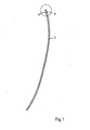
- Fig. 1 ein Ausführungsbeispiel des erfindungsgemäßen Knochennagels in Seitenansicht,
- Fig. la bis c das distale Ende eines Ausführungsbeispiels des erfindungsgemäßen Nagels in drei vergrößerten Seitenansichten,
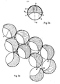
- Fig. 2a dasselbe Ausführungsbeispiel im Querschitt,
- Fig. 2b eine Anordnung mehrerer der in Fig. 2a dargestellten Nägel im Bündel,
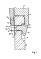
- Fig. 3 ein Werkzeug zum Ausüben einer Kraft bzw. eines Drehmoments auf einen derartigen Nagel im Schnitt sowie
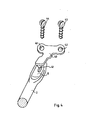
- Fig. 4 ein Fixationselement für einen Nagel gemäß der Erfindung.
- 1 shows an embodiment of the bone nail according to the invention in side view,
- La to c the distal end of an embodiment of the nail according to the invention in three enlarged side views,
- 2a the same embodiment in cross section,
- 2b an arrangement of several of the nails shown in Fig. 2a in a bundle,
- Fig. 3 shows a tool for exerting a force or a torque on such a nail in section and
- Fig. 4 shows a fixation element for a nail according to the invention.
In Figur 1 ist ein Nagel 2 dargestellt, wobei der von den Figuren la bis lc erfasste und vergrößert wiedergegebene Bereich..von einer gestrichelten Linie umgeben ist. Eine Aussparung 8 des Nagels 2 ist an der Innenseite der Krümmung des Nagels angeordnet. Diese Krümmung kann sich aus verschiedenen Biegungen und Abbiegungen zusammensetzen, welche über die Gesamtlänge des Nagels verteilt sind, so daß bei der Anwendung zur Fixierung von Oberschenkelhalsfrakturen das die Aussparung 8 tragende Nagelende mit seiner der Aussparung gegenüberliegenden Rückseite schonend auf der Kortikalis anliegt.A
Bei dem in den Figuren la bis c dargestellten distalen Ende des erfindungsgemäßen Nagels 2, das vergrößert wiedergegeben ist, ist eine halbrundförmige Ausnehmung 8, deren Verrundung in Richtung der Rundung der Nageloberfläche verläuft, - in Bezug auf dessen äußerstes Ende zurückversetzt - angeordnet. Die Ausnehmung 8 geht in ihren sich in Längsrichtung des Nagels erstreckenden Randbereichen in weichgeschwungener Formgebung in die Zylindermantelfläche des Nagels über. Auf dem Grunde der Ausnehmung ist eine Durchtrittsöffnung 9 vorgesehen, welche einen Durchlaß zum gegenüberliegenden Bereich der Mantelfläche des Nagels bildet und eine kleinere Fläche einnimmt als die Ausnehmung. Die Ausnehmung 8 weist eine obere Begrenzungsfläche 10 auf, die im wesentlichen horizontal verläuft. An diese gebildet ist und deren Fläche schließt direkt oder über eine Stufung der dem distalen Ende des Nagels nahegelegene Bereich der Durchtrittsöffnung 9 an. Zur Einleitung eines Drehmoments dienende Bereiche 11 und 12 sind seitlich der Ausnehmung 8 vorgesehen, welche vorzugsweise einseitig angebracht ist.In the distal end of the
In Figur 2a ist der in den Figuren 1 bis lc dargestellte Knochennagel im Querschnitt wiedergegeben. Die Schnittebene ist in Figur lb mit II gekennzeichnet. Die Aussparung 8 ist dabei durch Kaltverformung in der Weise erzeugt worden, daß die Bereiche 11 und 12 sich über den kreisförmigen Nagelquerschnitt hinaus erstrecken und symmetrisch in Bezug auf eine strichpunktiert dargestellte, einen Durchmesser markierende Linie 13 angeordnet sind. Die Bereiche 11 und 12, die sich vorwölben und in Längsrichtung des Nagels über eine Strecke in Längsrichtung des Nagels ihren Querschnitt nicht verändern bzw. eine maximale Außenkontur nicht überschreiten, sind weiterhin in dem über den Kreisquerschnitt des Nagels hinausragenden Bereich symmetrisch zu einer Linie 14 ausgebildet, welche ebenfalls strichpunktiert dargestellt ist, so daß der Zugriff durch ein Werkzeug ermöglicht ist, welches in seiner inneren Kontur durch eine gestrichelte Linie 15 angedeutet ist. Das Werkzeug läßt sich auf diese Weise leicht aufstecken und handhaben, was im übrigen auch durch eine (um 180°) drehsymmetrisch ausgebildete Anordnung der Bereiche 11 und 12 erzielbar ist.2a shows the cross section of the bone nail shown in FIGS. 1 to 1c. The section plane is marked II in FIG. 1b. The
Aus dieser Schnittdarstellung ist ersichtlich, daß der Querschnitt des Nagels im Bereich der Ausnehmung 8 eine geringfügige Abweichung von der Kreisscheibenform aufweist, wenn man einmal von der Ausnehmung 8 selbst und der Durchtrittsöffnung 9 absieht. Die Querschnittsform ist bevorzugt geringfügig elliptisch bzw. oval oder dreieckig verrundet ausgebildet, wobei im Falle elliptischer Gestaltung das Achsenverhältnis bevorzugt im Bereich zwischen 1 zu 1,1 und 1 zu 1,2 gewählt ist und die längere Halbachse parallel zu demjenigen Oberflächenbereich gerichtet ist, an der die Ausnehmung 8 vorgesehen ist. Eine derartige geringfügige exzentrische Verformung des Querschnitts des Nagelendes im Bereich der Ausnehmung 8 läßt sich entsprechend einem bevorzugten Herstellungsverfahren für den erfindungsgemäßen Nagel durch Einschlagen der Ausnehmung im Wege der Kaltverformung erzielen. Die sich ergebende Exzentrizität ist ausreichend, um beim Einschlagen des Nagels mittels einer entsprechend angepaßten, auf diesen aufzusetzenden Hülse ein Drehmoment aufzubringen, welches ein gesteuertes Führen des Nagels bezüglich der an seinem proximalen Ende einzuschlagenden Richtung ermöglicht.From this sectional view it can be seen that the cross section of the nail in the region of the
Es ist aus Figur 2a ferner ersichtlich, daß die Ausnehmung 8 derart angeordnet ist, daß sie aufgrund der erfindungsgemäßen Verrundungen in ihren seitlichen Bereichen keinerlei Kanten oder Flächen aufweist, welche einen meißelartigen Druck auf Knochen- oder Gewebeteile ausüben könnten. Eine derartige Einwirkung von eng begrenzten Flächenteilen mit dem daraus resultierenden hohen Anpreßdruck auf Knochen- oder Gewebebereiche ist auch dadurch verhindert, daß die Ausnehmung 8 nicht unmittelbar am Ende des Nagels, sondern um eine geringe Entfernung von dem Ende zurückversetzt angeordnet ist, so daß sich am unmittelbaren Nagelende ein im wesentlichen unverformter Bereich der Nageloberfläche befindet, der sich großflächig am Knochen bzw. Gewebe abstützen kann.It can also be seen from FIG. 2a that the
Die der Ausnehmung 8 gegenüberliegende Außenfläche des Nagels bildet einen Bereich, der auch bei axial um mehr als ±90* verdrehter Einbringung des Nagels eine sichere Anlage am oberen Rand eines Knochenfensters gewährleistet. Wegen der relativ geringfügigen Abweichung des Nagelendes vom Kreisquerschnitt ist eine Parallelanordnung der Nägel in Bündellage auch im Bereich der Ausnehmung 8 ohne merkbaren zusätzlichen Raumbedarf möglich.The outer surface of the nail opposite the
In Figur 2b ist eine Vielzahl von Nägeln 8 in willkürlicher bündelartiger Anordnung im Schnitt wiedergegeben, wobei an verschiedenen Berührungsbereichen benachbarter Nägel gezeigt werden soll, daß trotz der den Kreisquerschnitt der Nägel überschreitenden Bereiche 11 und 12 eine Nagelanordnung möglich ist, bei der der behandelnde Chirurg nicht darauf achten muß, eine genaue Ausrichtung der Nägel in bezug auf die Richtung der Ausnehmungen 8 zu erreichen. Vielmehr ist eine dichte Bündelpackung auch dann möglich, wenn die einzelnen Nägel um Winkelbeträge unterschiedlich angeordnet sind.In Figure 2b, a plurality of
Dabei erstrecken sich an den Orten von sich zwischen benachbarten, dicht angordneten Nägeln befindlichen Hohlräume 21 bis 25 die den Kreisquerschnitt überschreitenden Bereiche 11 und 12 der Nägel 2. Sie ragen in die nicht von Material ausgefüllten Räume zwischen den Kreisquerschnitten der Nägel hinein, so daß die Nägel in dichtester Packung angeordnet sein können. Im Bereich 22 sind in dem durch das Aneinandergrenzen von drei Nägeln verbleibenden Aussparungsbereich die Wölbungsbereiche zweier Nägel angeordnet, welche sich ebenfalls nicht behindern.The
Aus Figur 2b ist ersichtlich, daß das Anlehnen der distalen Nagelenden an der Kortikalis nicht entlang einer geraden Linie zu erfolgen braucht, sondern daß hier auch einer Krümmung ohne weiteres gefolgt werden kann. (Die Begrenzungslinie für den für die Nagelung zur Verfügung stehenden Raum kann dabei eine die in Figur 2b oben wiedergegebenen Nägel tangierende Linie gedacht werden.) Die dargestellten Vorteile der raumsparenden Anordnung bei dichter Bündelpackung beziehen sich auch auf die entsprechenden, im Bereich der entgegengesetzten Nagelenden (in den Zeichnungen nicht wiedergegebenen) Bereiche.It can be seen from FIG. 2b that the distal nail ends do not have to be leaned against the cortex along a straight line, but that a curvature can also be easily followed here. (The boundary line for which are available for nailing the space can be thought of as a line tangent to the nails shown in FIG. 2b above.) The illustrated advantages of the space-saving arrangement with a dense bundle also relate to the corresponding areas in the area of the opposite nail ends (not shown in the drawings).
Weiterhin soll darauf hingewiesen werden, daß der zwischen den Kreisquerschnitten der Nägel zur Verfügung stehende Raum auch dann von den vorgewölbten Bereichen 11 und 12 eingenommen werden kann, wenn die Aussparungen 8 sich nicht in der selben Höhe befinden.It should also be pointed out that the space available between the circular cross sections of the nails can also be occupied by the protruding
In Figur 3 ist der untere Bereich eines Werkzeugs 31 dargestellt, welches sich zur Ausübung von Druck- und Zugkräften bzw. Drehmomenten in Eingriff mit dem distalen Ende des Nagels 2 befindet. In der Figur sind mehrere Varianten gestrichelt wiedergegeben, welche in unterschiedlicher Kombination Anwendung finden könnnen.FIG. 3 shows the lower region of a
Ist das Ende des Nagels 2 im Bereich der Aussparung oval oder elliptisch ausgeführt, so wird zweckmäßig als Schlageisen ein Instrument verwendet, welches (abweichend von in Figur 3 dargestellten Form) eine an die unrunde Form des Nagelendes angepaßte Aussparung enthält und somit beim Einschlagen die zur Drehung des Nagels erforderlichen Momente übertragen kann.If the end of the
Andererseits lassen sich bei unrundem und auch bei kreisrundem Querschnitt sowohl zum drehenden Einschlagen als auch zum Zurückziehen des Nagels Werkzeuggestaltungen verwenden, wie sie in Figur 3 dargestellt sind.On the other hand, in the case of a non-circular and also a circular cross section, tool designs can be used, both for turning in and for withdrawing the nail, as are shown in FIG. 3.
An einem Trägerteil 32 des Werkzeugs 31 ist ein hakenförmiger Ansatz vorgesehen, welcher mit einem Backen 33 versehen ist, der an die Ausnehmung 8 angepaßt ist. Eine Fläche 34, welche auf die Fläche 10 des Nagels 2 einwirkt, ermöglicht dabei ein Zurückziehen des Nagels aus dem Knochen nach abgeschlossenem Heilerfolg.On a
Zur Führung des hakenförmigen Endes des Teils 32 des Werkzeugs 11 beim Ergreifen des distalen Endes des Nagels 2 dient ein Stift 35, der in verschiedener Länge (gestrichelte Linie 35a) vorgesehen sein kann und zur Erleichterung des Einführens in die Ausnehmung 9 an seinem freien Ende verrundet ausgebildet ist.To guide the hook-shaped end of
Um ein Abgleiten des hakenförmigen Ansatzes mit der Fläche 34 des Werkzeugs 31 beim Aufbringen eines Drehmoments oder beim Zurückziehen zu verhindern, ist an dem mit der Ausnehmung 8 in Kontakt kommenden Teil des Werkzeugs 31 eine Sperre 36 vorgesehen, welche verschiedenartig ausgebildet sein kann. Die als durchgezogene Linie dargestellte Variante kann in Form eines vom nicht dargestellten oberen Ende des Werkzeugs her betätigbaren und in Richtung des Nagels 2 verschiebbarer Riegel gestaltet oder aber den Gegenbacken einer Zange darstellen, mit der das distale Ende des Nagels 2 ergriffen werden kann.In order to prevent the hook-shaped attachment from sliding off with the
Andererseits ist auch eine (gestrichelt dargestellte) Variante möglich, die fest mit der gegenüberliegenden, in die Ausnehmung 8 eingreifenden Seite des Werkzeugs 31 verbunden, aber verkürzt und geringfügig verrundet ausgebildet ist, so daß das einstückig feststehend gestaltete Werkzeug 31 mit seitlicher Neigung dem Nagelende "übergestülpt" werden kann. Wird das Werkzeug koaxial zum Nagel geführt, ist ein Abrutschen des in die Ausnehmung 8 eingreifenden Teil 33 sicher verhindert.On the other hand, a variant (shown in dashed lines) is also possible, which is fixedly connected to the opposite side of the
Bei zangenförmiger Ausgestaltung des Werkzeugs 31 ist weiterhin eine Variante günstig, welche als strichpunktierte Linie 36b wiedergegeben ist, wobei diese verlängerte Ausführung mit einem Durchbruch 37 versehen ist, welcher mit dem verlängerten Stift 35a in Eingriff kommt, so daß in Fällen, bei denen zum Herausziehen des Nagels besonders große Kräfte aufzubringen sind, die Festigkeit der Verbindung Werkzeug/Nagel zusätzlich erhöht ist.In the case of pliers-shaped design of the
In Figur 4 ist ein Fixierungselement 40 in Verbindung mit einem Nagel 2 dargestellt, wobei das Fixierungselement eine Platte darstellt, welche mit einem nasenförmigen Ansatz 41 versehen ist, welche zum Eingriff in die Aussparung 8 des Nagels geformt ist. Durch die Verrundung der Nase 41 ist ein einfaches Einsetzen gewährleistet, wobei der sichere Eingriff im fixierten Zustand durch die von der Platte ausgeübte Anpresskraft gewährleistet ist. Dazu weist sie zwei runde Aussparungen 42 und 43 auf, in die Knochenschrauben 44 und 45 einbringbar sind, welche das Fixierungselement 40 festhalten. Zum Entfernen des Nagels kann das Fixierungselement 40 auf einfache Weise gelöst werden.FIG. 4 shows a fixing
Die Erfindung läßt über die dargestellten beispielhaften Ausführungsformen hinaus eine Vielzahl weiterer Varianten zu, wobei auch das Werkzeug zur Manipulation des Nagels und das Fixierungselement entsprechend vielfältig ausgebildet sein können.In addition to the exemplary embodiments shown, the invention permits a large number of further variants, including the tool for manipulating the nail and the fixing element can be designed in a correspondingly diverse manner.
Claims (12)
der vom runden Querschnitt abweichende Bereich
dadurch gekennzeichnet ,
wobei sich die Ausnehmung (8) bei gekrümmtem Nagel an der Innenseite der auf die Gesamtlänge des Nagels (2) bezogenen Krümmung befindet.1. Elastic nail (2) for fixing a thigh fracture with an area deviating from the round cross-section near one of its ends in order to introduce forces and / or moments when manipulating - preferably for use according to the principle of so-called "bundle nailing" with a curvature and Elasticity such that the nail driven into the medullary tube is supported with its distal end on the cortex - whereby
the area deviating from the round cross section
characterized ,
the recess (8) being located on the inside of the curvature related to the total length of the nail (2) when the nail is curved.
Priority Applications (1)
| Application Number | Priority Date | Filing Date | Title |
|---|---|---|---|
| AT82730083T ATE26915T1 (en) | 1981-06-18 | 1982-06-18 | NAIL FOR FIXING A THIGH FRACTURE. |
Applications Claiming Priority (4)
| Application Number | Priority Date | Filing Date | Title |
|---|---|---|---|
| DE19813124059 DE3124059A1 (en) | 1981-06-18 | 1981-06-18 | Nail for fixing fractures of the femur |
| DE3124059 | 1981-06-18 | ||
| DE19813127378 DE3127378A1 (en) | 1981-07-09 | 1981-07-09 | Nail for the fixation of femoral fractures |
| DE3127378 | 1981-07-09 |
Publications (3)
| Publication Number | Publication Date |
|---|---|
| EP0069048A2 true EP0069048A2 (en) | 1983-01-05 |
| EP0069048A3 EP0069048A3 (en) | 1983-08-03 |
| EP0069048B1 EP0069048B1 (en) | 1987-05-06 |
Family
ID=25793955
Family Applications (1)
| Application Number | Title | Priority Date | Filing Date |
|---|---|---|---|
| EP82730083A Expired EP0069048B1 (en) | 1981-06-18 | 1982-06-18 | Nail for fractured femur neck fixation |
Country Status (5)
| Country | Link |
|---|---|
| US (1) | US4506662A (en) |
| EP (1) | EP0069048B1 (en) |
| CA (1) | CA1178150A (en) |
| DE (1) | DE3276213D1 (en) |
| ES (1) | ES272906Y (en) |
Cited By (2)
| Publication number | Priority date | Publication date | Assignee | Title |
|---|---|---|---|---|
| EP0425472A1 (en) * | 1989-10-25 | 1991-05-02 | Hans Georg Dr. Ender | Bone nail and tool therefor |
| FR2706279A1 (en) * | 1993-06-18 | 1994-12-23 | Duhautois Bruno | Ancillary orthopaedic device |
Families Citing this family (53)
| Publication number | Priority date | Publication date | Assignee | Title |
|---|---|---|---|---|
| DE8214493U1 (en) * | 1982-05-18 | 1982-09-09 | Howmedica International, Inc. Zweigniederlassung Kiel, 2301 Schönkirchen | Bone nail for the treatment of fractures in the proximal thigh area |
| JPS6017708U (en) * | 1983-07-13 | 1985-02-06 | 宮田 敬三 | Metal fittings for intramedullary fixation of fractured long bones |
| US4944615A (en) * | 1986-04-07 | 1990-07-31 | Brother Kogyo Kabushiki Kaisha | Permanent magnet print head assembly with a square magnet |
| PL147580B1 (en) * | 1986-04-14 | 1989-06-30 | Plate for uniting epiphysis and diaphysis of broken bone | |
| US4913137A (en) * | 1988-02-09 | 1990-04-03 | Orthopedic Designs, Inc. | Intramedullary rod system |
| US4973332A (en) * | 1988-09-12 | 1990-11-27 | Hospital For Joint Diseases | Attachment for femur sliding screw plate |
| US5443466A (en) * | 1991-12-13 | 1995-08-22 | Shah; Mrugesh K. | Method and apparatus for treating fractures of a bone |
| US5429640A (en) * | 1992-11-27 | 1995-07-04 | Clemson University | Intramedullary rod for fracture fixation of femoral shaft independent of ipsilateral femoral neck fracture fixation |
| US5697934A (en) * | 1996-12-02 | 1997-12-16 | Huebner; Randall J. | Tension band wiring pin and method |
| US6730090B2 (en) | 2000-02-01 | 2004-05-04 | Hand Innovations, Inc. | Fixation device for metaphyseal long bone fractures |
| US7857838B2 (en) | 2003-03-27 | 2010-12-28 | Depuy Products, Inc. | Anatomical distal radius fracture fixation plate |
| US6893444B2 (en) * | 2000-02-01 | 2005-05-17 | Hand Innovations, Llc | Bone fracture fixation systems with both multidirectional and unidirectional stabilization pegs |
| US20060041260A1 (en) * | 2000-02-01 | 2006-02-23 | Orbay Jorge L | Fixation system with plate having holes with divergent axes and multidirectional fixators for use therethrough |
| US6706046B2 (en) * | 2000-02-01 | 2004-03-16 | Hand Innovations, Inc. | Intramedullary fixation device for metaphyseal long bone fractures and methods of using the same |
| US7695502B2 (en) | 2000-02-01 | 2010-04-13 | Depuy Products, Inc. | Bone stabilization system including plate having fixed-angle holes together with unidirectional locking screws and surgeon-directed locking screws |
| US6767351B2 (en) * | 2000-02-01 | 2004-07-27 | Hand Innovations, Inc. | Fixation system with multidirectional stabilization pegs |
| US20040153073A1 (en) * | 2000-02-01 | 2004-08-05 | Hand Innovations, Inc. | Orthopedic fixation system including plate element with threaded holes having divergent axes |
| US7282053B2 (en) * | 2003-03-27 | 2007-10-16 | Depuy Products, Inc. | Method of using fracture fixation plate for performing osteotomy |
| US6902565B2 (en) | 2001-02-21 | 2005-06-07 | Synthes (U.S.A.) | Occipital plate and system for spinal stabilization |
| US6872210B2 (en) | 2001-02-23 | 2005-03-29 | James P. Hearn | Sternum fixation device |
| US20060149257A1 (en) * | 2002-05-30 | 2006-07-06 | Orbay Jorge L | Fracture fixation device |
| US7938850B2 (en) | 2002-05-30 | 2011-05-10 | Depuy Products, Inc. | Nail plate |
| US20040111090A1 (en) * | 2002-10-03 | 2004-06-10 | The University Of North Carolina At Chapel Hill | Modification of percutaneous intrafocal plate system |
| US20050187551A1 (en) * | 2002-12-02 | 2005-08-25 | Orbay Jorge L. | Bone plate system with bone screws fixed by secondary compression |
| US7780664B2 (en) | 2002-12-10 | 2010-08-24 | Depuy Products, Inc. | Endosteal nail |
| US20040193155A1 (en) * | 2003-03-27 | 2004-09-30 | Hand Innovations, Inc. | Fracture fixation plate with particular plate hole and fastener engagement and methods of using the same |
| US7294130B2 (en) * | 2003-03-27 | 2007-11-13 | Depuy Products, Inc. | Distal radius fracture fixation plate having K-wire hole structured to fix a K-wire in one dimension relative to the plate |
| US7635381B2 (en) * | 2003-03-27 | 2009-12-22 | Depuy Products, Inc. | Anatomical distal radius fracture fixation plate with fixed-angle K-wire holes defining a three-dimensional surface |
| US7250053B2 (en) * | 2003-03-27 | 2007-07-31 | Depuy Products, Inc. | Low profile distal radius fracture fixation plate |
| US7635365B2 (en) * | 2003-08-28 | 2009-12-22 | Ellis Thomas J | Bone plates |
| US7852919B2 (en) * | 2003-09-07 | 2010-12-14 | Microsoft Corporation | Field start code for entry point frames with predicted first field |
| US20050107793A1 (en) * | 2003-11-14 | 2005-05-19 | Manderson Easton L. | Surgical intramedullary implant with improved locking for fixation of fractured bone segments |
| US8394130B2 (en) * | 2005-03-17 | 2013-03-12 | Biomet C.V. | Modular fracture fixation system |
| US8062296B2 (en) * | 2005-03-17 | 2011-11-22 | Depuy Products, Inc. | Modular fracture fixation plate system with multiple metaphyseal and diaphyseal plates |
| EP1827271B1 (en) * | 2004-12-23 | 2009-12-02 | Hans Ulrich Stäubli | Bone fixing device |
| WO2006081483A1 (en) * | 2005-01-28 | 2006-08-03 | Depuy Products, Inc. | Nail plate system |
| US7905909B2 (en) * | 2005-09-19 | 2011-03-15 | Depuy Products, Inc. | Bone stabilization system including multi-directional threaded fixation element |
| US20070083202A1 (en) * | 2005-09-20 | 2007-04-12 | Donald Eli Running | Intramedullary bone plate with sheath |
| US8029551B2 (en) * | 2006-01-10 | 2011-10-04 | Running Donald E | Fracture fixation plate with cover sheath |
| US7867261B2 (en) * | 2006-03-17 | 2011-01-11 | Depuy Products, Inc. | Bone plate with variable torsional stiffness at fixed angle holes |
| US7722611B2 (en) * | 2007-03-05 | 2010-05-25 | Depuy Products, Inc. | Method of treating a clavicle fracture |
| GB2450247B (en) * | 2007-06-15 | 2010-01-13 | Joel Gillard | Rib fixation with an intramedullary nail |
| WO2009064643A1 (en) * | 2007-11-13 | 2009-05-22 | Synthes (U.S.A) | Periprosthetic fracture repair |
| CN102176873A (en) * | 2008-10-15 | 2011-09-07 | 捷迈有限公司 | Intramedullary nail |
| US8568417B2 (en) | 2009-12-18 | 2013-10-29 | Charles River Engineering Solutions And Technologies, Llc | Articulating tool and methods of using |
| FR2956971B1 (en) | 2010-03-08 | 2012-03-02 | Memometal Technologies | PLATE OSTEOSYNTHESIS SYSTEM |
| FR2956972B1 (en) * | 2010-03-08 | 2012-12-28 | Memometal Technologies | ARTICULATED OSTEOSYNTHESIS PLATE |
| US8518042B2 (en) | 2010-10-19 | 2013-08-27 | Biomet Manufacturing, Llc | Orthopedic plate assembly for a distal radius having re-contouring features and method for using same |
| WO2012174258A2 (en) * | 2011-06-14 | 2012-12-20 | Amit Gupta | Intramedullary system for managing a bone fracture |
| JP6240076B2 (en) | 2011-09-30 | 2017-11-29 | アキュート・イノヴェーションズ・エルエルシー | Bone fixation system with opposing mounting parts |
| WO2013113015A1 (en) | 2012-01-26 | 2013-08-01 | Acute Innovations Llc | Clip for rib stabilization |
| US9681902B2 (en) | 2012-02-13 | 2017-06-20 | Stryker European Holdings I, Llc | Attachment device for a bone plate |
| US10881436B2 (en) | 2017-10-27 | 2021-01-05 | Wright Medical Technology, Inc. | Implant with intramedullary portion and offset extramedullary portion |
Citations (3)
| Publication number | Priority date | Publication date | Assignee | Title |
|---|---|---|---|---|
| DE874637C (en) * | 1951-05-18 | 1953-04-27 | Reinhold Dipl-Ing Bock | Pull hook for pulling devices for removing nails surgically driven into bones |
| DE2527460A1 (en) * | 1975-06-20 | 1977-01-13 | Rayer Kg Karl | Curved bone pin aligning thighbone parts - with flattened disc at distal end projecting out of bone |
| US4055172A (en) * | 1973-07-18 | 1977-10-25 | Josef Ender | Nail and set for correctly resetting fractured bones for their immediate re-use |
Family Cites Families (3)
| Publication number | Priority date | Publication date | Assignee | Title |
|---|---|---|---|---|
| DE7417700U (en) * | 1974-05-21 | 1974-08-29 | Ulrich M | Intramedullary NAIL FOR SURGICAL FIXATION OF THIGH NECK FRACTURES |
| DE7519605U (en) * | 1975-06-20 | 1976-02-05 | Karl Rayer Kg, 7300 Esslingen | Curved bone nail |
| FR2484242A1 (en) * | 1980-03-14 | 1981-12-18 | Timoteo Michel | Osteosynthesis plate for supporting flexible pin - has pair of apertured feet at one end to receive fixing pin, toothed central section and flattened, rounded area at other end |
-
1982
- 1982-06-17 ES ES1982272906U patent/ES272906Y/en not_active Expired
- 1982-06-17 CA CA000405345A patent/CA1178150A/en not_active Expired
- 1982-06-18 US US06/390,079 patent/US4506662A/en not_active Expired - Fee Related
- 1982-06-18 DE DE8282730083T patent/DE3276213D1/en not_active Expired
- 1982-06-18 EP EP82730083A patent/EP0069048B1/en not_active Expired
Patent Citations (3)
| Publication number | Priority date | Publication date | Assignee | Title |
|---|---|---|---|---|
| DE874637C (en) * | 1951-05-18 | 1953-04-27 | Reinhold Dipl-Ing Bock | Pull hook for pulling devices for removing nails surgically driven into bones |
| US4055172A (en) * | 1973-07-18 | 1977-10-25 | Josef Ender | Nail and set for correctly resetting fractured bones for their immediate re-use |
| DE2527460A1 (en) * | 1975-06-20 | 1977-01-13 | Rayer Kg Karl | Curved bone pin aligning thighbone parts - with flattened disc at distal end projecting out of bone |
Non-Patent Citations (1)
| Title |
|---|
| BIOMEDIZINISCHE TECHNIK, Band 26, Nr. 11, November 1981, Seiten 283-285, Berlin, DE; C. KRANZ: "Vergleichende experimentelle Untersuchung von neu entwickelten Condylennagelenden". * |
Cited By (2)
| Publication number | Priority date | Publication date | Assignee | Title |
|---|---|---|---|---|
| EP0425472A1 (en) * | 1989-10-25 | 1991-05-02 | Hans Georg Dr. Ender | Bone nail and tool therefor |
| FR2706279A1 (en) * | 1993-06-18 | 1994-12-23 | Duhautois Bruno | Ancillary orthopaedic device |
Also Published As
| Publication number | Publication date |
|---|---|
| ES272906U (en) | 1984-05-16 |
| CA1178150A (en) | 1984-11-20 |
| DE3276213D1 (en) | 1987-06-11 |
| ES272906Y (en) | 1984-12-16 |
| US4506662A (en) | 1985-03-26 |
| EP0069048B1 (en) | 1987-05-06 |
| EP0069048A3 (en) | 1983-08-03 |
Similar Documents
| Publication | Publication Date | Title |
|---|---|---|
| EP0069048B1 (en) | Nail for fractured femur neck fixation | |
| DE4318150C2 (en) | Osteosynthesis tools for the treatment of subtrochanteric and pertrochanteric fractures as well as fractures of the femoral neck | |
| DE60006737T2 (en) | Bone clamp for dynamic and non-dynamic fracture compression | |
| EP0641547B1 (en) | Implantation system for vertebral fusion | |
| EP2621383B1 (en) | Bilateral lamina implant | |
| DE102015008036A1 (en) | Pedicle screw with tulip | |
| EP0236698A2 (en) | Screwdriver for surgery | |
| DE2716403A1 (en) | DEVICE FOR SETTING BONE BREAKS | |
| EP0625340A2 (en) | Sleeve for healing promotion of bone defects | |
| EP0094489A2 (en) | Bone nail for the treatment of fractures of the proximal part of the femur, and the appropriate tools | |
| EP0613657A1 (en) | Fixation pin and driving tool | |
| DE2609723A1 (en) | BONE NAIL | |
| WO2005092225A1 (en) | Resetting tool | |
| DE3916198A1 (en) | Anchoring element for spinal column support - incorporates U=shaped slot to receive shaft to support | |
| AT509852B1 (en) | FLEXIBLE HUMERUS NAIL | |
| EP2859855A1 (en) | Repositioning pliers with dual 90° deformation for distribution on two levels | |
| CH631338A5 (en) | Thigh and lower leg locking nail | |
| DE2260839C2 (en) | Device for the treatment of separated long bones by means of pressure osteosynthesis | |
| EP3136990A1 (en) | Jaw for a surgical tubular shaft instrument | |
| DE3124059A1 (en) | Nail for fixing fractures of the femur | |
| DE19703987C1 (en) | Target device for an implant to treat trochanteric and subtrochanteric fractures | |
| EP0539536A1 (en) | Screw unit. | |
| WO2002080790A1 (en) | Bone nail for surgical purposes | |
| DE102006036117B4 (en) | Surgical instrument for spreading two mutually adjacent surgical openings | |
| DE19615103A1 (en) | Bone marrow nail |
Legal Events
| Date | Code | Title | Description |
|---|---|---|---|
| PUAI | Public reference made under article 153(3) epc to a published international application that has entered the european phase |
Free format text: ORIGINAL CODE: 0009012 |
|
| AK | Designated contracting states |
Designated state(s): AT BE CH DE FR GB IT LI NL SE |
|
| PUAL | Search report despatched |
Free format text: ORIGINAL CODE: 0009013 |
|
| AK | Designated contracting states |
Designated state(s): AT BE CH DE FR GB IT LI NL SE |
|
| 17P | Request for examination filed |
Effective date: 19840124 |
|
| ITF | It: translation for a ep patent filed |
Owner name: BARZANO' E ZANARDO MILANO S.P.A. |
|
| GRAA | (expected) grant |
Free format text: ORIGINAL CODE: 0009210 |
|
| AK | Designated contracting states |
Kind code of ref document: B1 Designated state(s): AT BE CH DE FR GB IT LI NL SE |
|
| PG25 | Lapsed in a contracting state [announced via postgrant information from national office to epo] |
Ref country code: NL Effective date: 19870506 |
|
| REF | Corresponds to: |
Ref document number: 26915 Country of ref document: AT Date of ref document: 19870515 Kind code of ref document: T |
|
| REF | Corresponds to: |
Ref document number: 3276213 Country of ref document: DE Date of ref document: 19870611 |
|
| ET | Fr: translation filed | ||
| NLV1 | Nl: lapsed or annulled due to failure to fulfill the requirements of art. 29p and 29m of the patents act | ||
| PLBE | No opposition filed within time limit |
Free format text: ORIGINAL CODE: 0009261 |
|
| STAA | Information on the status of an ep patent application or granted ep patent |
Free format text: STATUS: NO OPPOSITION FILED WITHIN TIME LIMIT |
|
| 26N | No opposition filed | ||
| ITTA | It: last paid annual fee | ||
| ITPR | It: changes in ownership of a european patent |
Owner name: CAMBIO SEDE;MECRON MEDIZINISCHE PRODUKTE GMBH |
|
| REG | Reference to a national code |
Ref country code: CH Ref legal event code: PFA Free format text: JOHNSON & JOHNSON PROFESSIONAL PRODUCTS GMBH |
|
| REG | Reference to a national code |
Ref country code: FR Ref legal event code: CD Ref country code: FR Ref legal event code: CA |
|
| EAL | Se: european patent in force in sweden |
Ref document number: 82730083.1 |
|
| REG | Reference to a national code |
Ref country code: CH Ref legal event code: PUE Owner name: JOHNSON & JOHNSON PROFESSIONAL PRODUCTS GMBH -DANN |
|
| BECA | Be: change of holder's address |
Free format text: 960917 *JOHNSON & JOHNSON MEDICAL G.M.B.H.:OSTDTR. 1, D-22844 NORDERSTEDT |
|
| BECH | Be: change of holder |
Free format text: 960917 *JOHNSON & JOHNSON MEDICAL G.M.B.H.:OSTDTR. 1, D-22844 NORDERSTEDT |
|
| REG | Reference to a national code |
Ref country code: GB Ref legal event code: 732E |
|
| PGFP | Annual fee paid to national office [announced via postgrant information from national office to epo] |
Ref country code: GB Payment date: 19970609 Year of fee payment: 16 |
|
| PGFP | Annual fee paid to national office [announced via postgrant information from national office to epo] |
Ref country code: FR Payment date: 19970610 Year of fee payment: 16 |
|
| PGFP | Annual fee paid to national office [announced via postgrant information from national office to epo] |
Ref country code: AT Payment date: 19970611 Year of fee payment: 16 |
|
| PGFP | Annual fee paid to national office [announced via postgrant information from national office to epo] |
Ref country code: SE Payment date: 19970618 Year of fee payment: 16 |
|
| PGFP | Annual fee paid to national office [announced via postgrant information from national office to epo] |
Ref country code: DE Payment date: 19970630 Year of fee payment: 16 Ref country code: CH Payment date: 19970630 Year of fee payment: 16 |
|
| PGFP | Annual fee paid to national office [announced via postgrant information from national office to epo] |
Ref country code: BE Payment date: 19970812 Year of fee payment: 16 |
|
| PG25 | Lapsed in a contracting state [announced via postgrant information from national office to epo] |
Ref country code: GB Free format text: LAPSE BECAUSE OF NON-PAYMENT OF DUE FEES Effective date: 19980618 Ref country code: AT Free format text: LAPSE BECAUSE OF NON-PAYMENT OF DUE FEES Effective date: 19980618 |
|
| PG25 | Lapsed in a contracting state [announced via postgrant information from national office to epo] |
Ref country code: SE Free format text: LAPSE BECAUSE OF NON-PAYMENT OF DUE FEES Effective date: 19980619 |
|
| PG25 | Lapsed in a contracting state [announced via postgrant information from national office to epo] |
Ref country code: LI Free format text: LAPSE BECAUSE OF NON-PAYMENT OF DUE FEES Effective date: 19980630 Ref country code: CH Free format text: LAPSE BECAUSE OF NON-PAYMENT OF DUE FEES Effective date: 19980630 Ref country code: BE Free format text: LAPSE BECAUSE OF NON-PAYMENT OF DUE FEES Effective date: 19980630 |
|
| BERE | Be: lapsed |
Owner name: JOHNSON & JOHNSON MEDICAL G.M.B.H. Effective date: 19980630 |
|
| GBPC | Gb: european patent ceased through non-payment of renewal fee |
Effective date: 19980618 |
|
| REG | Reference to a national code |
Ref country code: CH Ref legal event code: PL |
|
| PG25 | Lapsed in a contracting state [announced via postgrant information from national office to epo] |
Ref country code: FR Free format text: LAPSE BECAUSE OF NON-PAYMENT OF DUE FEES Effective date: 19990226 |
|
| EUG | Se: european patent has lapsed |
Ref document number: 82730083.1 |
|
| PG25 | Lapsed in a contracting state [announced via postgrant information from national office to epo] |
Ref country code: DE Free format text: LAPSE BECAUSE OF NON-PAYMENT OF DUE FEES Effective date: 19990401 |
|
| REG | Reference to a national code |
Ref country code: FR Ref legal event code: ST |