EP0056877A1 - Oral care apparatus - Google Patents
Oral care apparatus Download PDFInfo
- Publication number
- EP0056877A1 EP0056877A1 EP19810200071 EP81200071A EP0056877A1 EP 0056877 A1 EP0056877 A1 EP 0056877A1 EP 19810200071 EP19810200071 EP 19810200071 EP 81200071 A EP81200071 A EP 81200071A EP 0056877 A1 EP0056877 A1 EP 0056877A1
- Authority
- EP
- European Patent Office
- Prior art keywords
- housing
- light source
- switch
- toothbrush
- dichroic filter
- Prior art date
- Legal status (The legal status is an assumption and is not a legal conclusion. Google has not performed a legal analysis and makes no representation as to the accuracy of the status listed.)
- Granted
Links
Images

Classifications
-
- A—HUMAN NECESSITIES
- A61—MEDICAL OR VETERINARY SCIENCE; HYGIENE
- A61B—DIAGNOSIS; SURGERY; IDENTIFICATION
- A61B5/00—Measuring for diagnostic purposes; Identification of persons
- A61B5/0059—Measuring for diagnostic purposes; Identification of persons using light, e.g. diagnosis by transillumination, diascopy, fluorescence
- A61B5/0082—Measuring for diagnostic purposes; Identification of persons using light, e.g. diagnosis by transillumination, diascopy, fluorescence adapted for particular medical purposes
- A61B5/0088—Measuring for diagnostic purposes; Identification of persons using light, e.g. diagnosis by transillumination, diascopy, fluorescence adapted for particular medical purposes for oral or dental tissue
-
- A—HUMAN NECESSITIES
- A46—BRUSHWARE
- A46B—BRUSHES
- A46B15/00—Other brushes; Brushes with additional arrangements
- A46B15/0002—Arrangements for enhancing monitoring or controlling the brushing process
-
- A—HUMAN NECESSITIES
- A46—BRUSHWARE
- A46B—BRUSHES
- A46B15/00—Other brushes; Brushes with additional arrangements
- A46B15/0002—Arrangements for enhancing monitoring or controlling the brushing process
- A46B15/0016—Arrangements for enhancing monitoring or controlling the brushing process with enhancing means
- A46B15/0036—Arrangements for enhancing monitoring or controlling the brushing process with enhancing means with a lighting means, e.g. laser, bulb
-
- A—HUMAN NECESSITIES
- A46—BRUSHWARE
- A46B—BRUSHES
- A46B2200/00—Brushes characterized by their functions, uses or applications
- A46B2200/10—For human or animal care
- A46B2200/1066—Toothbrush for cleaning the teeth or dentures
Definitions
- the present invention relates to an apparatus for oral care comprising a handle-box, for example elongated, intended to fix a toothbrush and in which is mounted a toothbrush drive motor.
- toothbrushes have been known for many years and their use has now entered the customs, their efficiency and their maneuverability constituting their main asset.
- the most common toothbrushes include an elongated handle housing in which is mounted the electric motor intended to drive, for example with an oscillating movement, a shaft which projects at the end of the housing and on which the rod is fixed interchangeable toothbrushes.
- dental plaque is a film, normally invisible, which is formed on the teeth made up in particular of bacteria, and it constitutes one of the main factors of the deterioration of the teeth, this is why it is important to regularly check the state of the mouth in order to detect the presence of this plaque .
- the most used method to make this dental plaque visible is to coat the areas to be tested with a fluorescent solution and excite this solution by means of lamps emitting a light spectrum which responds to the fluorescent solution.
- the fluorescent material has been shown to adhere only to the parts of the teeth covered by this plaque, but not to the clean, healthy parts. It has also been found that this fluorescent material also adheres to the scaled parts, the tartar being formed by mineralization of the plaque, on the parts attacked by dental caries and even on the affected parts of the gums.
- the present invention proposes to provide a combined device which advantageously reduces the number of accessories necessary for rigorous dental hygiene.
- the device is characterized in that it is combined with a device used to test the condition of the mouth parts by excitation of a fluorescent material applied to the part to be tested, part of the wall of the housing. being provided with a transparent zone behind which is mounted a light source actuable by a switch.
- toothbrush is generally suspended on a suitable support in the bathroom, the user always has it at hand, so he will have the test lamp at the same time, which will encourage him to check more often the condition of his mouth.
- This ingenious combination toothbrush and test lamp can be produced for practically the same price as a simple electric toothbrush, which is advantageous for the consumer and saves him the expense of a special independent lamp.
- the device is also equipped with a container, either removable or incorporated into the housing, to contain the fluorescent material.
- the apparatus comprises an elongated handle-housing 1 at the front end of which protrudes, in the known manner, a shaft 2 intended to be driven in an oscillating movement by an electric motor 3 incorporated in the housing 1. On this shaft 2 is mounts the rod 4 of the interchangeable toothbrushes.
- the rear end 5 of the housing 1 has a flared shape and ends in a flange 5a on which the device can bear when it is placed on a flat support. A distance from the end of this rim 5a is mounted a dichroic filter 6 which is, for example, retained between a shoulder 5b of the side wall of the housing and a ring 14.
- This dichroic filter 6 which is in this way set back and therefore protected by the rim 5a, allows the light rays to pass, of selected wavelengths coming from an incandescent bulb 7 fixed in a recess 13 of the housing 1 and directed towards the filter.
- This filter 6 is matched with the fluorescent material used to essentially transmit the rays coming from the light source necessary for fluorescent excitation and essentially absorb the range of the spectrum corresponding to fluorescent light.
- the rear part 5 of the device can be separated from the main part 1, and it is for this purpose for example screwed onto said housing.
- Another solution is to simply have the removable ring 14.
- the electric motor 3 and the bulb 7 are supplied by the sector by means of an electric cord 8 and a single switch 9, placed on the side wall of the housing 1, makes it possible to control the switching on and off either the toothbrush or the incandescent bulb 7.
- the switch 9 is arranged in a window 10 in the side wall of the housing 1 so that in the central position shown, it is in the rest position, so neither the bulb nor the brush are actuated, only in the limit position to the left of the drawing according to arrow F1, it is the toothbrush which is actuated and in the limit position towards the right of the drawing, according to arrow F2, the incandescent bulb 7 is switched on and the device can be used for the light test.
- the switches 11 and 12 are separated from each other, the switch of the toothbrush 11 being at the end of the housing directed towards the brush 4 while the bulb switch 7 is located at the rear end.
- the electric motor 3 and the bulb 7 are supplied by the sector, preferably via a transformer, but the device can naturally be designed to operate by battery, rechargeable or not, one or more batteries being then stored in an appropriate recess of the housing or on a support external to the housing. It is also conceivable that the bulb alone is powered by a battery while the electric motor runs on the sector.
- the position of the bulb 7 and the dichroic filter 6 is of course not limited to the bottom of the housing, although this location seems to be the most practical so that the light can be effectively directed towards the buccal parts to be tested. Any other part of the side wall of the housing 1 can be provided with this filter 6. Furthermore, a dichroic reflector, not shown, can be mounted behind the bulb in order to amplify the radiation thereof.
- a light source emitting only short wavelengths could be provided and the radiation could be at least approximately monochromatic.
- the most suitable light source for this purpose is that provided by light or light emitting diodes and the bulb could therefore be replaced by one or more light diodes arranged side by side.
- end of the rear part 5 of the housing could have another shape than flared, for example simply cylindrical.
- FIG. 3 is also shown schematically and in broken lines another variant of the apparatus, namely its combination with a container 35 containing the fluorescent material, for example fluorescein.
- This container 35 is formed with a wall which adapts to the cylindrical shape of the housing 1 and is fixed removably on the said housing by a clip 38. It is also provided with an outlet tube 36 which can be tilted according to arrow A around d 'an axis 37 and which, in the retracted position, closes the opening of the container, as described in Swiss patent No 598 801 of the applicant.
- the outer wall 39 is semi-rigid over all or part of its surface so that the user can extract the material from the container by simple pressure on this wall.
- the housing 15 has a generally ovoid general shape, but with truncated ends, and it can be placed on a support, when not in use, resting on its flat underside formed by a flange annular 16.
- the dichroic filter 17 is mounted in the bottom of the housing 15, at a distance from the annular rim 16 so as not to touch the bearing surface on which the device is placed.
- the filter 17 is fixed between a shoulder 33 on the side wall of the housing and a retaining ring 34, it is in this way removable to make the bulb 18 accessible.
- the light source consists of an incandescent bulb cence 18 or light-emitting diodes.
- the light source switch consists of a spring contact 19 mounted in the bottom of the housing and slightly protruding from the level of the bottom in the closed state. This contact is designed so as to cut off the lamp supply circuit 18 when the appliance is in the rest position, pressing on a support, and to close the circuit, ---- therefore switch on the bulb, when the device is removed from its support. So with this embodiment, the lamp turns on automatically as soon as the user takes the device in hand.
- Another switch 20 is provided for controlling the motor of the toothbrush 21, this switch being preferably located on the side wall of the housing.
- this invention can in principle also be applied to a toothbrush driven by a hydraulic motor, in this case the light source is powered by a battery. Furthermore, this invention is also applicable to a combined apparatus which is not only suitable for driving a toothbrush, but for feeding a spray nozzle attached to the head.
- FIG 5 is illustrated, by way of example, an alternative embodiment of the apparatus with the filter 22 and the bulb 23 mounted on the side wall of the housing 24.
- the housing 24 has a shape general ovoid with truncated ends and the axis of the rod of the toothbrush 25 is not confused with the axis of the housing 24, but forms an angle with respect to it.
- the dichroic filter 22 is mounted in the lower part of the side wall of the housing 24 and the bulb 23 is mounted, in the housing, at a distance from this filter.
- a switch 26 also placed on the side wall of the housing, makes it possible to control either the operation of the toothbrush, or the energization of the bulb 23.
- the toothbrush motor is powered by a rechargeable battery
- the bottom of the housing 24 is provided with a projection 27 in which the inductive coupling is mounted for recharging, this projection being provided to be inserted in the recess 29 of a support 28, in which is mounted the primary winding of the transformer used to recharge the battery, this support being able to be connected to the network by a conductor 30.
- FIG. 5 is also shown another alternative embodiment, namely that a mirror 31 is also provided, also mounted on the side wall of the housing, and tiltable around an axis 32 situated next to the dichroic filter 22, the reflecting face of the mirror being situated towards the inside of the housing when said mirror is in its retracted position in which it covers and protects the filter; the position of use of the filter is indicated in phantom in Figure 5.
- a container 40 incorporated in the housing 15, intended to contain the fluorescent material.
- An outlet tube 41 tiltable around an axis 42 allowing in the folded or retracted position, to plug the outlet orifice of the container and in the unfolded position to release it.
- the outer wall 43 of the container 40 is, as in the previous embodiment, semi-rigid, to allow the extraction of the product.
Abstract
Description
La présente invention a pour objet un appareil pour soins buccaux comprenant un boîtier-poignée, par exemple allongé, destiné à fixer une brosse à dents et dans lequel est monté un moteur d'entraînement de la brosse à dents.The present invention relates to an apparatus for oral care comprising a handle-box, for example elongated, intended to fix a toothbrush and in which is mounted a toothbrush drive motor.
Les brosses à dents électriques sont connues depuis de nombreuses années et leur utilisation est maintenant entrée dans le moeurs, leur efficacité et leur maniabilité constituant leur atout principal. Les brosses à dents les plus courantes comportent un boîtier-poignée allongé dans lequel est monté le moteur électrique destiné à entraîner, par exemple d'un mouvement oscillant, un arbre qui fait saillie à l'extrémité du boîtier et sur lequel se fixe la tige des brosses à dents interchangeables.Electric toothbrushes have been known for many years and their use has now entered the customs, their efficiency and their maneuverability constituting their main asset. The most common toothbrushes include an elongated handle housing in which is mounted the electric motor intended to drive, for example with an oscillating movement, a shaft which projects at the end of the housing and on which the rod is fixed interchangeable toothbrushes.
Il est également connu depuis quelques temps des appareils ou dispositifs qui permettent à tout à chacun de tester à la maison ses dents et ses gencives, afin de vérifier si elles sont recouvertes de plaque dentaire. Comme on le sait depuis quelques années, la plaque dentaire est une pellicule, normalement invisible, qui se forme sur les dents composée en particulier de bactéries, et elle constitue l'un des principaux facteurs de la détérioration des dents, c'est pourquoi il est important de vérifier régulièrement l'état de la bouche afin de détecter la présence de cette plaque. Le procédé le plus utilisé pour rendre cette plaque dentaire visible est d'enduire les zones à tester avec une solution fluorescente et exciter cette solution au moyen de lampes émettant un spectre lumineux qui répond à la solution fluorescente. Il a été démontré que le matériau fluorescent adhérait seulement sur les parties des dents recouvertes par cette plaque, mais non sur les parties propres et saines. Il a également été constaté que ce matériau fluorescent adhérait aussi sur les parties entartrées, le tartre étant formé par une minéralisation de la plaque, sur les parties attaquées par la carie dentaire et même sur les parties affectées des gencives.It has also been known for some time devices or devices that allow everyone to test at home their teeth and gums, to check if they are covered with dental plaque. As we have known for a few years, dental plaque is a film, normally invisible, which is formed on the teeth made up in particular of bacteria, and it constitutes one of the main factors of the deterioration of the teeth, this is why it is important to regularly check the state of the mouth in order to detect the presence of this plaque . The most used method to make this dental plaque visible is to coat the areas to be tested with a fluorescent solution and excite this solution by means of lamps emitting a light spectrum which responds to the fluorescent solution. The fluorescent material has been shown to adhere only to the parts of the teeth covered by this plaque, but not to the clean, healthy parts. It has also been found that this fluorescent material also adheres to the scaled parts, the tartar being formed by mineralization of the plaque, on the parts attacked by dental caries and even on the affected parts of the gums.
Ainsi en appliquant une couche de matériau fluorescent sur les dents et les gencives, et en excitant ce matériau à l'aide d'une lampe appropriée, chaque particulier peut tester l'état de sa bouche.Thus by applying a layer of fluorescent material to the teeth and gums, and by exciting this material with the aid of an appropriate lamp, each individual can test the condition of his mouth.
Différents dispositifs ont été proposés pour mettre en évidence cette plaque dentaire, notamment le dispositif décrit dans le brevet suisse du déposant No 598 801 comprenant une lampe-test montée dans un boîtier, alimentée par une pile, un distributeur de produit fluorescent assemblé au boîtier, un filtre adapté à la solution fluorescente utilisée de façon à faire transmettre essentiellement les longueurs d'onde de la lumière nécessaires à l'excitation fluorescente et absorber essentiellement la gamme du spectre correspondant à la lumière fluorescente. Une lampe de poche simple peut également convenir à condition de la munir également d'un filtre approprié. Donc si un consommateur veut suivre une hygiène dentaire rigoureuse il doit avoir sous la main, dans sa salle de bains, d'une part la brosse à dents électrique qui lui assure un nettoyage efficace des dents et d'autre part le matériel pour tester l'état de sa bouche : matériau fluorescent et lampe-test. Ceci représente beaucoup d'accessoires qui encombrent la salle de bains et d'autre part risquent de s'égarer.Various devices have been proposed to highlight this dental plaque, in particular the device described in the applicant's Swiss patent No 598 801 comprising a test lamp mounted in a housing, powered by a battery, a fluorescent product distributor assembled in the housing, a filter adapted to the fluorescent solution used so as to transmit essentially the wavelengths of light necessary for fluorescent excitation and essentially absorb the range of the spectrum corresponding to fluorescent light. A simple flashlight may also be suitable provided that it also has an appropriate filter. So if a consumer teur wants to follow a strict dental hygiene he must have on hand, in his bathroom, on the one hand the electric toothbrush which ensures him an effective cleaning of the teeth and on the other hand the material to test the state of his mouth: fluorescent material and test lamp. This represents a lot of accessories that clutter the bathroom and on the other hand may get lost.
La présente invention se propose de réaliser un appareil combiné qui permet de diminuer avantageusement le nombre d'accessoires nécessaires à une hygiène dentaire rigoureuse.The present invention proposes to provide a combined device which advantageously reduces the number of accessories necessary for rigorous dental hygiene.
A cet effet, l'appareil est caractérisé par le fait qu'il est combiné à un dispositif servant à tester l'état des parties buccales par excitation d'un matériau fluorescent appliqué sur la partie à tester, une partie de la paroi du boîtier étant munie d'une zone transparente derrière laquelle est montée une source de lumière actionnable par un interrupteur.To this end, the device is characterized in that it is combined with a device used to test the condition of the mouth parts by excitation of a fluorescent material applied to the part to be tested, part of the wall of the housing. being provided with a transparent zone behind which is mounted a light source actuable by a switch.
La brosse à dents étant généralement suspendue à un support approprié dans la salle de bains, l'utilisateur l'a toujours à portée de main, il aura donc en même temps sous la main la lampe-test, ce qui l'incitera à vérifier plus souvent l'état de sa bouche. Cette combinaison ingénieuse : brosse à dents et lampe-test peut être fabriquée pratiquement pour le même prix qu'une brosse à dents électrique simple, ce qui est avantageux pour le consommateur et lui permet d'éviter les frais d'une lampe spéciale indépendante.The toothbrush is generally suspended on a suitable support in the bathroom, the user always has it at hand, so he will have the test lamp at the same time, which will encourage him to check more often the condition of his mouth. This ingenious combination: toothbrush and test lamp can be produced for practically the same price as a simple electric toothbrush, which is advantageous for the consumer and saves him the expense of a special independent lamp.
Préférablement, l'appareil est également équipé d'un récipient soit amovible, soit incorporé au boîtier, pour contenir le matériau fluorescent.Preferably, the device is also equipped with a container, either removable or incorporated into the housing, to contain the fluorescent material.
Des formes d'exécution préférées de l'invention résultent des autres revendications.Preferred embodiments of the invention result from the other claims.
La présente invention va maintenant être décrite, à titre d'exemple, en référence aux dessins annexés dans lesquels :
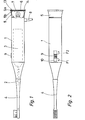
- la figure 1 est une vue en élévation d'une brosse à dents selon l'invention avec coupe partielle de l'extrémité postérieure du boîtier.
- La figure 2 en est une vue de dessus, montrant la face munie de l'interrupteur.
- La figure 3 est une vue d'une variante d'exécution des interrupteurs de l'appareil avec, en traits mixtes, un récipient amovible destiné à contenir le matériau fluorescent.
- La figure 4 est une variante d'exécution de l'appareil.
- La figure 5 représente une autre variante d'exécution de l'appareil avec le filtre dichroîque placé sur la paroi latérale du boîtier.
- Figure 1 is an elevational view of a toothbrush according to the invention with partial section of the rear end of the housing.
- Figure 2 is a top view showing the face provided with the switch.
- Figure 3 is a view of an alternative embodiment of the switches of the device with, in phantom, a removable container intended to contain the fluorescent material.
- Figure 4 is an alternative embodiment of the device.
- Figure 5 shows another alternative embodiment of the device with the dichroic filter placed on the side wall of the housing.
L'appareil comprend un boîtier-poignée allongé 1 à l'extrémité antérieure duquel dépasse, de la manière connue, un arbre 2 prévu pour être entraîné selon un mouvement oscillant par un moteur électrique 3 incorporé dans le boîtier 1. Sur cet arbre 2 se monte la tige 4 des brosses à dents interchangeables. L'extrémité postérieure 5 du boîtier 1 a une forme évasée et se termine par un rebord 5a sur lequel l'appareil peut prendre appui lorsqu'il est posé sur un support plan. A distance de l'extrémité de ce rebord 5a est monté un filtre dichroïque 6 qui est, par exemple, retenu entre un épaulement 5b de la paroi latérale du boîtier et un anneau 14. Ce filtre dichroique 6, qui est de cette manière en retrait et donc protégé par le rebord 5a, permet de laisser passer les rayons lumineux, de longueurs d'ondes choisies venant d'une ampoule incandescente 7 fixée dans un évidement 13 du boîtier 1 et dirigée vers le filtre. Ce filtre 6 est assorti au matériau fluorescent utilisé pour transmettre essentiellement les rayons provenant de la source de lumière nécessaires à l'excitation fluorescente et absorber essentiellement la gamme du spectre correspondant à la lumière fluorescente.The apparatus comprises an elongated handle-
Pour remplacer l'ampoule 7, la partie postérieure 5 de l'appareil peut être séparée de la partie principale 1, et elle est à cet effet par exemple vissée sur ledit boîtier. Une autre solution consiste d'avoir simplement l'anneau 14 amovible.To replace the
Sur la forme d'exécution représentée, le moteur électrique 3 ainsi que l'ampoule 7 sont alimentés par le secteur au moyen d'un cordon électrique 8 et un interrupteur unique 9, placé sur la paroi latérale du boîtier 1, permet de commander la mise en marche et l'arrêt soit de la brosse à dents soit de l'ampoule incandescente 7. L'interrupteur 9 est disposé dans une fenêtre 10 de la paroi latérale du boîtier 1 de telle façon que dans la position centrale représentée, il se trouve en position de repos, donc ni l'ampoule ni la brosse ne sont actionnées, que dans la position limite vers la gauche du dessin selon la flèche F1, c'est la brosse à dents qui se trouve actionnée et dans la position limite vers la droite du dessin, selon la flèche F2, l'ampoule incandescente 7 est mise sous tension et l'appareil peut être utilisé pour le test lumière.In the embodiment shown, the
Selon une autre variante d'exécution de l'appareil selon figure 3, les interrupteurs 11 et 12 sont séparés l'un de l'autre, l'interrupteur de la brosse à dents 11 se trouvant à l'extrémité du boîtier dirigée vers la brosse 4 tandis que l'interrupteur de l'ampoule 7 se trouve à l'extrémité postérieure.According to another alternative embodiment of the device according to FIG. 3, the
Dans la forme d'exécution représentée, le moteur électrique 3 et l'ampoule 7 sont alimentés par le secteur, préférablement via un transformateur,mais l'appareil peut naturellement être conçu pour fonctionner par pile, rechargeable ou non, une ou plusieurs piles étant alors emmagasinées dans un évidement approprié du boîtier ou sur un support extérieur au boîtier. On peut également concevoir que l'ampoule seule est alimentée par une pile alors que le moteur électrique marche sur le secteur.In the embodiment shown, the
La position de l'ampoule 7 et du filtre dichroique 6 n'est bien entendue pas limitée au fond du boîtier, bien que cet emplacement semble être le plus pratique afin que la lumière puisse être dirigée efficacement vers les parties buccales à tester. N'importe quelle autre partie de la paroi latérale du boîtier 1 peut être munie de ce filtre 6. Par ailleurs, un réflecteur dichroique, non représenté, peut être monté derrière l'ampoule afin d'amplifier le rayonnement de celle-ci.The position of the
En outre, on pourrait prévoir une source de lumière émettant seulement des longueurs d'ondes courtes et la radiation pourrait être au moins approximativement monochromatique. La source de lumière la mieux appropriée à cet effet est celle fournie par les diodes lumineuses ou électroluminescentes et l'ampoule pourrait donc être remplacée par une ou plusieurs diodes lumineuses disposées côte à côte.In addition, a light source emitting only short wavelengths could be provided and the radiation could be at least approximately monochromatic. The most suitable light source for this purpose is that provided by light or light emitting diodes and the bulb could therefore be replaced by one or more light diodes arranged side by side.
D'autres variantes d'exécution pourraient être prévues, notamment l'extrémité de la partie postérieure 5 du boîtier pourrait avoir une autre forme qu'évasée, par exemple simplement cylindrique.Other alternative embodiments could be provided, in particular the end of the
Sur la figure 3 est également représentée schématiquement et en traits mixtes une autre variante de l'appareil, à savoir sa combinaison avec un récipient 35 contenant le matériau fluorescent, par exemple de la fluorescéine. Ce récipient 35 est formé avec une paroi qui s'adapte à la forme cylindrique du boîtier 1 et est fixé amoviblement sur ledit boîtier par un clips 38. Il est en outre muni d'un tube de sortie 36 basculable selon la flèche A autour d'un axe 37 et qui, en position escamotée, ferme l'ouverture du récipient, comme décrit dans le brevet suisse No 598 801 du déposant. La paroi extérieure 39 est semi-rigide sur toute ou une partie de sa surface afin que l'utilisateur puisse extraire le matériau du récipient par simple pression sur cette paroi.In FIG. 3 is also shown schematically and in broken lines another variant of the apparatus, namely its combination with a
Sur la figure 4 est illustrée une autre variante d'exécution de l'appareil. Dans ce cas, le boîtier 15 a une forme générale sensiblement ovoide, mais avec des extrémités tronquées, et il peut être posé sur-un support, lorsqu'il n'est pas utilisé, en appui sur sa face inférieure plane constituée par un rebord annulaire 16. Le filtre dichroique 17 est monté dans le fond du boîtier 15, à distance du rebord annulaire 16 de manière à ne pas toucher la surface d'appui sur laquelle est posé l'appareil. Le filtre 17 est fixé entre un épaulement 33 sur la paroi latérale du boîtier et un anneau de retenue 34, il est de cette manière démontable pour rendre l'ampoule 18 accessible.In Figure 4 is illustrated another alternative embodiment of the device. In this case, the
Comme dans la forme d'exécution précédente, la source de lumière est constituée par une ampoule à incandescence 18 ou des diodes lumineuses. L'interrupteur de la source de lumière est constitué par un contact à ressort 19 monté dans le fond du boîtier et dépassant légèrement du niveau du fond à l'état fermé. Ce contact est conçu de manière à couper le circuit d'alimentation de la lampe 18 quand l'appareil est en position de repos, en appui sur un support, et à fermer le circuit,---- donc allumer l'ampoule, quand l'appareil est écarté de son support. Donc avec cette forme d'exécution, la lampe s'allume automatiquement dès que l'utilisateur prend l'appareil en main. Un autre interrupteur 20 est prévu pour la commande du moteur de la brosse à dents 21, cet interrupteur étant situé, de préférence, sur la paroi latérale du boîtier.As in the previous embodiment, the light source consists of an
Par ailleurs, cette invention peut s'appliquer en principe également à une brosse à dents entraînée par un moteur hydraulique, dans ce cas la source de lumière est alimentée par une batterie. En outre, cette invention est aussi applicable à un appareil combiné qui est non seulement adapté pour entraîner une brosse à dents, mais pour alimenter une buse de giclage fixée à la tête.Furthermore, this invention can in principle also be applied to a toothbrush driven by a hydraulic motor, in this case the light source is powered by a battery. Furthermore, this invention is also applicable to a combined apparatus which is not only suitable for driving a toothbrush, but for feeding a spray nozzle attached to the head.
Sur la figure 5 est illustrée, à titre d'exemple, une variante d'exécution de l'appareil avec le filtre 22 et l'ampoule 23 montés sur la paroi latérale du boîtier 24. Dans ce cas également le boîtier 24 a une forme générale ovoïde à extrémités tronquées et l'axe de la tige de la brosse à dents 25 n'est pas confondu avec l'axe du boîtier 24, mais forme un angle par rapport à lui. Le filtre dichroique 22 est monté dans la partie inférieure de la paroi latérale du boîtier 24 et l'ampoule 23 est montée, dans le boîtier, à distance de ce filtre. Un interrupteur 26 placé également sur la paroi latérale du boîtier, permet de commander soit la marche de la brosse à dents, soit la mise sous tension de l'ampoule 23. Selon cette variante d'exécution, le moteur de la brosse à dents est alimenté par une batterie rechargeable, c'est pourquoi le fond du boîtier 24 est muni d'une projection 27 dans laquelle est monté le couplage inductif pour la recharge, cette projection étant prévue pour s'insérer dans l'évidement 29 d'un support 28, dans lequel est monté l'enroulement primaire du transformateur servant à recharger la batterie, ce support pouvant être relié au réseau par un conducteur 30.In Figure 5 is illustrated, by way of example, an alternative embodiment of the apparatus with the
Sur cette figure 5 est également représentée une autre variante d'exécution, à savoir qu'il est prévu un miroir 31, monté également sur la paroi latérale du boîtier, et basculable autour d'un axe 32 situé à côté du filtre dichroîque 22, la face réfléchissante du miroir étant située vers l'intérieur du boîtier quand ledit miroir est dans sa position escamotée dans laquelle il recouvre et protège le filtre ; la position d'utilisation du filtre est indiquée en traits mixtes sur la figure 5. Il est également représenté en traits mixtes un récipient 40, incorporé au boîtier 15, destiné à contenir le matériau fluorescent. Un tube de sortie 41 basculable autour d'un axe 42 permettant en position repliée ou escamotée, de boucher l'orifice de sortie du récipient et en position dépliée de la libérer. La paroi extérieure 43 du récipient 40 est, comme dans la forme d'exécution précédente, semi-rigide, pour permettre l'extraction du produit.In this FIG. 5 is also shown another alternative embodiment, namely that a
Ainsi quand l'utilisateur veut tester l'état de sa bouche, il a directement à sa disposition le matériau fluorescent, la source de lumière indispensable, et le miroir.So when the user wants to test the condition of his mouth, he has directly at his disposal the fluorescent material, the essential light source, and the mirror.
- 1. Appareil pour soins buccaux comprenant un boîtier-poignée, par exemple allongé, destiné à fixer une brosse à dents, et dans lequel est monté un moteur d'entraînement de la brosse à dents, caractérisé par le fait qu'il est combiné à un dispositif servant à tester l'état des parties buccales par excitation d'un matériau fluorescent appliqué sur la partie à tester, une partie de la paroi du boîtier étant munie d'une zone transparente (6,17, 22), derrière laquelle est montée une source de lumière (7, 18, 23) actionnable par un interrupteur.1. An apparatus for oral care comprising a handle case, for example an elongated one, intended to fix a toothbrush, and in which is mounted a toothbrush drive motor, characterized in that it is combined with a device for testing the condition of the mouth parts by excitation of a fluorescent material applied to the part to be tested, a part of the wall of the housing being provided with a transparent zone (6, 17, 22), behind which is mounted a light source (7, 18, 23) actuable by a switch.
-
2. Appareil selon la revendication 1, caractérisé par le fait que la source de lumière (7, 18, 23)est alimentée par la même source de tension qui alimente le moteur électrique (3), à savoir le réseau, préférablement via un transformateur, ou une batterie, préférablement rechargeable et montée dans le boîtier-poignée (24) ou sur un support extérieur.2. Apparatus according to
claim 1, characterized in that the light source (7, 18, 23) is supplied by the same voltage source which supplies the electric motor (3), namely the network, preferably via a transformer , or a battery, preferably rechargeable and mounted in the handle-housing (24) or on an external support. -
3. Appareil selon la revendication 1 ou 2, caractérisé par le fait que ladite zone transparente (6,17) se trouve à l'extrémité postérieure (5) du boîtier (1), préférablement en retrait par rapport au fond du boîtier, lequel est constitué par un rebord annulaire (5a, 16) sur lequel l'appareil prend appui lorsqu'il repose sur une surface plane.3. Apparatus according to
claim -
4. Appareil selon la revendication 1 ou 2, caractérisé par le fait que ladite zone transparente (22) se trouve sur la paroi latérale du boîtier (24).4. Apparatus according to
claim -
5. Appareil selon l'une des revendication 1 à 4, caractérisé par le fait que le même interrupteur (9) sert à commander alternativement le moteur électrique pour l'entraînement de la brosse à dents, et la source de lumière (7).5. Apparatus according to one of
claims 1 to 4, characterized in that the same switch (9) is used to alternately control the electric motor for driving the toothbrush and the light source (7). -
6. Appareil selon l'une des revendications 1 à 4, caractérisé par le fait que l'interrupteur (12) de commande de la source de lumière (7) est indépendant de l'interrupteur (11) de commande du moteur.6. Apparatus according to one of
claims 1 to 4, characterized in that the switch (12) for controlling the light source (7) is independent of the switch (11) for controlling the engine. -
7. Appareil selon la revendication 6, caractérisé par le fait que le fond du boîtier constitue une surface d'appui sur laquelle l'appareil repose en position de repos et que l'interrupteur est un contacteur à ressort (19) monté sur ce fond, qui, dans l'état de fermeture du circuit de la source de lumière, dépasse du niveau du fond et est agencé de manière à être ouvert quand l'appareil repose sur un support et à être mis à l'état fermé quand l'appareil est soulevé de son support.7. Apparatus according to
claim 6, characterized in that the bottom of the housing constitutes a bearing surface on which the apparatus rests in the rest position and that the switch is a spring contactor (19) mounted on this bottom , which, in the closed state of the light source circuit, protrudes from the level of the bottom and is arranged so as to be open when the apparatus rests on a support and to be put in the closed state when the device is lifted from its support. -
8. Appareil selon l'une quelconque des revendications 1 à 7, caractérisé par le fait que ladite zone transparente (6) est constituée par un filtre dichroique assorti au matériau fluorescent utilisé ou que la source de lumière est constituée par une diode lumineuse assortie au matériau fluorescent utilisé.8. Apparatus according to any one of
claims 1 to 7, characterized in that said transparent area (6) is constituted by a dichroic filter matched to the fluorescent material used or that the light source consists of a light diode matched to fluorescent material used. -
9. Appareil selon l'une quelconque des revendications 1 à 8, caractérisé par le fait que ladite zone transparente ou la partie du boîtier couvrant ou entourant la source de lumière, préférablement la partie postérieure (5), est amovible, notamment par, le démontage d'un anneau de retenue (34), ou par dévissage.9. Apparatus according to any one of
claims 1 to 8, characterized in that said transparent zone or the part of the housing covering or surrounding the light source, preferably the rear part (5), is removable, in particular by, the disassembly of a retaining ring (34), or by unscrewing. - 10. Appareil selon l'une quelconque des revendications 1 à 9, caractérisé par le fait qu'il est équipé d'un miroir (31) préférablement basculable autour d'un axe (32) adjacent à la zone transparente (22) pour être escamoté contre ladite zone transparente dans sa position de non utilisation.10. Apparatus according to any one of claims 1 to 9, characterized in that it is equipped with a mirror (31) preferably tiltable around an axis (32) adjacent to the transparent area (22) to be retracted against said transparent zone in its position of non-use.
-
11. Appareil selon l'une quelconque des revendications 1 à 10, caractérisé par le fait qu'il est prévu un récipient (35, 40) monté préférablement amoviblement sur ou incorporé dans le boîtier, destiné à contenir ledit matériau fluorescent, en particulier de la fluorescéine.11. Apparatus according to any one of
claims 1 to 10, characterized in that there is provided a container (35, 40) preferably mounted removably on or incorporated in the housing, intended to contain said fluorescent material, in particular of fluorescein.
Claims (10)
Priority Applications (3)
| Application Number | Priority Date | Filing Date | Title |
|---|---|---|---|
| DE8181200071T DE3170561D1 (en) | 1981-01-22 | 1981-01-22 | Oral care apparatus |
| EP19810200071 EP0056877B1 (en) | 1981-01-22 | 1981-01-22 | Oral care apparatus |
| JP1982002815U JPH0215458Y2 (en) | 1981-01-22 | 1982-01-14 |
Applications Claiming Priority (1)
| Application Number | Priority Date | Filing Date | Title |
|---|---|---|---|
| EP19810200071 EP0056877B1 (en) | 1981-01-22 | 1981-01-22 | Oral care apparatus |
Publications (2)
| Publication Number | Publication Date |
|---|---|
| EP0056877A1 true EP0056877A1 (en) | 1982-08-04 |
| EP0056877B1 EP0056877B1 (en) | 1985-05-22 |
Family
ID=8188105
Family Applications (1)
| Application Number | Title | Priority Date | Filing Date |
|---|---|---|---|
| EP19810200071 Expired EP0056877B1 (en) | 1981-01-22 | 1981-01-22 | Oral care apparatus |
Country Status (3)
| Country | Link |
|---|---|
| EP (1) | EP0056877B1 (en) |
| JP (1) | JPH0215458Y2 (en) |
| DE (1) | DE3170561D1 (en) |
Cited By (6)
| Publication number | Priority date | Publication date | Assignee | Title |
|---|---|---|---|---|
| WO1984001700A1 (en) * | 1982-11-04 | 1984-05-10 | Herbert Makowsky | Tooth-brush |
| WO1997001298A1 (en) * | 1995-06-28 | 1997-01-16 | Philips Electronics N.V. | Electric toothbrush with means for locating dental plaque |
| WO1999059462A1 (en) * | 1998-05-16 | 1999-11-25 | Helmut Hund Gmbh | Toothbrush with fluorescence means for locating dental plaque |
| WO2000074558A1 (en) * | 1999-06-08 | 2000-12-14 | Unilever N.V. | Gum health guide |
| WO2009134783A1 (en) | 2008-05-02 | 2009-11-05 | The Procter & Gamble Company | Products and methods for disclosing conditions in the oral cavity |
| CN103153128A (en) * | 2010-09-20 | 2013-06-12 | 吉列公司 | Force sensing oral care instrument |
Families Citing this family (2)
| Publication number | Priority date | Publication date | Assignee | Title |
|---|---|---|---|---|
| US20050053895A1 (en) | 2003-09-09 | 2005-03-10 | The Procter & Gamble Company Attention: Chief Patent Counsel | Illuminated electric toothbrushes emitting high luminous intensity toothbrush |
| US20050050659A1 (en) | 2003-09-09 | 2005-03-10 | The Procter & Gamble Company | Electric toothbrush comprising an electrically powered element |
Citations (10)
| Publication number | Priority date | Publication date | Assignee | Title |
|---|---|---|---|---|
| US1473357A (en) * | 1922-10-23 | 1923-11-06 | Pletman Abraham | Toothbrush |
| US2841806A (en) * | 1954-10-22 | 1958-07-08 | John V Blasi | Rotary toothbrush having means to feed dentifrice thereon |
| US3261978A (en) * | 1963-05-27 | 1966-07-19 | Henry S Brenman | Dental cleaning apparatus |
| FR1538649A (en) * | 1967-07-28 | 1968-09-06 | Improvements to electrolytic toothbrushes | |
| US3667454A (en) * | 1970-06-12 | 1972-06-06 | Larry W Prince | Toothbrush with ultraviolet emitter |
| FR2323354A1 (en) * | 1975-09-15 | 1977-04-08 | Martinez Raphael | Toothbrush with small magnifying mirror - has mirror mounted on back of brush head which may be rotated |
| DE2653264A1 (en) * | 1975-11-28 | 1977-06-08 | Lpa Les Produits Associes | Dental examination diagnostic torch - has short wavelength battery powered light source to produce fluorescent response in dental system |
| CH598801A5 (en) * | 1976-06-30 | 1978-05-12 | Lpa Les Produits Associes | |
| US4195329A (en) * | 1975-11-28 | 1980-03-25 | Les Produits Associes Lpa Sa | Diagnostic lamp, particularly for checking teeth |
| GB2040170A (en) * | 1979-01-12 | 1980-08-28 | Bosch Siemens Hausgeraete | Dental instrument |
Family Cites Families (2)
| Publication number | Priority date | Publication date | Assignee | Title |
|---|---|---|---|---|
| JPS4820669B1 (en) * | 1970-02-13 | 1973-06-22 | ||
| JPS4820669U (en) * | 1971-07-19 | 1973-03-08 |
-
1981
- 1981-01-22 DE DE8181200071T patent/DE3170561D1/en not_active Expired
- 1981-01-22 EP EP19810200071 patent/EP0056877B1/en not_active Expired
-
1982
- 1982-01-14 JP JP1982002815U patent/JPH0215458Y2/ja not_active Expired
Patent Citations (10)
| Publication number | Priority date | Publication date | Assignee | Title |
|---|---|---|---|---|
| US1473357A (en) * | 1922-10-23 | 1923-11-06 | Pletman Abraham | Toothbrush |
| US2841806A (en) * | 1954-10-22 | 1958-07-08 | John V Blasi | Rotary toothbrush having means to feed dentifrice thereon |
| US3261978A (en) * | 1963-05-27 | 1966-07-19 | Henry S Brenman | Dental cleaning apparatus |
| FR1538649A (en) * | 1967-07-28 | 1968-09-06 | Improvements to electrolytic toothbrushes | |
| US3667454A (en) * | 1970-06-12 | 1972-06-06 | Larry W Prince | Toothbrush with ultraviolet emitter |
| FR2323354A1 (en) * | 1975-09-15 | 1977-04-08 | Martinez Raphael | Toothbrush with small magnifying mirror - has mirror mounted on back of brush head which may be rotated |
| DE2653264A1 (en) * | 1975-11-28 | 1977-06-08 | Lpa Les Produits Associes | Dental examination diagnostic torch - has short wavelength battery powered light source to produce fluorescent response in dental system |
| US4195329A (en) * | 1975-11-28 | 1980-03-25 | Les Produits Associes Lpa Sa | Diagnostic lamp, particularly for checking teeth |
| CH598801A5 (en) * | 1976-06-30 | 1978-05-12 | Lpa Les Produits Associes | |
| GB2040170A (en) * | 1979-01-12 | 1980-08-28 | Bosch Siemens Hausgeraete | Dental instrument |
Cited By (10)
| Publication number | Priority date | Publication date | Assignee | Title |
|---|---|---|---|---|
| WO1984001700A1 (en) * | 1982-11-04 | 1984-05-10 | Herbert Makowsky | Tooth-brush |
| WO1997001298A1 (en) * | 1995-06-28 | 1997-01-16 | Philips Electronics N.V. | Electric toothbrush with means for locating dental plaque |
| WO1999059462A1 (en) * | 1998-05-16 | 1999-11-25 | Helmut Hund Gmbh | Toothbrush with fluorescence means for locating dental plaque |
| JP2002515276A (en) * | 1998-05-16 | 2002-05-28 | ヘルムート・フント・ゲゼルシャフト・ミット・ベシュレンクテル・ハフツング | Toothbrush with fluorescent means for locating plaque |
| AU750410B2 (en) * | 1998-05-16 | 2002-07-18 | Helmut Hund Gmbh | Toothbrush with fluorescence means for locating dental plaque |
| US6485300B1 (en) | 1998-05-16 | 2002-11-26 | Helmut Hund Gmbh | Toothbrush with fluorescence means for locating dental plaque |
| WO2000074558A1 (en) * | 1999-06-08 | 2000-12-14 | Unilever N.V. | Gum health guide |
| US6382978B1 (en) | 1999-06-08 | 2002-05-07 | Unilever Home & Personal Care Usa, Division Of Conopco, Inc. | Gum health guide |
| WO2009134783A1 (en) | 2008-05-02 | 2009-11-05 | The Procter & Gamble Company | Products and methods for disclosing conditions in the oral cavity |
| CN103153128A (en) * | 2010-09-20 | 2013-06-12 | 吉列公司 | Force sensing oral care instrument |
Also Published As
| Publication number | Publication date |
|---|---|
| EP0056877B1 (en) | 1985-05-22 |
| JPH0215458Y2 (en) | 1990-04-25 |
| JPS57128814U (en) | 1982-08-11 |
| DE3170561D1 (en) | 1985-06-27 |
Similar Documents
| Publication | Publication Date | Title |
|---|---|---|
| US6202242B1 (en) | Light emitting electric toothbrush | |
| EP1570205B1 (en) | Mobile illuminating device comprising a tubular housing | |
| FR2867955A1 (en) | APPLICATOR TO WIND BIGOUDIS | |
| US20070131241A1 (en) | Toothbrush with illumination system | |
| FR2849762A1 (en) | Diagnostic imagery device for e.g. dental caries diagnosis, has imagery unit with optic unit and image detection device, and receiving light reflected from and fluorescence of diagnosis object to deliver preset image information | |
| EP0056877A1 (en) | Oral care apparatus | |
| MXPA06002706A (en) | Electric toothbrush comprising an electrically powered element. | |
| FR2769187A1 (en) | Electric toothbrush with rotary brush head | |
| EP2735295B1 (en) | Massage apparatus provided with a system for dispensing cosmetic products | |
| CA1114796A (en) | Dental plaque disclosing light and method | |
| FR2926210A1 (en) | TOOTHBRUSH WITH DOUBLE ROTARY BRUSHING SYSTEM | |
| EP1297723B1 (en) | Mobile illuminating device | |
| WO2009092958A2 (en) | Toothbrush with dual rotary brushing system | |
| US20230181301A1 (en) | Rotating toothbrush | |
| EP2546002A1 (en) | Portable device for degreasing a mechanical part | |
| FR2595221A1 (en) | Mouth-care kit with interchangeable elements | |
| FR2977228A1 (en) | Bicycle, has supporting rod supporting portion of lighting device arranged to illuminate toward back of bicycle, where portion of device is integrated into rod of saddle such that rod is slide along entire length in tube of frame | |
| FR2658740A1 (en) | LIQUID APPLICATOR. | |
| FR2683713A1 (en) | Device for brushing teeth | |
| EP0466864B1 (en) | Oral hygiene device | |
| EP2898790B1 (en) | Body treatment apparatus with integrated optics | |
| FR2836579A1 (en) | Airport communications baton having transparent wall diffusing transmission signalling light and mechanism light source selecting light colour with colour change selector | |
| TWM573168U (en) | Oral cavity cleaning device and lighting module | |
| EP1450169A1 (en) | Screwdiver having high electric isolation, indicator of the presence of a phase | |
| FR2956772A1 (en) | Multifunctional device for use as e.g. display medium in barber shop, has switching unit turning on lighting units when device is placed in display position, so that display is clearly visible through mirror |
Legal Events
| Date | Code | Title | Description |
|---|---|---|---|
| PUAI | Public reference made under article 153(3) epc to a published international application that has entered the european phase |
Free format text: ORIGINAL CODE: 0009012 |
|
| AK | Designated contracting states |
Designated state(s): CH DE FR GB IT |
|
| 17P | Request for examination filed |
Effective date: 19830126 |
|
| GRAA | (expected) grant |
Free format text: ORIGINAL CODE: 0009210 |
|
| AK | Designated contracting states |
Designated state(s): CH DE FR GB IT LI |
|
| PG25 | Lapsed in a contracting state [announced via postgrant information from national office to epo] |
Ref country code: IT Free format text: LAPSE BECAUSE OF FAILURE TO SUBMIT A TRANSLATION OF THE DESCRIPTION OR TO PAY THE FEE WITHIN THE PRESCRIBED TIME-LIMIT;WARNING: LAPSES OF ITALIAN PATENTS WITH EFFECTIVE DATE BEFORE 2007 MAY HAVE OCCURRED AT ANY TIME BEFORE 2007. THE CORRECT EFFECTIVE DATE MAY BE DIFFERENT FROM THE ONE RECORDED. Effective date: 19850522 |
|
| REF | Corresponds to: |
Ref document number: 3170561 Country of ref document: DE Date of ref document: 19850627 |
|
| PLBE | No opposition filed within time limit |
Free format text: ORIGINAL CODE: 0009261 |
|
| STAA | Information on the status of an ep patent application or granted ep patent |
Free format text: STATUS: NO OPPOSITION FILED WITHIN TIME LIMIT |
|
| 26N | No opposition filed | ||
| PGFP | Annual fee paid to national office [announced via postgrant information from national office to epo] |
Ref country code: CH Payment date: 19900118 Year of fee payment: 10 |
|
| PGFP | Annual fee paid to national office [announced via postgrant information from national office to epo] |
Ref country code: GB Payment date: 19900131 Year of fee payment: 10 Ref country code: FR Payment date: 19900131 Year of fee payment: 10 |
|
| PG25 | Lapsed in a contracting state [announced via postgrant information from national office to epo] |
Ref country code: GB Effective date: 19910122 |
|
| PG25 | Lapsed in a contracting state [announced via postgrant information from national office to epo] |
Ref country code: LI Effective date: 19910131 Ref country code: CH Effective date: 19910131 |
|
| GBPC | Gb: european patent ceased through non-payment of renewal fee | ||
| PG25 | Lapsed in a contracting state [announced via postgrant information from national office to epo] |
Ref country code: FR Effective date: 19910930 |
|
| REG | Reference to a national code |
Ref country code: CH Ref legal event code: PL |
|
| REG | Reference to a national code |
Ref country code: FR Ref legal event code: ST |
|
| PGFP | Annual fee paid to national office [announced via postgrant information from national office to epo] |
Ref country code: DE Payment date: 19921224 Year of fee payment: 13 |
|
| PG25 | Lapsed in a contracting state [announced via postgrant information from national office to epo] |
Ref country code: DE Effective date: 19941001 |