EP0051922A2 - Cable having a sheath surrounding a conductor - Google Patents
Cable having a sheath surrounding a conductor Download PDFInfo
- Publication number
- EP0051922A2 EP0051922A2 EP81304635A EP81304635A EP0051922A2 EP 0051922 A2 EP0051922 A2 EP 0051922A2 EP 81304635 A EP81304635 A EP 81304635A EP 81304635 A EP81304635 A EP 81304635A EP 0051922 A2 EP0051922 A2 EP 0051922A2
- Authority
- EP
- European Patent Office
- Prior art keywords
- layer
- plastics
- cable
- laminate
- conductor
- Prior art date
- Legal status (The legal status is an assumption and is not a legal conclusion. Google has not performed a legal analysis and makes no representation as to the accuracy of the status listed.)
- Granted
Links
Images
Classifications
-
- G—PHYSICS
- G02—OPTICS
- G02B—OPTICAL ELEMENTS, SYSTEMS OR APPARATUS
- G02B6/00—Light guides; Structural details of arrangements comprising light guides and other optical elements, e.g. couplings
- G02B6/44—Mechanical structures for providing tensile strength and external protection for fibres, e.g. optical transmission cables
- G02B6/4401—Optical cables
- G02B6/4429—Means specially adapted for strengthening or protecting the cables
- G02B6/4438—Means specially adapted for strengthening or protecting the cables for facilitating insertion by fluid drag in ducts or capillaries
-
- B—PERFORMING OPERATIONS; TRANSPORTING
- B32—LAYERED PRODUCTS
- B32B—LAYERED PRODUCTS, i.e. PRODUCTS BUILT-UP OF STRATA OF FLAT OR NON-FLAT, e.g. CELLULAR OR HONEYCOMB, FORM
- B32B27/00—Layered products comprising a layer of synthetic resin
- B32B27/06—Layered products comprising a layer of synthetic resin as the main or only constituent of a layer, which is next to another layer of the same or of a different material
- B32B27/08—Layered products comprising a layer of synthetic resin as the main or only constituent of a layer, which is next to another layer of the same or of a different material of synthetic resin
-
- H—ELECTRICITY
- H01—ELECTRIC ELEMENTS
- H01B—CABLES; CONDUCTORS; INSULATORS; SELECTION OF MATERIALS FOR THEIR CONDUCTIVE, INSULATING OR DIELECTRIC PROPERTIES
- H01B3/00—Insulators or insulating bodies characterised by the insulating materials; Selection of materials for their insulating or dielectric properties
- H01B3/18—Insulators or insulating bodies characterised by the insulating materials; Selection of materials for their insulating or dielectric properties mainly consisting of organic substances
- H01B3/30—Insulators or insulating bodies characterised by the insulating materials; Selection of materials for their insulating or dielectric properties mainly consisting of organic substances plastics; resins; waxes
- H01B3/44—Insulators or insulating bodies characterised by the insulating materials; Selection of materials for their insulating or dielectric properties mainly consisting of organic substances plastics; resins; waxes vinyl resins; acrylic resins
-
- H—ELECTRICITY
- H01—ELECTRIC ELEMENTS
- H01B—CABLES; CONDUCTORS; INSULATORS; SELECTION OF MATERIALS FOR THEIR CONDUCTIVE, INSULATING OR DIELECTRIC PROPERTIES
- H01B7/00—Insulated conductors or cables characterised by their form
- H01B7/17—Protection against damage caused by external factors, e.g. sheaths or armouring
- H01B7/18—Protection against damage caused by wear, mechanical force or pressure; Sheaths; Armouring
- H01B7/1875—Multi-layer sheaths
- H01B7/188—Inter-layer adherence promoting means
-
- Y—GENERAL TAGGING OF NEW TECHNOLOGICAL DEVELOPMENTS; GENERAL TAGGING OF CROSS-SECTIONAL TECHNOLOGIES SPANNING OVER SEVERAL SECTIONS OF THE IPC; TECHNICAL SUBJECTS COVERED BY FORMER USPC CROSS-REFERENCE ART COLLECTIONS [XRACs] AND DIGESTS
- Y10—TECHNICAL SUBJECTS COVERED BY FORMER USPC
- Y10T—TECHNICAL SUBJECTS COVERED BY FORMER US CLASSIFICATION
- Y10T428/00—Stock material or miscellaneous articles
- Y10T428/29—Coated or structually defined flake, particle, cell, strand, strand portion, rod, filament, macroscopic fiber or mass thereof
- Y10T428/2913—Rod, strand, filament or fiber
- Y10T428/2933—Coated or with bond, impregnation or core
- Y10T428/294—Coated or with bond, impregnation or core including metal or compound thereof [excluding glass, ceramic and asbestos]
- Y10T428/2942—Plural coatings
- Y10T428/2947—Synthetic resin or polymer in plural coatings, each of different type
-
- Y—GENERAL TAGGING OF NEW TECHNOLOGICAL DEVELOPMENTS; GENERAL TAGGING OF CROSS-SECTIONAL TECHNOLOGIES SPANNING OVER SEVERAL SECTIONS OF THE IPC; TECHNICAL SUBJECTS COVERED BY FORMER USPC CROSS-REFERENCE ART COLLECTIONS [XRACs] AND DIGESTS
- Y10—TECHNICAL SUBJECTS COVERED BY FORMER USPC
- Y10T—TECHNICAL SUBJECTS COVERED BY FORMER US CLASSIFICATION
- Y10T428/00—Stock material or miscellaneous articles
- Y10T428/29—Coated or structually defined flake, particle, cell, strand, strand portion, rod, filament, macroscopic fiber or mass thereof
- Y10T428/2913—Rod, strand, filament or fiber
- Y10T428/2933—Coated or with bond, impregnation or core
- Y10T428/294—Coated or with bond, impregnation or core including metal or compound thereof [excluding glass, ceramic and asbestos]
- Y10T428/2958—Metal or metal compound in coating
Definitions
- This invention relates to lamination of plastics particularly but not exclusively in the lamination of plastics sheaths on information or power carrying cables.
- the present invention has been made from a consideration of this problem.
- This invention covers a technique of creating a bond between many dissimilar plastic materials. Even when adhesion and partial adhesion occurs naturally, the invention can be-used in many instances to improve the quality of the bond.
- a plastics laminate comprising a first plastics layer, a second plastics layer different to the first and incompatible with the first layer; said second plastics layer being bonded to the first layer by means of a layer of bonding materials, and so on for multiple layers.
- plastics as used herein includes natural and synthetic rubbers as well as polymers and other materials which are normally designated as plastics.
- the bonding layer it is sometimes possible to use as the bonding layer an adhesive, for example a known commercially available adhesive, although this is not normally recommended because of the entrapment of solvents from the adhesive between the plastics layers. It is preferred to use as a bonding material a mixture of plastics of the first and second layers, and'so on for multiple layers.
- the amount of the two plastics materials in the mixture bonding the two layers together are preferably equal by volume but good results can be obtained with unequal amounts such as within preferably within the range 60:40 to 40:60 by volume. the range 65:35 tp 35:65 by volumet
- the bonding layer may also contain additives to meet specific technical requirements.
- the laminate is preferably formed by successive processing, of the first, bonding and second layers and so on for multiple layers.
- Each layer is preferably deposited on the preceding layer while in a plastics state and advantageously while the preceding layer is also in a plastic state.
- a cable sheath where the layers may be extruded they may be formed in a single extrusion operation in which the second and subsequent layers are extruded onto the preceding layer while in the plastic state or in a multiple operation where the layers are extruded onto preceding layers that have hardened.
- Common forms of power and information carrying cables include a combination of conducting and non-conductive materials surrounded by an external sheath of non-conductive plastics.
- polyvinyl chloride is generally used as the sheath for power installations and polyethylene for communication cables.
- Polyvinyl chloride is not recommended for communication cables because moisture can penetrate polyvinyl chloride at a far higher rate than with polyethylene.
- polyvinyl chloride is often susceptible to pinholes being created during processing which allows moisture to penetrate.
- heat dissipation from the conductors overcomes this problem, but in communication cables the power dissipation is minimal. and problems can arise.
- Both types of sheaths are generally susceptible to damage during installation for example when being pulled into ducts or from backfilling materials when directly buried in the ground. Damage to the sheath may expose the inner part of the cable to the environment.
- a cable with a sheath in the form of a plastics laminate having an outer layer with the desired external characteristics such as good impact and abrasive resistance.
- the outer layer can be relatively thin compared to a softer inner layer so that flexibility is preserved.
- the hard and soft layers are firmly bonded together, this being important since if they are not so bonded the outer layer could be stripped from the under layer.
- the invention provides the benefit of the flexible inner layer with the strength of the outer layer.
- a further major advantage is that if a material is selected for the outer'layer which has low frictional resistance characteristics, a cable can be produced which can be pulled into ducts with far less pulling force, and hence less risk of damage. Also longer lengths of cables may be pulled'in thus reducing the number of joints necessary in the system. Low frictional resistance materials are generally extremely rigid, and by simply applying a single sheath of the material, the major advantages are negated due to reduction in the flexibility of the finished cable.
- any suitable plastics material may be used for the invention, but a particularly useful product is obtained with low density polyethylene sheathed cables, when the polyethylene is covered with a hard layer of polypropylene.
- a suitable configuration is achieved when the ratio of the radial thickness of the polyethylene, the bonding layer,.and the polypropylene is in the range 3:0.4:1 to 1:0.4:1 and preferably in the order of 2:0.4:1.
- the polypropylene layer improves abrasion resistance, chemical resistance and provides a high slip surface.
- a communications cable comprises an inner conductor 10 for example of copper surrounded by dielectric 12 which may be cellular and made for example of plastics such as polyethylene.
- the dielectric is covered by a metal-braid 14 which may be of copper.
- the braid is covered by a laminate according to the invention consisting of a first layer 16 of plastics material such as polypropylene bonded to a second outer and harder layer 18 of plastics material such as polypropylene by a bonding layer 20 which is a mixture of the materials of layers 16 and 18.
- layer 16 is of low density polyethylene and is applied.over a screen diameter of 10.76 mm to a diameter of 13.0 mm.
- the bonding layer 20 is a 50/50 by volume mixture of low density polyethylene/polypropylene and is applied on layer 16 to a diameter of 13.4 mm.
- the outer layer 18 of polypropylene is applied on the bonding layer to a diameter of 14.45 mm.
- the cable so produced was compared with a prior art cable which did not have the laminate outer sheath of the present invention but a substantially homogenous outer sheath of polyethylene.
- the overall diameter of the prior art cable was 13 mm.
- the maximum length of prior art cable that could be pulled through ducting or conduit was found to be about 70 metres. Such a length required at least two men pulling the cable and one pushing.
- the cable of the invention which was of slightly larger size than the prior art cable could be pulled with ease by one man through the same size ducting in lengths in excess of 240 m.
- the outer surface of the cable of the invention had a very much lower coefficient of friction than the prior art cable.
- the laminate outer sheath gave the cable improved tensile and compression strength compared to the prior art cable.
- the second example concerns polyvinyl chloride insulated cables used in power wiring systems, such as in the home.
- the cable is susceptible to damage during installation as it is pulled in through conduit or apertures in junction boxes or other fittings, where the edges of the aperture can strip the insulating material off the cable. If a very hard grade of polyvinyl chloride having low frictional resistance properties is selected as the outer layer of the cable and bonded to a softer inner layer of PVC, the possibility of damage is greatly reduced and ease of installation is greatly improved. Often more individual cables may be pulled into a single conduit than at present.
- a single core power cable comprises a conductor 30 for example of copper.
- the conductor is sheathed by the laminate of the invention comprising a first layer 32 of plastics such as soft grade polyvinyl chloride, a bonding layer 34 and an outer layer 36 of plastics such as hard grade polyvinyl chloride.
- the bonding layer consisted of a 50/50 by volume mixture of hard and soft grade polyvinyl chloride.
- the conductor diameter is 1.78 mm and is insulated by the laminate of the invention to a diameter of 3.5 mm.
- the ratio of diameters between the three layers is 2:0.4:1.
- the cable so produced is considerably stronger both in tension and compression than prior art cables. In addition it had a surface of relatively low coefficient of friction so that it was easier to pull through conduit than prior art cables.
- the invention is not confined only to use with cables as described in the examples. It can be used in a variety of different applications. For example it can be used as a sheath for optical fibres where-the high strength of the laminate gives very good protection to the fibres.
- the expense of joining optical fibres is even greater than joining power cables or communication cables so that the advantages of being able to pull long lengths through ducting are even greater.
- the high tensile strength protects the fibres when they are pulled through ducting and moreover less tensile forces are applied because of the low coefficient of friction of the laminate surface.
- the laminate may also be used as a lining for ducting. Such application gives a further reduction in the friction developed when cables are pulled through the ducting.
- Another application for the laminate of the invention is in connection with containers where there are requirements for the interior to be of a different material to the exterior.
Abstract
Description
- This invention relates to lamination of plastics particularly but not exclusively in the lamination of plastics sheaths on information or power carrying cables.
- ,Generally sheaths on cables consist of a single substantially homogeneous material, For many applications major benefits may be achieved by using layers of dissimilar materials to create properties which are not achievable by the use of a single material. Benefits which may be desired could for example be a combination of the following
- i) mechanical strength
- ii) abrasion resistance
- iii) chemical resistance.
- iv) surface frictional resistance
- v) flame retardence
- vi) flexibility
- vii) cost
- viii) aesthetics
- When different materials are processed together, a varying degree of natural bonding occurs, ranging from good to complete lack of adhesion, dependent mainly on the characteristics of the individual materials used. Generally, superior overall characteristics are achieved in laminated sheaths when the individual layers are bonded together and this is particularly relevant when thin layers are used.
- The present invention has been made from a consideration of this problem. This invention covers a technique of creating a bond between many dissimilar plastic materials. Even when adhesion and partial adhesion occurs naturally, the invention can be-used in many instances to improve the quality of the bond.
- According to the invention there is provided a plastics laminate comprising a first plastics layer, a second plastics layer different to the first and incompatible with the first layer; said second plastics layer being bonded to the first layer by means of a layer of bonding materials, and so on for multiple layers.
- The term plastics as used herein includes natural and synthetic rubbers as well as polymers and other materials which are normally designated as plastics.
- It is sometimes possible to use as the bonding layer an adhesive, for example a known commercially available adhesive, although this is not normally recommended because of the entrapment of solvents from the adhesive between the plastics layers. It is preferred to use as a bonding material a mixture of plastics of the first and second layers, and'so on for multiple layers. The amount of the two plastics materials in the mixture bonding the two layers together are preferably equal by volume but good results can be obtained with unequal amounts such as within preferably within the range 60:40 to 40:60 by volume. the range 65:35 tp 35:65 by volumet The bonding layer may also contain additives to meet specific technical requirements. The laminate is preferably formed by successive processing, of the first, bonding and second layers and so on for multiple layers. Each layer is preferably deposited on the preceding layer while in a plastics state and advantageously while the preceding layer is also in a plastic state. In the case of a cable sheath where the layers may be extruded they may be formed in a single extrusion operation in which the second and subsequent layers are extruded onto the preceding layer while in the plastic state or in a multiple operation where the layers are extruded onto preceding layers that have hardened. Common forms of power and information carrying cables include a combination of conducting and non-conductive materials surrounded by an external sheath of non-conductive plastics.
- For underground applications, polyvinyl chloride is generally used as the sheath for power installations and polyethylene for communication cables. Polyvinyl chloride is not recommended for communication cables because moisture can penetrate polyvinyl chloride at a far higher rate than with polyethylene. Also polyvinyl chloride is often susceptible to pinholes being created during processing which allows moisture to penetrate. In the case of power cables, heat dissipation from the conductors overcomes this problem, but in communication cables the power dissipation is minimal. and problems can arise.
- Both types of sheaths are generally susceptible to damage during installation for example when being pulled into ducts or from backfilling materials when directly buried in the ground. Damage to the sheath may expose the inner part of the cable to the environment.
- To deal with these problems it has been proposed to provide armour metal in the cable, to increase the thickness of the outer sheath or to use a very hard abrasive resistant material for the sheath. But none of these proposals really deals effectively with the above-mentioned disadvantages, and moreover they all result in a cable which is very much less flexible. In addition the use of metal armour and thicker sheaths increases the size of the cable so that it is more difficult to lead it through ducts and other confined spaces.
- By the invention, it is possible to provide a cable with a sheath in the form of a plastics laminate having an outer layer with the desired external characteristics such as good impact and abrasive resistance. The outer layer can be relatively thin compared to a softer inner layer so that flexibility is preserved. The hard and soft layers are firmly bonded together, this being important since if they are not so bonded the outer layer could be stripped from the under layer. Thus the invention provides the benefit of the flexible inner layer with the strength of the outer layer.
- A further major advantage is that if a material is selected for the outer'layer which has low frictional resistance characteristics, a cable can be produced which can be pulled into ducts with far less pulling force, and hence less risk of damage. Also longer lengths of cables may be pulled'in thus reducing the number of joints necessary in the system. Low frictional resistance materials are generally extremely rigid, and by simply applying a single sheath of the material, the major advantages are negated due to reduction in the flexibility of the finished cable.
- Any suitable plastics material may be used for the invention, but a particularly useful product is obtained with low density polyethylene sheathed cables, when the polyethylene is covered with a hard layer of polypropylene. A suitable configuration is achieved when the ratio of the radial thickness of the polyethylene, the bonding layer,.and the polypropylene is in the range 3:0.4:1 to 1:0.4:1 and preferably in the order of 2:0.4:1.
- The polypropylene layer improves abrasion resistance, chemical resistance and provides a high slip surface.
- The following examples further illustrate the invention. .The examples make reference to specific embodiments of the invention which are described in connection with the accompanying drawings in which:-
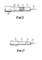
- Fig.1 is a view in side elevation, partly in section of a communications cable; and
- Fig.2 is a view in side elevation, partly in section of a power cable.
- Referring to Fig.1 a communications cable comprises an
inner conductor 10 for example of copper surrounded by dielectric 12 which may be cellular and made for example of plastics such as polyethylene. The dielectric is covered by a metal-braid 14 which may be of copper. The braid is covered by a laminate according to the invention consisting of afirst layer 16 of plastics material such as polypropylene bonded to a second outer andharder layer 18 of plastics material such as polypropylene by abonding layer 20 which is a mixture of the materials oflayers - In a specific example of the embodiment of Fig.1 just described
layer 16 is of low density polyethylene and is applied.over a screen diameter of 10.76 mm to a diameter of 13.0 mm. Thebonding layer 20 is a 50/50 by volume mixture of low density polyethylene/polypropylene and is applied onlayer 16 to a diameter of 13.4 mm. Finally theouter layer 18 of polypropylene is applied on the bonding layer to a diameter of 14.45 mm. - The cable so produced was compared with a prior art cable which did not have the laminate outer sheath of the present invention but a substantially homogenous outer sheath of polyethylene. The overall diameter of the prior art cable was 13 mm. The maximum length of prior art cable that could be pulled through ducting or conduit was found to be about 70 metres. Such a length required at least two men pulling the cable and one pushing.
- The cable of the invention, which was of slightly larger size than the prior art cable could be pulled with ease by one man through the same size ducting in lengths in excess of 240 m. The outer surface of the cable of the invention had a very much lower coefficient of friction than the prior art cable. In addition the laminate outer sheath gave the cable improved tensile and compression strength compared to the prior art cable.
- The second example concerns polyvinyl chloride insulated cables used in power wiring systems, such as in the home. The cable is susceptible to damage during installation as it is pulled in through conduit or apertures in junction boxes or other fittings, where the edges of the aperture can strip the insulating material off the cable. If a very hard grade of polyvinyl chloride having low frictional resistance properties is selected as the outer layer of the cable and bonded to a softer inner layer of PVC, the possibility of damage is greatly reduced and ease of installation is greatly improved. Often more individual cables may be pulled into a single conduit than at present.
- Referring to Fig.1 a single core power cable comprises a
conductor 30 for example of copper. The conductor is sheathed by the laminate of the invention comprising afirst layer 32 of plastics such as soft grade polyvinyl chloride, abonding layer 34 and anouter layer 36 of plastics such as hard grade polyvinyl chloride. The bonding layer consisted of a 50/50 by volume mixture of hard and soft grade polyvinyl chloride. - In a specific example of the above embodiment the conductor diameter is 1.78 mm and is insulated by the laminate of the invention to a diameter of 3.5 mm. The ratio of diameters between the three layers is 2:0.4:1.
- The cable so produced is considerably stronger both in tension and compression than prior art cables. In addition it had a surface of relatively low coefficient of friction so that it was easier to pull through conduit than prior art cables.
- The examples clearly show the advantages that the use of the invention gives in connection with cables.
- Because longer lengths can be pulled through conduit fewer joints are required to connect the lengths together. The savings that result are very great because in cable installations it is the cost of the joints that is one of the major expenses. The ease with which the cable can be pulled through ducting means that severe tensile forces are not applied to the cable, but in any event the cable of the invention can withstand increased tensile stress, because of the increased tensile strength imparted to the cable by the laminate. The increase in both tensile and compression strength given by the invention is of the order of 50%
- The invention is not confined only to use with cables as described in the examples. It can be used in a variety of different applications. For example it can be used as a sheath for optical fibres where-the high strength of the laminate gives very good protection to the fibres. The expense of joining optical fibres is even greater than joining power cables or communication cables so that the advantages of being able to pull long lengths through ducting are even greater. In addition the high tensile strength protects the fibres when they are pulled through ducting and moreover less tensile forces are applied because of the low coefficient of friction of the laminate surface.
- The laminate may also be used as a lining for ducting. Such application gives a further reduction in the friction developed when cables are pulled through the ducting.
- Another application for the laminate of the invention is in connection with containers where there are requirements for the interior to be of a different material to the exterior.
Claims (15)
Priority Applications (1)
| Application Number | Priority Date | Filing Date | Title |
|---|---|---|---|
| AT81304635T ATE17208T1 (en) | 1980-10-10 | 1981-10-06 | CABLE WITH A CONDUCTOR SHEATH. |
Applications Claiming Priority (2)
| Application Number | Priority Date | Filing Date | Title |
|---|---|---|---|
| GB8032787 | 1980-10-10 | ||
| GB8032787 | 1980-10-10 |
Publications (3)
| Publication Number | Publication Date |
|---|---|
| EP0051922A2 true EP0051922A2 (en) | 1982-05-19 |
| EP0051922A3 EP0051922A3 (en) | 1983-01-05 |
| EP0051922B1 EP0051922B1 (en) | 1986-01-02 |
Family
ID=10516592
Family Applications (1)
| Application Number | Title | Priority Date | Filing Date |
|---|---|---|---|
| EP81304635A Expired EP0051922B1 (en) | 1980-10-10 | 1981-10-06 | Cable having a sheath surrounding a conductor |
Country Status (17)
| Country | Link |
|---|---|
| US (1) | US4514036A (en) |
| EP (1) | EP0051922B1 (en) |
| JP (1) | JPS5795010A (en) |
| AT (1) | ATE17208T1 (en) |
| AU (1) | AU544264B2 (en) |
| BR (1) | BR8106592A (en) |
| CA (1) | CA1194565A (en) |
| DE (1) | DE3173390D1 (en) |
| DK (1) | DK158998C (en) |
| ES (1) | ES506154A0 (en) |
| FI (1) | FI72462C (en) |
| HK (1) | HK37988A (en) |
| IE (1) | IE51681B1 (en) |
| IL (1) | IL64056A (en) |
| IN (1) | IN157065B (en) |
| NO (1) | NO154299C (en) |
| ZA (1) | ZA817011B (en) |
Cited By (3)
| Publication number | Priority date | Publication date | Assignee | Title |
|---|---|---|---|---|
| US4684214A (en) * | 1984-01-04 | 1987-08-04 | Siemens Aktiengesellschaft | Cable with a friction reducing outside layer |
| EP0284714A2 (en) * | 1987-03-28 | 1988-10-05 | Ewald Dörken GmbH & Co. KG | Laminated sheet |
| EP0435787A2 (en) * | 1989-12-28 | 1991-07-03 | American National Can Company | Blended films, structures therefrom, and methods of making and using them |
Families Citing this family (15)
| Publication number | Priority date | Publication date | Assignee | Title |
|---|---|---|---|---|
| JPS6069606A (en) * | 1983-09-27 | 1985-04-20 | Toomen:Kk | Filxible optical fiber bundle |
| US5230033A (en) * | 1984-11-01 | 1993-07-20 | Optelecom, Inc. | Subminiature fiber optic submarine cable and method of making |
| US4886562A (en) * | 1987-03-31 | 1989-12-12 | The Boeing Company | Method of manufacturing reinforced optical fiber |
| US5024506A (en) * | 1989-01-27 | 1991-06-18 | At&T Bell Laboratories | Plenum cables which include non-halogenated plastic materials |
| US4969706A (en) * | 1989-04-25 | 1990-11-13 | At&T Bell Laboratories | Plenum cable which includes halogenated and non-halogenated plastic materials |
| US4946237A (en) * | 1989-06-30 | 1990-08-07 | At&T Bell Laboratories | Cable having non-metallic armoring layer |
| US5083875A (en) * | 1990-10-15 | 1992-01-28 | W. L. Gore & Associates, Inc. | Terminated high-strength fiber optic cables and method for termination thereof |
| US5719353A (en) * | 1995-06-13 | 1998-02-17 | Commscope, Inc. | Multi-jacketed coaxial cable and method of making same |
| US6028975A (en) * | 1998-01-13 | 2000-02-22 | Sun Microsystems, Inc. | Low thermal skew fiber optic cable |
| DE10236288A1 (en) * | 2002-08-08 | 2004-02-26 | Nexans | Electric cable |
| US7702203B1 (en) | 2008-10-30 | 2010-04-20 | Corning Cable Systems Llc | Armored fiber optic assemblies and methods of making the same |
| US8463095B2 (en) | 2009-04-09 | 2013-06-11 | Corning Cable Systems Llc | Armored fiber optic assemblies and methods of forming fiber optic assemblies |
| US8331748B2 (en) * | 2009-09-30 | 2012-12-11 | Corning Cable Systems Llc | Armored fiber optic assemblies and methods employing bend-resistant multimode fiber |
| US9170390B2 (en) | 2010-04-23 | 2015-10-27 | Corning Cable Systems Llc | Armored fiber optic assemblies and methods of forming fiber optic assemblies |
| US10297365B2 (en) * | 2016-10-31 | 2019-05-21 | Schlumberger Technology Corporation | Cables with polymeric jacket layers |
Citations (6)
| Publication number | Priority date | Publication date | Assignee | Title |
|---|---|---|---|---|
| DE1153512B (en) * | 1961-02-28 | 1963-08-29 | Calor Emag Elektrizitaets Ag | Process for the production of molded parts which have a layer of hardenable and a layer of non-hardenable or elastic plastic |
| US3422215A (en) * | 1967-02-16 | 1969-01-14 | Westinghouse Electric Corp | Insulated cable |
| US3616177A (en) * | 1969-09-17 | 1971-10-26 | Du Pont | Laminar structures of polyimides and wire insulated therewith |
| US4123576A (en) * | 1975-07-23 | 1978-10-31 | Kureha Kagaku Kogyo Kabushiki Kaisha | Bonding a multi-layered structure of olefin-containing and nitrile-containing polymers and article |
| EP0010246A1 (en) * | 1978-10-12 | 1980-04-30 | BASF Aktiengesellschaft | Laminates from filled polyolefins and a thermoplastic decorative layer; method of making same and application |
| EP0016614A1 (en) * | 1979-03-15 | 1980-10-01 | The Standard Oil Company | Laminated structure comprising a nitrile resin barrier layer, a tie layer and a polyolefin layer, and coextrusion process for making said structure |
Family Cites Families (10)
| Publication number | Priority date | Publication date | Assignee | Title |
|---|---|---|---|---|
| US2707205A (en) * | 1953-05-15 | 1955-04-26 | Us Rubber Co | Insulated electrical conductor and method of making same |
| US3482033A (en) * | 1966-08-04 | 1969-12-02 | Simplex Wire & Cable Co | Manufacture of high voltage polyolefin insulated cable and article |
| US3687748A (en) * | 1970-04-09 | 1972-08-29 | Dow Chemical Co | Method of fabricating cables |
| US3798115A (en) * | 1972-02-01 | 1974-03-19 | Basf Ag | Laminates of polypropylene and polyamide |
| US3852518A (en) * | 1973-11-29 | 1974-12-03 | Gen Cable Corp | Irradiation cross-linked composite low density/high density polyethylene insulated 600 volt power cables |
| JPS54688B2 (en) * | 1973-12-26 | 1979-01-13 | ||
| JPS5148499A (en) * | 1974-10-18 | 1976-04-26 | Tomoji Suzuki | SEICHASENBETSUSOJUHOHO OYOBI SONOSOCHI |
| CA1067388A (en) * | 1975-10-22 | 1979-12-04 | Ernest J. Buckler | Filled-polystyrene laminates |
| US4024316A (en) * | 1976-01-22 | 1977-05-17 | Joe Loris | Insulated safetysized equipment |
| US4292463A (en) * | 1977-12-14 | 1981-09-29 | The Dow Chemical Company | Cable shielding tape and cable |
-
1981
- 1981-10-06 DE DE8181304635T patent/DE3173390D1/en not_active Expired
- 1981-10-06 IN IN643/DEL/81A patent/IN157065B/en unknown
- 1981-10-06 EP EP81304635A patent/EP0051922B1/en not_active Expired
- 1981-10-06 AT AT81304635T patent/ATE17208T1/en not_active IP Right Cessation
- 1981-10-07 DK DK444181A patent/DK158998C/en not_active IP Right Cessation
- 1981-10-08 CA CA000387575A patent/CA1194565A/en not_active Expired
- 1981-10-08 FI FI813129A patent/FI72462C/en not_active IP Right Cessation
- 1981-10-09 ZA ZA817011A patent/ZA817011B/en unknown
- 1981-10-09 IE IE2366/81A patent/IE51681B1/en not_active IP Right Cessation
- 1981-10-09 NO NO813413A patent/NO154299C/en unknown
- 1981-10-09 ES ES506154A patent/ES506154A0/en active Granted
- 1981-10-12 JP JP56163352A patent/JPS5795010A/en active Pending
- 1981-10-12 AU AU76253/81A patent/AU544264B2/en not_active Ceased
- 1981-10-13 BR BR8106592A patent/BR8106592A/en unknown
- 1981-10-15 IL IL64056A patent/IL64056A/en unknown
-
1983
- 1983-08-01 US US06/518,328 patent/US4514036A/en not_active Expired - Lifetime
-
1988
- 1988-05-19 HK HK379/88A patent/HK37988A/en not_active IP Right Cessation
Patent Citations (6)
| Publication number | Priority date | Publication date | Assignee | Title |
|---|---|---|---|---|
| DE1153512B (en) * | 1961-02-28 | 1963-08-29 | Calor Emag Elektrizitaets Ag | Process for the production of molded parts which have a layer of hardenable and a layer of non-hardenable or elastic plastic |
| US3422215A (en) * | 1967-02-16 | 1969-01-14 | Westinghouse Electric Corp | Insulated cable |
| US3616177A (en) * | 1969-09-17 | 1971-10-26 | Du Pont | Laminar structures of polyimides and wire insulated therewith |
| US4123576A (en) * | 1975-07-23 | 1978-10-31 | Kureha Kagaku Kogyo Kabushiki Kaisha | Bonding a multi-layered structure of olefin-containing and nitrile-containing polymers and article |
| EP0010246A1 (en) * | 1978-10-12 | 1980-04-30 | BASF Aktiengesellschaft | Laminates from filled polyolefins and a thermoplastic decorative layer; method of making same and application |
| EP0016614A1 (en) * | 1979-03-15 | 1980-10-01 | The Standard Oil Company | Laminated structure comprising a nitrile resin barrier layer, a tie layer and a polyolefin layer, and coextrusion process for making said structure |
Cited By (5)
| Publication number | Priority date | Publication date | Assignee | Title |
|---|---|---|---|---|
| US4684214A (en) * | 1984-01-04 | 1987-08-04 | Siemens Aktiengesellschaft | Cable with a friction reducing outside layer |
| EP0284714A2 (en) * | 1987-03-28 | 1988-10-05 | Ewald Dörken GmbH & Co. KG | Laminated sheet |
| EP0284714A3 (en) * | 1987-03-28 | 1989-12-06 | Ewald Dörken GmbH & Co. KG | Laminated sheet |
| EP0435787A2 (en) * | 1989-12-28 | 1991-07-03 | American National Can Company | Blended films, structures therefrom, and methods of making and using them |
| EP0435787A3 (en) * | 1989-12-28 | 1992-06-24 | American National Can Company | Blended films, structures therefrom, and methods of making and using them |
Also Published As
| Publication number | Publication date |
|---|---|
| FI72462C (en) | 1987-06-08 |
| CA1194565A (en) | 1985-10-01 |
| IL64056A (en) | 1985-06-30 |
| ES8304699A1 (en) | 1983-03-01 |
| ZA817011B (en) | 1982-09-29 |
| NO154299C (en) | 1986-08-27 |
| DK444181A (en) | 1982-04-11 |
| HK37988A (en) | 1988-05-27 |
| NO813413L (en) | 1982-04-13 |
| IL64056A0 (en) | 1982-01-31 |
| AU544264B2 (en) | 1985-05-23 |
| DE3173390D1 (en) | 1986-02-13 |
| JPS5795010A (en) | 1982-06-12 |
| IN157065B (en) | 1986-01-04 |
| NO154299B (en) | 1986-05-20 |
| EP0051922A3 (en) | 1983-01-05 |
| DK158998C (en) | 1991-04-08 |
| IE812366L (en) | 1982-04-10 |
| EP0051922B1 (en) | 1986-01-02 |
| DK158998B (en) | 1990-08-13 |
| FI813129L (en) | 1982-04-11 |
| AU7625381A (en) | 1982-04-22 |
| BR8106592A (en) | 1982-06-29 |
| ATE17208T1 (en) | 1986-01-15 |
| US4514036A (en) | 1985-04-30 |
| FI72462B (en) | 1987-02-27 |
| ES506154A0 (en) | 1983-03-01 |
| IE51681B1 (en) | 1987-02-04 |
Similar Documents
| Publication | Publication Date | Title |
|---|---|---|
| US4514036A (en) | Cable having a laminated plastic insulating sheath | |
| EP0175419B1 (en) | Signal transmission cable | |
| US4125739A (en) | Cable shielding tape and cable | |
| US7351009B2 (en) | Fiber optic installation structures in a paved surface, ducts, and methods therefor | |
| US6215070B1 (en) | Electric power cables | |
| US3800065A (en) | Grounded power cable | |
| US3891791A (en) | Communication cable with improved coated shield | |
| GB2084927A (en) | Lamination of plastics | |
| AU743771B2 (en) | Electric power cables | |
| CA1073538A (en) | Power cables of concentric neutral construction | |
| CN85103383A (en) | Signal-transmitting cable |
Legal Events
| Date | Code | Title | Description |
|---|---|---|---|
| PUAI | Public reference made under article 153(3) epc to a published international application that has entered the european phase |
Free format text: ORIGINAL CODE: 0009012 |
|
| AK | Designated contracting states |
Designated state(s): AT BE CH DE FR GB IT LI LU NL SE |
|
| PUAL | Search report despatched |
Free format text: ORIGINAL CODE: 0009013 |
|
| AK | Designated contracting states |
Designated state(s): AT BE CH DE FR GB IT LI LU NL SE |
|
| 17P | Request for examination filed |
Effective date: 19821116 |
|
| RBV | Designated contracting states (corrected) |
Designated state(s): AT BE CH DE FR IT LI LU NL SE |
|
| RAP1 | Party data changed (applicant data changed or rights of an application transferred) |
Owner name: RAYDEX INTERNATIONAL LIMITED |
|
| GRAA | (expected) grant |
Free format text: ORIGINAL CODE: 0009210 |
|
| AK | Designated contracting states |
Designated state(s): AT BE CH DE FR IT LI LU NL SE |
|
| REF | Corresponds to: |
Ref document number: 17208 Country of ref document: AT Date of ref document: 19860115 Kind code of ref document: T |
|
| REF | Corresponds to: |
Ref document number: 3173390 Country of ref document: DE Date of ref document: 19860213 |
|
| ITF | It: translation for a ep patent filed |
Owner name: BARZANO' E ZANARDO ROMA S.P.A. |
|
| ET | Fr: translation filed | ||
| PG25 | Lapsed in a contracting state [announced via postgrant information from national office to epo] |
Ref country code: LU Free format text: LAPSE BECAUSE OF NON-PAYMENT OF DUE FEES Effective date: 19861031 |
|
| PLBE | No opposition filed within time limit |
Free format text: ORIGINAL CODE: 0009261 |
|
| STAA | Information on the status of an ep patent application or granted ep patent |
Free format text: STATUS: NO OPPOSITION FILED WITHIN TIME LIMIT |
|
| RAP2 | Party data changed (patent owner data changed or rights of a patent transferred) |
Owner name: VOLEX GROUP PLC |
|
| 26N | No opposition filed | ||
| BECH | Be: change of holder |
Free format text: 860102 *VOLEX GROUP P.L.C. |
|
| NLT2 | Nl: modifications (of names), taken from the european patent patent bulletin |
Owner name: VOLEX GROUP PLC TE SALFORD, GROOT-BRITTANNIE. |
|
| ITPR | It: changes in ownership of a european patent |
Owner name: CESSIONE;VOLEX GROUP PLC |
|
| REG | Reference to a national code |
Ref country code: CH Ref legal event code: PUE Owner name: VOLEX GROUP P.L.C. |
|
| NLS | Nl: assignments of ep-patents |
Owner name: VOLEX GROUP P.L.C. TE SALFORD, GROOT-BRITTANNIE. |
|
| REG | Reference to a national code |
Ref country code: FR Ref legal event code: TP |
|
| PGFP | Annual fee paid to national office [announced via postgrant information from national office to epo] |
Ref country code: SE Payment date: 19901214 Year of fee payment: 10 Ref country code: AT Payment date: 19901214 Year of fee payment: 10 |
|
| PGFP | Annual fee paid to national office [announced via postgrant information from national office to epo] |
Ref country code: CH Payment date: 19901219 Year of fee payment: 10 |
|
| PGFP | Annual fee paid to national office [announced via postgrant information from national office to epo] |
Ref country code: LU Payment date: 19901228 Year of fee payment: 10 |
|
| EPTA | Lu: last paid annual fee | ||
| PG25 | Lapsed in a contracting state [announced via postgrant information from national office to epo] |
Ref country code: AT Effective date: 19911006 |
|
| PG25 | Lapsed in a contracting state [announced via postgrant information from national office to epo] |
Ref country code: SE Effective date: 19911007 |
|
| PG25 | Lapsed in a contracting state [announced via postgrant information from national office to epo] |
Ref country code: LI Effective date: 19911031 Ref country code: CH Effective date: 19911031 |
|
| PGFP | Annual fee paid to national office [announced via postgrant information from national office to epo] |
Ref country code: BE Payment date: 19911113 Year of fee payment: 11 |
|
| REG | Reference to a national code |
Ref country code: CH Ref legal event code: PL |
|
| PG25 | Lapsed in a contracting state [announced via postgrant information from national office to epo] |
Ref country code: BE Effective date: 19921031 |
|
| BERE | Be: lapsed |
Owner name: VOLEX GROUP P.L.C. Effective date: 19921031 |
|
| ITTA | It: last paid annual fee | ||
| EUG | Se: european patent has lapsed |
Ref document number: 81304635.6 Effective date: 19920510 |
|
| REG | Reference to a national code |
Ref country code: FR Ref legal event code: TP Ref country code: FR Ref legal event code: CA |
|
| PGFP | Annual fee paid to national office [announced via postgrant information from national office to epo] |
Ref country code: FR Payment date: 19980925 Year of fee payment: 18 |
|
| PGFP | Annual fee paid to national office [announced via postgrant information from national office to epo] |
Ref country code: DE Payment date: 19981012 Year of fee payment: 18 |
|
| PGFP | Annual fee paid to national office [announced via postgrant information from national office to epo] |
Ref country code: NL Payment date: 19981031 Year of fee payment: 18 |
|
| REG | Reference to a national code |
Ref country code: FR Ref legal event code: CD |
|
| PG25 | Lapsed in a contracting state [announced via postgrant information from national office to epo] |
Ref country code: NL Free format text: LAPSE BECAUSE OF NON-PAYMENT OF DUE FEES Effective date: 20000501 |
|
| PG25 | Lapsed in a contracting state [announced via postgrant information from national office to epo] |
Ref country code: FR Free format text: LAPSE BECAUSE OF NON-PAYMENT OF DUE FEES Effective date: 20000630 |
|
| NLV4 | Nl: lapsed or anulled due to non-payment of the annual fee |
Effective date: 20000501 |
|
| PG25 | Lapsed in a contracting state [announced via postgrant information from national office to epo] |
Ref country code: DE Free format text: LAPSE BECAUSE OF NON-PAYMENT OF DUE FEES Effective date: 20000801 |
|
| REG | Reference to a national code |
Ref country code: FR Ref legal event code: ST |