EP0048265B1 - Method of operating a web processing apparatus and web processing apparatus - Google Patents
Method of operating a web processing apparatus and web processing apparatus Download PDFInfo
- Publication number
- EP0048265B1 EP0048265B1 EP81900917A EP81900917A EP0048265B1 EP 0048265 B1 EP0048265 B1 EP 0048265B1 EP 81900917 A EP81900917 A EP 81900917A EP 81900917 A EP81900917 A EP 81900917A EP 0048265 B1 EP0048265 B1 EP 0048265B1
- Authority
- EP
- European Patent Office
- Prior art keywords
- data
- job
- memory
- web
- press
- Prior art date
- Legal status (The legal status is an assumption and is not a legal conclusion. Google has not performed a legal analysis and makes no representation as to the accuracy of the status listed.)
- Expired
Links
Images


Classifications
-
- G—PHYSICS
- G06—COMPUTING; CALCULATING OR COUNTING
- G06Q—INFORMATION AND COMMUNICATION TECHNOLOGY [ICT] SPECIALLY ADAPTED FOR ADMINISTRATIVE, COMMERCIAL, FINANCIAL, MANAGERIAL OR SUPERVISORY PURPOSES; SYSTEMS OR METHODS SPECIALLY ADAPTED FOR ADMINISTRATIVE, COMMERCIAL, FINANCIAL, MANAGERIAL OR SUPERVISORY PURPOSES, NOT OTHERWISE PROVIDED FOR
- G06Q10/00—Administration; Management
- G06Q10/06—Resources, workflows, human or project management; Enterprise or organisation planning; Enterprise or organisation modelling
-
- G—PHYSICS
- G07—CHECKING-DEVICES
- G07C—TIME OR ATTENDANCE REGISTERS; REGISTERING OR INDICATING THE WORKING OF MACHINES; GENERATING RANDOM NUMBERS; VOTING OR LOTTERY APPARATUS; ARRANGEMENTS, SYSTEMS OR APPARATUS FOR CHECKING NOT PROVIDED FOR ELSEWHERE
- G07C3/00—Registering or indicating the condition or the working of machines or other apparatus, other than vehicles
-
- Y—GENERAL TAGGING OF NEW TECHNOLOGICAL DEVELOPMENTS; GENERAL TAGGING OF CROSS-SECTIONAL TECHNOLOGIES SPANNING OVER SEVERAL SECTIONS OF THE IPC; TECHNICAL SUBJECTS COVERED BY FORMER USPC CROSS-REFERENCE ART COLLECTIONS [XRACs] AND DIGESTS
- Y02—TECHNOLOGIES OR APPLICATIONS FOR MITIGATION OR ADAPTATION AGAINST CLIMATE CHANGE
- Y02P—CLIMATE CHANGE MITIGATION TECHNOLOGIES IN THE PRODUCTION OR PROCESSING OF GOODS
- Y02P90/00—Enabling technologies with a potential contribution to greenhouse gas [GHG] emissions mitigation
- Y02P90/80—Management or planning
Definitions
- This invention relates to a method of operating a web processing apparatus and a web processing apparatus, in particular large web printing presses capable of printing upon one or more webs in a number of different colors, and of separating and folding the printed web into sheets or signatures.
- Such equipment is well known, and automatic controls for such equipment have been utilized for many years, primarily for the purpose of starting, stopping, jogging, and otherwise controlling the various functions of the press and its sections, and related equipment, and to monitor various conditions and provide warnings or emergency controls as desired.
- Such automated control equipment has developed over the years, from hard wired control circuits, usually involving various relays, switches, etc., into more sophisticated computer controlled systems which perform the same function, or expanded such functions, using solid state components and micro or mini computer equipment.
- this equipment is to control the press, to stop it or give warnings, as may be necessary, in the event of failures or potential failures, and otherwise to assist the press operating crew in the actual makeready and operation of the press, in a semi-automated manner.
- GB-A-2024457 describes a makeready and control system for a printing press comprising a web supply for mounting at least one roll of web material and for withdrawing the material from the roll, a plurality of printing units through which the web is guided and at which different operations are performed on the web, a drive providing motive power to the printing units, and delivery means receiving the web material from the printing units.
- the control system effects presetting of various mechanical elements of the press, and otherwise controlling the makeready, in accordance with a plurality of factors, including product dependent factors and press dependent factors, to properly print the product.
- control system includes means for inputting data stored in a memory at the control station or entered via a manual data entry device (keyboard) thereat, which is indicative of the jobs and of these plurality of factors, and a number of dedicated electronic processors each associated with one type of mechanical setting (i.e. ink fountains, water fountains, registration elements, etc.) process this data in order to derive control information therefrom and cause an associated control circuit to preset the corresponding mechanical setting, the mechanical setting actuating detectors providing feed back information to the processor so that the operator can view the settings on data output devices (video displays) seen by the operator.
- a manual data entry device keyboard
- dedicated electronic processors each associated with one type of mechanical setting (i.e. ink fountains, water fountains, registration elements, etc.) process this data in order to derive control information therefrom and cause an associated control circuit to preset the corresponding mechanical setting
- the mechanical setting actuating detectors providing feed back information to the processor so that the operator can view the settings on data output devices (video displays) seen by the operator.
- Each video display may be edited and revised to change the setting by the operator using the associated manual data entry device (keyboard), both the original and edited data being stored in a memory for later retrieval.
- a printer communicates with the processors to provide print outs of some of the processed data.
- This prior control system only uses the stored or edited data to indicate the manners in which the web and printing plates must be applied and other press configuration details and also to preset the adjustment of ink fountains, water fountains and other adjustable elements of the press, all as required during makeready for a particular job, and is in no way concerned with nor capable of centrally monitoring the entire operation and progress of the machine from makeready through completion of a job run.
- US-A-4089056 discloses a system for the automatic supervision of a multiplicity of machines in a manufacturing plant, including a set of transducer units individual to the respective machines for converting their operating speeds into binary data which are successively read out, under the control of a scanner sequentially activating respective couplers, to a tape puncher together with data identifying the machines and their operators.
- the punched tape is then fed to a computer which interprets the received data and passes out the results on another tape scanned by a reader for purposes of visual display and transmission to a display panel.
- the transmission of the results from the reader to the display panel takes place at certain periods under the control of a timer-operated gating circuit.
- the object of the present invention is to provide a method of operating a web processing apparatus and a web processing apparatus, such as a printing press, of which the equipment is an adjunct to the machine controls and detects events, combinations of events and sequences of events arising during the makeready and run modes of the machine, whereby to centrally monitor and analyse the entire operations and progress of the machine and its various processing units, and also of the crew operating the machine, in order to achieve the most efficient operation, to predict or estimate performance standards, to provide guidance (or performance feed back) to the crew, and to provide various records which can be analyzed to assist in achieving a satisfactory regular maintenance program for the machine.
- a press management and analysis system for a web printing press embodying a press monitoring and analysis console (PMA) which is located adjacent the press to which it is related, together with a remote entry computer (REC) with which the PMA can communicate, together with various sensor devices on the press, the states of which are monitored by the PMA and decoded in order to follow the operation of the press from the beginning of a job assignment, through makeready operations, and through the printing operation to completion of the job.
- PMA press monitoring and analysis console
- REC remote entry computer
- PMA console typically there is one PMA console for each press in the shop, and a single REC console remote from the press room, as in the production manager's office.
- the REC can communicate with each PMA, and recording (filing), hard copy printing, and like functions are handled at the REC console.
- the system provides a number of displays which require completion by the pressman/operator, thus soliciting information from him (or in some cases from the manager's office) as well as informing all concerned of job progress, of standard times expected for a given job, and of transfer from one state or phase of the job, as from makeready time to run time in which good product is printed.
- the system monitors press functions to feed back and record event messages, and it encourages operator input and identification of stoppage reasons, etc., thereby building a job file for the press which is useful for many management purposes.
- the system retains certain coefficients which are used at the beginning of a job, along with input job data, to calculate the standard times for a job of given magnitude, and then incorporates the results of such calculations in the displays for makeready time and run time as standards against which actual times are compared. Alarms are created when projected or actual time exceeds calculated standard time.
- the filed information is available for management analysis of the press operation, as in the form of reports compiling desired data into a printer produced report copy at the REC. Such information may, optionally, also be communicated to a host computer for storage and/or further analysis.
- the reports not only identify press and/or crew efficiency or problems, but also provide valuable guidance for maintenance and other management decisions.
- the primary object of the invention is to provide a management and/or analysis system for use with a printing press, particularly a web press, or similar machine in which multiple functions are performed in registration; to provide such a system which assists and encourages an operator to enter into the system information which is useful for management, operational analysis, time keeping and/or maintenance purposes; to provide such a system which has capability to display to the operator, as on a video terminal, various formats to be completed by the operator through a data entry device; to provide such a system which monitors the progress of a press through a job and displays to the operator an appropriate graphic representation of such progress; to provide such a system which also displays graphic representation of time standards for the progress of a job having certain known requirements; to provide such a system which will generate an alert when actual progress on a job phase exceeds a standard therefor; and to provide such a system which can generate hard copy reports for management and maintenance purposes.
- a typical web printing press shows a supply for web material indicated generally at 10.
- this may include supports for multiple rolls of paper or other web material, whereby one or more webs may be supplied and threaded through the press simultaneously.
- a typical commercial multicolor offset printing press may print simultaneously on both sides of two different webs, which may even be of dissimilar grades of paper.
- this supply may be in the form of a well known mechanism known in the art as a reel stand which includes provision to support at least four rolls of web material W1, W2, W3, W4, and these feeding into two different accumulator devices (not shown).
- each printing unit includes the usual upper and lower printing couples for printing on opposite sides of the web material threaded therethrough, and these include upper and lower blanket cylinders, plate cylinders, inkers, dampeners, etc. which are per se well known.
- a typical multicolor operation prints the color black first, for example on printing unit 11 or 12, and then subsequently prints in other colors registering these other colors to the base or black print.
- the printed web materials enter a dryer unit 20 which includes conventional upper and lower heated drying equipment for the multiple webs. Following the drying unit are upper and lower chill rolls 22 which receive and cool the web material leaving the dryer, and following the chill rolls there may be further web guiding and coating equipment, as for applying a silicone coating to one or both sides of the web material, these being indicated generally at 24. Finally the web material passes into the folding equipment 25 where the web material may be folded lengthwise, folded across its width and separated into individual signatures, and from the folders the material may pass to conventional stackers or other suitable delivery equipment.
- a drive including an electric motor 27 and line shaft 28 provides a power source for at least all the printing units and the infeed mechanism.
- the dryer, chill rolls, folders, and delivery equipment may have separate power sources.
- Phase I of makeready time may involve preparation of the various parts of the press, at a standstill, such as mounting new blankets, hanging the necessary plates for the job, washing-up the various rolls, etc. in preparation for a new job, mounting the rolls of web material, and threading this web material through the various printing units and subsequent dryers, coaters, folders, etc. in accordance with the requirements of that particular job.
- phase II makeready MR2
- the operator or crew chief indicates in some manner that the "good count” has begun, and from that point on the product is saved and stacked, etc. as necessary to fulfill the job requirements.
- the various printing units and other equipment may need to be declutched from the drive and line shaft, may need to be manipulated and rotated by hand, or may need to be jogged through the drive, as called for during various steps of the makeready process.
- Such process again, is well known, and the various steps required will depend upon the exact type of printing equipment, the nature of the product, and other factors which need not be considered here.
- the purpose of the present invention is to assist the crew in the entire operation of the equipment, from the beginning of makeready throughout the job, by accepting information input by the crew, or by the manager of the printing establishment, by constantly monitoring the progress of each job, recording pertinent information in the form of event messages, assisting the crew by exhibiting various displays which encourage feed back into the system of exact information as to what is occurring during a job, what deviations may be encountered from the normal expected steps of the job, identifying such deviations or stoppages, including the reasons for them, and in general providing a data base from which the continuing - usage of the press can be more effectively managed.
- bar graphs which will show a standard time for a given job, the actual time being required to reach certain steps in the progress of the job, projected total based on actual progress, and other related data including alarms when the job is running beyond projected time requirements, or has encountered some emergency which requires that the press be shut down unexpectedly.
- the press and related equipment is provided with a large number of sensors 29.
- these fall into three different classes.
- One type involves contacts on existing switches or relays, indicating that a particular device is in one of two states
- another type is digital information which may be obtained from counters.
- Typical digital outputs would be for press speed, elapsed total time, gross or total impression count, and good count.
- some sensor devices may be in the form of analog output mechanisms, the outputs of these being compared against a standard for that particular associated function or mechanism, so that abnormal readings from the analog devices will result in outputs.
- the remote entry computer equipment REC console 30 which is housed in a desk 31 and includes a smart color CRT terminal 33, an entry keyboard 34 associated therewith, a microcomputer 35 which may, for example, include an Intel model 8080 microprocessor, a communications module (not illustrated) housed with the computer, a magnetic disc recorder 36 which may be for example a dual floppy disc drive, and a suitable printer 37.
- a microcomputer 35 which may, for example, include an Intel model 8080 microprocessor, a communications module (not illustrated) housed with the computer, a magnetic disc recorder 36 which may be for example a dual floppy disc drive, and a suitable printer 37.
- the REC is intended to be located remote from the press room, for example in the office of the production manager or pressroom foreman of the printing house, where he or a member of his staff may observe the terminal 33, and may input data via the REC keyboard 34. Someone in this location may also be responsible for the handling of hard copy output, such as reports, from the aforementioned printer which is a part of the REC.
- the press management and analysis equipment hereinafter referred to as PMA
- the PMA console incorporates a data output device in the form of a color CRT terminal 42, a bank of LED digital displays 43, 44 and 45 which output from digital counters, and a data input device in the form of a keyboard 47 which is shown in greater detail in Fig. 4.
- the PMA console is located on the printing room floor, preferably adjacent the press shown in Fig. 2, where it is accessible to the press crew, it being intended that the crew chief or some designated crew member be responsible for monitoring the PMA terminal 42 and for entering data via the keyboard 47.
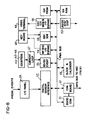
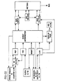
- Fig. 8 of the drawings illustrates in the form of a hardware block diagram the type and arrangement of the PMA processing electronics equipment, which is housed in the PMA console 40.
- Fig. 5 As shown broadly in Fig. 5, and also indicated in Fig. 7 at the bottom, provisions are included in the system for connection of the REC and the PMA via a communications module to a general purpose host computer, which may be used to provide a storage file of job operations information. This feature is merely an adjunct and not a necessary part of the system.
- Figs. 5, 7, 21 and 22 the general cooperation between the press, the PMA and the REC is depicted in terms of various operations.
- Fig. 21 indicates the event codes used by the system to detect transitions from one operation to the next. Event codes derived from signals detected by the sensors 29 on the press are explained hereafter in connection with Table I.
- Operations codes are entered into the system via the PMA keyboard.
- operation codes are required to distinguish between operations that cannot be differentiated by means of event codes.
- a listing of the operation codes appears in Figs. 19 and 20 which show the menu displays that are available to the PMA operator to refresh his memory concerning these various codes.
- the basic functions of the PMA computer module are to (1) detect events that represent transitions from one operation to the next and transmit event messages describing the circumstances of the event to the REC for storage and (2) accumulate time spent in each operation and transmit operation messages containing these times to the REC for storage (filing). Also, operation messages containing the number of net signatures (output product) and of waste associated with each operation, may be detected and transmitted.
- the REC stores or files event and operations messages, generates alerts for certain kinds of event messages, and also stores status information for the PMA during periods when power is off at the PMA.
- the PMA module is housed in the console 40.
- the equipment includes the keyboard 47 (Fig. 4) the color CRT 42 and the counter displays 43-45 which comprise the complete display device, as well as power supply and maintenance equipment all housed in the cabinet.
- the controls for the press include a relay rack which is part of the control system and most connections from the PMA module to the press are provided through contacts in this relay control.
- the PMA keyboard or entry device shown in Fig. 4 is intended to minimize button pushes for major functions, while providing for expansion in case additional features needed to be added to the system. Keyboard operation may be summarized as follows:
- the color CRT 42 provides part of a display device, along with three digital displays 43-45 which are part of counters.
- three digital displays 43-45 which are part of counters.
- one four digit counter display 43 is used for press speed, and two six digit displays.44 and 45 are provided for gross count and good count, respectively and each of these includes a reset button.
- the heart of the system is the PMA computer module, and its basic functions are
- Fig. 8 is a block diagram of the electronic hardware in a typical PMA console.
- it consists of three single board computers 50, 51, 52 (Intel Model SBC 80/20), each of which includes an eight-bit CPU, a system clock 53, a 2K RAM, an 8K PROM, programmable parallel input-output (I/O) lines which are implemented by Intel type 8255 peripheral interface devices, an RS 232C interface device, an Intel type 8253 interval timer, an Intel type 8259 interrupt controller, and bus control logic and driver circuits. These are all per se known devices.
- a memory and input-output expansion board 56 (Intel Model SBC 108) consisting of a RAM, a PROM, an Intel type 3222 refresh controller, two type 8255 programmable peripheral interfaces which provide programmable I/O lines, an interval timer, a multiplexer, an RS 232C interface circuit, and control logic and driver circuits.
- a special input-output expansion board (Intel SBC 508) receives inputs from keyboard 47, and includes four input and four output ports.
- the internal PMA multibus provides communication among
- Fig. 9 is a block diagram of the hardware arrangement of the REC.
- the REC consists primarily of an ISC8001 terminal/computer, an Intel SBC660 chassis which holds the main computer, a dual Shugart disk storage unit, and a Centronics printer.
- the ISC8001 (Intelligent Systems Corporation) is a self-contained microcomputer with- an 8080 microprocessor, 8K bytes of display RAM, up to 24K bytes of user program storage.
- the ISC also has a keyboard input and a serial port for two way communications to the main computer. Eleven different displays are preprogrammed into the ISC, making it an intelligent device. Simple requests are made by the main processor since the burden of display generation is on the ISC. It also pre-processes keyboard input, and only notifies the host when valid operator entries are made. Communication to the main processor is via a standard RS232 terminal interface.
- the Intel SBC660 chassis holds the bulk of the processing capabilities and consists of:
- the disc storage consists of two Shugart 801 floppy disc drives. Each drive is single density and capable of storing 2002 blocks of 128 bytes. Each disc is organized into files, a directory of which is. maintained on the disc.
- the main computer 80/20 maintains files through the SBC201 floppy disc controller.
- the video terminal 33 and keyboard 34 thus provide an information input/output device to supervisory personnel, the disk drive and printer provide memory storage and hard copy for reports, etc., and the main computer 35 controls the management and transfer of information by the REC.
- the components are per se standard items and details of their cooperation in the system will be apparent to persons skilled in the art of data processing and equipment.
- Detected events are tagged with job-form-run number, time, good count, gross count, press speed and point of occurrence, to provide event messages.
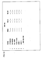
- Table I at the end of the specification, identifies the sensors for a typical installation. These are illustrated schematically in Fig. 2, under the term Press Signal Sensors. The numerals associated with the sensor identification are bit assignments which are useful in understanding the interpretation of messages derived from sensor conditions.
- the PMA computer module interprets bit patterns from these sensors, and distinguishes ten events. These are defined as follows, first by name, then by boolean expression in terms of the bit numbers from Table I, and also in text explanation. The boolean expression is in terms of bit numbers, AND (.), OR (+) and NOT (-).
- the PMA computer module will interpret some button pushes at its keyboard as events independent of the input derived from the press sensors. These other events are defined as
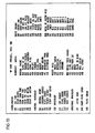
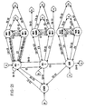
- the network of press operations through a typical job is shown in Fig. 21, with the real time events noted thereon.
- the four basic status symbols are Makeready phase I (MR1), Makeready phase II (MR2), Run, and Other; within the first three, transitions may occur to either "down” or "wait” conditions, depending on the reasons for stoppage or deviation from the usual ongoing makeready and run modes.
- the pentagonal symbols merely indicate event loops, thus any input to symbol A means a return to MR1, any input to symbol B means return to MR2, etc.
- Fig. 22 shows the PMA in basic block diagram form together with the related software tasks.
- the software can take various specific forms, as is known in the programming art, but for purposes of the invention the following software tasks are provided:
- the messages themselves will indicate a unit of measurement in which a quantity is being expressed, but in other instances the unit may not be obvious from the message.
- the following are some typical message fields, and the corresponding units of measurement:
- TIME is accumulated by incrementing a time count each minute that the interval is active. Other values are calculated at interval end according to these equations:
- the PMA hardware provides storage of the following data for an interval:
- intervals E1, E2, E3, E4, and DT are not sent at interval end as is data for the other intervals.
- intervals E1, E2, E3, and E4 may not be continuous, such that the final interval data must be a summation of interval segments data.
- the PMA data base provides eight internal save areas patterned after the interval message:
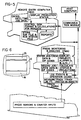
- FIG. 6 shows the regions on the CRT of the PMA console which are utilized for communication with the press crew, usually the crew chief.
- the largest center region, designated D is the region in which the various displays, appear, such as those shown in Fig. 12-20.
- the smaller border region to the top designated AL is used for alarm prompts, and in the preferred embodiment, since a color CRT is used, this region is surrounded by a red rectangle to draw the attention of the operator to the alarm prompt.
- the region at the bottom designated M is used for reminder prompts to the operator, and other instructions during the function of the system, and in the preferred embodiment it is surrounded by a blue border.
- Job standards can then be entered via the REC console by a management or supervisory person.
- the standards are stored in the disc memory and can merely be recalled and displayed at the REC console, or these may be changed if needed. Such standards are used as later explained.
- the REC to PMA Makeready Data message transfers the data to the PMA memory.
- the Crew Data display (Fig. 10) is called up on the CRT of one or the other console, appearing as a table with spaces to be filled in.
- An operator at that console enters the necessary data to identify the crew. For example, crew data will be input at the PMA during each operating shift, an identification number is provided for each member of the crew, and at appropriate times the entry device is also used to provide to the system the times when each particular member of the crew begins and ends his shift.
- a Crew LogOn Message is sent to the REC when the entries are completed at the PMA.
- a further display (Fig. 11) identifies and calls for information needed in association with makeready startup operations. This for example will include identification of the run and job, the number, types, sizes and other characteristics of webs to be used, the number of active printing units, usually related to the number of colors in a job, the number of plates to be used and any information concerning the folder or its operations. Also to be filled in are the number of units involved as concerned with preparation and washup, washing blankets, changing plates, cleaning cylinders, or leading one or more webs through the press.
- the REC display for Production Order is identical to the upper half of the PMA Makeready Startup display. Thus an order can be entered at either.
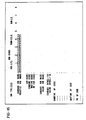
- Fig. 12 shows the Makeready display with only standard and projected makeready bar graphs. This display automatically appears, as soon as Production data is entered, and represents the situation at the beginning of phase I of the makeready period (MR 1). During this time the crew proceeds to hang plates, thread the webs, prepare (but not set) the ink fountains, etc.
- the system is monitoring progress during this period, and for every four minute (one fifteenth of an hour) an Event Message is sent to the REC, and also a graph increment is added where appropriate.
- an Event Message is sent to the REC, and also a graph increment is added where appropriate.
- As the makeready operation "proceeds another bar graph appears on the display, representing accumulated makeready hours.
- This bar which grows in length as the makeready operation proceeds represents actual time elapsed from the beginning of phase I makeready, when this display appeared.
- Also on the display are places for entry for the amount of down time or waiting time for the press, or time required for management functions, and bar graphs showing, individually, accumulated down time, wait time and press management time.
- the display includes provision for a number of down time operating codes which identify specific types of down time during the makeready process, and also a place to enter wait time and press management operating codes.
- the system will charge wait time unless an operator intervenes a particular operating code to identify a specific down time operation to which the elapsed time at this point should be allocated.
- the progress and/or stoppage of normal makeready results in Event messages, including time, operation identifying (OP) code and elapsed time or downtime, being sent regularly to the REC and recorded (filed), and also used to build the display graphs.
- Event messages including time, operation identifying (OP) code and elapsed time or downtime, being sent regularly to the REC and recorded (filed), and also used to build the display graphs.
- OP operation identifying
- phase II of makeready begins. This is recognized as event E5 (see Fig. 21) and the system then automatically updates the makeready display (Fig. 13), with its accumulated graphs. The state is now MR 2, as shown in Fig. 21.
- the system every four minutes calculates makeready projected time and this information is part of the PMA display.
- makeready phase I is begun, the projected time is set equal to the standards, since no operations have occurred. Thereafter, the time associated with washing blankets, leading webs, washing up, and changing plates are all accumulated separately. This is accomplished by using the decoded sensor signals to direct clock information into appropriate time stores or registers, where time for the corresponding operation accumulates.
- PrMT WBT+CPT+LWT+WUT+DT+WT+PM.
- the projected makeready hours bar graph will appear less than the standard makeready hours bar (if the crew is ahead of normal schedule), or equal to standard if the crew is on normal schedule.
- An over standard situation is described below. If the makeready display remains on the PMA display CRT, the projected makeready hour bar will fluctuate vs. the standard according to the situation.
- the system also records a menu of operational (OP) codes and descriptive phrases which the operator can call upon demand should he not have the necessary code memorized at the time it is necessary to enter it at the console for some reason.
- the menu comprises two displays, Figs. 19 and 20, which the operator can recall and readily look up all the various identifications for operational codes necessary to allocate particular operations or occurrences within the term of the makeready and run operations.
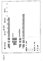
- a typical makeready display is shown in Fig. 13, and includes some downtime and some accumulated waste. It is assumed here that the operator, during phase I makeready, has entered an appropriate OPCODE for the downtime reason (obtained from menu, Figs. 19 or 20, if necessary) and a message has been recorded at the REC. Only the totals are displayed here, not preceding reasons. Waste is represented as one unit (fifteen screen increments) per 4000 impressions.
- Fig. 14 shows the phase II makeready display at a later time. Some more downtime has occurred and the operator has determined it resulted from a web break at the upper infeed. He has entered the OPCODE 540. The bar after this code was deleted once the press again was running and the downtime increased accordingly. The downtime event message has been reported to the REC file. It should also be noted that accumulated waste now equals 4000 impressions, almost one-fourth of the standard for makeready waste.
- Fig. 15 shows the Makeready display later in phase II.
- a further downtime has been encountered which was detected and automatically entered as due to a web break in printing unit one, OPCODE 542; Fig. 21, E8 transition from MR 2 to MR 2 DOWN. After about thirty minutes this was manually terminated by the operator, who determined the actual cause of downtime was due to a mill splice break. He has therefore entered OPCODE 435, and about one hour of downtime has accumulated for that reason.
- the operator, or the production manager if he calls up the Makeready display to the REC, can thus be continuously informed as to the progress of the makeready operation, and if there are any unexpected delays, they will likewise be informed as to the time and nature of these delays.
- the operator will press the GOOD button on the PMA console to indicate that a "good count” has begun. This also indicates that the output of the folders is to be saved from that time on during the run, unless some intervening condition produces waste.
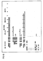
- the PMA display automatically changes to the Run Status display (Fig. 16). It includes bar graphs of standard run hours, standard run waste, and a gradually increasing graph showing actual run hours. Additional graph bars can show down time hours, wait time hours, or management time hours during the term of the run.
- an effective printing rate (speed) is calculated every four minutes.
- presses of this type usually operate from a reel which allows the web from a new roll to be pasted to the end of the web from an exhausted roll (as above described), the system also provides for an accounting of waste resulting from the passage of the paste through the press.
- the good counter having been started by the operator as previously mentioned, is automatically turned off once a predetermined number of gross counts occur after sensing the paste. It is then up to the operator again to signal commencement of a good count as soon as the paste has cleared to the point that and good prints are again available.
- Fig. 17 shows the Run Status display after the run has progressed at a normal (standard) rate for about forty-five minutes.
- the projected run hours are equal to the standard.
- the standard run waste has been displayed, having been calculated from the standards information on file at the REC. Accumulated impression per hour (the Effective Printing Rate) is within standard, and as yet there has not been any run waste.
- Fig. 18 shows the display later on, after a little more than two hours run time.
- a wait is occurring for paper (OPCODE 605), run waste is still below standard, but the accumulated impressions per hour is now just under 24,000/hr, in excess of standard, and the projected run hours now exceeds standard, hence the bar graph for projected run hours has changed color.
- the diagram explains the overall press state sequences with event codes (E0E9) and keyboard derived events (C0-C7), referencing the press modes or states. These are Makeready (MR1 and MR2) and Run.
- the system monitors, prompts, creates and updates displays, and otherwise assists the operating crew, while at the same time providing management information both dynamically and by building operations files which can be used to prepare various hard copy reports. Samples of two such reports are:
Abstract
Description
- This invention relates to a method of operating a web processing apparatus and a web processing apparatus, in particular large web printing presses capable of printing upon one or more webs in a number of different colors, and of separating and folding the printed web into sheets or signatures. Such equipment is well known, and automatic controls for such equipment have been utilized for many years, primarily for the purpose of starting, stopping, jogging, and otherwise controlling the various functions of the press and its sections, and related equipment, and to monitor various conditions and provide warnings or emergency controls as desired. Such automated control equipment has developed over the years, from hard wired control circuits, usually involving various relays, switches, etc., into more sophisticated computer controlled systems which perform the same function, or expanded such functions, using solid state components and micro or mini computer equipment. Still, the basic function of this equipment is to control the press, to stop it or give warnings, as may be necessary, in the event of failures or potential failures, and otherwise to assist the press operating crew in the actual makeready and operation of the press, in a semi-automated manner.
- GB-A-2024457 describes a makeready and control system for a printing press comprising a web supply for mounting at least one roll of web material and for withdrawing the material from the roll, a plurality of printing units through which the web is guided and at which different operations are performed on the web, a drive providing motive power to the printing units, and delivery means receiving the web material from the printing units. The control system effects presetting of various mechanical elements of the press, and otherwise controlling the makeready, in accordance with a plurality of factors, including product dependent factors and press dependent factors, to properly print the product. To this end the control system includes means for inputting data stored in a memory at the control station or entered via a manual data entry device (keyboard) thereat, which is indicative of the jobs and of these plurality of factors, and a number of dedicated electronic processors each associated with one type of mechanical setting (i.e. ink fountains, water fountains, registration elements, etc.) process this data in order to derive control information therefrom and cause an associated control circuit to preset the corresponding mechanical setting, the mechanical setting actuating detectors providing feed back information to the processor so that the operator can view the settings on data output devices (video displays) seen by the operator. Each video display may be edited and revised to change the setting by the operator using the associated manual data entry device (keyboard), both the original and edited data being stored in a memory for later retrieval. A printer communicates with the processors to provide print outs of some of the processed data. This prior control system only uses the stored or edited data to indicate the manners in which the web and printing plates must be applied and other press configuration details and also to preset the adjustment of ink fountains, water fountains and other adjustable elements of the press, all as required during makeready for a particular job, and is in no way concerned with nor capable of centrally monitoring the entire operation and progress of the machine from makeready through completion of a job run.
- US-A-4089056 discloses a system for the automatic supervision of a multiplicity of machines in a manufacturing plant, including a set of transducer units individual to the respective machines for converting their operating speeds into binary data which are successively read out, under the control of a scanner sequentially activating respective couplers, to a tape puncher together with data identifying the machines and their operators. The punched tape is then fed to a computer which interprets the received data and passes out the results on another tape scanned by a reader for purposes of visual display and transmission to a display panel. The transmission of the results from the reader to the display panel takes place at certain periods under the control of a timer-operated gating circuit.
- It is also known from Hilberg & Piloty, "Mikroprozessoren und Ihre Anwendungen", 1977, pages 184-187 and Kussl, "Technick der Prozessdatenverarbeitung", 1973
pages 12, 17, 18, 103-105 to calculate standard times for jobs and to compare these with actual job times. - The object of the present invention is to provide a method of operating a web processing apparatus and a web processing apparatus, such as a printing press, of which the equipment is an adjunct to the machine controls and detects events, combinations of events and sequences of events arising during the makeready and run modes of the machine, whereby to centrally monitor and analyse the entire operations and progress of the machine and its various processing units, and also of the crew operating the machine, in order to achieve the most efficient operation, to predict or estimate performance standards, to provide guidance (or performance feed back) to the crew, and to provide various records which can be analyzed to assist in achieving a satisfactory regular maintenance program for the machine.
- The invention is defined in the appended claims.
- In one embodiment of the invention there is a press management and analysis system for a web printing press embodying a press monitoring and analysis console (PMA) which is located adjacent the press to which it is related, together with a remote entry computer (REC) with which the PMA can communicate, together with various sensor devices on the press, the states of which are monitored by the PMA and decoded in order to follow the operation of the press from the beginning of a job assignment, through makeready operations, and through the printing operation to completion of the job.
- Typically there is one PMA console for each press in the shop, and a single REC console remote from the press room, as in the production manager's office. The REC can communicate with each PMA, and recording (filing), hard copy printing, and like functions are handled at the REC console.
- The system provides a number of displays which require completion by the pressman/operator, thus soliciting information from him (or in some cases from the manager's office) as well as informing all concerned of job progress, of standard times expected for a given job, and of transfer from one state or phase of the job, as from makeready time to run time in which good product is printed. The system monitors press functions to feed back and record event messages, and it encourages operator input and identification of stoppage reasons, etc., thereby building a job file for the press which is useful for many management purposes.
- The system retains certain coefficients which are used at the beginning of a job, along with input job data, to calculate the standard times for a job of given magnitude, and then incorporates the results of such calculations in the displays for makeready time and run time as standards against which actual times are compared. Alarms are created when projected or actual time exceeds calculated standard time.
- The filed information is available for management analysis of the press operation, as in the form of reports compiling desired data into a printer produced report copy at the REC. Such information may, optionally, also be communicated to a host computer for storage and/or further analysis. The reports not only identify press and/or crew efficiency or problems, but also provide valuable guidance for maintenance and other management decisions.
- The primary object of the invention, therefore, is to provide a management and/or analysis system for use with a printing press, particularly a web press, or similar machine in which multiple functions are performed in registration; to provide such a system which assists and encourages an operator to enter into the system information which is useful for management, operational analysis, time keeping and/or maintenance purposes; to provide such a system which has capability to display to the operator, as on a video terminal, various formats to be completed by the operator through a data entry device; to provide such a system which monitors the progress of a press through a job and displays to the operator an appropriate graphic representation of such progress; to provide such a system which also displays graphic representation of time standards for the progress of a job having certain known requirements; to provide such a system which will generate an alert when actual progress on a job phase exceeds a standard therefor; and to provide such a system which can generate hard copy reports for management and maintenance purposes.
-
- Fig. 1 is a perspective view of the REC console;
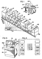
- Fig. 2 is a schematic view of a typical web printing press to which the invention is applicable;
- Fig. 3 is a perspective view of the PMA console;
- Fig. 4 is a diagram on an enlarged scale of the entry keyboard on the PMA console;
- Fig. 5 is a block diagram superimposed upon outlines of the press and the two consoles, showing the overall functional relationship of these;
- Fig. 6 is a drawing of the PMA video display depicting the manner in which messages, alerts, and display formats are presented to an operator;
- Fig. 7 is a diagram presenting an overview of the software system by which the console computers and displays and the press, communicate;
- Fig. 8 is a block diagram of the PMA console electronic hardware;
- Fig. 9 is a block diagram of the REC electronic hardware;
- Figs. 10 through 18 depict various displays which appear at the consoles during operation of the system;
- Figs. 19 and 20 show the operating code information (menu) available to the operator through the PMA;
- Fig. 21 is a system state diagram; and
- Fig. 22 is a basic block diagram of hardware and related software tasks for the PMA.
- Referring first to Fig. 2 of the drawings the diagrammatic representation of a typical web printing press shows a supply for web material indicated generally at 10. In a typical installation this may include supports for multiple rolls of paper or other web material, whereby one or more webs may be supplied and threaded through the press simultaneously. For example, a typical commercial multicolor offset printing press may print simultaneously on both sides of two different webs, which may even be of dissimilar grades of paper. In a typical embodiment this supply may be in the form of a well known mechanism known in the art as a reel stand which includes provision to support at least four rolls of web material W1, W2, W3, W4, and these feeding into two different accumulator devices (not shown). Thus webs from two different rolls can be fed each into an accumulator, and thence into the press as later described, additional rolls of like material can be ready, and when the first webs are depleted the webs from the rolls in reserve can be pasted to the tail of the webs which are depleting while the press momentarily draws web material from the accumulators. Such devices, which are well known, permit the press to continue operation through two or more subsequent rolls of web material, since the reserve rolls can be used while new additional rolls are placed in the position of the fully depleted rolls. At the outlet of the accumulator there is conventionally an infeed mechanism, not shown, which in general controls the payout of the webs into the printing unit of the press, and which may incorporate known types of tension control devices to assure an essentially constant tension in the web material.
- From the infeed the webs are threaded through one or more printing units of the press. In the diagram these are indicated schematically at items 11-15, representative of five printing units for a five color perfecting web press. Each printing unit includes the usual upper and lower printing couples for printing on opposite sides of the web material threaded therethrough, and these include upper and lower blanket cylinders, plate cylinders, inkers, dampeners, etc. which are per se well known. A typical multicolor operation prints the color black first, for example on
printing unit 11 or 12, and then subsequently prints in other colors registering these other colors to the base or black print. - The printed web materials enter a
dryer unit 20 which includes conventional upper and lower heated drying equipment for the multiple webs. Following the drying unit are upper andlower chill rolls 22 which receive and cool the web material leaving the dryer, and following the chill rolls there may be further web guiding and coating equipment, as for applying a silicone coating to one or both sides of the web material, these being indicated generally at 24. Finally the web material passes into the folding equipment 25 where the web material may be folded lengthwise, folded across its width and separated into individual signatures, and from the folders the material may pass to conventional stackers or other suitable delivery equipment. - Typically a drive including an
electric motor 27 and line shaft 28 provides a power source for at least all the printing units and the infeed mechanism. The dryer, chill rolls, folders, and delivery equipment may have separate power sources. The foregoing description of a typical press is provided by way of background, and it should be understood that various types of web handling equipment are within the scope of the invention, including different forms of printing equipment such as lithographic, gravure, or other printing processes. - In the use of such equipment, generally there are two modes or states, one preparatory and the other a good product running operation; in the printing art these generally are designated as makeready time and running time for good product. These are general descriptions, but are fairly uniformly understood. Phase I of makeready time (MR1) may involve preparation of the various parts of the press, at a standstill, such as mounting new blankets, hanging the necessary plates for the job, washing-up the various rolls, etc. in preparation for a new job, mounting the rolls of web material, and threading this web material through the various printing units and subsequent dryers, coaters, folders, etc. in accordance with the requirements of that particular job.
- Once the web material is threaded, it is necessary to register the several different color images in order to produce the final fully registered print, and this in turn requires jogging and/or low speed running of the press, and some full speed running, in order to assure that registration is accurate and complete. Printed material resulting from this operation is waste, it is not a useful product, hence this is all part of the makeready process. This is referred to hereafter as phase II makeready (MR2). When the press is finally prepared for full speed continuous printing, then the operator or crew chief indicates in some manner that the "good count" has begun, and from that point on the product is saved and stacked, etc. as necessary to fulfill the job requirements.
- During the makeready process the various printing units and other equipment may need to be declutched from the drive and line shaft, may need to be manipulated and rotated by hand, or may need to be jogged through the drive, as called for during various steps of the makeready process. Such process, again, is well known, and the various steps required will depend upon the exact type of printing equipment, the nature of the product, and other factors which need not be considered here.
- When the number of impressions required for a job has been completed, the press is then shut down and the job is considered finished. Cleanup following a finished job is generally considered part of the makeready procedure for the subsequent job. Different types of web material may now be required, different plates almost always are required, blankets may need to be replaced, the inkers washed up and the color or type of ink changed, and various other procedures may have to be followed, all as preparation or makeready for the next job.
- The purpose of the present invention is to assist the crew in the entire operation of the equipment, from the beginning of makeready throughout the job, by accepting information input by the crew, or by the manager of the printing establishment, by constantly monitoring the progress of each job, recording pertinent information in the form of event messages, assisting the crew by exhibiting various displays which encourage feed back into the system of exact information as to what is occurring during a job, what deviations may be encountered from the normal expected steps of the job, identifying such deviations or stoppages, including the reasons for them, and in general providing a data base from which the continuing - usage of the press can be more effectively managed. Also displayed are various comparisons in the form of bar graphs, which will show a standard time for a given job, the actual time being required to reach certain steps in the progress of the job, projected total based on actual progress, and other related data including alarms when the job is running beyond projected time requirements, or has encountered some emergency which requires that the press be shut down unexpectedly.
- For this purpose, the press and related equipment is provided with a large number of
sensors 29. In general, these fall into three different classes. One type involves contacts on existing switches or relays, indicating that a particular device is in one of two states, another type is digital information which may be obtained from counters. Typical digital outputs would be for press speed, elapsed total time, gross or total impression count, and good count. In addition some sensor devices may be in the form of analog output mechanisms, the outputs of these being compared against a standard for that particular associated function or mechanism, so that abnormal readings from the analog devices will result in outputs. - These real time input signals from the press are sensed and decoded, and thus provide event codes which result in event messages. These are described later in further detail, however it should be noted that event codes are derived from press signals listed in Table I.
- Referring to Figs. 1-6 of the drawings, and first to Fig. 1, there is shown the remote entry computer
equipment REC console 30 which is housed in adesk 31 and includes a smartcolor CRT terminal 33, anentry keyboard 34 associated therewith, amicrocomputer 35 which may, for example, include an Intel model 8080 microprocessor, a communications module (not illustrated) housed with the computer, amagnetic disc recorder 36 which may be for example a dual floppy disc drive, and asuitable printer 37. - The REC is intended to be located remote from the press room, for example in the office of the production manager or pressroom foreman of the printing house, where he or a member of his staff may observe the terminal 33, and may input data via the
REC keyboard 34. Someone in this location may also be responsible for the handling of hard copy output, such as reports, from the aforementioned printer which is a part of the REC. - Referring to Fig. 3 the press management and analysis equipment, hereinafter referred to as PMA, is housed in a
console 40 which may be part of a press control console, not shown.. The PMA console incorporates a data output device in the form of acolor CRT terminal 42, a bank of LEDdigital displays keyboard 47 which is shown in greater detail in Fig. 4. The PMA console is located on the printing room floor, preferably adjacent the press shown in Fig. 2, where it is accessible to the press crew, it being intended that the crew chief or some designated crew member be responsible for monitoring thePMA terminal 42 and for entering data via thekeyboard 47. Fig. 8 of the drawings illustrates in the form of a hardware block diagram the type and arrangement of the PMA processing electronics equipment, which is housed in thePMA console 40. - As shown broadly in Fig. 5, and also indicated in Fig. 7 at the bottom, provisions are included in the system for connection of the REC and the PMA via a communications module to a general purpose host computer, which may be used to provide a storage file of job operations information. This feature is merely an adjunct and not a necessary part of the system.
- Referring to Figs. 5, 7, 21 and 22, the general cooperation between the press, the PMA and the REC is depicted in terms of various operations. Fig. 21 indicates the event codes used by the system to detect transitions from one operation to the next. Event codes derived from signals detected by the
sensors 29 on the press are explained hereafter in connection with Table I. - Operations codes (OPCODE) are entered into the system via the PMA keyboard. In general, operation codes are required to distinguish between operations that cannot be differentiated by means of event codes. A listing of the operation codes appears in Figs. 19 and 20 which show the menu displays that are available to the PMA operator to refresh his memory concerning these various codes.
- The basic functions of the PMA computer module are to (1) detect events that represent transitions from one operation to the next and transmit event messages describing the circumstances of the event to the REC for storage and (2) accumulate time spent in each operation and transmit operation messages containing these times to the REC for storage (filing). Also, operation messages containing the number of net signatures (output product) and of waste associated with each operation, may be detected and transmitted.
- The REC stores or files event and operations messages, generates alerts for certain kinds of event messages, and also stores status information for the PMA during periods when power is off at the PMA.
- As described in connection with Fig. 3, the PMA module is housed in the
console 40. The equipment includes the keyboard 47 (Fig. 4) thecolor CRT 42 and the counter displays 43-45 which comprise the complete display device, as well as power supply and maintenance equipment all housed in the cabinet. In a typical installation the controls for the press include a relay rack which is part of the control system and most connections from the PMA module to the press are provided through contacts in this relay control. The PMA keyboard or entry device shown in Fig. 4 is intended to minimize button pushes for major functions, while providing for expansion in case additional features needed to be added to the system. Keyboard operation may be summarized as follows:
- As mentioned, the
color CRT 42 provides part of a display device, along with three digital displays 43-45 which are part of counters. In a typical installation one fourdigit counter display 43 is used for press speed, and two six digit displays.44 and 45 are provided for gross count and good count, respectively and each of these includes a reset button. - The heart of the system is the PMA computer module, and its basic functions are
- a) automatically gathering production statistics and relating these to calculated standards for each job. Emphasized are makeready time, makeready waste, running time, running waste, and productivity in impressions per hour.
- b) providing feedback to the pressman/operator regarding current productivity including an estimate of time to complete the present job.
- c) recording operation codes supplied by the operator signalling start of a job, completion of a job, and explanation of press down time.
- d) automatically recording sensor outputs describing operating states of the press such as web breaks, lubrication failures, etc.
- e) providing data to update manufacturing standards for use with automatic or manual estimating, and
- f) maintaining a file of blankets used (in the case of a lithographic press), and
- g) logging in of crew personnel.
- Fig. 8 is a block diagram of the electronic hardware in a typical PMA console. Preferably it consists of three
single board computers system clock 53, a 2K RAM, an 8K PROM, programmable parallel input-output (I/O) lines which are implemented by Intel type 8255 peripheral interface devices, an RS 232C interface device, an Intel type 8253 interval timer, an Intel type 8259 interrupt controller, and bus control logic and driver circuits. These are all per se known devices. - There is also a memory and input-output expansion board 56 (Intel Model SBC 108) consisting of a RAM, a PROM, an Intel type 3222 refresh controller, two type 8255 programmable peripheral interfaces which provide programmable I/O lines, an interval timer, a multiplexer, an RS 232C interface circuit, and control logic and driver circuits. A special input-output expansion board (Intel SBC 508) receives inputs from
keyboard 47, and includes four input and four output ports. - As seen from the drawing, the internal PMA multibus provides communication among
- (a) the digital sensor interface boards 54 (MP810) which receive press event inputs from an I/
O panel 55; - b) the 80/20
EVENT computer 50 which also receives input from the counters (43, 44, 45) via thecurrent loop 57, and decodes inputs from the digital sensor boards into event codes; - c) the I/0 and expansion board 58 (Intel SBC 508), and a standard I/0 expansion board 59 (Burr Brown MP 802) which in turn communicate with the keyboards and the back light for its keys;
- d) the
SBC 108 memory and the I/O expansion board 56 which in turn outputs to thevideo display 42; - e) a PROM 60;
- f) a custom communication board 61 (which may be of the type disclosed in U.S. Patent Application Serial No. 973,684 filed 27 December 1978 in the names of N. P. DeMesa and J. E. Laabs entitled Bus Collision Avoidance System, etc.);
- g) the 80/20
communication computer 51; and - k) the 80/20 ACQ/DISP computer 52; and
- 1) ISC 8001 Intelligent Systems Corporation Terminal, including color CRT and keyboard.
- Fig. 9 is a block diagram of the hardware arrangement of the REC. The REC consists primarily of an ISC8001 terminal/computer, an Intel SBC660 chassis which holds the main computer, a dual Shugart disk storage unit, and a Centronics printer.
- The ISC8001 (Intelligent Systems Corporation) is a self-contained microcomputer with- an 8080 microprocessor, 8K bytes of display RAM, up to 24K bytes of user program storage. The ISC also has a keyboard input and a serial port for two way communications to the main computer. Eleven different displays are preprogrammed into the ISC, making it an intelligent device. Simple requests are made by the main processor since the burden of display generation is on the ISC. It also pre-processes keyboard input, and only notifies the host when valid operator entries are made. Communication to the main processor is via a standard RS232 terminal interface.
- The Intel SBC660 chassis holds the bulk of the processing capabilities and consists of:
- 1) 80/20 which acts as main processor;
- 2) Comm Station-consisting of 80/20 processor and a special HMCS bus communication board (same type as above identified in the copending U.S. application of DeMesa and Laabs);
- 3) SBC201. Floppy disc controller-two boards, channel controller and drive interface;
- 4) PROM 32-which holds 32 K bytes of EPROM;
- 5) SBC108-which holds 8 K of EPROM and input/output to ISC terminal, and
- 6) SBC116-16 K bytes of RAM and input/output to clock, calendar, and printer.
- The disc storage consists of two Shugart 801 floppy disc drives. Each drive is single density and capable of storing 2002 blocks of 128 bytes. Each disc is organized into files, a directory of which is. maintained on the disc. The main computer 80/20 maintains files through the SBC201 floppy disc controller.
- The
video terminal 33 andkeyboard 34 thus provide an information input/output device to supervisory personnel, the disk drive and printer provide memory storage and hard copy for reports, etc., and themain computer 35 controls the management and transfer of information by the REC. Again, the components are per se standard items and details of their cooperation in the system will be apparent to persons skilled in the art of data processing and equipment. - Except when press power is off a number of sensors on the press are monitored, giving on-going feed -back'of information to the system. Automatic inputs to the system, using this information, include
- a) production statistics-e.g. time, gross count, good count and press speed;
- b) press status-e.g. infeed dancer position, web guide sensors, forward/reverse, impression on, temperature and lube pressure sensors;
- c) changes in operating conditions-e.g. emergency stop, crew change, shift change, web break, folder jam.
- All items other than production statistics are considered as events whose impact on production will be recorded and assessed. Detected events are tagged with job-form-run number, time, good count, gross count, press speed and point of occurrence, to provide event messages.
- Table I, at the end of the specification, identifies the sensors for a typical installation. These are illustrated schematically in Fig. 2, under the term Press Signal Sensors. The numerals associated with the sensor identification are bit assignments which are useful in understanding the interpretation of messages derived from sensor conditions.
- Definitions for certain signals, used in defining events in the system, are as follows:


- As part of its function the PMA computer module interprets bit patterns from these sensors, and distinguishes ten events. These are defined as follows, first by name, then by boolean expression in terms of the bit numbers from Table I, and also in text explanation. The boolean expression is in terms of bit numbers, AND (.), OR (+) and NOT (-).
-
- EO=(SAFE)+(READY)
- (62+63)
- Either "safe" or "Ready" signal indicates the press is (or will be) stopped. An event, automatically or manually actuated, that commands the press to stop will set the safe condition immediately upon receipt of the command. The press must stop before a new run state can be established. For example, a web break or a red button stop sets the safe condition in the drive controller with the press in the deceleration mode. Restart can only take place after stop.
-
- E1=(CRUN) · (20% SPD) ·
(IMPR) · (FLDR) -
(51 +52+53+54+55+56) · 48 · 50 . 49 - Washup assumes press cleaning without a web and continuous run above 20% of press speed.
-
- E2=(CRUN) ·
(20% SPD ) - (FLDR) - 48·
50 ·49 - Plate and blanket washup assumes a slow speed washup without a web, folder not engaged.
-
- E3=[
(SLOWER ) · (INCH)+(REVERSE)] · (FLDR) - [(
59 · 61)+60] · 49 - Removing or hanging plates is indicated by press jogging and the folder not engaged.
-
- E4=[(INCH)+(CRUN)] ·
IMPR · (FLDR) - (48+61) ·
(51+52+53+54+55+56) · 49 - Leading webs assumes some forward jogging or continuous run at slow speed with the folder engaged.
-
- E5=(CRUN) · (IMPR) · (NETCNT)
- 48 - (51+52+53+54+55+56) ·
35 - Printing waste is indicated by the printing state and good counter off. Printed material is not being save.
-
- E6=(CRUN) · (IMPR) · (NETCNT)
- 48 (51+52+53+54+55+56) · 35
- Printing good is assumed when printing and the operator turns on the good counter at the floor.
-
- E7=(SLOWER)+(FASTER)
- 59+58
- Speed change is of no interest in itself. However, speed change may cause another event to occur such as press failure (web break, folder jam, etc.) creating an interest in speed changes for a short period after such a change occurs. If an event does occur within the predetermined time after a speed change, then the speed change will be reported with the event as possible event cause. At each speed change occurrence a record will be saved for that predetermined period of
- 1. Starting press speed, S1
- 2. Direction of speed change
- 3. Ending press speed, S2
- 4. Counter information
-
- E8=[(SAFE)+(READY)] . [20% SPD].
- 50 - (62+63) -

- Press failure is determined by the actuation of an auto or manual press stop.
-
- E9=Paste 1+
Paste 2 - (64+65)
- New web splice is indicated by a paste signal the paste event indicates a small portion of material will be printed waste in the area of the splice.
- The PMA computer module will interpret some button pushes at its keyboard as events independent of the input derived from the press sensors. These other events are defined as
- When entered this signifies the end of a run and succeeding time is under Other Time
- When entered, terminates Other Time and
outputs Makeready 1 display to the CRT. - Allows pressman to explain reason for production halt due to a press failure.
- Signifies that some type of non productive wait period.
- Signifies that the press is in the Running state.
- Signifies that the press is in the Running state but the signatures are not to be saved.
- Signifies the end of the current downtime or waittime operation.
- Indicates that the data in the display (JOB-FORM-RUN, BLANKET, CREW, etc.) is correct as shown. Indicates completion of current data entry operation.
- The network of press operations through a typical job is shown in Fig. 21, with the real time events noted thereon. The four basic status symbols are Makeready phase I (MR1), Makeready phase II (MR2), Run, and Other; within the first three, transitions may occur to either "down" or "wait" conditions, depending on the reasons for stoppage or deviation from the usual ongoing makeready and run modes. The pentagonal symbols merely indicate event loops, thus any input to symbol A means a return to MR1, any input to symbol B means return to MR2, etc.
- Fig. 22 shows the PMA in basic block diagram form together with the related software tasks. The software can take various specific forms, as is known in the programming art, but for purposes of the invention the following software tasks are provided:
- 1) Time of Day (TOD)-activates once each minute to update shift and interval timers, to update hours and minutes in the database from the hardware clock, check for shift change times, check for end-of-day based on the hardware clock, and generate shift and day change events to the Event Interpreter.
- 2) Paste Timing-activated by the Paste event (E9) processing subroutine of the Event Interpreter to perform the delay and cutoff of the net counter as required.
- 3) Press Event Processing (PEP)-handles incoming press event data from the 80/20 Event computer and uses it to generate events to the Event Interpreter.
- 4) Control Panel Processing (CPP)-processes keyboard input from the operator, generates messages to the REC, events of the Event Interpreter, and outputs to the display; the procedure CPP is the initialization and main loop of the task, and is supported by a number of subroutines which are activated based on incoming character and current input display.
- 5) Display (DISP)-handles generation and update of the three screen areas (Fig. 6) at the CRT as directed by other tasks in the system.
- 6) Communications Bus Network Service (NETSRV)-provides interface to the bus hardware and basic communications software functions.
- 7) REC Online-monitors the bus for the REC ONLINE message, which notifies the PMA that the REC is operating and can communicate via the bus. When the message is received, the task clears the REC-DOWN-FLAG, notifying the other bus tasks that they can resume transmission to the REC.
- 8) Bus Output-outputs messages from other PMA tasks to the bus via NETSRV; automatically sends messages to both the REC and the Host; after sending a message to the REC, waits for receipt of an "accept" message.
- 9) Bus Input-Using buffers supplied by other PMA tasks, receives data messages from the bus via NETSRV; sends an "accept" message via BUS-OUTPUT-TASK for each message received.
- 10) Event Interpreter-processes "events" received as messages from the TOD, PEP, CPP, and BUS-INPUT-TASK tasks. These events represent press events, time events, keyboard entries, and receipt of data from the REC. Processing of events consists of updating shift, interval, state, and counter data, generating messages to the bus, and updating the current status display. The procedure EVENT-INTERPRETER is the initialization and main loop of the task, and is supported by a large number of subroutines activated based on an event. This task is the heart of the PMA. All of the preceding tasks provide input to or output from the Event Interpreter.
- 11) Maintenance (MAINT)-provides a means to set time and date on the hardware clock, lamp test the keyboard backlights, and inject events to the Event Interpreter for the purpose of debug and test in the field.
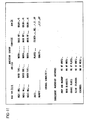
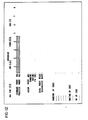
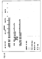
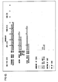
- Various messages are exchanged between the PMA and REC, most information flowing to the REC for filing. Table II illustrates the messages exchanged, the types of messages being as follows:

- Examples of the information content of these messages are as follows. In these examples a byte is eight bits (0000 0000) and large numbers are expressed in scientific (exponential) notation. Some information is expressed in ASCII Code, in which case one byte defines one letter of the code.


- In reporting dead blankets, only those blanket positions which have been changed are reported. Therefore, the number of dead blanket messages, and the humber of blankets reported in the last message, for any given change of blankets, will depend on the number of blankets changed.


- In some instances the messages themselves will indicate a unit of measurement in which a quantity is being expressed, but in other instances the unit may not be obvious from the message. By way of example, the following are some typical message fields, and the corresponding units of measurement:

- The following data will be accumulated for each interval:
- TIME (minutes)
- NET (impressions)
- WASTE (impressions)
- SPEED (impressions/hour)
-
NET LINEAR FEET 1 & 2 (feet) -
GROSS LINEAR FEET 1 & 2 (feet) - TIME is accumulated by incrementing a time count each minute that the interval is active. Other values are calculated at interval end according to these equations:
- Net Linear Feet interval=NET end-NET begin
- WASTE interval=GROSS end-GROSS begin-Net interval
- SPEED interval=((GROSS end-GROSS begin)/TIME)x60 or
- SPEED run interval=(NET interval/TIME)x60
- Net Linear Feet interval=NLF end-NLF begin
- Gross Linear Feet interval=GLF end-GLF begin.
- To enable calculation of the desired data, the PMA hardware provides storage of the following data for an interval:

- By the nature of press operations, and to allow future calculation of intervals not explicitly tracked-such as Printing Waste-three intervals can run concurrently:

- The PMA maintains three interval tracking areas-28 bytesx3=84 bytes.
- Data on intervals E1, E2, E3, E4, and DT are not sent at interval end as is data for the other intervals. In addition, intervals E1, E2, E3, and E4 may not be continuous, such that the final interval data must be a summation of interval segments data. To accommodate these requirements, the PMA data base provides eight internal save areas patterned after the interval message:


- There are a number of displays available at the PMA and the REC consoles, and these are listed below, together with appropriate Figure numbers of the drawings, which show the significant ones of the displays. The display menus for each are simply these listings of displays.

- A typical operation of the system involves the performance of at least one job by the press, and for purposes of explanation it will be assumed that the job is to begin with a new crew which is coming to work on a shift. Fig. 6 shows the regions on the CRT of the PMA console which are utilized for communication with the press crew, usually the crew chief. The largest center region, designated D is the region in which the various displays, appear, such as those shown in Fig. 12-20. The smaller border region to the top designated AL is used for alarm prompts, and in the preferred embodiment, since a color CRT is used, this region is surrounded by a red rectangle to draw the attention of the operator to the alarm prompt. The region at the bottom designated M, is used for reminder prompts to the operator, and other instructions during the function of the system, and in the preferred embodiment it is surrounded by a blue border.
- Assuming that the system has been started, and time and date has been entered in response to a Time Request Message via the clock and calendar in the REC (Table II), job standards can then be entered via the REC console by a management or supervisory person. The standards are stored in the disc memory and can merely be recalled and displayed at the REC console, or these may be changed if needed. Such standards are used as later explained. The REC to PMA Makeready Data message transfers the data to the PMA memory.
- At the beginning of a shift, the Crew Data display (Fig. 10) is called up on the CRT of one or the other console, appearing as a table with spaces to be filled in. An operator at that console enters the necessary data to identify the crew. For example, crew data will be input at the PMA during each operating shift, an identification number is provided for each member of the crew, and at appropriate times the entry device is also used to provide to the system the times when each particular member of the crew begins and ends his shift. A Crew LogOn Message is sent to the REC when the entries are completed at the PMA.
- A further display (Fig. 11) identifies and calls for information needed in association with makeready startup operations. This for example will include identification of the run and job, the number, types, sizes and other characteristics of webs to be used, the number of active printing units, usually related to the number of colors in a job, the number of plates to be used and any information concerning the folder or its operations. Also to be filled in are the number of units involved as concerned with preparation and washup, washing blankets, changing plates, cleaning cylinders, or leading one or more webs through the press. The REC display for Production Order is identical to the upper half of the PMA Makeready Startup display. Thus an order can be entered at either. It is also possible to have the order filed at the REC disc memory and recalled, in which case a Production Order message would be communicated to the PMA. The press crew chief can call up the completed Production Order to the PMA by entering "
DISPLAY 1 ENTER" and fill in the remainder. The system will not proceed until this information is complete. As soon as this information is completed by the entry process, the information is stored in memory via a Production Order message. Productivity calculations are made, using standard run constants which have been previously determined, based upon experience with the press or a like press. These constants are filed at the REC console, and of course are subject to change as more up to date information might be available to the production management office. - When the Production Order data is entered, the PMA computer calls up these constants and uses them to calculate the standard times. Typical constants filed at the REC are
- K1-Preparation & Washup-Minutes per fountains
- K2-Washing Blankets-Minutes per fountains
- K3-Changing Plates-Minutes per plate
- K4-Cleaning Cylinders & Bearers-Min. per fountain
- K5-Leading Web-Minutes per web
- K6-Impressions/hr-Imp/hr
- K7-% Running Waste-Waste/Good. The calculations made at the PMA are
- T1-Total Preparation & Wash Time K1 xNo. of fountains
- T2-Total Wash Blanket Time K2xNo. of fountains
- T3-Total Changing Plates K3xNo. of plates-
- T4-Total Cleaning Cylinders and Bearers K4xNo. of fountains
- T5-Total Leading Webs K5xNo. of webs.
- Calculations include
- Total Makeready Hours=TM=T1+T2+T3+T4+T5
- Standard Makeready Waste=TMXK7
- Standard Running Waste=Print QuantityxK7 .
- Standard Waste=Std. Makeready Waste+Std. Run Waste
- Standard Run Hours=Print Quantity=K6.
- When productivity calculations are completed the Makeready operation proceeds. Fig. 12 shows the Makeready display with only standard and projected makeready bar graphs. This display automatically appears, as soon as Production data is entered, and represents the situation at the beginning of phase I of the makeready period (MR 1). During this time the crew proceeds to hang plates, thread the webs, prepare (but not set) the ink fountains, etc.
- The system is monitoring progress during this period, and for every four minute (one fifteenth of an hour) an Event Message is sent to the REC, and also a graph increment is added where appropriate. As the makeready operation "proceeds another bar graph appears on the display, representing accumulated makeready hours. This bar, which grows in length as the makeready operation proceeds represents actual time elapsed from the beginning of phase I makeready, when this display appeared. Also on the display are places for entry for the amount of down time or waiting time for the press, or time required for management functions, and bar graphs showing, individually, accumulated down time, wait time and press management time.
- In connection with down time during makeready, the display includes provision for a number of down time operating codes which identify specific types of down time during the makeready process, and also a place to enter wait time and press management operating codes. The system will charge wait time unless an operator intervenes a particular operating code to identify a specific down time operation to which the elapsed time at this point should be allocated. The progress and/or stoppage of normal makeready results in Event messages, including time, operation identifying (OP) code and elapsed time or downtime, being sent regularly to the REC and recorded (filed), and also used to build the display graphs. The various events which lead to different press status are shown in Fig. 21 and can also be noted from Table I1, Message Exchange.
- When the crew has run some waste, phase II of makeready begins. This is recognized as event E5 (see Fig. 21) and the system then automatically updates the makeready display (Fig. 13), with its accumulated graphs. The state is now
MR 2, as shown in Fig. 21. The system, every four minutes calculates makeready projected time and this information is part of the PMA display. When makeready phase I is begun, the projected time is set equal to the standards, since no operations have occurred. Thereafter, the time associated with washing blankets, leading webs, washing up, and changing plates are all accumulated separately. This is accomplished by using the decoded sensor signals to direct clock information into appropriate time stores or registers, where time for the corresponding operation accumulates. In addition to the four operations just mentioned, there is also a register for storing time indicating merely that the operation has stopped. To calculate projected makeready time, the standard time for the particular operation is substituted until the operation is begun. Thereafter, the actual time spent in that operation is added. If an operation is in progress during the four minute update cycle, then the time for the operation is either the accumulated time before that operation, or the standard, whichever is greater. Once an operation is completed, the actual time is used unless that operation begins again. All projections that extend past a shift boundary (e.g. eight hours for a shift) are truncated so that the projected time becomes the time until the end of the shift. The mathematical presentation of this calculation, which is repeated every four minutes is as follows:
- Thus, PrMT=WBT+CPT+LWT+WUT+DT+WT+PM.
- As the phase I makeready proceeds, the projected makeready hours bar graph will appear less than the standard makeready hours bar (if the crew is ahead of normal schedule), or equal to standard if the crew is on normal schedule. An over standard situation is described below. If the makeready display remains on the PMA display CRT, the projected makeready hour bar will fluctuate vs. the standard according to the situation.
- The system also records a menu of operational (OP) codes and descriptive phrases which the operator can call upon demand should he not have the necessary code memorized at the time it is necessary to enter it at the console for some reason. The menu comprises two displays, Figs. 19 and 20, which the operator can recall and readily look up all the various identifications for operational codes necessary to allocate particular operations or occurrences within the term of the makeready and run operations.
- A typical makeready display is shown in Fig. 13, and includes some downtime and some accumulated waste. It is assumed here that the operator, during phase I makeready, has entered an appropriate OPCODE for the downtime reason (obtained from menu, Figs. 19 or 20, if necessary) and a message has been recorded at the REC. Only the totals are displayed here, not preceding reasons. Waste is represented as one unit (fifteen screen increments) per 4000 impressions.
- Fig. 14 shows the phase II makeready display at a later time. Some more downtime has occurred and the operator has determined it resulted from a web break at the upper infeed. He has entered the
OPCODE 540. The bar after this code was deleted once the press again was running and the downtime increased accordingly. The downtime event message has been reported to the REC file. It should also be noted that accumulated waste now equals 4000 impressions, almost one-fourth of the standard for makeready waste. - Fig. 15 shows the Makeready display later in phase II. A further downtime has been encountered which was detected and automatically entered as due to a web break in printing unit one,
OPCODE 542; Fig. 21, E8 transition fromMR 2 toMR 2 DOWN. After about thirty minutes this was manually terminated by the operator, who determined the actual cause of downtime was due to a mill splice break. He has therefore enteredOPCODE 435, and about one hour of downtime has accumulated for that reason. - At this point it should be noted that the latest calculation of projected makeready hours now exceeds the standard. The bar graph for projected makeready hours has therefore changed color, and it is expected that the makeready mode will require more than standard time before it is completed.
- It should also be noted that wait times and press management (PM) times are always manually entered OPCODES. When these are ended, the corresponding totalled bar graphs remain on the display until the makeready mode is complete.
- The operator, or the production manager if he calls up the Makeready display to the REC, can thus be continuously informed as to the progress of the makeready operation, and if there are any unexpected delays, they will likewise be informed as to the time and nature of these delays.
- Once the makeready process is completed, including leading webs and print registration, and the press is running, the operator will press the GOOD button on the PMA console to indicate that a "good count" has begun. This also indicates that the output of the folders is to be saved from that time on during the run, unless some intervening condition produces waste. When the operator thus signals the beginning of the good count, the PMA display automatically changes to the Run Status display (Fig. 16). It includes bar graphs of standard run hours, standard run waste, and a gradually increasing graph showing actual run hours. Additional graph bars can show down time hours, wait time hours, or management time hours during the term of the run. In the event of down time, wait time, or management time the operator can enter codes identifying the particular operation or occurrence from which the stoppage resulted, and this is automatically recorded at the REC along with the date and time of day, so that the occurrence, nature, and length of time of each of these nonproductive periods is recorded (filed).
- Similar to the makeready mode, projected run time is calculated and the "Projected Run Hours" display is updated every four minutes. This calculation is based on the difference between the target good count (QUANTITY) entered during makeready startup (Fig. 11) and the present good count. Initially the projection is set equal to the standard.
- As the run progresses, an effective printing rate (speed) is calculated every four minutes.

- Then the projected run time (PRT) is calculated as

- During down, wait, or press maintenance.time this calculation is not made. The projection is simply increased by four minute increments for the duration of the non-running period. Calculated projection begins again when the good event E6 is detected.
- Since presses of this type usually operate from a reel which allows the web from a new roll to be pasted to the end of the web from an exhausted roll (as above described), the system also provides for an accounting of waste resulting from the passage of the paste through the press. To accomplish this, the good counter, having been started by the operator as previously mentioned, is automatically turned off once a predetermined number of gross counts occur after sensing the paste. It is then up to the operator again to signal commencement of a good count as soon as the paste has cleared to the point that and good prints are again available.
- Fig. 17 shows the Run Status display after the run has progressed at a normal (standard) rate for about forty-five minutes. The projected run hours are equal to the standard. The standard run waste has been displayed, having been calculated from the standards information on file at the REC. Accumulated impression per hour (the Effective Printing Rate) is within standard, and as yet there has not been any run waste.
- Fig. 18 shows the display later on, after a little more than two hours run time. A wait is occurring for paper (OPCODE 605), run waste is still below standard, but the accumulated impressions per hour is now just under 24,000/hr, in excess of standard, and the projected run hours now exceeds standard, hence the bar graph for projected run hours has changed color.
- Referring again to Fig. 21, the diagram explains the overall press state sequences with event codes (E0E9) and keyboard derived events (C0-C7), referencing the press modes or states. These are Makeready (MR1 and MR2) and Run. Thus the system monitors, prompts, creates and updates displays, and otherwise assists the operating crew, while at the same time providing management information both dynamically and by building operations files which can be used to prepare various hard copy reports. Samples of two such reports are:
- a) Press Run Data Report-Table III, and
- b) Daily Production Report-Table IV.
- While the form of apparatus herein described constitutes a preferred embodiment of this invention, it is to be understood that the invention is not limited to this precise form of apparatus, and that changes may be made therein without departing from the scope of the invention which is defined in the appended claims.
- What is claimed is:


Claims (13)
Applications Claiming Priority (2)
| Application Number | Priority Date | Filing Date | Title |
|---|---|---|---|
| US06/133,770 US4346446A (en) | 1980-03-25 | 1980-03-25 | Management and analysis system for web machines and the like |
| US133770 | 1980-03-25 |
Publications (3)
| Publication Number | Publication Date |
|---|---|
| EP0048265A1 EP0048265A1 (en) | 1982-03-31 |
| EP0048265A4 EP0048265A4 (en) | 1983-07-04 |
| EP0048265B1 true EP0048265B1 (en) | 1986-08-13 |
Family
ID=22460232
Family Applications (1)
| Application Number | Title | Priority Date | Filing Date |
|---|---|---|---|
| EP81900917A Expired EP0048265B1 (en) | 1980-03-25 | 1981-03-24 | Method of operating a web processing apparatus and web processing apparatus |
Country Status (4)
| Country | Link |
|---|---|
| US (1) | US4346446A (en) |
| EP (1) | EP0048265B1 (en) |
| JP (1) | JPS57500427A (en) |
| WO (1) | WO1981002799A1 (en) |
Families Citing this family (76)
| Publication number | Priority date | Publication date | Assignee | Title |
|---|---|---|---|---|
| US4495582A (en) * | 1982-06-04 | 1985-01-22 | Harris Graphics Corporation | Control system for pre-setting and operation of a printing press and collator |
| US4839814A (en) * | 1985-01-29 | 1989-06-13 | Moore Business Forms, Inc. | Size independent modular web processing line and modules |
| FR2584214B1 (en) * | 1985-06-28 | 1987-09-25 | Valois Dominique | METHOD FOR DISPLAYING INFORMATION RELATING TO THE PRODUCTION OF ARTICLES. |
| JPS6262762A (en) * | 1985-09-12 | 1987-03-19 | Tokyo Kikai Seisakusho:Kk | Production step managing system for newspaper printing |
| JPH01106111A (en) * | 1987-10-19 | 1989-04-24 | Fuji Photo Film Co Ltd | Sequence monitoring method |
| DE3708925C2 (en) * | 1986-04-30 | 1995-08-31 | Heidelberger Druckmasch Ag | Device for controlling or regulating operations on a rotary offset sheet-fed printing press |
| US4835699A (en) * | 1987-03-23 | 1989-05-30 | Burlington Industries, Inc. | Automated distributed control system for a weaving mill |
| US4984773A (en) * | 1987-10-06 | 1991-01-15 | Rockwell International Corporation | Method of and apparatus for composing a press imposition |
| US4980846A (en) * | 1988-04-07 | 1990-12-25 | Impact Systems, Inc. | Process and apparatus for controlling on-line a parameter of a moving sheet |
| WO1990012375A1 (en) * | 1989-04-11 | 1990-10-18 | Mobil Oil (Switzerland) | Maintenance monitoring system |
| US5134574A (en) * | 1990-02-27 | 1992-07-28 | The Foxboro Company | Performance control apparatus and method in a processing plant |
| US5043904A (en) * | 1990-04-27 | 1991-08-27 | Web Printing Controls Co., Inc. | Web handling apparatus monitoring system with user defined outputs |
| US5216612A (en) * | 1990-07-16 | 1993-06-01 | R. J. Reynolds Tobacco Company | Intelligent computer integrated maintenance system and method |
| US5155693A (en) * | 1990-09-05 | 1992-10-13 | Hewlett-Packard Company | Self documenting record of instrument activity and error messages stamped with date and time of occurrence |
| US5260878A (en) * | 1991-09-06 | 1993-11-09 | Automation, Inc. | Web press monitoring system |
| DE4133980A1 (en) * | 1991-10-14 | 1993-04-15 | Siemens Ag | AUTOMATIC CONTROL FOR A POWER PLANT |
| US5408590A (en) * | 1991-12-09 | 1995-04-18 | Domino Amjet, Inc. | Direct ink drop interface board |
| US5559710A (en) * | 1993-02-05 | 1996-09-24 | Siemens Corporate Research, Inc. | Apparatus for control and evaluation of pending jobs in a factory |
| US5379211A (en) * | 1993-05-11 | 1995-01-03 | Brown Printing Company, A Division Of Gruner & Jahr Printing And Publishing Co. | Press folder preset system |
| US5521844A (en) * | 1993-09-10 | 1996-05-28 | Beloit Corporation | Printing press monitoring and advising system |
| CA2123245A1 (en) | 1993-09-29 | 1995-03-30 | Alan F. Barney | System for controlling printing press and accessories and auxiliaries therefor |
| US6507832B1 (en) * | 1994-02-15 | 2003-01-14 | R.R. Donnelley & Sons Company | Using ink temperature gain to identify causes of web breaks in a printing system |
| US5469362A (en) * | 1994-05-16 | 1995-11-21 | Pitney Bowes Inc. | Dispatching method and apparatus for monitoring scheduled mail |
| EP0763184A1 (en) * | 1994-06-01 | 1997-03-19 | Stridsberg Innovation Ab | Position transducer |
| JP3085095B2 (en) * | 1994-07-25 | 2000-09-04 | 株式会社日立製作所 | Plant monitoring device and monitoring method |
| KR970010375B1 (en) * | 1994-10-31 | 1997-06-25 | 삼성전자 주식회사 | Band printing method which protects band overrun error in page printer |
| US5548535A (en) * | 1994-11-08 | 1996-08-20 | Advanced Micro Devices, Inc. | Monitor utility for use in manufacturing environment |
| JP3509964B2 (en) * | 1994-11-22 | 2004-03-22 | 株式会社アマダ | Operation recording method and recording device for NC processing machine |
| DE19505692A1 (en) * | 1995-02-20 | 1996-08-22 | Roland Man Druckmasch | Printing press |
| US5896292A (en) * | 1995-06-05 | 1999-04-20 | Canon Kabushiki Kaisha | Automated system for production facility |
| US6952801B2 (en) * | 1995-06-07 | 2005-10-04 | R.R. Donnelley | Book assembly process and apparatus for variable imaging system |
| US5946661A (en) * | 1995-10-05 | 1999-08-31 | Maxager Technology, Inc. | Method and apparatus for identifying and obtaining bottleneck cost information |
| US5923834A (en) * | 1996-06-17 | 1999-07-13 | Xerox Corporation | Machine dedicated monitor, predictor, and diagnostic server |
| DE19628078C2 (en) * | 1996-07-12 | 2001-04-05 | Roland Man Druckmasch | Method and device for determining time-related print production data for a printing press |
| US6032122A (en) * | 1997-03-14 | 2000-02-29 | Bell & Howell Mail And Messaging Technologies Company | Systems, methods and computer program products for monitoring and controlling mail processing devices |
| US6246993B1 (en) * | 1997-10-29 | 2001-06-12 | R. R. Donnelly & Sons Company | Reorder system for use with an electronic printing press |
| US6049775A (en) * | 1998-01-30 | 2000-04-11 | Bell & Howell Mail And Messaging Technologies Company | Systems, methods and computer program products for monitoring and controlling mail processing devices |
| US6157916A (en) * | 1998-06-17 | 2000-12-05 | The Hoffman Group | Method and apparatus to control the operating speed of a papermaking facility |
| US7319965B1 (en) | 1998-06-17 | 2008-01-15 | The Hoffman Group | Method and apparatus to control the operating speed of a manufacturing facility |
| DE59901334D1 (en) * | 1998-07-18 | 2002-06-06 | Roland Man Druckmasch | Maintenance and inspection system for a printing press |
| US6321287B1 (en) | 1998-10-19 | 2001-11-20 | Dell Usa, L.P. | Console redirection for a computer system |
| US6408334B1 (en) | 1999-01-13 | 2002-06-18 | Dell Usa, L.P. | Communications system for multiple computer system management circuits |
| US7278094B1 (en) | 2000-05-03 | 2007-10-02 | R. R. Donnelley & Sons Co. | Variable text processing for an electronic press |
| US6625567B1 (en) * | 1999-11-04 | 2003-09-23 | Bell & Howell Messaging Technologies Company | Automated methods and systems for analyzing data associated with an industrial process |
| CZ303371B6 (en) * | 2000-11-15 | 2012-08-22 | Heidelberger Druckmaschinen Ag | Method for transmitting operational data of a printing machine |
| US6988349B2 (en) * | 2000-12-27 | 2006-01-24 | Pitney Bowes Inc. | Printstream processing for inserter systems |
| US20030023408A1 (en) * | 2001-03-06 | 2003-01-30 | Robin Wight | System for collecting and storing information |
| JP2004341695A (en) * | 2003-05-14 | 2004-12-02 | Konica Minolta Photo Imaging Inc | Display system |
| US7205185B2 (en) * | 2003-09-15 | 2007-04-17 | International Busniess Machines Corporation | Self-aligned planar double-gate process by self-aligned oxidation |
| US7287473B2 (en) * | 2005-12-20 | 2007-10-30 | Heidelberger Druckmaschinen Ag | Method for selecting printing material in a printing press and printing press |
| US9131548B2 (en) * | 2006-02-09 | 2015-09-08 | Production Resource Group, Llc | Test machine for an automated light |
| DE102006027092A1 (en) * | 2006-06-10 | 2007-12-13 | Man Roland Druckmaschinen Ag | Method for recording operating data on machines used in the printing industry, in particular on printing machines |
| DE102006043422A1 (en) * | 2006-07-27 | 2008-01-31 | Koenig & Bauer Aktiengesellschaft | Material web preparation method, involves preparing material web, in which section slant is formed at sides directed in longitudinal direction, where reinforcing strip is placed in border area of section beveled parallel to edge of beveling |
| US7765926B2 (en) * | 2007-02-08 | 2010-08-03 | Goss International Americas, Inc. | Web printing press with delivery stream length determination |
| US8733249B2 (en) * | 2007-02-20 | 2014-05-27 | Goss International Americas, Inc. | Real-time print product status |
| US11269303B2 (en) | 2009-06-22 | 2022-03-08 | Johnson Controls Technology Company | Systems and methods for detecting changes in energy usage in a building |
| US8532839B2 (en) | 2009-06-22 | 2013-09-10 | Johnson Controls Technology Company | Systems and methods for statistical control and fault detection in a building management system |
| US9753455B2 (en) | 2009-06-22 | 2017-09-05 | Johnson Controls Technology Company | Building management system with fault analysis |
| US8788097B2 (en) * | 2009-06-22 | 2014-07-22 | Johnson Controls Technology Company | Systems and methods for using rule-based fault detection in a building management system |
| US10739741B2 (en) | 2009-06-22 | 2020-08-11 | Johnson Controls Technology Company | Systems and methods for detecting changes in energy usage in a building |
| US9196009B2 (en) | 2009-06-22 | 2015-11-24 | Johnson Controls Technology Company | Systems and methods for detecting changes in energy usage in a building |
| US8731724B2 (en) | 2009-06-22 | 2014-05-20 | Johnson Controls Technology Company | Automated fault detection and diagnostics in a building management system |
| US9606520B2 (en) | 2009-06-22 | 2017-03-28 | Johnson Controls Technology Company | Automated fault detection and diagnostics in a building management system |
| US9286582B2 (en) | 2009-06-22 | 2016-03-15 | Johnson Controls Technology Company | Systems and methods for detecting changes in energy usage in a building |
| US8532808B2 (en) | 2009-06-22 | 2013-09-10 | Johnson Controls Technology Company | Systems and methods for measuring and verifying energy savings in buildings |
| US8600556B2 (en) | 2009-06-22 | 2013-12-03 | Johnson Controls Technology Company | Smart building manager |
| DE102011008592B4 (en) * | 2010-02-08 | 2022-08-18 | Heidelberger Druckmaschinen Ag | Color control for printing presses with short inking units |
| EP2517883B1 (en) * | 2011-04-28 | 2018-10-17 | Heidelberger Druckmaschinen AG | Method for operating a printing machine |
| US9390388B2 (en) | 2012-05-31 | 2016-07-12 | Johnson Controls Technology Company | Systems and methods for measuring and verifying energy usage in a building |
| DE102013108829B4 (en) * | 2013-05-13 | 2019-03-28 | Windmöller & Hölscher Kg | Roller handling system for a winder and method therefor |
| EP2826626B1 (en) * | 2013-07-15 | 2016-01-20 | Goss Contiweb B.V. | Web break analysis system |
| DE102013108104B4 (en) * | 2013-07-29 | 2019-10-17 | Windmöller & Hölscher Kg | Method and control device for controlling a winding device |
| US9778639B2 (en) | 2014-12-22 | 2017-10-03 | Johnson Controls Technology Company | Systems and methods for adaptively updating equipment models |
| CN105252895B (en) * | 2015-11-06 | 2018-02-23 | 常德金鹏印务有限公司 | A kind of sheet-fed Rotary Postpress and Print Finishing |
| JP2018045395A (en) * | 2016-09-13 | 2018-03-22 | 株式会社ジェイテクト | Education support device |
| US11556867B2 (en) * | 2019-10-16 | 2023-01-17 | Caterpillar Inc. | System and method for worksite project tracking |
Family Cites Families (7)
| Publication number | Priority date | Publication date | Assignee | Title |
|---|---|---|---|---|
| US4195338A (en) * | 1970-05-06 | 1980-03-25 | Bell Telephone Laboratories, Incorporated | Computer typesetting |
| US3930145A (en) * | 1973-05-07 | 1975-12-30 | Geophysical Systems Corp | Data acquisition and processing system |
| JPS5434501B2 (en) * | 1974-02-15 | 1979-10-27 | ||
| US3946211A (en) * | 1974-07-17 | 1976-03-23 | Leeds & Northrup Company | Amplitude limited filter |
| FR2335000A1 (en) * | 1975-12-09 | 1977-07-08 | Stofa Mobila Intreprinderea | PROCESS AND INSTALLATION FOR THE AUTOMATIC TRACKING, CONTROL AND SYNTHESIS OF PRODUCTION PARAMETERS |
| GB2024457B (en) * | 1978-06-07 | 1983-01-06 | Harris Corp | Printing press ready and control system |
| JPS55137972A (en) * | 1979-04-14 | 1980-10-28 | Dainippon Printing Co Ltd | Checking system of operational condition for printing machine |
-
1980
- 1980-03-25 US US06/133,770 patent/US4346446A/en not_active Expired - Lifetime
-
1981
- 1981-03-24 JP JP56501303A patent/JPS57500427A/ja active Pending
- 1981-03-24 WO PCT/US1981/000366 patent/WO1981002799A1/en active IP Right Grant
- 1981-03-24 EP EP81900917A patent/EP0048265B1/en not_active Expired
Non-Patent Citations (3)
| Title |
|---|
| Computer, Oct. 1975, page 55 * |
| Hilberg Piloty "Mikroprozessoren und ihre Anwendungen 1977, pp. 184-187 * |
| Kusol "Technik der Prozessdatenverarbeitung, 1973, pp. 12,17,18,103-105 * |
Also Published As
| Publication number | Publication date |
|---|---|
| EP0048265A4 (en) | 1983-07-04 |
| EP0048265A1 (en) | 1982-03-31 |
| WO1981002799A1 (en) | 1981-10-01 |
| US4346446A (en) | 1982-08-24 |
| JPS57500427A (en) | 1982-03-11 |
Similar Documents
| Publication | Publication Date | Title |
|---|---|---|
| EP0048265B1 (en) | Method of operating a web processing apparatus and web processing apparatus | |
| CA1187193A (en) | Forms manufacturing system | |
| CA1309762C (en) | Printing machine control system | |
| DE3204325C2 (en) | ||
| US5870696A (en) | Method and apparatus for monitoring and recording real time data of a paper printing production machine | |
| JP2000351201A (en) | Apparatus for controlling printing machine | |
| EP0160167A1 (en) | Method and apparatus for distributed electronic control of a printing press | |
| DE112009003661T5 (en) | Performance monitoring device, performance monitoring method and device for mounting a component | |
| DE4329886B4 (en) | Sequencing system for printing companies | |
| EP1864807A2 (en) | Method for logging operating data in machines used in the printing industry, in particular in printing presses | |
| DE4013286C2 (en) | Control for multiple presses in a press room | |
| EP0818310B1 (en) | Data acquisition system and method for printing press | |
| JPH0811294A (en) | Work control apparatus | |
| JPH0348032B2 (en) | ||
| JP2812694B2 (en) | Machine operation status monitoring device | |
| JPH09319620A (en) | Operation monitoring system for automatic certificate issue machine | |
| JPH04371843A (en) | Web material process management device | |
| US20070169649A1 (en) | Press operation and management information system for offset sheet fed printing industry | |
| JPH04126188A (en) | Sewing process control system | |
| SU363109A1 (en) | DEVICE FOR CONTROL AND ACCOUNTING OF PRODUCTION PROCESSES | |
| JPH0322313B2 (en) | ||
| KR920006897Y1 (en) | System for producting management | |
| JPH0756620A (en) | Working controller for production equipment | |
| JPH01229634A (en) | Set number command device | |
| JPH0447859B2 (en) |
Legal Events
| Date | Code | Title | Description |
|---|---|---|---|
| PUAI | Public reference made under article 153(3) epc to a published international application that has entered the european phase |
Free format text: ORIGINAL CODE: 0009012 |
|
| AK | Designated contracting states |
Designated state(s): DE FR GB SE |
|
| 17P | Request for examination filed |
Effective date: 19820303 |
|
| RAP1 | Party data changed (applicant data changed or rights of an application transferred) |
Owner name: HARRIS GRAPHICS CORPORATION |
|
| GRAA | (expected) grant |
Free format text: ORIGINAL CODE: 0009210 |
|
| AK | Designated contracting states |
Kind code of ref document: B1 Designated state(s): DE FR GB SE |
|
| PG25 | Lapsed in a contracting state [announced via postgrant information from national office to epo] |
Ref country code: SE Effective date: 19860831 |
|
| REF | Corresponds to: |
Ref document number: 3175095 Country of ref document: DE Date of ref document: 19860918 |
|
| ET | Fr: translation filed | ||
| PLBE | No opposition filed within time limit |
Free format text: ORIGINAL CODE: 0009261 |
|
| STAA | Information on the status of an ep patent application or granted ep patent |
Free format text: STATUS: NO OPPOSITION FILED WITHIN TIME LIMIT |
|
| 26N | No opposition filed | ||
| PGFP | Annual fee paid to national office [announced via postgrant information from national office to epo] |
Ref country code: SE Payment date: 19890315 Year of fee payment: 9 |
|
| PG25 | Lapsed in a contracting state [announced via postgrant information from national office to epo] |
Ref country code: GB Effective date: 19890324 |
|
| PGFP | Annual fee paid to national office [announced via postgrant information from national office to epo] |
Ref country code: DE Payment date: 19890331 Year of fee payment: 9 |
|
| GBPC | Gb: european patent ceased through non-payment of renewal fee | ||
| PG25 | Lapsed in a contracting state [announced via postgrant information from national office to epo] |
Ref country code: DE Effective date: 19901201 |
|
| PGFP | Annual fee paid to national office [announced via postgrant information from national office to epo] |
Ref country code: FR Payment date: 19920306 Year of fee payment: 12 |
|
| PG25 | Lapsed in a contracting state [announced via postgrant information from national office to epo] |
Ref country code: FR Effective date: 19931130 |
|
| REG | Reference to a national code |
Ref country code: FR Ref legal event code: ST |