EP0047089A1 - Method of and apparatus for controlling loads on an electrical power supply - Google Patents
Method of and apparatus for controlling loads on an electrical power supply Download PDFInfo
- Publication number
- EP0047089A1 EP0047089A1 EP81303720A EP81303720A EP0047089A1 EP 0047089 A1 EP0047089 A1 EP 0047089A1 EP 81303720 A EP81303720 A EP 81303720A EP 81303720 A EP81303720 A EP 81303720A EP 0047089 A1 EP0047089 A1 EP 0047089A1
- Authority
- EP
- European Patent Office
- Prior art keywords
- supply
- load
- signal
- predetermined
- loads
- Prior art date
- Legal status (The legal status is an assumption and is not a legal conclusion. Google has not performed a legal analysis and makes no representation as to the accuracy of the status listed.)
- Granted
Links
Images

Classifications
-
- H—ELECTRICITY
- H02—GENERATION; CONVERSION OR DISTRIBUTION OF ELECTRIC POWER
- H02J—CIRCUIT ARRANGEMENTS OR SYSTEMS FOR SUPPLYING OR DISTRIBUTING ELECTRIC POWER; SYSTEMS FOR STORING ELECTRIC ENERGY
- H02J13/00—Circuit arrangements for providing remote indication of network conditions, e.g. an instantaneous record of the open or closed condition of each circuitbreaker in the network; Circuit arrangements for providing remote control of switching means in a power distribution network, e.g. switching in and out of current consumers by using a pulse code signal carried by the network
- H02J13/00006—Circuit arrangements for providing remote indication of network conditions, e.g. an instantaneous record of the open or closed condition of each circuitbreaker in the network; Circuit arrangements for providing remote control of switching means in a power distribution network, e.g. switching in and out of current consumers by using a pulse code signal carried by the network characterised by information or instructions transport means between the monitoring, controlling or managing units and monitored, controlled or operated power network element or electrical equipment
- H02J13/00007—Circuit arrangements for providing remote indication of network conditions, e.g. an instantaneous record of the open or closed condition of each circuitbreaker in the network; Circuit arrangements for providing remote control of switching means in a power distribution network, e.g. switching in and out of current consumers by using a pulse code signal carried by the network characterised by information or instructions transport means between the monitoring, controlling or managing units and monitored, controlled or operated power network element or electrical equipment using the power network as support for the transmission
- H02J13/0001—Circuit arrangements for providing remote indication of network conditions, e.g. an instantaneous record of the open or closed condition of each circuitbreaker in the network; Circuit arrangements for providing remote control of switching means in a power distribution network, e.g. switching in and out of current consumers by using a pulse code signal carried by the network characterised by information or instructions transport means between the monitoring, controlling or managing units and monitored, controlled or operated power network element or electrical equipment using the power network as support for the transmission using modification of a parameter of the network power signal
-
- H—ELECTRICITY
- H02—GENERATION; CONVERSION OR DISTRIBUTION OF ELECTRIC POWER
- H02J—CIRCUIT ARRANGEMENTS OR SYSTEMS FOR SUPPLYING OR DISTRIBUTING ELECTRIC POWER; SYSTEMS FOR STORING ELECTRIC ENERGY
- H02J13/00—Circuit arrangements for providing remote indication of network conditions, e.g. an instantaneous record of the open or closed condition of each circuitbreaker in the network; Circuit arrangements for providing remote control of switching means in a power distribution network, e.g. switching in and out of current consumers by using a pulse code signal carried by the network
- H02J13/00006—Circuit arrangements for providing remote indication of network conditions, e.g. an instantaneous record of the open or closed condition of each circuitbreaker in the network; Circuit arrangements for providing remote control of switching means in a power distribution network, e.g. switching in and out of current consumers by using a pulse code signal carried by the network characterised by information or instructions transport means between the monitoring, controlling or managing units and monitored, controlled or operated power network element or electrical equipment
- H02J13/00007—Circuit arrangements for providing remote indication of network conditions, e.g. an instantaneous record of the open or closed condition of each circuitbreaker in the network; Circuit arrangements for providing remote control of switching means in a power distribution network, e.g. switching in and out of current consumers by using a pulse code signal carried by the network characterised by information or instructions transport means between the monitoring, controlling or managing units and monitored, controlled or operated power network element or electrical equipment using the power network as support for the transmission
- H02J13/00009—Circuit arrangements for providing remote indication of network conditions, e.g. an instantaneous record of the open or closed condition of each circuitbreaker in the network; Circuit arrangements for providing remote control of switching means in a power distribution network, e.g. switching in and out of current consumers by using a pulse code signal carried by the network characterised by information or instructions transport means between the monitoring, controlling or managing units and monitored, controlled or operated power network element or electrical equipment using the power network as support for the transmission using pulsed signals
-
- H—ELECTRICITY
- H02—GENERATION; CONVERSION OR DISTRIBUTION OF ELECTRIC POWER
- H02J—CIRCUIT ARRANGEMENTS OR SYSTEMS FOR SUPPLYING OR DISTRIBUTING ELECTRIC POWER; SYSTEMS FOR STORING ELECTRIC ENERGY
- H02J3/00—Circuit arrangements for ac mains or ac distribution networks
- H02J3/12—Circuit arrangements for ac mains or ac distribution networks for adjusting voltage in ac networks by changing a characteristic of the network load
- H02J3/14—Circuit arrangements for ac mains or ac distribution networks for adjusting voltage in ac networks by changing a characteristic of the network load by switching loads on to, or off from, network, e.g. progressively balanced loading
- H02J3/144—Demand-response operation of the power transmission or distribution network
-
- H—ELECTRICITY
- H02—GENERATION; CONVERSION OR DISTRIBUTION OF ELECTRIC POWER
- H02J—CIRCUIT ARRANGEMENTS OR SYSTEMS FOR SUPPLYING OR DISTRIBUTING ELECTRIC POWER; SYSTEMS FOR STORING ELECTRIC ENERGY
- H02J2310/00—The network for supplying or distributing electric power characterised by its spatial reach or by the load
- H02J2310/50—The network for supplying or distributing electric power characterised by its spatial reach or by the load for selectively controlling the operation of the loads
- H02J2310/54—The network for supplying or distributing electric power characterised by its spatial reach or by the load for selectively controlling the operation of the loads according to a pre-established time schedule
-
- H—ELECTRICITY
- H02—GENERATION; CONVERSION OR DISTRIBUTION OF ELECTRIC POWER
- H02J—CIRCUIT ARRANGEMENTS OR SYSTEMS FOR SUPPLYING OR DISTRIBUTING ELECTRIC POWER; SYSTEMS FOR STORING ELECTRIC ENERGY
- H02J2310/00—The network for supplying or distributing electric power characterised by its spatial reach or by the load
- H02J2310/50—The network for supplying or distributing electric power characterised by its spatial reach or by the load for selectively controlling the operation of the loads
- H02J2310/56—The network for supplying or distributing electric power characterised by its spatial reach or by the load for selectively controlling the operation of the loads characterised by the condition upon which the selective controlling is based
- H02J2310/58—The condition being electrical
- H02J2310/60—Limiting power consumption in the network or in one section of the network, e.g. load shedding or peak shaving
-
- Y—GENERAL TAGGING OF NEW TECHNOLOGICAL DEVELOPMENTS; GENERAL TAGGING OF CROSS-SECTIONAL TECHNOLOGIES SPANNING OVER SEVERAL SECTIONS OF THE IPC; TECHNICAL SUBJECTS COVERED BY FORMER USPC CROSS-REFERENCE ART COLLECTIONS [XRACs] AND DIGESTS
- Y02—TECHNOLOGIES OR APPLICATIONS FOR MITIGATION OR ADAPTATION AGAINST CLIMATE CHANGE
- Y02B—CLIMATE CHANGE MITIGATION TECHNOLOGIES RELATED TO BUILDINGS, e.g. HOUSING, HOUSE APPLIANCES OR RELATED END-USER APPLICATIONS
- Y02B70/00—Technologies for an efficient end-user side electric power management and consumption
- Y02B70/30—Systems integrating technologies related to power network operation and communication or information technologies for improving the carbon footprint of the management of residential or tertiary loads, i.e. smart grids as climate change mitigation technology in the buildings sector, including also the last stages of power distribution and the control, monitoring or operating management systems at local level
- Y02B70/3225—Demand response systems, e.g. load shedding, peak shaving
-
- Y—GENERAL TAGGING OF NEW TECHNOLOGICAL DEVELOPMENTS; GENERAL TAGGING OF CROSS-SECTIONAL TECHNOLOGIES SPANNING OVER SEVERAL SECTIONS OF THE IPC; TECHNICAL SUBJECTS COVERED BY FORMER USPC CROSS-REFERENCE ART COLLECTIONS [XRACs] AND DIGESTS
- Y02—TECHNOLOGIES OR APPLICATIONS FOR MITIGATION OR ADAPTATION AGAINST CLIMATE CHANGE
- Y02B—CLIMATE CHANGE MITIGATION TECHNOLOGIES RELATED TO BUILDINGS, e.g. HOUSING, HOUSE APPLIANCES OR RELATED END-USER APPLICATIONS
- Y02B90/00—Enabling technologies or technologies with a potential or indirect contribution to GHG emissions mitigation
- Y02B90/20—Smart grids as enabling technology in buildings sector
-
- Y—GENERAL TAGGING OF NEW TECHNOLOGICAL DEVELOPMENTS; GENERAL TAGGING OF CROSS-SECTIONAL TECHNOLOGIES SPANNING OVER SEVERAL SECTIONS OF THE IPC; TECHNICAL SUBJECTS COVERED BY FORMER USPC CROSS-REFERENCE ART COLLECTIONS [XRACs] AND DIGESTS
- Y02—TECHNOLOGIES OR APPLICATIONS FOR MITIGATION OR ADAPTATION AGAINST CLIMATE CHANGE
- Y02E—REDUCTION OF GREENHOUSE GAS [GHG] EMISSIONS, RELATED TO ENERGY GENERATION, TRANSMISSION OR DISTRIBUTION
- Y02E60/00—Enabling technologies; Technologies with a potential or indirect contribution to GHG emissions mitigation
-
- Y—GENERAL TAGGING OF NEW TECHNOLOGICAL DEVELOPMENTS; GENERAL TAGGING OF CROSS-SECTIONAL TECHNOLOGIES SPANNING OVER SEVERAL SECTIONS OF THE IPC; TECHNICAL SUBJECTS COVERED BY FORMER USPC CROSS-REFERENCE ART COLLECTIONS [XRACs] AND DIGESTS
- Y04—INFORMATION OR COMMUNICATION TECHNOLOGIES HAVING AN IMPACT ON OTHER TECHNOLOGY AREAS
- Y04S—SYSTEMS INTEGRATING TECHNOLOGIES RELATED TO POWER NETWORK OPERATION, COMMUNICATION OR INFORMATION TECHNOLOGIES FOR IMPROVING THE ELECTRICAL POWER GENERATION, TRANSMISSION, DISTRIBUTION, MANAGEMENT OR USAGE, i.e. SMART GRIDS
- Y04S20/00—Management or operation of end-user stationary applications or the last stages of power distribution; Controlling, monitoring or operating thereof
- Y04S20/20—End-user application control systems
- Y04S20/222—Demand response systems, e.g. load shedding, peak shaving
-
- Y—GENERAL TAGGING OF NEW TECHNOLOGICAL DEVELOPMENTS; GENERAL TAGGING OF CROSS-SECTIONAL TECHNOLOGIES SPANNING OVER SEVERAL SECTIONS OF THE IPC; TECHNICAL SUBJECTS COVERED BY FORMER USPC CROSS-REFERENCE ART COLLECTIONS [XRACs] AND DIGESTS
- Y04—INFORMATION OR COMMUNICATION TECHNOLOGIES HAVING AN IMPACT ON OTHER TECHNOLOGY AREAS
- Y04S—SYSTEMS INTEGRATING TECHNOLOGIES RELATED TO POWER NETWORK OPERATION, COMMUNICATION OR INFORMATION TECHNOLOGIES FOR IMPROVING THE ELECTRICAL POWER GENERATION, TRANSMISSION, DISTRIBUTION, MANAGEMENT OR USAGE, i.e. SMART GRIDS
- Y04S40/00—Systems for electrical power generation, transmission, distribution or end-user application management characterised by the use of communication or information technologies, or communication or information technology specific aspects supporting them
- Y04S40/12—Systems for electrical power generation, transmission, distribution or end-user application management characterised by the use of communication or information technologies, or communication or information technology specific aspects supporting them characterised by data transport means between the monitoring, controlling or managing units and monitored, controlled or operated electrical equipment
- Y04S40/121—Systems for electrical power generation, transmission, distribution or end-user application management characterised by the use of communication or information technologies, or communication or information technology specific aspects supporting them characterised by data transport means between the monitoring, controlling or managing units and monitored, controlled or operated electrical equipment using the power network as support for the transmission
Definitions
- This invention relates to methods of and apparatus for controlling loads on an electrical power supply.
- control of individual loads may be desired by a consumer in order to keep within a predetermined maximum overall demand. It may also be desirable however to enable a utility to effect load shedding by disconnection of individual loads in accordance with a predetermined priority instead of having to disconnect supply circuits with the resultant complete interruption of all the supply to some consumers.
- a method of controlling loads on an alternating electrical power supply comprises the steps of modifying the alternating waveform of the supply to provide detectable controls signals of a plurality of distinguishably different forms, and, at each individual load to be controlled, detecting and selecting received signals of one of the distinguishably different forms and controlling the supply in accordance with the detected and selected signal.
- control signals can be signalled over the supply network but each individual load will only respond to a specific distinguishable signal. There is thus no need for any separate signalling system.
- the distinguishable signals might, for example, call for differing levels of maximum demand or load.
- individual appliances would have means for detecting and distinguishing between different signals.
- Each of said distinguishably different signals may comprise one or a sequence of similar waveform modifications which are distinguishable by the number of waveform modifications in the sequence, and, at the individual load to be controlled, the signals are distinguished by counting the number of waveform modifications received.
- control is to be by the utility, it is convenient to switch each individual load off for a predetermined period (e.g. 15 or 30 minutes) when the count at that load reaches a predetermined number.
- the means for detecting and selecting the appropriate signal may be reset during or at the end of said predetermined period.
- a method of controlling individual loads on an alternating electrical power supply comprises the steps of monitoring the overall demand, modifying the alternating waveform to provide a signal representative of the overall energy supply when that exceeds a predetermined limit, and, at each appliance to be controlled or associated with the individual supply circuit thereto, detecting said signal, incrementing the count on a counter on detection of said signal, decrementing the count on the counter in the absence of a further signal after a predetermined time, and switching off the individual load, or a part thereof, when the count in the counter exceeds a predetermined value.
- this method of control enables an individual consumer to pre-program his separate loads, e.g. individual appliances,in a predetermined priority order for the purpose of keeping his overall demand within a predetermined limit.
- the first appliance that is to say the appliance of lowest priority
- the means sensing the total demand will send out a further signal.
- the counters in the various appliances will then be incremented a second time and the appliance of the second lowest priority will be switched off. Any number of appliances may be controlled in this way by the transmission of successive signals.
- the cycle time for the signals might be of the order of 7.5 sec.
- the decrementing of the counter should occur only when the overall demand is some predetermined value (which would depend on the loads taken by individual appliances but which might typically be of the order of 3 kW or 6 kW) below said predetermined limit.
- said signal should be representative of the instantaneous energy consumption and that, at or associated with each individual load,this signal is detected and that the counter is decremented only when the instantaneous energy consumption is less than the predetermined maximum limit by said predetermined value.
- the signal for this purpose, conveniently consists of an interruption in the waveform of a duration substantially less than a cycle of the alternating power supply, the duration being a measure of the magnitude information to be transmitted, i.e. the rate of energy consumption. Conveniently this is achieved by switching off the supply, using a solid state switch, immediately before the zero crossing of the voltage waveform (or current waveform) and switching on again a short time later, the duration of the interruption being small compared with the time duration of a cycle at the supply frequency.
- the maximum duration of the interruption might be of the order of 20 or 30 0 of phase angle, that is to say 1.0 to 1.7 ms for a 50 Hz supply and slightly shorter for a 60 Hz supply.
- the unit At each unit, if the count on the counter corresponds to the priority of that unit the unit will be switched.off. It will remain switched off until the total current demand by the consumer is less than the maximum by an amount more than the appliance load; the counter will be decremented then and the appliance switched on.
- the invention also includes within its scope apparatus for controlling loads on one alternating electrical power supply comprising means, at each individual load to be controlled, for distinguishing one out of a plurality of different signals broadcast over the supply network as distinguishable modifications of the supply waveform and interrupting the supply to the load when a selected signal is received.
- apparatus for controlling loads on an alternating electrical power supply comprises means, at each individual load to be controlled, for detecting and counting the number of signals received as detectable modifications of the supply waveform and means controlling the supply to the load in accordance with the magnitude of the count.
- the means controlling the supply to the load may comprise means comparing the counted number of received signals with a predetermined number and operative to actuate switching means, conveniently a solid state switch, to switch off the supply to the load when the counted number equals said predetermined number.
- the means controlling the supply to the load may be operative to interrupt the supply to the load for a predetermined period and to reset the counting means during or at the end of said predetermined period.
- Each of said signals preferably comprises a short duration interruption of the alternating current waveform, the duration being small compared with the time duration of one cycle at the supply frequency.
- said means for detecting the signals in this case comprises means for detecting such short interruptions of the supply waveform.
- the invention furthermore includes an electrical power supply system comprising means for modifying the alternating waveform of the supply to provide one or more detectable control signals in combination with apparatus as described above for controlling individual loads in response to such signals.
- the invention furthermore includes within its scope apparatus for use by a consumer for controlling individual loads on an alternating electrical power supply comprising means for monitoring the overall demand by the consumer, means for modifying the alternating waveform to provide a signal representative of the overall energy supply when that exceeds a predetermined limit, and, at each load to be controlled or associated with the individual supply circuit thereto, data processing means including means for detecting said signal, a counter, means operative to increment the count on said counter when the associated load is taking current and means operative to decrement the count on the counter in the absence of a further signal after a predetermined time, and switch means operative to switch off the individual load, or a part thereof, when the count in the counter exceeds a predetermined value.
- different loads of a consumer may be arranged to be switched off at different count numbers.
- the invention includes apparatus for use by a consumer for controlling loads on an alternating current power supply to maintain the overall demand by the consumer at or below a predetermined maximum demand comprising means for sensing the overall demand and for determining when said maximum demand is exceeded, means for applying a signal to the various loads by modifying the waveform of the supply when the predetermined maximum demand is exceeded and, associated with or at each individual load to be controlled, means for detecting said signals, a counter with circuit means for incrementing the count each time a signal is received and for decrementing the count in the absence of a signal a predetermined time after the previous signal, switch means operative to interrupt the power supply to the individual load, or part thereof, when the count in the associated counter exceeds a predetermined magnitude, which predetermined magnitudes are different for at least some of the different individual loads and means for closing the switch to restore the supply to said load when the count is below the predetermined number for that load.
- the switch means at each controllable individual load may comprise a solid state switch.
- the counting and switch control may be effected by a simple microprocessor.
- the apparatus at a consumer's premises may therefore be small and conveniently, for each item of equipment to be controlled, the necessary apparatus may be arranged in the plug of a plug and socket unit for the power supply to the equipment.
- the means for modifying the supply waveform to provide a signal may comprise a solid state switching device to effect an interruption of the supply for a period small compared with the time duration of a cycle of the alternating supply logic means, conveniently embodied in a microprocessor, for controlling the solid state switching device in accordance with the ' measured demand. It is convenient to utilise the current consumption as a measure of the demand and for this purpose there may be provided a current transformer giving an output signal representative of the total demand current, analogue-to-digital conversion means to convert the current into a digital signal and said logic means may be arranged to compare this with a preset maximum demand magnitude and to operate the switching means in accordance with said comparison.
- the supply utility may have means for signalling by waveform modification and the units associated with the individual loads may be arranged to detect such waveform modifications and to effect the necessary switching using a different waveform modification from that employed by the consumer.
- the unit can be provided with means for detecting such a signal and for effecting switch operation for a predetermined period, for example 20 minutes, after which the load will be automatically restored.
- a second set of appliances could be switched off by transmitting a second message for switching off units programmed to detect two successive messages within a predetermined time interval. Similarly further appliances could be switched off with successive further messages. It will be seen that such an arrangement enables a utility to effect load shedding by cutting out the lowest priority loads which loads may be selected by the consumer.
- the switching can be arranged to leave lights on in any essential equipment.
- air-conditioning equipment for example the fans may be left running but heating or cooling plant switched o.ff. Freezers and refrigerators may be switched off but with any necessary lights left operating.
- a method of controlling loads on an electrical power supply comprises the steps of-modifying the voltage by short duration pulse interruptions to provide detectable control signals of a plurality of distinguishably different forms and at each individual load to be controlled, detecting and,selecting received signals of one of the distinguishably different forms and controlling that load in accordance with the detected and selected signal.
- the distinguishable signals comprise distinguishably different numbers of places within a predetermined time period.
- the invention furthermore includes within its scope, apparatus for controlling loads on a electrical power supply comprising the steps of modifying the voltage by short duration pulse interruptions to provide detectable control signals of a plurality of distinguishably different forms and at each individual load to be controlled, detecting and selecting received signals of one of the distinguishably different forms and controlling that load in accordance with the detected and selected signal.
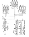
- FIG. 1 there is shown diagrammatically means for use on a consumer's premises for controlling the load on an alternating electrical power supply to be within a predetermined maximum demand level.
- the incoming mains supply is illustrated as a single-phase supply on leads 10, 11 of which lead 10 is the live line and 11 is neutral.
- leads 10, 11 the live line
- 11 is neutral.
- loads 12, 13 and 14 are illustrated. In general a consumer however may have many more loads than this. These loads are energised by two wire supply circuits 15, 16; 17, 18 and 19, 20 respectively.
- the overall demand by the consumer is monitored by means of a current transformer 30 on the lead 10 giving an output signal which is fed to an analogue-to-digital converter 31 in a digital data processing unit 32, conveniently a microprocessor.
- the digital output from the analogue-to-digital converter 31 is compared with a predetermined magnitude set in a memory 33. If the demand, i.e. the signal corresponding to the current in line 10, exceeds the predetermined amount, the unit 32, via a lead 34, sends an operating signal to a solid state switching device, e.g. a triac 35, in the lead 10 to effect a brief interruption of the supply current.
- a solid state switching device e.g. a triac 35
- This interruption is controlled by means of a clock 36 synchronised with the mains voltage waveform obtained from a voltage transformer 37 so that the interruption starts immediately before a zero crossing of the voltage waveform.
- the duration of the interruption in the preferred embodiment, is controlled in accordance with the magnitude of the maximum demand.
- the interruption has a total duration not exceeding about 20 or 30 0 of phase angle, that is to say between 1.0 and 1.7 m.secs for a 50 Hz supply and slightly ' less for a 60 Hz supply. This interruption thus constitutes a signalling waveform.
- the clock 36 controls the cyclic operation of the system and the comparison of the digitised value representing the demand with the preset stored value representing the predetermined maximum demand is, in this particular embodiment, effected once every 71 ⁇ 2 seconds, that is to say every 375 cycles for a 50 Hz supply. It is possible to sample the current much more frequently than this and, by digital data processing in the unit 32, to determine an averaged demand over this period, thereby eliminating the effects of any transients.
- the comparison is made and the signal is sent out at the end of the 7.5 second period. A signal is transmitted only if the measured demand is above the comparison level.
- the unit 40 serves to detect the signals on the waveform and to give appropriate control to the supply to the load.
- the unit 40 includes a solid state switch 41, e.g. a triac, a current transformer 42 responsive to the current in the supply lead 15 to the load and a data processing unit 43 consisting essentially of a small microprocessor.
- This.data processing unit includes a detector 44 detecting the short duration interruption signal effected by the switch 35.
- a counter 45 which is incremented by each successive detected signal. When the count exceeds a predetermined number in a memory in the data processing unit 43, the counter 45 operates, the switch 41 to interrupt the supply to the load 12.
- the switch 41 may be bypassed by a lead, shown in dashed lines at 46 which ensures that power is fed to part of the load even when the switch 41 is opened.
- the lead 46 may for example serve to provide lighting for a refrigerator or freezer or to provide power for a fan in an air-conditioning unit whereas the switch 41 interrupts the supply to the main power consuming parts of the load for example heating and cooling means in an air-conditioning unit.
- the supply remains interrupted until the counter is decremented, in a manner to be described hereinafter, so that the count is taken below the aforementioned predetermined number.
- the different units 40 will have different numbers, the lowest number being associated with the load of lowest priority and the successive further numbers with the loads of more important priority.
- the unit 32 operates the switch 35 to send out a signal consisting of a brief interruption of an alternating current waveform.
- the unit 32 operates the switch 35 to send out a signal consisting of a brief interruption of an alternating current waveform.
- all the units 40 will start their counters 45.
- each counter will, on the first signal count one.
- the count is compared with the preset parameters.
- the unit 40 associated with the load of lowest priority would switch off this load on receipt of this first signal. None of the other loads would be switched off. 71 ⁇ 2 seconds later, if the load is still over the maximum demand, the switch 35 will be operated again to send a further signal. All the counters 45 will detect this signal and will increment by a further unit step and hence the unit 40 of the next higher priority will cause associated loads to be switched off.
- the signal effected by the switch 35 is an interruption of the duration dependent on the measured current.
- the units 40 are arranged so that, if the signal indicates that the total load is below the maximum by a small amount (e.g.
- the switch 35 is operated to send. a signal but this signal is detected by the aforementioned detectors 44 in the various units and, because it is of a duration corresponding to a load below the maximum, the units 40 leave their counters unchanged. If the total load sensed by the current transformer 30 is below the predetermined maximum demand by an appropriate amount, e.g. 3 kW or 6 kW, the unit 32 does not send any signal. The absence of a signal at each of the units 40 causes the counters 45 to be decremented. This decrementing is thus effected under clock control, if no signal is received after 71 ⁇ 2 seconds from the previous signal.
- Decrementing of the counters 45 will, in general, cause one of the loads to be restored because the count for the unit 40 associated with that load is now below the priority number of the load. It will be readily apparent that the units 40 may be arranged to switch on any load if the measured demand is less than the predetermined maximum demand by a particular amount determined by the expected load of that appliance. For this purpose in the various units, the pulse length will be measured in order to obtain information about the magnitude of the sensed demand.
- the count will be incremented and decremented as appropriate.
- the units will also determine the current level for the whole of the maximum demand circuit and will determine the action to be taken. If the count corresponds to the priority of that unit and if the current is over the predetermined maximum, the unit will remain switched off. If the current is just under the predetermined maximum, the unit will remain switched off. If the current is under the maximum by the appropriate amount, typically 3 kW or 6 kW (the amount chosen in accordance with the appliance load) then the counter for this unit (and the counters for all the other units) will be decremented and the load will be switched on.
- the counter will be incremented; the associated load will remain switched on unless this increment takes the count up to the priority number for the unit. If the current is under the maximum, the load will remain switched on. The counter will remain unchanged if the current is just under the maximum but will be decremented if the current is under the maximum demand by more than the aforementioned predetermined amount.
- the units 40 can be made quite small. Conveniently such a unit may be incorporated in a plug top of a plug for connecting an individual load to a power supply socket.
- the unit 32 may include a counter, similar to the counters 45,which is incremented and decremented like the counters 45 but which serves to switch off the supply when the 8 counts have accumulated. It would be necessary then to provide reset means but their nature will depend on the circumstances. It would be possible for example to provide for periodic short duration restoration of the supply and testing of the magnitude of the demand or to provide for manual reset or to provide for automatic restoration after a predetermined period, e.g. 15 or 30 minutes.
- the current transformer3O, switch 35 and data processing unit 32 may form part of a metering and load management control system such as is described in co-pending European Patent Applications Nos. 80300421.7 and 8 0 3 0 0422.5.
- the control arrangement illustrated in Figure 1 enables a consumer to effect automatic switching off, and subsequent switching on again, of individual loads to keep his demand within a predetermined level.
- the various individual loads may be connected for example on a ring main but still be separately controlled in accordance with the overall demand.
- the control units 40 are associated with the various loads and conveniently are located on or near their associated loads. In some cases however, for example where the individual loads are separately fused with the fuses grouped in a fuse box, it may be more convenient to group the units 40 for example at the fuse box.
- This control may be effected by the clock in the unit 40. If supply is restored to a load, it may be desired to prevent interruption of supply to that load for a predetermined period, e.g. one hour. This may also be effected by the clock which is arranged to inhibit switching for the required period.
- Figure 2 there is illustrated schematically an arrangement enabling a utility to switch off individual loads on a consumer's premises, the' individual loads being selected in accordance with a priority which is predetermined.
- the arrangement like that of Figure 1, does not require separate control leads to the individual appliances.
- FIG. 2 there is shown diagrammatically a utility with electric power generating means 50 providing power on a supply circuit 51 (shown diagrammatically as a two-wire circuit) feeding a number of consumers of which three are shown respectively at 52, 53 and 54.
- the utility has means 55 for signalling by modifying the waveform of the supplied power.
- These means 55 might be located near the generator 50 but may be at any other convenient location between the generator and the consumers whose appliances are to be controlled by the signalling means 55.
- the means 55 consists essentially of signalling means controlled by a clock 56 synchronised with the main supply waveform, which clock controls means 57 operative to effect signalling by short duration modification of the waveform.
- This modification conveniently is an interruption starting just before the waveform passes through the zero potential level and ending just after . that point.
- the signalling is initiated automatically and provides a control for effecting, in a manner to be described later, interruption of the supply to selected loads on a consumer's premises for a predetermined time period.
- Each of the consumers has a plurality of loads of which three are shown at 60, 61, 62.
- Each load has a priority interrupt device 63 and one such device 63 is illustrated in further detail in Figure 3.
- This device 63 includes a solid state switch 70, typically a triac, for interrupting the power supply which is fed to the load via a supply conductor 71.
- a solid state switch 70 typically a triac
- the device 63 moreover contains a detector 72 responsive to the signalling waveform produced by the aforementioned unit 55 this waveform being picked up by a current monitoring device 73 e.g. a resistor or current transformer coupled to the supply lead 71.
- the detected signal from the detector 72 is applied to a counter 74.
- the unit 63 furthermore includes a clock 75, the function of which clock will be explained later.
- the count in the counter 74 is compared in a comparator 76 with a reference number in a store 77, .which reference number is representative of an allocated priority for the associated load 60.
- Appliances of the lowest priority conveniently are provided with devices 63 having unity set in the reference store 77 so that the associated load is switched off as soon as a signal on the supply lead is detected. The appliances would then remain switched off for the predetermined time. Appliances of next higher priority would have a higher reference number, for example 2, put in the store so that they would only be switched off on receipt of two detected signals.
- any individual appliance or load part of the load might be fed by a separate lead 78 ( Figure 3) which bypasses the switch 70 so that, for example safety lights may be left in operation.
- the heating or cooling load could be controlled by the switch 70 whilst leaving the fans still in operation.
- Any load which is switched off would be automatically switched on again after the aforementioned predetermined time. Such loads however could be removed again by a further signal on the supply lines from the signalling means 55.
- the switching on of the loads is conveniently effected by utilising the clock 75 to reset the counter 74 to zero ao that the counter is then ready to respond to further detected signals.
- each appliance can have its separate unit 63. Physically this is a very small unit which could for example be incorporated in a special plug for connecting the load to a supply socket.
- Figures 2 and 3 providing for utility control, may be combined with consumer-controlled arrangement of Figure 1. Many component parts of the individual load control units are similar and could be common to a combined system. If the count decrement is to be made in the manner described with reference to Figure 1, then distinctive signals, with separate counters, may be employed for utility control and consumer control.
Abstract
Description
- This invention relates to methods of and apparatus for controlling loads on an electrical power supply.
- It is common practice for electric power to be supplied to consumers under a maximum demand tariff. In order to avoid the need for consumers physically checking and disconnecting loads in order to remain within an agreed maximum demand, it is possible, as is described in our European Patent Application No. 80300422.5 to provide means for automatically. disconnecting a load circuit if the maximum demand is exceeded..For many consumers, particularly domestic consumers, it would be preferable to disconnect individual loads rather than to disconnect a complete circuit by switching means located at or near the position where the maximum demand can be monitored.
- Techniques are known for the transmission of data between a utility and a consumer's premises by distorting the waveform of the supply at one point in the system and detecting the distorted waveform at a remote point; see for example U.K.Patent Specifications Nos.1153908, 1168073 and 1341025.
- It is an object of the present invention to provide a method and means enabling individual load circuits to be disconnected in a predetermined priority order yet which avoids the necessity of separate control circuits to each individual load.
- As will be apparent from the following description such control of individual loads may be desired by a consumer in order to keep within a predetermined maximum overall demand. It may also be desirable however to enable a utility to effect load shedding by disconnection of individual loads in accordance with a predetermined priority instead of having to disconnect supply circuits with the resultant complete interruption of all the supply to some consumers.
- It is convenient to consider in the first place the application of the invention to an alternating supply although, as explained later, the invention may be used with a direct voltage supply.
- According to one aspect of the present invention, a method of controlling loads on an alternating electrical power supply comprises the steps of modifying the alternating waveform of the supply to provide detectable controls signals of a plurality of distinguishably different forms, and, at each individual load to be controlled, detecting and selecting received signals of one of the distinguishably different forms and controlling the supply in accordance with the detected and selected signal.
- With this method, control signals can be signalled over the supply network but each individual load will only respond to a specific distinguishable signal. There is thus no need for any separate signalling system. The distinguishable signals might, for example, call for differing levels of maximum demand or load. At the consumer's premises, individual appliances would have means for detecting and distinguishing between different signals.
- Each of said distinguishably different signals may comprise one or a sequence of similar waveform modifications which are distinguishable by the number of waveform modifications in the sequence, and, at the individual load to be controlled, the signals are distinguished by counting the number of waveform modifications received.
- Particularly if the control is to be by the utility, it is convenient to switch each individual load off for a predetermined period (e.g. 15 or 30 minutes) when the count at that load reaches a predetermined number. The means for detecting and selecting the appropriate signal may be reset during or at the end of said predetermined period.
- There are a number of advantages in using a sequence of signals with a counting technique in that the count number can be in reverse priority order, i.e. the smallest count is for the load to be switched off first. It will be immediately apparent that broadcast transmission of a sequence of some specific number will result in all appliances having means.responsive to that number or to a lower number being switched off. For some loads, frequent switching on and off may be undesirable. In this case, provision may be made, when a load is switched off, for it to remain off for a predetermined period, e.g. 15 minutes. Provision may be made to ensure that a load, after switching on, is not switched off until after a predetermined period.
- According to another aspect of the present invention a method of controlling individual loads on an alternating electrical power supply comprises the steps of monitoring the overall demand, modifying the alternating waveform to provide a signal representative of the overall energy supply when that exceeds a predetermined limit, and, at each appliance to be controlled or associated with the individual supply circuit thereto, detecting said signal, incrementing the count on a counter on detection of said signal, decrementing the count on the counter in the absence of a further signal after a predetermined time, and switching off the individual load, or a part thereof, when the count in the counter exceeds a predetermined value.
- It will be seen that this method of control enables an individual consumer to pre-program his separate loads, e.g. individual appliances,in a predetermined priority order for the purpose of keeping his overall demand within a predetermined limit.
- It will be immediately apparent that, by arranging for the various appliances to be switched off at different count numbers, when said predetermined limit is exceeded, the first appliance (that is to say the appliance of lowest priority) can be switched off on receipt of the first signal. If this does not reduce the demand below the required level, the means sensing the total demand will send out a further signal. The counters in the various appliances will then be incremented a second time and the appliance of the second lowest priority will be switched off. Any number of appliances may be controlled in this way by the transmission of successive signals. In general separate individual loads would be allotted different priority numbers although this is not essential for operation of the system. Typically the cycle time for the signals might be of the order of 7.5 sec. When the load is below the maximum demand, the counts would be decremented and thus the various appliances would be brought back into operation in the appropriate priority order.
- In order to prevent frequent switching on and off of one appliance with the switching on making the demand above the predetermined level and the switching off reducing it below the predetermined level, it is preferred that the decrementing of the counter should occur only when the overall demand is some predetermined value (which would depend on the loads taken by individual appliances but which might typically be of the order of 3 kW or 6 kW) below said predetermined limit. For this purpose, it is preferred that said signal should be representative of the instantaneous energy consumption and that, at or associated with each individual load,this signal is detected and that the counter is decremented only when the instantaneous energy consumption is less than the predetermined maximum limit by said predetermined value. The signal, for this purpose, conveniently consists of an interruption in the waveform of a duration substantially less than a cycle of the alternating power supply, the duration being a measure of the magnitude information to be transmitted, i.e. the rate of energy consumption. Conveniently this is achieved by switching off the supply, using a solid state switch, immediately before the zero crossing of the voltage waveform (or current waveform) and switching on again a short time later, the duration of the interruption being small compared with the time duration of a cycle at the supply frequency. The maximum duration of the interruption might be of the order of 20 or 300 of phase angle, that is to say 1.0 to 1.7 ms for a 50 Hz supply and slightly shorter for a 60 Hz supply.
- It is convenient to measure energy consumption by a current measurement, on the assumption that the voltage will remain constant. In this case the signalling would be used to give a measure of the total current.
- At each unit, if the count on the counter corresponds to the priority of that unit the unit will be switched.off. It will remain switched off until the total current demand by the consumer is less than the maximum by an amount more than the appliance load; the counter will be decremented then and the appliance switched on.
- The invention also includes within its scope apparatus for controlling loads on one alternating electrical power supply comprising means, at each individual load to be controlled, for distinguishing one out of a plurality of different signals broadcast over the supply network as distinguishable modifications of the supply waveform and interrupting the supply to the load when a selected signal is received.
- According to another aspect of the invention, apparatus for controlling loads on an alternating electrical power supply comprises means, at each individual load to be controlled, for detecting and counting the number of signals received as detectable modifications of the supply waveform and means controlling the supply to the load in accordance with the magnitude of the count.
- The means controlling the supply to the load may comprise means comparing the counted number of received signals with a predetermined number and operative to actuate switching means, conveniently a solid state switch, to switch off the supply to the load when the counted number equals said predetermined number.
- The means controlling the supply to the load may be operative to interrupt the supply to the load for a predetermined period and to reset the counting means during or at the end of said predetermined period.
- Each of said signals preferably comprises a short duration interruption of the alternating current waveform, the duration being small compared with the time duration of one cycle at the supply frequency. Thus said means for detecting the signals in this case comprises means for detecting such short interruptions of the supply waveform. The invention furthermore includes an electrical power supply system comprising means for modifying the alternating waveform of the supply to provide one or more detectable control signals in combination with apparatus as described above for controlling individual loads in response to such signals.
- The invention furthermore includes within its scope apparatus for use by a consumer for controlling individual loads on an alternating electrical power supply comprising means for monitoring the overall demand by the consumer, means for modifying the alternating waveform to provide a signal representative of the overall energy supply when that exceeds a predetermined limit, and, at each load to be controlled or associated with the individual supply circuit thereto, data processing means including means for detecting said signal, a counter, means operative to increment the count on said counter when the associated load is taking current and means operative to decrement the count on the counter in the absence of a further signal after a predetermined time, and switch means operative to switch off the individual load, or a part thereof, when the count in the counter exceeds a predetermined value. As previously explained, different loads of a consumer may be arranged to be switched off at different count numbers.
- Furthermore, the invention includes apparatus for use by a consumer for controlling loads on an alternating current power supply to maintain the overall demand by the consumer at or below a predetermined maximum demand comprising means for sensing the overall demand and for determining when said maximum demand is exceeded, means for applying a signal to the various loads by modifying the waveform of the supply when the predetermined maximum demand is exceeded and, associated with or at each individual load to be controlled, means for detecting said signals, a counter with circuit means for incrementing the count each time a signal is received and for decrementing the count in the absence of a signal a predetermined time after the previous signal, switch means operative to interrupt the power supply to the individual load, or part thereof, when the count in the associated counter exceeds a predetermined magnitude, which predetermined magnitudes are different for at least some of the different individual loads and means for closing the switch to restore the supply to said load when the count is below the predetermined number for that load.
- The switch means at each controllable individual load may comprise a solid state switch. The counting and switch control may be effected by a simple microprocessor.
- The apparatus at a consumer's premises may therefore be small and conveniently, for each item of equipment to be controlled, the necessary apparatus may be arranged in the plug of a plug and socket unit for the power supply to the equipment.
- The means for modifying the supply waveform to provide a signal may comprise a solid state switching device to effect an interruption of the supply for a period small compared with the time duration of a cycle of the alternating supply logic means, conveniently embodied in a microprocessor, for controlling the solid state switching device in accordance with the 'measured demand. It is convenient to utilise the current consumption as a measure of the demand and for this purpose there may be provided a current transformer giving an output signal representative of the total demand current, analogue-to-digital conversion means to convert the current into a digital signal and said logic means may be arranged to compare this with a preset maximum demand magnitude and to operate the switching means in accordance with said comparison.
- In some circumstances, it may be desired to provide control by the supply utility of individual loads as well as control by the consumer to limit his maximum demand. For this purpose, the supply utility may have means for signalling by waveform modification and the units associated with the individual loads may be arranged to detect such waveform modifications and to effect the necessary switching using a different waveform modification from that employed by the consumer. The unit can be provided with means for detecting such a signal and for effecting switch operation for a predetermined period, for example 20 minutes, after which the load will be automatically restored. A second set of appliances could be switched off by transmitting a second message for switching off units programmed to detect two successive messages within a predetermined time interval. Similarly further appliances could be switched off with successive further messages. It will be seen that such an arrangement enables a utility to effect load shedding by cutting out the lowest priority loads which loads may be selected by the consumer.
- The switching, whether controlled by the utility or the consumer, since it is for individual appliances, can be arranged to leave lights on in any essential equipment. With air-conditioning equipment for example the fans may be left running but heating or cooling plant switched o.ff. Freezers and refrigerators may be switched off but with any necessary lights left operating.
- With control by the utility, such an arrangement permits of the lowest priority appliances, for example water heating, to be switched off by the utility with load shedding spread evenly amongst all consumers. It thus gives the utility control over a much bigger proportion of this load and ensures that low priority loads are shed most frequently and the highest most infrequently.
- The invention is applicable more generally to any type of power supply, whether alternating or direct voltage. According to another aspect of the invention, therefore, a method of controlling loads on an electrical power supply comprises the steps of-modifying the voltage by short duration pulse interruptions to provide detectable control signals of a plurality of distinguishably different forms and at each individual load to be controlled, detecting and,selecting received signals of one of the distinguishably different forms and controlling that load in accordance with the detected and selected signal. The distinguishable signals comprise distinguishably different numbers of places within a predetermined time period.
- The invention furthermore includes within its scope, apparatus for controlling loads on a electrical power supply comprising the steps of modifying the voltage by short duration pulse interruptions to provide detectable control signals of a plurality of distinguishably different forms and at each individual load to be controlled, detecting and selecting received signals of one of the distinguishably different forms and controlling that load in accordance with the detected and selected signal.
- In the following description, reference will be made to the accompanying drawings in which:- .
- Figure 1 is a block diagram illustrating one embodiment of the invention for the control of electrical power consumption by a consumer to limit the maximum demand;
- Figure 2 is a block diagram of another embodiment of the invention to illustrate means for effecting control by the utility; and
- Figure 3 is a diagram illustrating in further detail part of the apparatus of Figure 2.
- Referring to Figure 1 there is shown diagrammatically means for use on a consumer's premises for controlling the load on an alternating electrical power supply to be within a predetermined maximum demand level. In this diagram the incoming mains supply is illustrated as a single-phase supply on leads 10, 11 of which lead 10 is the live line and 11 is neutral. For simplicity in the description only three
individual loads wire supply circuits 15, 16; 17, 18 and 19, 20 respectively. - The overall demand by the consumer is monitored by means of a
current transformer 30 on the lead 10 giving an output signal which is fed to an analogue-to-digital converter 31 in a digitaldata processing unit 32, conveniently a microprocessor. The digital output from the analogue-to-digital converter 31 is compared with a predetermined magnitude set in amemory 33. If the demand, i.e. the signal corresponding to the current in line 10, exceeds the predetermined amount, theunit 32, via a lead 34, sends an operating signal to a solid state switching device, e.g. atriac 35, in the lead 10 to effect a brief interruption of the supply current. This interruption is controlled by means of a clock 36 synchronised with the mains voltage waveform obtained from a voltage transformer 37 so that the interruption starts immediately before a zero crossing of the voltage waveform. The duration of the interruption, in the preferred embodiment, is controlled in accordance with the magnitude of the maximum demand. The interruption has a total duration not exceeding about 20 or 300 of phase angle, that is to say between 1.0 and 1.7 m.secs for a 50 Hz supply and slightly ' less for a 60 Hz supply. This interruption thus constitutes a signalling waveform. The clock 36 controls the cyclic operation of the system and the comparison of the digitised value representing the demand with the preset stored value representing the predetermined maximum demand is, in this particular embodiment, effected once every 7½ seconds, that is to say every 375 cycles for a 50 Hz supply. It is possible to sample the current much more frequently than this and, by digital data processing in theunit 32, to determine an averaged demand over this period, thereby eliminating the effects of any transients. The comparison is made and the signal is sent out at the end of the 7.5 second period. A signal is transmitted only if the measured demand is above the comparison level. - At each load, there is
unit 40, referred to hereinafter as the priority interrupt device, which serves to detect the signals on the waveform and to give appropriate control to the supply to the load. As is shown for theload 12, theunit 40 includes asolid state switch 41, e.g. a triac, a current transformer 42 responsive to the current in thesupply lead 15 to the load and adata processing unit 43 consisting essentially of a small microprocessor. This.data processing unit includes adetector 44 detecting the short duration interruption signal effected by theswitch 35. There is also acounter 45 which is incremented by each successive detected signal. When the count exceeds a predetermined number in a memory in thedata processing unit 43, thecounter 45 operates, theswitch 41 to interrupt the supply to theload 12. In some circumstances, theswitch 41 may be bypassed by a lead, shown in dashed lines at 46 which ensures that power is fed to part of the load even when theswitch 41 is opened. - The
lead 46 may for example serve to provide lighting for a refrigerator or freezer or to provide power for a fan in an air-conditioning unit whereas theswitch 41 interrupts the supply to the main power consuming parts of the load for example heating and cooling means in an air-conditioning unit. The supply remains interrupted until the counter is decremented, in a manner to be described hereinafter, so that the count is taken below the aforementioned predetermined number. Thedifferent units 40 will have different numbers, the lowest number being associated with the load of lowest priority and the successive further numbers with the loads of more important priority. - The operation of the above-described system is as follows: when the demand detected by the current transformer 30 (and determined after averaging over a period of at least a few cycles and possibly up to 7.5 seconds) exceeds the predetermined level, the
unit 32 operates theswitch 35 to send out a signal consisting of a brief interruption of an alternating current waveform. On the first such signal, all theunits 40 will start theircounters 45. Thus each counter will, on the first signal count one. The count is compared with the preset parameters. Theunit 40 associated with the load of lowest priority would switch off this load on receipt of this first signal. None of the other loads would be switched off. 7½ seconds later, if the load is still over the maximum demand, theswitch 35 will be operated again to send a further signal. All thecounters 45 will detect this signal and will increment by a further unit step and hence theunit 40 of the next higher priority will cause associated loads to be switched off. - In the simplest arrangement, if the total load sensed by the
current transformer 30 is below the maximum, no signal would be sent. If no signal is received after 7% seconds, aclock 47 in each of theunits 40 would decrement the counters by one unit. If the count was two and was decremented to one, then the load associated with the unit of second lowest priority would then be switched on. It is desirable however to avoid repetitive switching on and off of one load if the demand is caused to rise and fall below the predetermined level by switching of a single load. In the embodiment described, the signal effected by theswitch 35 is an interruption of the duration dependent on the measured current. Theunits 40 are arranged so that, if the signal indicates that the total load is below the maximum by a small amount (e.g. less than 3 kW or less than 6 kW depending on the magnitude of individual loads), theswitch 35 is operated to send. a signal but this signal is detected by theaforementioned detectors 44 in the various units and, because it is of a duration corresponding to a load below the maximum, theunits 40 leave their counters unchanged. If the total load sensed by thecurrent transformer 30 is below the predetermined maximum demand by an appropriate amount, e.g. 3 kW or 6 kW, theunit 32 does not send any signal. The absence of a signal at each of theunits 40 causes thecounters 45 to be decremented. This decrementing is thus effected under clock control, if no signal is received after 7½ seconds from the previous signal. Decrementing of thecounters 45 will, in general, cause one of the loads to be restored because the count for theunit 40 associated with that load is now below the priority number of the load. It will be readily apparent that theunits 40 may be arranged to switch on any load if the measured demand is less than the predetermined maximum demand by a particular amount determined by the expected load of that appliance. For this purpose in the various units, the pulse length will be measured in order to obtain information about the magnitude of the sensed demand. - It will be seen that, in each of the
units 40, the count will be incremented and decremented as appropriate. The units will also determine the current level for the whole of the maximum demand circuit and will determine the action to be taken. If the count corresponds to the priority of that unit and if the current is over the predetermined maximum, the unit will remain switched off. If the current is just under the predetermined maximum, the unit will remain switched off. If the current is under the maximum by the appropriate amount, typically 3 kW or 6 kW (the amount chosen in accordance with the appliance load) then the counter for this unit (and the counters for all the other units) will be decremented and the load will be switched on. If the current for the overall supply is over the maximum, the counter will be incremented; the associated load will remain switched on unless this increment takes the count up to the priority number for the unit. If the current is under the maximum, the load will remain switched on. The counter will remain unchanged if the current is just under the maximum but will be decremented if the current is under the maximum demand by more than the aforementioned predetermined amount. - Physically the
units 40 can be made quite small. Conveniently such a unit may be incorporated in a plug top of a plug for connecting an individual load to a power supply socket. - In some cases, for example where load-controlling
units 40 are not provided for all the loads, provision may be made for switching off the overall supply, using theswitch 35 if more than a predetermined number of counts (e.g. 8 counts if there are fewer than 8 controlled loads) are accumulated. For this purpose, theunit 32 may include a counter, similar to thecounters 45,which is incremented and decremented like thecounters 45 but which serves to switch off the supply when the 8 counts have accumulated. It would be necessary then to provide reset means but their nature will depend on the circumstances. It would be possible for example to provide for periodic short duration restoration of the supply and testing of the magnitude of the demand or to provide for manual reset or to provide for automatic restoration after a predetermined period, e.g. 15 or 30 minutes. - The current transformer3O, switch 35 and
data processing unit 32 may form part of a metering and load management control system such as is described in co-pending European Patent Applications Nos. 80300421.7 and 80300422.5. - The control arrangement illustrated in Figure 1 enables a consumer to effect automatic switching off, and subsequent switching on again, of individual loads to keep his demand within a predetermined level.
- This control is effected however without any need for separate control leads to the various units. The various individual loads may be connected for example on a ring main but still be separately controlled in accordance with the overall demand. The
control units 40 are associated with the various loads and conveniently are located on or near their associated loads. In some cases however, for example where the individual loads are separately fused with the fuses grouped in a fuse box, it may be more convenient to group theunits 40 for example at the fuse box. - In some cases it may be preferred to effect the , restoration of supply to an individual load at a predetermined time interval, e.g. 15 minutes, after the supply has been switched off. This control may be effected by the clock in the
unit 40. If supply is restored to a load, it may be desired to prevent interruption of supply to that load for a predetermined period, e.g. one hour. This may also be effected by the clock which is arranged to inhibit switching for the required period. - In Figure 2 there is illustrated schematically an arrangement enabling a utility to switch off individual loads on a consumer's premises, the' individual loads being selected in accordance with a priority which is predetermined. The arrangement, like that of Figure 1, does not require separate control leads to the individual appliances.
- Referring to Figure 2 there is shown diagrammatically a utility with electric power generating means 50 providing power on a supply circuit 51 (shown diagrammatically as a two-wire circuit) feeding a number of consumers of which three are shown respectively at 52, 53 and 54. The utility has means 55 for signalling by modifying the waveform of the supplied power. These means 55 might be located near the generator 50 but may be at any other convenient location between the generator and the consumers whose appliances are to be controlled by the signalling means 55.
- The means 55 consists essentially of signalling means controlled by a
clock 56 synchronised with the main supply waveform, which clock controls means 57 operative to effect signalling by short duration modification of the waveform. This modification conveniently is an interruption starting just before the waveform passes through the zero potential level and ending just after . that point. The signalling is initiated automatically and provides a control for effecting, in a manner to be described later, interruption of the supply to selected loads on a consumer's premises for a predetermined time period. - Each of the consumers has a plurality of loads of which three are shown at 60, 61, 62. Each load has a priority interrupt
device 63 and onesuch device 63 is illustrated in further detail in Figure 3. - Referring to Figure 3, there is shown one of the
loads 60 with the associated priority interruptdevice 63. Thisdevice 63 includes asolid state switch 70, typically a triac, for interrupting the power supply which is fed to the load via a supply conductor 71. - The
device 63 moreover contains adetector 72 responsive to the signalling waveform produced by theaforementioned unit 55 this waveform being picked up by a current monitoring device 73 e.g. a resistor or current transformer coupled to the supply lead 71. The detected signal from thedetector 72 is applied to acounter 74. Theunit 63 furthermore includes a clock 75, the function of which clock will be explained later. The count in thecounter 74 is compared in acomparator 76 with a reference number in astore 77, .which reference number is representative of an allocated priority for the associatedload 60. When the count reaches the,reference number in thestore 77, a control signal is produced by thecomparator 76 which operates theaforementioned switch 70 to switch off the supply to theload 60 for a predetermined time for example 15 or 30 minutes, this time being controlled by the clock 75 which is triggered by the control signal and which is operative to restore the supply after the predetermined time. - Appliances of the lowest priority conveniently are provided with
devices 63 having unity set in thereference store 77 so that the associated load is switched off as soon as a signal on the supply lead is detected. The appliances would then remain switched off for the predetermined time. Appliances of next higher priority would have a higher reference number, for example 2, put in the store so that they would only be switched off on receipt of two detected signals. - It will be immediately apparent that, by such an arrangement, some or all of the appliances on a consumer's premises may be directly controlled by the utility to be switched off in the event of excessive demand on the power supply. The devices would be switched with those of lowest priority first. Transmission of a single signal from the signalling means 55 can thus effect load shedding over a whole supply network with only the lowest priority loads being disconnected. Typically, if this did not produce sufficient reduction in demand, a second signal would then be transmitted so as to switch off devices of the next higher priority and so on. A utility can thus, in an emergency when load shedding is necessary, effect a controlled reduction in demand without cutting off completely the supply to any consumer. Apparatus which has to be kept in operation, for example for safety reasons, can be left connected to the supply. In any individual appliance or load, part of the load might be fed by a separate lead 78 (Figure 3) which bypasses the
switch 70 so that, for example safety lights may be left in operation. In air-conditioning equipment, the heating or cooling load could be controlled by theswitch 70 whilst leaving the fans still in operation. - Any load which is switched off would be automatically switched on again after the aforementioned predetermined time. Such loads however could be removed again by a further signal on the supply lines from the signalling means 55. The switching on of the loads is conveniently effected by utilising the clock 75 to reset the
counter 74 to zero ao that the counter is then ready to respond to further detected signals. - It will be seen that, from the point of view of the consumer, when load-shedding is required, he would lose only certain loads and can keep a supply to the more essential loads. From the point of view of the utility, such an arrangement enables any load-shedding to be spread evenly over all or substantially all consumers.
- A much bigger controllable load is available than with conventional techniques of complete disconnection of specific circuits. The utility has control over a large percentage of its domestic load whilst ensuring always that low priority loads are shed the most frequently and the highest most infrequently. All consumers can be treated equally at all times.
- It will be noted that there is no need to have any special wiring as each appliance can have its
separate unit 63. Physically this is a very small unit which could for example be incorporated in a special plug for connecting the load to a supply socket. - The arrangement of Figures 2 and 3, providing for utility control, may be combined with consumer-controlled arrangement of Figure 1. Many component parts of the individual load control units are similar and could be common to a combined system. If the count decrement is to be made in the manner described with reference to Figure 1, then distinctive signals, with separate counters, may be employed for utility control and consumer control.
Claims (24)
Priority Applications (1)
| Application Number | Priority Date | Filing Date | Title |
|---|---|---|---|
| AT81303720T ATE10406T1 (en) | 1980-09-01 | 1981-08-14 | METHOD AND DEVICE FOR LOAD CONTROL OF AN ELECTRICAL POWER SUPPLY. |
Applications Claiming Priority (2)
| Application Number | Priority Date | Filing Date | Title |
|---|---|---|---|
| GB8028189 | 1980-09-01 | ||
| GB8028189A GB2083301B (en) | 1980-09-01 | 1980-09-01 | Method of and apparatus for controlling loads on an electrical power supply |
Publications (2)
| Publication Number | Publication Date |
|---|---|
| EP0047089A1 true EP0047089A1 (en) | 1982-03-10 |
| EP0047089B1 EP0047089B1 (en) | 1984-11-21 |
Family
ID=10515770
Family Applications (1)
| Application Number | Title | Priority Date | Filing Date |
|---|---|---|---|
| EP81303720A Expired EP0047089B1 (en) | 1980-09-01 | 1981-08-14 | Method of and apparatus for controlling loads on an electrical power supply |
Country Status (9)
| Country | Link |
|---|---|
| US (1) | US4471232A (en) |
| EP (1) | EP0047089B1 (en) |
| JP (1) | JPS5775322A (en) |
| AT (1) | ATE10406T1 (en) |
| AU (1) | AU553281B2 (en) |
| CA (1) | CA1179404A (en) |
| DE (1) | DE3167317D1 (en) |
| GB (1) | GB2083301B (en) |
| NZ (1) | NZ198094A (en) |
Cited By (18)
| Publication number | Priority date | Publication date | Assignee | Title |
|---|---|---|---|---|
| GB2151115A (en) * | 1983-11-21 | 1985-07-10 | Concord Controls Limited | Control circuit for a fluorescent tube |
| FR2592999A1 (en) * | 1986-01-15 | 1987-07-17 | Merlin Gerin | Load-shedding relay, in particular with peak day override |
| FR2593001A1 (en) * | 1986-01-15 | 1987-07-17 | Merlin Gerin | Load-shedding relay |
| EP0233127A1 (en) * | 1986-01-15 | 1987-08-19 | Merlin Gerin | Circuit-breaking relay |
| EP0237444A1 (en) * | 1986-01-15 | 1987-09-16 | Merlin Gerin | Circuit breaking relays, especially with "peak period disconnection" |
| DE3612894A1 (en) * | 1986-04-17 | 1987-10-22 | Kernkraftwerke Gundremmingen | DEVICE FOR IDENTIFYING AN UNLOCKED ELECTRICAL EQUIPMENT |
| EP0456395A2 (en) * | 1990-05-08 | 1991-11-13 | International Business Machines Corporation | System and method for monitoring electronic data processing equipment |
| FR2710801A1 (en) * | 1993-09-30 | 1995-04-07 | Bosch Gmbh Robert | Mounting arrangement for transmitting information on a two-wire power line. |
| WO1996001520A1 (en) * | 1994-07-04 | 1996-01-18 | Vattenfall Ab | Distribution network and method and device for regulating electric current from the network |
| WO2009152534A2 (en) * | 2008-02-15 | 2009-12-17 | Stefan Swanepoel | Electrical demand controller |
| EP2192386A1 (en) | 2008-11-27 | 2010-06-02 | ubitricity Gesellschaft für verteilte Energiesysteme mbH | Counting and measuring point system for measuring and counting electric energy and method |
| US8035341B2 (en) | 2010-07-12 | 2011-10-11 | Better Place GmbH | Staged deployment for electrical charge spots |
| US8118147B2 (en) | 2009-09-11 | 2012-02-21 | Better Place GmbH | Cable dispensing system |
| US8164300B2 (en) | 2008-09-19 | 2012-04-24 | Better Place GmbH | Battery exchange station |
| US8246376B2 (en) | 2009-09-14 | 2012-08-21 | Better Place GmbH | Electrical connector with flexible blade shaped handle |
| DE202012012557U1 (en) | 2011-11-25 | 2013-05-08 | ubitricity Gesellschaft für verteilte Energiesysteme mbH | Counting and measuring point system for the measurement and counting of electrical energy / electricity |
| US8454377B2 (en) | 2008-09-19 | 2013-06-04 | Better Place GmbH | System for electrically connecting batteries to electric vehicles |
| DE202011110435U1 (en) | 2011-11-25 | 2014-01-07 | ubitricity Gesellschaft für verteilte Energiesysteme mbH | Inductive removal and / or feeding device for inductive removal and / or feeding of electrical energy / electricity by electric vehicles |
Families Citing this family (84)
| Publication number | Priority date | Publication date | Assignee | Title |
|---|---|---|---|---|
| US4540890A (en) * | 1982-05-24 | 1985-09-10 | Galber Automazione E | System for selectively addressing electrical control signals from a control unit to a plurality of remote units |
| US4556864A (en) * | 1982-08-26 | 1985-12-03 | Roy Joseph J | Apparatus and method for communicating digital information on AC power lines |
| US4620283A (en) * | 1983-11-29 | 1986-10-28 | Lehigh University | Programmable load controller |
| DE3508403A1 (en) * | 1985-03-08 | 1986-09-11 | Vsesojuznyj naučno-issledovatel'skij i proektno-konstruktorskij ugol'nyj institut (KNIUI), Karaganda | Sparkproof power-supply system for remote-control devices |
| GB2188799A (en) * | 1986-04-04 | 1987-10-07 | Philip Hall Bertenshaw | Control system for electric power distribution |
| FR2600466B1 (en) * | 1986-06-20 | 1994-03-18 | Cahors Manuf Appareillage Electr | POWER ADAPTER FOR ELECTRICAL INSTALLATIONS, ESPECIALLY DOMESTIC, WITH DRIVE CONTROL BY CARRIER CURRENTS |
| GB2194867B (en) * | 1986-09-09 | 1991-05-29 | Mitsubishi Electric Corp | A transmission line control system and method for disconnecting a sub-bus from a main-bus |
| US4847781A (en) * | 1986-09-23 | 1989-07-11 | Associated Data Consoltants | Energy management system |
| US4847782A (en) * | 1986-09-23 | 1989-07-11 | Associated Data Consultants, Inc. | Energy management system with responder unit having an override |
| US4748426A (en) * | 1986-11-07 | 1988-05-31 | Rodime Plc | Active termination circuit for computer interface use |
| DE3701493A1 (en) * | 1987-01-20 | 1988-07-28 | Nixdorf Computer Ag | CIRCUIT ARRANGEMENT FOR DISTRIBUTING ELECTRICAL POWER TO MULTIPLE FUNCTIONAL UNITS |
| US5687139A (en) * | 1987-03-23 | 1997-11-11 | Budney; Stanley M. | Electrical load optimization device |
| GB8707480D0 (en) * | 1987-03-28 | 1987-04-29 | Pulsar Light Of Cambridge Ltd | Electrical switching apparatus |
| DE3715590A1 (en) * | 1987-05-09 | 1988-12-01 | Gewerk Eisenhuette Westfalia | POWER SUPPLY DEVICE FOR ELECTROHYDRAULIC EXTENSION CONTROLS OR OTHER CONTROL SYSTEMS IN MINING AND PITCHING |
| US4823022A (en) * | 1987-05-15 | 1989-04-18 | Lindsey Manufacturing Company | Apparatus and method for sensing power line conditions |
| US4785195A (en) * | 1987-06-01 | 1988-11-15 | University Of Tennessee Research Corporation | Power line communication |
| JPH03503833A (en) * | 1988-02-23 | 1991-08-22 | アルカテル・エヌ・ブイ | electrical load reduction circuit |
| JPH0621656B2 (en) * | 1988-09-28 | 1994-03-23 | 本田技研工業株式会社 | Swash plate type hydraulic system |
| JPH0340724A (en) * | 1988-11-18 | 1991-02-21 | Jan Gerrit Toennies | Load acting method for power system ,and electric meter, indicating device, and switching deviceusedin that method |
| US4970623A (en) * | 1988-12-29 | 1990-11-13 | Hewlett-Packard Company | Peripheral device power activation circuit and method therefor |
| EP0664598A3 (en) * | 1989-02-06 | 1995-09-20 | Boral Johns Perry Industries Pty. Ltd. | Power supply system |
| US5243225A (en) * | 1989-09-18 | 1993-09-07 | 564935 Ontario Limited | Load shedding system |
| US5079437A (en) * | 1990-03-20 | 1992-01-07 | The United States Of America As Represented By The Secretary Of The Army | Multi-voltage power supply |
| DE4023846C2 (en) * | 1990-07-27 | 1998-09-10 | Aeg Hausgeraete Gmbh | Control unit for a washing machine and a tumble dryer |
| JP3219202B2 (en) * | 1991-06-07 | 2001-10-15 | ソニー株式会社 | Electronic devices and equipment |
| US5442335A (en) * | 1992-11-13 | 1995-08-15 | I.D. Tek Inc. | Controller for controlling operation of at least one electrical load operating on an AC supply, and a method thereof |
| AU5603994A (en) * | 1992-11-13 | 1994-06-08 | Group Dekko International | Safety shut-off for modular office panels |
| US5324989A (en) * | 1992-12-17 | 1994-06-28 | Thornton Roger D | Power controller module providing user selectable overload protection |
| US5453697A (en) * | 1993-09-09 | 1995-09-26 | Carma Industries | Technique for calibrating a transformer element |
| US5400009A (en) | 1993-10-07 | 1995-03-21 | Wheelock Inc. | Synchronization circuit for visual/audio alarms |
| GB9406625D0 (en) * | 1994-04-05 | 1994-05-25 | Smiths Industries Plc | Electrical systems and connectors |
| GB2288291B (en) * | 1994-04-05 | 1998-06-10 | Smiths Industries Plc | Electrical systems and connectors |
| DE4444024A1 (en) * | 1994-12-10 | 1996-06-13 | Festo Kg | Control device, in particular for controlling valves |
| GB9503352D0 (en) * | 1995-02-21 | 1995-04-12 | Sinnett Glyn | Remote control system |
| US6906616B1 (en) * | 1995-03-20 | 2005-06-14 | Wheelock, Inc. | Apparatus and method for synchronizing visual/audible alarm units in an alarm system |
| US6194994B1 (en) | 1995-03-20 | 2001-02-27 | Wheelock, Inc. | Apparatus and method for synchronizing visual/audible alarm units in an alarm system |
| US5608375A (en) * | 1995-03-20 | 1997-03-04 | Wheelock Inc. | Synchronized visual/audible alarm system |
| US5866956A (en) * | 1995-06-06 | 1999-02-02 | Dekko Engineering, Inc. | Apparatus for and method of monitoring and controlling a power system |
| US5581132A (en) * | 1995-08-04 | 1996-12-03 | Chadwick; Jon D. | Peak demand limiter and sequencer |
| AUPN547695A0 (en) * | 1995-09-15 | 1995-10-12 | H.P.M. Industries Pty Limited | Electrical control system |
| US5710691A (en) * | 1996-04-26 | 1998-01-20 | Fowler; David C. | Programmable control unit |
| IT1284464B1 (en) * | 1996-07-04 | 1998-05-21 | Bticino Spa | SIGNALING AND CODING SYSTEM FOR THE PILOTING OF ELECTRIC ACTUATORS |
| DE19650381C1 (en) * | 1996-12-05 | 1998-05-28 | Kostal Leopold Gmbh & Co Kg | Circuit arrangement |
| US5747973A (en) * | 1996-12-11 | 1998-05-05 | Shop Vac Corporation | Current regulating switch circuit |
| US5942814A (en) * | 1997-04-28 | 1999-08-24 | Echelon Corporation | Module for controlling current to a load including sensing of the position of a switch |
| US6211627B1 (en) | 1997-07-29 | 2001-04-03 | Michael Callahan | Lighting systems |
| FR2788381B1 (en) * | 1999-01-13 | 2002-11-22 | Fabien Cavic | PROTECTION AND MANAGEMENT DEVICE OF AN ELECTRICAL INSTALLATION, ESPECIALLY DOMESTIC |
| WO2000064027A1 (en) * | 1999-04-16 | 2000-10-26 | Manning Tronics, Inc. | Electrical peak load distributor |
| EP1050974A3 (en) * | 1999-05-03 | 2002-02-06 | DDL Design N.V. | A data communication device |
| GB9927142D0 (en) * | 1999-11-17 | 2000-01-12 | Carver Plc | Electrical control system |
| US6348777B1 (en) | 2000-02-29 | 2002-02-19 | Alaris Medical Systems, Inc. | Power management system |
| US6891478B2 (en) * | 2000-06-09 | 2005-05-10 | Jay Warren Gardner | Methods and apparatus for controlling electric appliances during reduced power conditions |
| GB0015559D0 (en) * | 2000-06-27 | 2000-08-16 | Oxley Dev Co Ltd | Device controller and control arrangement |
| KR100700817B1 (en) * | 2000-09-29 | 2007-03-27 | 마쯔시다덴기산교 가부시키가이샤 | Power supply/demand control system |
| JP2002118961A (en) * | 2000-10-04 | 2002-04-19 | Sanyo Electric Co Ltd | Electric power load management system |
| DE10053750A1 (en) * | 2000-10-30 | 2002-06-06 | Siemens Ag | Method and device for the overload-free control of an actuator |
| MXPA01000550A (en) * | 2001-01-16 | 2002-07-17 | Tomas Ortega Murguia Jose | Electrical power saving system. |
| US6800957B2 (en) * | 2001-02-06 | 2004-10-05 | General Electric Company | Electronic distribution system for 36V automobiles |
| US6828695B1 (en) * | 2001-04-09 | 2004-12-07 | Rick L. Hansen | System, apparatus and method for energy distribution monitoring and control and information transmission |
| EP1447809A1 (en) * | 2003-02-14 | 2004-08-18 | SCHLUMBERGER Systèmes | Card with multiple IC's |
| JP2004272562A (en) * | 2003-03-07 | 2004-09-30 | Orion Denki Kk | Electrical equipment |
| US7177728B2 (en) * | 2003-12-30 | 2007-02-13 | Jay Warren Gardner | System and methods for maintaining power usage within a set allocation |
| US7230522B2 (en) * | 2004-05-06 | 2007-06-12 | Stevens Carlile R | Power line communication device and method |
| US20080191637A1 (en) * | 2004-09-24 | 2008-08-14 | Pettler Peter R | Method and apparatus for controlling electrical lighting installations |
| US8615332B2 (en) * | 2005-06-09 | 2013-12-24 | Whirlpool Corporation | Smart current attenuator for energy conservation in appliances |
| NZ540927A (en) * | 2005-06-22 | 2008-03-28 | Traffic Electronics Ltd | Communication system for inductive power transfer system |
| US8373547B2 (en) * | 2006-05-25 | 2013-02-12 | Nev Electronics Llc | Method and apparatus for using power-line phase-cut signaling to change energy usage |
| EP2149957B1 (en) * | 2008-07-30 | 2017-06-14 | Harman Becker Automotive Systems GmbH | Priority based power distribution arrangement |
| US8874277B2 (en) * | 2009-09-15 | 2014-10-28 | Denis Kouroussis | Smart-grid adaptive power management method and system with power factor optimization and total harmonic distortion reduction |
| US9130400B2 (en) * | 2009-09-24 | 2015-09-08 | Apple Inc. | Multiport power converter with load detection capabilities |
| US8575917B2 (en) * | 2009-09-24 | 2013-11-05 | Apple Inc. | Multirange load detection circuitry |
| JP4924696B2 (en) * | 2009-11-04 | 2012-04-25 | ダイキン工業株式会社 | Wall-mounted indoor unit |
| US20110278921A1 (en) * | 2010-05-11 | 2011-11-17 | Erik Jon Fretheim | Adaptive Power Bus |
| EP2589277B1 (en) | 2010-06-30 | 2018-09-19 | Ergotron, Inc. | Electrical load management system and method |
| US20120017611A1 (en) * | 2010-07-20 | 2012-01-26 | Coffel James A | Load management aware fan control |
| US8682604B2 (en) | 2011-08-03 | 2014-03-25 | General Electric Company | Method and system of phase identification |
| CA2856433C (en) | 2012-06-01 | 2016-08-16 | Bipco-Soft R3 Inc. | Power control device |
| CN105121283B (en) | 2013-02-28 | 2017-12-05 | Bae系统控制有限公司 | Seat power system and method |
| WO2016044719A1 (en) | 2014-09-18 | 2016-03-24 | Ergotron, Inc. | Electrical load management system and method |
| WO2018148835A1 (en) | 2017-02-15 | 2018-08-23 | Simon Jasmin | Power control device |
| DE102017006678A1 (en) * | 2017-07-14 | 2019-01-17 | Drägerwerk AG & Co. KGaA | Cascadable multi-loader and method of operation thereof |
| US10201059B1 (en) | 2017-08-01 | 2019-02-05 | Kleverness Incorporated | Method for analyzing operating parameters for lighting technologies |
| US10123393B1 (en) | 2017-08-01 | 2018-11-06 | Kleverness Incorporated | Power supply for a two-wire smart switch and lighting loads thereof |
| US10201064B1 (en) | 2017-08-01 | 2019-02-05 | Kleverness Incorporated | Power supply for a two-wire smart dimmer and lighting loads thereof |
Citations (5)
| Publication number | Priority date | Publication date | Assignee | Title |
|---|---|---|---|---|
| US3489913A (en) * | 1968-08-02 | 1970-01-13 | Theodore Wildi | Load-control and power-distributing system |
| US3540030A (en) * | 1969-09-29 | 1970-11-10 | Detroit Edison Co | Structure for and method of powerline load remote control |
| FR2295604A1 (en) * | 1974-12-21 | 1976-07-16 | Hartmann & Braun Ag | Maximum load electronic controller - pulse counter cct. switches out as function of time partial loads and overloads |
| GB2008299A (en) * | 1977-11-17 | 1979-05-31 | Consumer Elec Prod | Remote control over power lines |
| WO1980001024A1 (en) * | 1978-11-13 | 1980-05-15 | Medibit As | Process for transferring information and system for carrying out the process |
Family Cites Families (7)
| Publication number | Priority date | Publication date | Assignee | Title |
|---|---|---|---|---|
| JPS5353754A (en) * | 1976-10-27 | 1978-05-16 | Mitsubishi Electric Corp | Power consuption controller |
| JPS53147954A (en) * | 1977-05-31 | 1978-12-23 | Mitsubishi Electric Corp | Power consumption controller |
| JPS5552121A (en) * | 1978-10-13 | 1980-04-16 | Tokyo Electric Power Co Inc:The | Demand control unit |
| GB2043371B (en) * | 1979-02-21 | 1983-05-25 | South Eastern Elec Board | Load shedding |
| US4245319A (en) * | 1979-03-19 | 1981-01-13 | Cyborex Laboratories, Inc. | Energy management method and apparatus utilizing duty cycle reduction synchronized with the zero points of the applied voltage |
| US4264960A (en) * | 1979-07-02 | 1981-04-28 | Sangamo Weston, Inc. | System for controlling power distribution to customer loads |
| NZ195708A (en) * | 1979-12-07 | 1984-04-27 | Gen Electric Co Ltd | Receiver for detection of ac signalling voltage reductions at zero crossings |
-
1980
- 1980-09-01 GB GB8028189A patent/GB2083301B/en not_active Expired
-
1981
- 1981-08-14 DE DE8181303720T patent/DE3167317D1/en not_active Expired
- 1981-08-14 AT AT81303720T patent/ATE10406T1/en not_active IP Right Cessation
- 1981-08-14 EP EP81303720A patent/EP0047089B1/en not_active Expired
- 1981-08-19 NZ NZ198094A patent/NZ198094A/en unknown
- 1981-08-27 US US06/296,928 patent/US4471232A/en not_active Expired - Lifetime
- 1981-08-28 AU AU74729/81A patent/AU553281B2/en not_active Ceased
- 1981-08-31 JP JP13694581A patent/JPS5775322A/en active Granted
- 1981-08-31 CA CA000384866A patent/CA1179404A/en not_active Expired
Patent Citations (5)
| Publication number | Priority date | Publication date | Assignee | Title |
|---|---|---|---|---|
| US3489913A (en) * | 1968-08-02 | 1970-01-13 | Theodore Wildi | Load-control and power-distributing system |
| US3540030A (en) * | 1969-09-29 | 1970-11-10 | Detroit Edison Co | Structure for and method of powerline load remote control |
| FR2295604A1 (en) * | 1974-12-21 | 1976-07-16 | Hartmann & Braun Ag | Maximum load electronic controller - pulse counter cct. switches out as function of time partial loads and overloads |
| GB2008299A (en) * | 1977-11-17 | 1979-05-31 | Consumer Elec Prod | Remote control over power lines |
| WO1980001024A1 (en) * | 1978-11-13 | 1980-05-15 | Medibit As | Process for transferring information and system for carrying out the process |
Cited By (26)
| Publication number | Priority date | Publication date | Assignee | Title |
|---|---|---|---|---|
| GB2151115A (en) * | 1983-11-21 | 1985-07-10 | Concord Controls Limited | Control circuit for a fluorescent tube |
| FR2592999A1 (en) * | 1986-01-15 | 1987-07-17 | Merlin Gerin | Load-shedding relay, in particular with peak day override |
| FR2593001A1 (en) * | 1986-01-15 | 1987-07-17 | Merlin Gerin | Load-shedding relay |
| EP0233127A1 (en) * | 1986-01-15 | 1987-08-19 | Merlin Gerin | Circuit-breaking relay |
| EP0237444A1 (en) * | 1986-01-15 | 1987-09-16 | Merlin Gerin | Circuit breaking relays, especially with "peak period disconnection" |
| DE3612894A1 (en) * | 1986-04-17 | 1987-10-22 | Kernkraftwerke Gundremmingen | DEVICE FOR IDENTIFYING AN UNLOCKED ELECTRICAL EQUIPMENT |
| EP0456395A2 (en) * | 1990-05-08 | 1991-11-13 | International Business Machines Corporation | System and method for monitoring electronic data processing equipment |
| EP0456395A3 (en) * | 1990-05-08 | 1993-09-01 | International Business Machines Corporation | System and method for monitoring electronic data processing equipment |
| FR2710801A1 (en) * | 1993-09-30 | 1995-04-07 | Bosch Gmbh Robert | Mounting arrangement for transmitting information on a two-wire power line. |
| WO1996001520A1 (en) * | 1994-07-04 | 1996-01-18 | Vattenfall Ab | Distribution network and method and device for regulating electric current from the network |
| AU681975B2 (en) * | 1994-07-04 | 1997-09-11 | Vattenfall Ab | Distribution network and method and device for regulating electric current from the network |
| US5903064A (en) * | 1994-07-04 | 1999-05-11 | Vattenfall Ab (Public) | Distribution network and method and device for regulating electric current from the network |
| WO2009152534A2 (en) * | 2008-02-15 | 2009-12-17 | Stefan Swanepoel | Electrical demand controller |
| WO2009152534A3 (en) * | 2008-02-15 | 2010-06-03 | Stefan Swanepoel | Electrical demand controller |
| US8454377B2 (en) | 2008-09-19 | 2013-06-04 | Better Place GmbH | System for electrically connecting batteries to electric vehicles |
| US8164300B2 (en) | 2008-09-19 | 2012-04-24 | Better Place GmbH | Battery exchange station |
| US8517132B2 (en) | 2008-09-19 | 2013-08-27 | Better Place GmbH | Electric vehicle battery system |
| DE202008017797U1 (en) | 2008-11-27 | 2010-07-22 | ubitricity Gesellschaft für verteilte Energiesysteme mbH | Counting and measuring point system for measuring and counting electrical energy |
| EP2192386A1 (en) | 2008-11-27 | 2010-06-02 | ubitricity Gesellschaft für verteilte Energiesysteme mbH | Counting and measuring point system for measuring and counting electric energy and method |
| US8118147B2 (en) | 2009-09-11 | 2012-02-21 | Better Place GmbH | Cable dispensing system |
| US8246376B2 (en) | 2009-09-14 | 2012-08-21 | Better Place GmbH | Electrical connector with flexible blade shaped handle |
| US8035341B2 (en) | 2010-07-12 | 2011-10-11 | Better Place GmbH | Staged deployment for electrical charge spots |
| WO2013076001A1 (en) | 2011-11-25 | 2013-05-30 | ubitricity Gesellschaft für verteilte Energiesysteme mbH | Metering and measuring-point system for measuring and metering electrical power/electricity, and a method |
| EP2597426A1 (en) | 2011-11-25 | 2013-05-29 | ubitricity Gesellschaft für verteilte Energiesysteme mbH | Counting and measuring point system for measuring and counting electrical energy/electricity and method |
| DE202012012557U1 (en) | 2011-11-25 | 2013-05-08 | ubitricity Gesellschaft für verteilte Energiesysteme mbH | Counting and measuring point system for the measurement and counting of electrical energy / electricity |
| DE202011110435U1 (en) | 2011-11-25 | 2014-01-07 | ubitricity Gesellschaft für verteilte Energiesysteme mbH | Inductive removal and / or feeding device for inductive removal and / or feeding of electrical energy / electricity by electric vehicles |
Also Published As
| Publication number | Publication date |
|---|---|
| NZ198094A (en) | 1985-10-11 |
| AU7472981A (en) | 1982-03-11 |
| CA1179404A (en) | 1984-12-11 |
| US4471232A (en) | 1984-09-11 |
| JPS5775322A (en) | 1982-05-11 |
| GB2083301B (en) | 1984-09-26 |
| JPH0254576B2 (en) | 1990-11-22 |
| ATE10406T1 (en) | 1984-12-15 |
| AU553281B2 (en) | 1986-07-10 |
| DE3167317D1 (en) | 1985-01-03 |
| GB2083301A (en) | 1982-03-17 |
| EP0047089B1 (en) | 1984-11-21 |
Similar Documents
| Publication | Publication Date | Title |
|---|---|---|
| US4471232A (en) | Method of and apparatus for controlling loads on an electrical power supply | |
| CA2082914C (en) | Controller for controlling operation of at least one electrical load operating on an ac supply, and a method thereof | |
| US4286303A (en) | Protection system for an electric motor | |
| US6195243B1 (en) | Method and apparatus for adaptive configuration and control in a network of electronic circuit breakers | |
| US6212049B1 (en) | Load center monitor for electrical power lines | |
| US5875087A (en) | Circuit breaker with integrated control features | |
| EP0015666B1 (en) | Apparatus for controlling electrical power consumption | |
| US4168491A (en) | Energy demand controller and method therefor | |
| AU711943B2 (en) | Apparatus for and method of evenly distributing an electrical load across a three-phase power distribution network | |
| US4888495A (en) | Power adapter for electrical installations and especially domestic installations with so-called carrier current control | |
| CA1149921A (en) | Circuit interrupter with digital trip unit and style designator circuit | |
| CA1154526A (en) | Circuit interrupter with remote indicator and power supply | |
| US3594584A (en) | Telemetry circuit for an ac power system | |
| DK146550B (en) | INSTALLATION FOR REMOTE CONTROL OF AT LEAST ONE ELECTRICAL APPLIANCE OVER AN AC POWER SUPPLY NETWORK | |
| US4782420A (en) | Safety switch apparatus | |
| US5521838A (en) | Power supply | |
| US4812943A (en) | Current fault protection system | |
| US4707760A (en) | Mains protection device | |
| CN113608040B (en) | Line loss detection system based on instantaneous voltage identification | |
| EP0402362A1 (en) | Electrical load shedding circuit | |
| CN107505544A (en) | Based on microprocessor without externally fed electric arc alarm | |
| CN215870723U (en) | Power-off alarm device of intelligent power consumption protector | |
| EP0660486A1 (en) | Improvement in an electric load management arrangement | |
| US5508875A (en) | Self powered remote trip indicator | |
| RU1809496C (en) | Method for remote control of fault breaks of switches in power supply system |
Legal Events
| Date | Code | Title | Description |
|---|---|---|---|
| PUAI | Public reference made under article 153(3) epc to a published international application that has entered the european phase |
Free format text: ORIGINAL CODE: 0009012 |
|
| AK | Designated contracting states |
Designated state(s): AT BE CH DE FR IT LU NL SE |
|
| 17P | Request for examination filed |
Effective date: 19820125 |
|
| ITF | It: translation for a ep patent filed |
Owner name: JACOBACCI & PERANI S.P.A. |
|
| GRAA | (expected) grant |
Free format text: ORIGINAL CODE: 0009210 |
|
| AK | Designated contracting states |
Designated state(s): AT BE CH DE FR IT LI LU NL SE |
|
| REF | Corresponds to: |
Ref document number: 10406 Country of ref document: AT Date of ref document: 19841215 Kind code of ref document: T |
|
| REF | Corresponds to: |
Ref document number: 3167317 Country of ref document: DE Date of ref document: 19850103 |
|
| ET | Fr: translation filed | ||
| PLBE | No opposition filed within time limit |
Free format text: ORIGINAL CODE: 0009261 |
|
| STAA | Information on the status of an ep patent application or granted ep patent |
Free format text: STATUS: NO OPPOSITION FILED WITHIN TIME LIMIT |
|
| 26N | No opposition filed | ||
| REG | Reference to a national code |
Ref country code: CH Ref legal event code: PUE Owner name: THE ELECTRICITY COUNCIL |
|
| REG | Reference to a national code |
Ref country code: FR Ref legal event code: TP |
|
| NLS | Nl: assignments of ep-patents |
Owner name: THE ELECTRICITY COUNCIL TE LONDEN, GROOT-BRITTANNI |
|
| ITPR | It: changes in ownership of a european patent |
Owner name: CESSIONE;THE ELECTRICITY COUNCIL |
|
| REG | Reference to a national code |
Ref country code: CH Ref legal event code: PUE Owner name: ELECTRICITY ASSOCIATION SERVICES LIMITED |
|
| ITTA | It: last paid annual fee | ||
| REG | Reference to a national code |
Ref country code: FR Ref legal event code: TP |
|
| ITPR | It: changes in ownership of a european patent |
Owner name: CESSIONE;ELECTRICITY ASSOCIATION SERVICES LIMITED |
|
| NLS | Nl: assignments of ep-patents |
Owner name: ELECTRICITY ASSOCIATION SERVICES LIMITED TE LONDEN |
|
| EPTA | Lu: last paid annual fee | ||
| EAL | Se: european patent in force in sweden |
Ref document number: 81303720.7 |
|
| PGFP | Annual fee paid to national office [announced via postgrant information from national office to epo] |
Ref country code: FR Payment date: 19960726 Year of fee payment: 16 |
|
| PGFP | Annual fee paid to national office [announced via postgrant information from national office to epo] |
Ref country code: LU Payment date: 19960801 Year of fee payment: 16 |
|
| PGFP | Annual fee paid to national office [announced via postgrant information from national office to epo] |
Ref country code: AT Payment date: 19960812 Year of fee payment: 16 |
|
| PGFP | Annual fee paid to national office [announced via postgrant information from national office to epo] |
Ref country code: SE Payment date: 19960819 Year of fee payment: 16 |
|
| PGFP | Annual fee paid to national office [announced via postgrant information from national office to epo] |
Ref country code: CH Payment date: 19960828 Year of fee payment: 16 |
|
| PGFP | Annual fee paid to national office [announced via postgrant information from national office to epo] |
Ref country code: NL Payment date: 19960831 Year of fee payment: 16 |
|
| PGFP | Annual fee paid to national office [announced via postgrant information from national office to epo] |
Ref country code: BE Payment date: 19960911 Year of fee payment: 16 |
|
| PG25 | Lapsed in a contracting state [announced via postgrant information from national office to epo] |
Ref country code: LU Free format text: LAPSE BECAUSE OF NON-PAYMENT OF DUE FEES Effective date: 19970814 Ref country code: AT Free format text: LAPSE BECAUSE OF NON-PAYMENT OF DUE FEES Effective date: 19970814 |
|
| PG25 | Lapsed in a contracting state [announced via postgrant information from national office to epo] |
Ref country code: SE Free format text: LAPSE BECAUSE OF NON-PAYMENT OF DUE FEES Effective date: 19970815 |
|
| PG25 | Lapsed in a contracting state [announced via postgrant information from national office to epo] |
Ref country code: LI Free format text: LAPSE BECAUSE OF NON-PAYMENT OF DUE FEES Effective date: 19970831 Ref country code: CH Free format text: LAPSE BECAUSE OF NON-PAYMENT OF DUE FEES Effective date: 19970831 Ref country code: BE Free format text: LAPSE BECAUSE OF NON-PAYMENT OF DUE FEES Effective date: 19970831 |
|
| BERE | Be: lapsed |
Owner name: ELECTRICITY ASSOCIATION SERVICES LTD Effective date: 19970831 |
|
| PG25 | Lapsed in a contracting state [announced via postgrant information from national office to epo] |
Ref country code: NL Free format text: LAPSE BECAUSE OF NON-PAYMENT OF DUE FEES Effective date: 19980301 |
|
| REG | Reference to a national code |
Ref country code: CH Ref legal event code: PL |
|
| PG25 | Lapsed in a contracting state [announced via postgrant information from national office to epo] |
Ref country code: FR Free format text: LAPSE BECAUSE OF NON-PAYMENT OF DUE FEES Effective date: 19980430 |
|
| EUG | Se: european patent has lapsed |
Ref document number: 81303720.7 |
|
| NLV4 | Nl: lapsed or anulled due to non-payment of the annual fee |
Effective date: 19980301 |
|
| REG | Reference to a national code |
Ref country code: FR Ref legal event code: ST |
|
| PGFP | Annual fee paid to national office [announced via postgrant information from national office to epo] |
Ref country code: DE Payment date: 20000807 Year of fee payment: 20 |