EP0044779A1 - Folded dipoles in tri-plate technology for very high frequencies, and arrays comprising the same - Google Patents
Folded dipoles in tri-plate technology for very high frequencies, and arrays comprising the same Download PDFInfo
- Publication number
- EP0044779A1 EP0044779A1 EP81401135A EP81401135A EP0044779A1 EP 0044779 A1 EP0044779 A1 EP 0044779A1 EP 81401135 A EP81401135 A EP 81401135A EP 81401135 A EP81401135 A EP 81401135A EP 0044779 A1 EP0044779 A1 EP 0044779A1
- Authority
- EP
- European Patent Office
- Prior art keywords
- plates
- plate
- doublet
- symmetrical
- doublets
- Prior art date
- Legal status (The legal status is an assumption and is not a legal conclusion. Google has not performed a legal analysis and makes no representation as to the accuracy of the status listed.)
- Granted
Links
- 238000003491 array Methods 0.000 title 1
- 239000004020 conductor Substances 0.000 claims description 44
- 239000011159 matrix material Substances 0.000 claims description 3
- 244000027321 Lychnis chalcedonica Species 0.000 claims description 2
- 229910052751 metal Inorganic materials 0.000 description 5
- 239000002184 metal Substances 0.000 description 4
- 101100008047 Caenorhabditis elegans cut-3 gene Proteins 0.000 description 3
- 230000005855 radiation Effects 0.000 description 3
- 230000008878 coupling Effects 0.000 description 2
- 238000010168 coupling process Methods 0.000 description 2
- 238000005859 coupling reaction Methods 0.000 description 2
- 238000005476 soldering Methods 0.000 description 2
- 230000001174 ascending effect Effects 0.000 description 1
- 230000015556 catabolic process Effects 0.000 description 1
- 238000007796 conventional method Methods 0.000 description 1
- 238000006731 degradation reaction Methods 0.000 description 1
- 238000010586 diagram Methods 0.000 description 1
- 238000009413 insulation Methods 0.000 description 1
- 238000004519 manufacturing process Methods 0.000 description 1
- 238000003466 welding Methods 0.000 description 1
Images
Classifications
-
- H—ELECTRICITY
- H01—ELECTRIC ELEMENTS
- H01Q—ANTENNAS, i.e. RADIO AERIALS
- H01Q21/00—Antenna arrays or systems
- H01Q21/06—Arrays of individually energised antenna units similarly polarised and spaced apart
- H01Q21/061—Two dimensional planar arrays
- H01Q21/062—Two dimensional planar arrays using dipole aerials
-
- H—ELECTRICITY
- H01—ELECTRIC ELEMENTS
- H01Q—ANTENNAS, i.e. RADIO AERIALS
- H01Q13/00—Waveguide horns or mouths; Slot antennas; Leaky-waveguide antennas; Equivalent structures causing radiation along the transmission path of a guided wave
- H01Q13/10—Resonant slot antennas
-
- H—ELECTRICITY
- H01—ELECTRIC ELEMENTS
- H01Q—ANTENNAS, i.e. RADIO AERIALS
- H01Q9/00—Electrically-short antennas having dimensions not more than twice the operating wavelength and consisting of conductive active radiating elements
- H01Q9/04—Resonant antennas
- H01Q9/06—Details
- H01Q9/065—Microstrip dipole antennas
-
- H—ELECTRICITY
- H01—ELECTRIC ELEMENTS
- H01Q—ANTENNAS, i.e. RADIO AERIALS
- H01Q9/00—Electrically-short antennas having dimensions not more than twice the operating wavelength and consisting of conductive active radiating elements
- H01Q9/04—Resonant antennas
- H01Q9/16—Resonant antennas with feed intermediate between the extremities of the antenna, e.g. centre-fed dipole
- H01Q9/26—Resonant antennas with feed intermediate between the extremities of the antenna, e.g. centre-fed dipole with folded element or elements, the folded parts being spaced apart a small fraction of operating wavelength
Definitions
- the present invention relates to doublets folded in plates intended to operate at very high frequencies.
- the half-plates are rectangular, except possibly in the vicinity of the cut where the corners are cut, and the long continuous plate is also rectangular.
- the supply line is a strip line, the ground plate of which is first constituted by a plate perpendicular to the long continuous plate, then by the long continuous plate, then by the surface uniting the long plate continues to one of the two half-plates, and finally by this half-plate itself, said strip line being at one end welded or connected to the half-plate which does not serve as a plate of mass, near the cut and, at its other end to a passage "line to band - coaxial line".
- An object of the present invention is to provide a doublet folded in plates which avoids the drawbacks mentioned above, in particular by avoiding the radiation of the supply line and by reducing the cross component.
- the wide plates are joined by a symmetrical plate in which are cut out recesses whose edges are relatively distant from the half-plates of the doublet.
- a doublet folded into plates in which the central conductor of the power supply line passes under a half-plate, then under the cut, then under the second half-plate to end open at a quarter wavelength of the cutoff.
- a network of doublets in which the doublets are associated in pairs, the central conductors of a pair of doublets being aligned and meeting on the axis of symmetry of the couple by ratio at which the doublets of the couple are symmetrical, at the point known as the center of the couple, the couples being associated in pairs in which the second pair is deduced from the first by translation parallel to said axis of symmetry over a distance equal to the distance between the midpoints of the cuts in the doublets of a pair, the centers of the pairs of the pair being joined by a conductive segment whose middle constitutes the center of the pair, the network being made up of 2 n ⁇ 2 n pairs of couples, the centers of the pairs being arranged in a matrix of equal steps horizontally and vertically, the supply conductors flourishing from the center of the network in successive Maltese crosses.
- the folded doublet of FIG. 1 comprises a supplied strand formed by two half-plates 1 and 2 separated by a cut 3, a folded strand formed by a long continuous plate 4 and two symmetrical portions 5 and 6 connecting, on the one hand, 1 and 4 respectively and, on the other hand, 2 and 4.
- each half-plate 1 or 2 is a true rectangular plate whose length is close to half the length of the doublet, but given their radioelectric functions closely related to their length, it seemed more convenient to designate them by the term half-plate which is opposed to the term plate used for the folded strand 4 which occupies the entire length of the doublet.
- the plate 4 is connected, in its central part, to a ground plate 7, perpendicular to 4 and symmetrical with respect to the axis of symmetry of the dipole, of the central conductor 8 of a triplate line.
- the central conductor 8 is indicated in FIG. 1, by dashed lines because it passes successively under 7, 4, 5 and 1, each of metal surfaces 7, 4, 5 and 1 serving as ground surfaces on one side of the conductor 8.
- the line 8 is equidistant from the sides of 1.
- the doublet in FIG. 1 comprises a second long continuous plate 9 which is symmetrical with the plate 4 with respect to the axis of symmetry 10 of the two half-plates 1 and 2, and two symmetrical portions 11 and 12 connecting respectively, on the one hand, 1 and 9 and, on the other hand, 2 and 9.
- the portions 11 and 12 are respectively symmetrical with the portions 5 and 6 with respect to the axis 10.
- the plate 9 is connected, in its central part, to a plate 13, perpendicular to 9 and symmetrical with the plate 7 with respect to the axis 10.
- the plates 7 and 13 are, in fact, part of the same large plate 14 which surrounds the doublet proper, bean-shaped openings 15 and 16 separating the doublet from the plate 14.
- the openings 15 and 16 are symmetrical with respect to the axis of symmetry of the doublet perpendicular to the axis of symmetry 10 and also with respect to axis 10.
- the plate 9, the portions 11 and 12, and the plate 13 cause perfect symmetrization of the folded doublet relative to the axis 10, with the result of a significant reduction of the cross component.
- the central conductor 8 forms with the plate 7, on the one hand, and a ground plate 17, on the other hand, a three-plate supply line.
- the metal elements 1, 2, 4, 5, 6, 7, 9, 11, 12, 13 and 14 form one side of a first printed circuit 18 while the central conductor 8 forms the other side of this printed circuit board.
- the bare face of a second printed circuit 19 is applied, the other face of which is coated uniformly with the metal plate 17.
- the insulation of the printed circuits 18 and 19 may be the same, or for example polyguide of relative electrical permittivity F- r equal to 2.32.
- the two circuits can have the same thickness.
- the continuous metal plate 17 serves both as a ground plate for the triplate supply line and as a reflector for the radiating parts 1 and 2 of the doublet.
- the recesses 15 and 16 must be large enough to avoid an exaggerated coupling between the radiating doublet and the ground plate 14 of the triplate line.
- the central conductor 8 is successively extended under one half of the plate 4 (towards the portion 5), then under the portion 5, then under the half-plate 1 and, finally, after passing under the cut 3, under a part of the half-plate 2.
- each of the different segments constituting the central conductor is always under the axis of symmetry of the plate which covers it.
- the precise mechanical positioning of the two faces of the printed circuit 18 is obtained using the conventional techniques for manufacturing printed circuits. Note that, as the metal surface 17 is continuous, the positioning of the circuit 19 relative to the circuit 18 is not critical.
- the distance between the tip 20 of the conductor 8 and the middle of the cutoff 3 is equal to a quarter of a wavelength, that is to say A 14, where ⁇ denotes the length in the insulating medium of the printed circuits 18, 19, with: where C is the speed of electromagnetic waves in a vacuum.
- the quarter-wave line under the half-plate 2 is open, which brings back a short circuit under the edge of the half-plate 2 adjacent to the cutoff 3. It therefore appears that the quarter-wave line allows '' avoid passing through circuit 18 and soldering.
- Fig. 4 shows how, from the doublet of FIG. 1, one can create such a network.
- the part of the network shown in FIG. 4 includes the doublets 21 to 32, identical to the doublet in FIG. 1.
- the doublet 21 is oriented as in FIG. 1, which means that the central conductor 8 21 is on the left, looking at the figure, of the axis 10 21 .
- the doublet 22 is oriented symmetrically, that is to say that the central conductor 8 22 is to the right of the axis 10 22 .
- the half-plates 1 21 and 1 22 are located above the axis passing through 33.
- the doublets 21 and 22 are symmetrical with respect to a line 33 parallel to the axes 10 of doublets.
- Conductors 8 21 and 8 22 which are aligned to meet at point 34 and are extended by a conductor 35 which descends below the line of 34.
- the doublets 23 and 24 are deduced from the doublets 21 and 22 by a translation in the direction of 34 and of magnitude equal to the distance between the centers, ie the midpoints of their cuts, of 21 and 22.
- the central conductors 8 23 and 8 24 meet at a point 36 d 'where they are extended upwards by 37 under line 34.
- Conductors 35 and 37 meet at point 38 and are extended to the left by conductor 39.
- Doublets 29 and 30 are part of a group of four symmetrical doublets of the group of four doublets 21 to 24 with respect to a line 40, parallel to 34.
- the distance between the centers of doublets 22 and 29 is equal to that which exists between the centers of the doublets 21 and 22.
- the group comprising the doublets 29 and 30 is supplied by symmetrical central conductors of the conductors supplying 21 to 24.
- a conductor 41 similar to 39 and which meets 39 at point 42 on the line 40. From there, the central conductor is extended by a descending segment 43.
- the doublets 25 to 28 are deduced from the doublets 21 to 24 by translation downwards by a distance equal to twice the distance between the centers of two adjacent doublets.
- Conductors 8 and 8 26 meet at point 44 to which the central conductor segment 45, identical to 35.
- Conductors 8 27 and 8 28 meet at point 46 to which the central conductor segment 47, identical to 37.
- the segments 45 and 47 meet at point 48 which leads to the central conductor segment 49, identical to 39.
- the doublets 31 and 32 are part of a group of four symmetrical doublets of the group of the four doublets 25 to 28 with respect to the line 40.
- the group is supplied by symmetrical central conductors of the conductors supplying 25 to 28.
- the central conductor is extended by an ascending segment 52 which meets the descending segment 43 at point 53 to which a central conductor segment 54 ends.
- the length of the doublet is 8.5 mm, ie substantially equal to ⁇ / 2, where A is the wavelength in the dielectric at the average frequency of the band.
- A is the wavelength in the dielectric at the average frequency of the band.
- the width of the half-plates 1 and 2 is 3 mm and the distance from the doublet to the reflector plane 17 of 3.2 mm, ie approximately 0.19 ⁇ .
- the width of the central conductor 8 is 0.5 mm.
- the recesses 15 and 16 have a length of the order of 16 mm and a maximum width of the order of 6.5 mm.
- the width of the cut 3 is equal to 0.35 mm.
- the intervals between parts 4 and 9 and the half-plates 1 and 2 have a width of 0.5 mm.
- the width of 4 or 9 is 1 mm, as well as the widths of the parts 5, 6, 11 and 12.
- the thicknesses of the circuits 18 and 19 are 1.6 mm.
- the following table gives the radioelectric characteristics measured on such a doublet as a function of the frequency, that is to say the ROS (Stationary Wave Ratio) of the input impedance reported at 50 ohms, the openings ⁇ E and ⁇ H in the planes E and H, the gain G M isotropic linear, the level of cross component N (dB) in the axis of the principal radiation of the doublet.
- the doublet efficiency calculated from the measured gain and the directivity obtained by integrating the diagrams for seven frequencies has an average value of 91%, ie a loss of 0.4 dB.
- the centers of the doublets can be placed at 22 mm; the widths of the conductors 35, 37, 45, 47, 39, 41, 49, 50, 43 and 52 can be chosen equal to 1.1 mm and the width of the conductor 54 equal to 2.3 mm.
- the conductor impedances of 2.3 mm, 1.1 mm and 0.5 mm are 50 ohms, 75 ohms and 102.5 ohms, respectively.
Abstract
Le doublet replié hautes fréquences comprend: - deux demi-plaques symétriques (1, 2) séparées par une coupure (3); - une première et une seconde plaque longue continue (4, 9) séparées des côtés adjacents des demi-plaques (1, 2) par un intervalle, les demi-plaques (1, 2) constituant le brin alimenté et la première plaque longue (4) constituant le brin replié, la seconde plaque longue (9) étant symétrique de la première par rapport à l'axe de symétrie (10) des demi-plaques, la largeur commune des deux demi-plaques (1, 2) étant sensiblement plus grande que celle des plaques longues (4, 9), les extrémités des plaques longues étant respectivement réunies aux extrémités extérieures des demi-plaques; - une ligne triplaque (8) alimentant le doublet au voisinage de la coupure (3) et ayant sa portion terminale dirigée suivant l'axe de symétrie des demi-plaques (1, 2); et - un plan réflecteur constitué par une plaque continue qui est l'une des surfaces de masses de la ligne triplaque (8). Perpendicularement aux deux plaques longues (4, 9), dans leurs régions médianes opposées aux intervalles, sont prévues des parties conductrices symétriques (7,13) relativement larges servant de surfaces de masse à la ligne triplaque. Les plaques larges (7, 13) sont réunies par une plaque symétrique (14) dans laquelle sont découpées des évidements (15, 16) dont les bords sont relativement distants des demi-plaques du doublet.The high frequency folded doublet comprises: - two symmetrical half-plates (1, 2) separated by a cut (3); - a first and a second continuous long plate (4, 9) separated from the adjacent sides of the half-plates (1, 2) by an interval, the half-plates (1, 2) constituting the supplied strand and the first long plate ( 4) constituting the folded strand, the second long plate (9) being symmetrical with the first with respect to the axis of symmetry (10) of the half-plates, the common width of the two half-plates (1, 2) being substantially larger than that of the long plates (4, 9), the ends of the long plates being respectively joined to the outer ends of the half-plates; - a triplate line (8) supplying the doublet in the vicinity of the cut (3) and having its end portion directed along the axis of symmetry of the half-plates (1, 2); and - a reflecting plane constituted by a continuous plate which is one of the mass surfaces of the triplate line (8). Perpendicularly to the two long plates (4, 9), in their median regions opposite the intervals, there are provided relatively large symmetrical conducting parts (7, 13) serving as ground surfaces for the three-ply line. The wide plates (7, 13) are joined by a symmetrical plate (14) in which are cut out recesses (15, 16) whose edges are relatively distant from the half-plates of the doublet.
Description
Doublets repliés en plaques pour très haute fréquence et réseaux de tel doublets.Doublets folded in plates for very high frequency and networks of such doublets.
La présente invention concerne des doublets repliés en plaques prévus pour fonctionner aux très hautes fréquences.The present invention relates to doublets folded in plates intended to operate at very high frequencies.
Dans le brevet français 2 311 422, il a déjà été décrit un doublet replié comprenant:
- - deux demi-plaques symétriques séparées par une coupure;
- - une plaque longue continue séparée des côtés adjacents des demi-plaques par un intervalle, les demi-plaques constituant le brin alimenté et la plaque longue continue constituant le brin replié, la largeur commune des deux demi-plaques étant beaucoup plus grande que celle de la plaque longue continue, les extrémités de la plaque longue continue étant respectivement réunies aux extrémités extérieures des demi-plaques;
- - une ligne alimentant le doublet au voisinage de la coupure et étant dirigée suivant l'axe de symétrie des demi-plaques; et
- - un plan réflecteur de dimensions beaucoup plus grandes que le doublet, la distance entre le plan réflecteur et le doublet étant petite par rapport à la longueur d'onde À et la longueur du doublet étant inférieure ou égale à 0,5 A , la largeur du doublet étant inférieure à 0,25 λ.
- - two symmetrical half-plates separated by a cut;
- - a continuous long plate separated from the adjacent sides of the half-plates by an interval, the half-plates constituting the supplied strand and the continuous long plate constituting the folded strand, the common width of the two half-plates being much greater than that of the long continuous plate, the ends of the long continuous plate being respectively joined to the outer ends of the half-plates;
- - A line supplying the doublet in the vicinity of the cut and being directed along the axis of symmetry of the half-plates; and
- - a reflector plane of much larger dimensions than the doublet, the distance between the reflector plane and the doublet being small compared to the wavelength λ and the length of the doublet being less than or equal to 0.5 A, the width of the doublet being less than 0.25 λ.
En pratique, les demi-plaques sont rectangulaires, sauf éventuellement au voisinage de la coupure où les coins sont coupés, et la plaque longue continue est également rectangulaire.In practice, the half-plates are rectangular, except possibly in the vicinity of the cut where the corners are cut, and the long continuous plate is also rectangular.
De plus, dans ce doublet connu, la ligne d'alimentation est une ligne à bande dont la plaque de masse est d'abord constituée par une plaque perpendiculaire à la plaque longue continue, puis par la plaque longue continue, puis par la surface réunissant la plaque longue continue à l'une des deux demi-plaques, et, enfin, par cette demi-plaque elle-même, ladite ligne à bande étant à une extrémité soudée ou reliée à la demi-plaque qui ne lui sert pas de plaque de masse, près de la coupure et, à son autre extrémité à un passage "ligne à bande - ligne coaxiale".In addition, in this known doublet, the supply line is a strip line, the ground plate of which is first constituted by a plate perpendicular to the long continuous plate, then by the long continuous plate, then by the surface uniting the long plate continues to one of the two half-plates, and finally by this half-plate itself, said strip line being at one end welded or connected to the half-plate which does not serve as a plate of mass, near the cut and, at its other end to a passage "line to band - coaxial line".
Dans les exemples de réalisation décrits dans le brevet 2 311 422, on envisageait des fréquences de fonctionnement s'élevant jusqu'à 5 GHz.In the exemplary embodiments described in patent 2,311,422, operating frequencies of up to 5 GHz were envisaged.
On a cherché à utiliser le doublet décrit dans le brevet 2 311 422 à des fréquences nettement plus élevées de l'ordre de 12 GHz. Pour cela, il était logique de procéder à une réduction de toutes les dimensions, y compris l'épaisseur du circuit imprimé. Cette réduction d'épaisseur entraîne des pertes exagérées pour la ligne à bande d'alimentation. Si l'on réduit les dimensions en conservant l'épaisseur du circuit imprimé pour ne pas diminuer le rendement du doublet, on constate un rayonnement de la ligne d'alimentation dont les dimensions ne sont plus négligeables par rapport à la longueur d'onde. De plus, dans ces conditions, on constate, par rapport au fonctionnement à plus basse fréquence, une dégradation du taux de composante croisée, Le doublet n'étant plus polarisé linéairement.Attempts have been made to use the doublet described in patent 2 311 422 at significantly higher frequencies of the order of 12 GHz. For this, it was logical to proceed with a reduction of all dimensions, including the thickness of the printed circuit. This reduction in thickness leads to exaggerated losses for the feed belt line. If the dimensions are reduced while keeping the thickness of the printed circuit so as not to reduce the efficiency of the dipole, there is radiation from the supply line, the dimensions of which are no longer negligible with respect to the wavelength. In addition, under these conditions, there is, with respect to operation at lower frequency, a degradation of the cross component rate, the doublet no longer being linearly polarized.
Un objet de la présente invention consiste à prévoir un doublet replié en plaques qui évite les inconvénients mentionnés ci-dessus, notamment en évitant le rayonnement de la ligne d'alimentation et en réduisant la composante croisée.An object of the present invention is to provide a doublet folded in plates which avoids the drawbacks mentioned above, in particular by avoiding the radiation of the supply line and by reducing the cross component.
Suivant une caractéristique de l'invention, il est prévu un doublet replié comprenant:
- - deux demi-plaques symétriques séparées par une coupure;
- - une première et une seconde plaque longue continue séparées des côtés adjacents des demi-plaques par un intervalle, les demi-plaques constituant le brin alimenté et la première plaque longue continue constituant le brin replié, la seconde plaque longue continue étant symétrique de la première par rapport à l'axe de symétrie longitudinal des demi-plaques, la largeur commune des deux demi-plaques étant sensiblement plus grande que celle des plaques longues continues, les extrémités des plaques longues continues étant respectivement réunies aux extrémités extérieures des demi-plaques;
- - une ligne triplaque alimentant le doublet au voisinage de la coupure et ayant sa portion terminale dirigée suivant l'axe de symétrie des demi-plaques; et
- - un plan réflecteur constitué par une plaque continue qui est l'une des surfaces de masse de la ligne triplaque.
- - two symmetrical half-plates separated by a cut;
- - a first and a second continuous long plate separated from the adjacent sides of the half-plates by an interval, the half-plates constituting the fed strand and the first continuous long plate constituting the folded strand, the second continuous long plate being symmetrical with the first with respect to the longitudinal axis of symmetry of the half-plates, the common width of the two half-plates plates being substantially larger than that of the continuous long plates, the ends of the continuous long plates being respectively joined to the outer ends of the half-plates;
- - A triplate line supplying the doublet in the vicinity of the cut and having its terminal portion directed along the axis of symmetry of the half-plates; and
- - a reflective plane consisting of a continuous plate which is one of the ground surfaces of the three-ply line.
Suivant une autre caractéristique, perpendiculairement aux deux plaques longues continues, dans leurs régions médianes opposées aux intervalles, sont prévues des parties conductrices symétriques relativement larges servant de surfaces de masse à la ligne triplaque.According to another characteristic, perpendicular to the two long continuous plates, in their median regions opposite the intervals, there are provided relatively large symmetrical conductive parts serving as ground surfaces for the three-ply line.
Suivant une autre caractéristique, les plaques larges sont réunies par une plaque symétrique dans laquelle sont découpées des évidements dont les bords sont relativement distants des demi-plaques du doublet.According to another characteristic, the wide plates are joined by a symmetrical plate in which are cut out recesses whose edges are relatively distant from the half-plates of the doublet.
Comme on l'a mentionné ci-dessus, dans le doublet connu décrit dans le brevet 2 311 422, l'extrémité de la ligne à bande est réunie à la demi-plaque qui ne lui sert pas de plaque de masse, près de la coupure. Cette jonction est réalisée par un passage à travers le circuit imprimé et une soudure du conducteur à la demi-plaque. Quand on utilise des réseaux comportant un grand nombre de doublets élémentaires, il est préférable de limiter le nombre des soudures. C'est pourquoi un objet de l'invention consiste à prévoir un doublet replié en plaques dans lequel on évite toute soudure pour le couplage de l'alimentation.As mentioned above, in the known doublet described in patent 2 311 422, the end of the strip line is joined to the half-plate which does not serve as a ground plate, near the break. This junction is made by passing through the printed circuit and soldering the conductor to the half-plate. When using networks comprising a large number of elementary doublets, it is preferable to limit the number of welds. This is why an object of the invention consists in providing a doublet folded back into plates in which any welding is avoided for coupling the power supply.
Suivant une autre caractéristique, il est prévu un doublet replié en plaques dans lequel le conducteur central de la ligne triplaque d'alimentation passe sous une demi-plaque, puis sous la coupure, puis sous la seconde demi-plaque pour se terminer ouverte à un quart de longueur d'onde de la coupure.According to another characteristic, there is provided a doublet folded into plates in which the central conductor of the power supply line passes under a half-plate, then under the cut, then under the second half-plate to end open at a quarter wavelength of the cutoff.
Suivant une autre caractéristique, il est prévu un réseau de doublets, suivant l'invention, dans lequel les doublets sont associés par couples, les conducteurs centraux d'un couple de doublets étant alignés et se rencontrant sur l'axe de symétrie du couple par rapport auquel les doublets du couple sont symétriques, au point dit centre du couple, les couples étant associés par paires dans lesquelles le second couple se déduit du premier par translation parallèle audit axe de symétrie sur une distance égale à la distance entre les points milieux des coupures des doublets d'un couple, les centres des couples de la paire étant réunis par un segment conducteur dont le milieu constitue le centre de la paire, le réseau étant constitué de 2 n x 2n paires de couples, les centres des paires étant arrangés en matrice de pas égaux horizontalement et verticalement, les conducteurs d'alimentation s'épanouissant à partir du centre du réseau en croix de Malte successives.According to another characteristic, a network of doublets is provided, according to the invention, in which the doublets are associated in pairs, the central conductors of a pair of doublets being aligned and meeting on the axis of symmetry of the couple by ratio at which the doublets of the couple are symmetrical, at the point known as the center of the couple, the couples being associated in pairs in which the second pair is deduced from the first by translation parallel to said axis of symmetry over a distance equal to the distance between the midpoints of the cuts in the doublets of a pair, the centers of the pairs of the pair being joined by a conductive segment whose middle constitutes the center of the pair, the network being made up of 2 n × 2 n pairs of couples, the centers of the pairs being arranged in a matrix of equal steps horizontally and vertically, the supply conductors flourishing from the center of the network in successive Maltese crosses.
Les caractéristiques de l'invention mentionnées ci-dessus, ainsi que d'autres, apparaîtront plus clairement à la lecture de la description suivante d'exemples de réalisation, ladite description étant faite en relation avec les dessins joints, parmi lesquels:
- la Fig. 1 est une vue en plan d'un doublet replié en plaques, suivant l'invention,
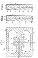
- la Fig. 2 est une vue en coupe du doublet de la Fig. 1, suivant la ligne II-II,
- la Fig. 3 est une vue en coupe du doublet de Fig. 1, suivant la ligne III-III,
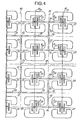
- la Fig. 4 est une vue partielle en plan d'un réseau à deux dimensions de doublets suivant la Fig. 1.
- Fig. 1 is a plan view of a doublet folded into plates, according to the invention,
- Fig. 2 is a sectional view of the doublet of FIG. 1, along line II-II,
- Fig. 3 is a sectional view of the doublet of FIG. 1, along line III-III,
- Fig. 4 is a partial plan view of a two-dimensional network of dipoles according to FIG. 1.
Le doublet replié de la Fig. 1 comprend un brin alimenté formé de deux demi-plaques 1 et 2 séparées par une coupure 3, un brin replié formé d'une plaque longue continue 4 et de deux portions symétriques 5 et 6 reliant respectivement, d'une part, 1 et 4 et, d'autre part, 2 et 4. D'un point de vue strictement structurel, chaque demi-plaque 1 ou 2 est une véritable plaque rectangulaire dont la longuur est voisine de la moitié de la longueur du doublet, mais étant donné leurs fonctions radioélectriques liées étroitement à leur longueur, il a paru plus commode de les désigner par le terme demi-plaque qui s'oppose au terme plaque utilisé pour le brin replié 4 qui occupe toute la longueur du doublet.The folded doublet of FIG. 1 comprises a supplied strand formed by two half-
La plaque 4 est reliée, dans sa partie centrale, à une plaque de masse 7, perpendiculaire à 4 et symétrique par rapport à l'axe de symétrie du doublet, du conducteur central 8 d'une ligne triplaque. Le conducteur central 8 est indiqué, à la Fig. 1, par des traits tirets car elle passe successivement sous 7, 4, 5 et 1, chacune des surfaces métalliques 7, 4, 5 et 1 servant de surfaces de masse d'un côté du conducteur 8. En particulier, sous la demi-plaque 1, la ligne 8 est à égale distances des côtés de 1.The plate 4 is connected, in its central part, to a ground plate 7, perpendicular to 4 and symmetrical with respect to the axis of symmetry of the dipole, of the central conductor 8 of a triplate line. The central conductor 8 is indicated in FIG. 1, by dashed lines because it passes successively under 7, 4, 5 and 1, each of
De plus, le doublet de la Fig. 1 comprend une seconde plaque longue continue 9 qui est symétrique de la plaque 4 par rapport à l'axe de symétrie 10 des deux demi-plaques 1 et 2, et deux portions symétriques 11 et 12 reliant respectivement, d'une part, 1 et 9 et, d'autre part, 2 et 9. Les portions 11 et 12 sont respectivement symétriques des portions 5 et 6 par rapport à l'axe 10.In addition, the doublet in FIG. 1 comprises a second long continuous plate 9 which is symmetrical with the plate 4 with respect to the axis of
La plaque 9 est reliée, dans sa partie centrale, à une plaque 13, perpendiculaire à 9 et symétrique de la plaque 7 par rapport à l'axe 10. Les plaques 7 et 13 font, en fait, partie d'une même grande plaque 14 qui entoure le doublet proprement dit, des ouvertures 15 et 16 en forme de haricots séparant le doublet de la plaque 14. Bien entendu, les ouvertures 15 et 16 sont symétriques par rapport à l'axe de symétrie du doublet perpendiculaire à l'axe de symétrie 10 et également par rapport à l'axe 10.The plate 9 is connected, in its central part, to a plate 13, perpendicular to 9 and symmetrical with the plate 7 with respect to the
La plaque 9, les portions 11 et 12, et la plaque 13 entraînent une symétrisation parfaite du doublet replié par rapport à l'axe 10, avec pour résultat un réduction sensible de la composante croisée.The plate 9, the
Comme le montre la coupe de la Fig. 2, le conducteur central 8 forme avec la plaque 7, d'une part, et une plaque de masse 17, d'autre part, une ligne d'alimentation triplaque. En pratique, les éléments métalliques 1, 2, 4, 5, 6, 7, 9, 11, 12, 13 et 14 forment une face d'un premier circuit imprimé 18 tandis que le conducteur central 8 forme l'autre face de ce circuit imprimé. Contre la face de 18 portant le conducteur 8, est appliqué la face nue d'un second circuit imprimé 19 dont l'autre face est revêtue uniformément de la plaque métallique 17. L'isolant des circuits imprimés 18 et 19 peut être le même, soit par exemple du polyguide de permittivité électrique relative F- r égale à 2,32. Les deux circuits peuvent avoir la même épaisseur. La plaque métallique continue 17 sert à la fois de plaque de masse pour la ligne d'alimentation triplaque et de réflecteur pour les parties rayonnantes 1 et 2 du doublet.As shown in the section of FIG. 2, the central conductor 8 forms with the plate 7, on the one hand, and a
Les évidemments 15 et 16 doivent être suffisamment grands pour éviter un couplage exagéré entre le doublet rayonnant et la plaque de masse 14 de la ligne triplaque.The
A partir de la plaque 7, le conducteur central 8 est prolongé successivement sous une moitié de la plaque 4 (vers la portion 5), puis sous la portion 5, puis sous la demi-plaque 1 et, enfin, après passage sous la coupure 3, sous une partie de la demi-plaque 2. Bien entendu, chacun des différents segments constituant le conducteur central se trouve toujours sous l'axe de symétrie de la plaque qui le recouvre. Le positionnement mécanique précis des deux faces du circuit imprimé 18 est obtenu en utilisant les techniques classiques de fabrications des circuits imprimés. A noter que, comme la surface métallique 17 est continue, le positionnement du circuit 19 par rapport au circuit 18 n'est pas critique.From the plate 7, the central conductor 8 is successively extended under one half of the plate 4 (towards the portion 5), then under the
La distance entre le bout 20 du conducteur 8 et le milieu de la coupure 3 est égale à un quart de longueur d'onde, c'est à dire à A14, où λ désigne la longueur dans le milieu isolant des circuits imprimés 18, 19, avec:
Ainsi, la ligne quart d'onde sous la demi-plaque 2 est ouverte ce qui ramène un court-circuit sous le bord de la demi-plaque 2 adjacent à la coupure 3. Il apparaît donc que la ligne quart d'onde permet d'éviter un passage à travers le circuit 18 et une soudure.Thus, the quarter-wave line under the half-plate 2 is open, which brings back a short circuit under the edge of the half-plate 2 adjacent to the cutoff 3. It therefore appears that the quarter-wave line allows '' avoid passing through
Le doublet des Figs. 1 à 3 peut être évidemment utilisé comme source rayonnante d'un réseau. La Fig. 4 montre comment, à partir du doublet de la Fig. 1, on peut créer un tel réseau. La partie de réseau montrée à la Fig. 4 comprend les doublets 21 à 32, identiques au doublet de la Fig. 1. Le doublet 21 est orienté comme à la Fig. 1, ce qui veut dire que le conducteur central 821 est à gauche, en regardant la figure, de l'axe 1021. Par contre, le doublet 22 est orienté symétriquement, c'est à dire que le conducteur central 822 est à droite de l'axe 1022. Dans les deux doublets 21 et 22, les demi-plaques 121 et 122 se trouve au-dessus de l'axe passant par 33. Autrement dit les doublets 21 et 22 sont symétriques par rapport à une ligne 33 parallèle aux axes 10 des doublets. Les conducteurs 821 et 822, qui sont alignés de rencontrent au point 34 et sont prolongés par un conducteur 35 qui descend sous la ligne de 34.The doublet of Figs. 1 to 3 can obviously be used as a radiating source of a network. Fig. 4 shows how, from the doublet of FIG. 1, one can create such a network. The part of the network shown in FIG. 4 includes the
Les doublets 23 et 24 se déduisent des doublets 21 et 22 par une translation dans la direction de 34 et de grandeur égale à la distance entre les centres, c'est à dire les milieux de leurs coupures, de 21 et de 22. Les conducteurs centraux 823 et 824 se rencontrent en un point 36 d'où ils sont prolongés vers le haut par 37 sous la ligne 34. Les conducteurs 35 et 37 se rencontrent au point 38 et sont prolongés vers la gauche par le conducteur 39.The
Les doublets 29 et 30 font partie d'un groupe de quatre doublets symétriques du groupe des quatres doublets 21 à 24 par rapport à une ligne 40, parallèle à 34. La distance entre les centres des doublets 22 et 29 est égale à celle qui existe entre les centres des doublets 21 et 22. Le groupe comprenant les doublets 29 et 30 est alimenté par des conducteurs centraux symétriques des conducteurs alimentant 21 à 24. Ainsi il existe un conducteur 41 semblable à 39 et qui rencontre 39 au point 42 sur la ligne 40. De là, le conducteur central est prolongé par un segment descendant 43.Doublets 29 and 30 are part of a group of four symmetrical doublets of the group of four
Les doublets 25 à 28 se déduisent des doublets 21 à 24 par translation vers le bas d'une distance égale au double de la distance entre les centres de deux doublets adjacents. Les conducteurs 8 et 826 se rencontrent au point 44 auquel aboutit le segment de conducteur central 45, identique à 35. Les conducteurs 827 et 828 se rencontrent au point 46 auquel aboutit le segment de conducteur central 47, identique à 37. Les segments 45 et 47 se rencontrent au point 48 auquel aboutit le segment de conducteur central 49, identique à 39.The
Les doublets 31 et 32 font partie d'un groupe de quatre doublets symétriques du groupe des quatre doublets 25 à 28 par rapport à la ligne 40. Le groupe est alimenté par des conducteurs centraux symétriques des conducteurs alimentant 25 à 28. Ainsi, il existe un conducteur 50 qui rencontre le conducteur 49 au point 51, sur la ligne 40. De là, le conducteur central est prolongé par un segment montant 52 qui rencontre le segment descendant 43 au point 53 auquel aboutit un segment de conducteur central 54.The
La description qui précède permet à l'homme de l'art comment après avoir associé deux doublets, on en associe quatre, puis seize pour former un réseau où les centres des doublets coïncident avec les points de croisement des lignes horizontales et verticales d'une matrice carrée. On pourra vérifier qu'à partir du point 53 jusqu'aux conducteurs 8. de chaque doublet le trajet parcouru est le même. Dans le sens horizontal, le passage d'un groupe de 2p doublets au suivant se fait par symétrie tandis que, dans le sens vertical, le passage du groupe de 2P doublets au suivant se fait par translation en ce qui concerne les doublets proprement dits et par symétrie en ce qui concerne leurs conducteurs d'alimentation. Ces remarques permettent à l'homme de l'art de comprendre comment le réseau de 24 doublets peut être étendu à 2 5, 2 6, etc.The above description allows those skilled in the art how after having associated two doublets, one associates four, then sixteen to form a network where the centers of the doublets coincide with the crossing points of the horizontal and vertical lines of a square matrix. We can verify that from point 53 to conductors 8. of each doublet the path traveled is the same. In the horizontal direction, the passage of a group of 2 p doublets to the next is done by symmetry while, in the vertical direction, the passage of the group of 2 P doublets to the next is by translation as regards the doublets properly said and by symmetry with regard to their supply conductors. These remarks allow those skilled in the art to understand how the network of 2 4 doublets can be extended to 2 5 , 2 6 , etc.
A titre indicatif, pour un doublet, suivant l'invention, prévu pour fonctionner dans la bande de fréquences de 11 à 12,4 GHz, la longueur du doublet est de 8,5 mm, soit sensiblement égale à λ/2, où A est la longueur d'onde dans le diélectrique à la fréquence moyenne de la bande. On rappelle que l'on a choisi, pour 18 et 19, un diélectrique pour lequel 6 r vaut 2,32. La largeur des demi-plaques 1 et 2 est de 3 mm et la distance du doublet au plan réflecteur 17 de 3,2 mm, soit environ 0,19 λ. La largeur du conducteur central 8 est de 0,5 mm. Les évidements 15 et 16 ont une longueur de l'ordre de 16 mm et une largeur maximale de l'ordre de 6,5 mm. La largeur de la coupure 3 est égale à 0,35 mm. La largeur des parties 7 et 13 de l'ordre de 3 mm. Les intervalles entre les parties 4 et 9 et les demi-plaques 1 et 2 ont une largeur de 0,5 mm. La largeur de 4 ou 9 est de 1 mm, ainsi que les largeurs des parties 5, 6, 11 et 12. Les épaisseurs des circuits 18 et 19 sont de 1,6 mm.As an indication, for a doublet according to the invention, intended to operate in the frequency band from 11 to 12.4 GHz, the length of the doublet is 8.5 mm, ie substantially equal to λ / 2, where A is the wavelength in the dielectric at the average frequency of the band. Recall that we have chosen, for 18 and 19, a dielectric for which 6 r is 2.32. The width of the half-
Le tableau suivant donne les caractéristiques radioélectriques mesurées sur un tel doublet en fonction de la fréquence, c'est à dire le R.O.S. (Rapport d'Ondes Stationnaires) de l'impédance d'entrée rapportée à 50 ohms, les ouvertures θE et θH dans les plans E et H, le gain GM isotrope linéaire, le niveau de composante croisée N(dB) dans l'axe du rayonnement principal du doublet. Le rendement du doublet calculé à partir du gain mesuré et de la directivité obtenue par intégration des diagrammes pour sept fréquences a comme valeur moyenne 91 %, soit une perte de 0,4 dB.

Dans le réseau de la Fig. 4, les centres des doublets peuvent être placés à 22 mm; les largeurs des conducteurs 35, 37, 45, 47, 39, 41, 49, 50, 43 et 52 peuvent être choisies égales à 1,1 mm et la largeur du conducteur 54 égale à 2,3 mm. Les impédances des conducteurs de 2,3 mm, 1,1 mm et de 0,5 mm sont respectivement de 50 ohms, 75 ohms et de 102,5 ohms.In the network of FIG. 4, the centers of the doublets can be placed at 22 mm; the widths of the
Claims (5)
Applications Claiming Priority (2)
| Application Number | Priority Date | Filing Date | Title |
|---|---|---|---|
| FR8016620A FR2487588A1 (en) | 1980-07-23 | 1980-07-23 | DOUBLE REPLIES IN PLATES FOR VERY HIGH FREQUENCY AND NETWORKS OF SUCH DOUBLETS |
| FR8016620 | 1980-07-23 |
Publications (2)
| Publication Number | Publication Date |
|---|---|
| EP0044779A1 true EP0044779A1 (en) | 1982-01-27 |
| EP0044779B1 EP0044779B1 (en) | 1985-11-13 |
Family
ID=9244607
Family Applications (1)
| Application Number | Title | Priority Date | Filing Date |
|---|---|---|---|
| EP81401135A Expired EP0044779B1 (en) | 1980-07-23 | 1981-07-16 | Folded dipoles in tri-plate technology for very high frequencies, and arrays comprising the same |
Country Status (5)
| Country | Link |
|---|---|
| US (1) | US4426649A (en) |
| EP (1) | EP0044779B1 (en) |
| JP (1) | JPS5787206A (en) |
| DE (1) | DE3172900D1 (en) |
| FR (1) | FR2487588A1 (en) |
Cited By (7)
| Publication number | Priority date | Publication date | Assignee | Title |
|---|---|---|---|---|
| EP0085486A1 (en) * | 1982-01-15 | 1983-08-10 | The Marconi Company Limited | Antenna arrangement |
| US4847626A (en) * | 1987-07-01 | 1989-07-11 | Motorola, Inc. | Microstrip balun-antenna |
| GB2212665A (en) * | 1987-11-23 | 1989-07-26 | Gen Electric Co Plc | Slot antenna |
| GB2249924A (en) * | 1990-09-07 | 1992-05-20 | Marconi Electronic Devices | Moving vehicle transponder |
| GB2261554A (en) * | 1991-11-15 | 1993-05-19 | Northern Telecom Ltd | Flat plate antenna. |
| US5691734A (en) * | 1994-06-01 | 1997-11-25 | Alan Dick & Company Limited | Dual polarizating antennae |
| FR2761532A1 (en) * | 1997-03-31 | 1998-10-02 | Samsung Electronics Co Ltd | CAVITY MICRO-TAPE DIPOLAR NETWORK ANTENNA |
Families Citing this family (29)
| Publication number | Priority date | Publication date | Assignee | Title |
|---|---|---|---|---|
| US4477813A (en) * | 1982-08-11 | 1984-10-16 | Ball Corporation | Microstrip antenna system having nonconductively coupled feedline |
| US4613868A (en) * | 1983-02-03 | 1986-09-23 | Ball Corporation | Method and apparatus for matched impedance feeding of microstrip-type radio frequency antenna structure |
| US4590478A (en) * | 1983-06-15 | 1986-05-20 | Sanders Associates, Inc. | Multiple ridge antenna |
| US4686536A (en) * | 1985-08-15 | 1987-08-11 | Canadian Marconi Company | Crossed-drooping dipole antenna |
| FR2598036B1 (en) | 1986-04-23 | 1988-08-12 | France Etat | PLATE ANTENNA WITH DOUBLE CROSS POLARIZATIONS |
| JPS63258102A (en) * | 1987-04-15 | 1988-10-25 | Matsushita Electric Works Ltd | Plane antenna |
| JPS6365703A (en) * | 1986-09-05 | 1988-03-24 | Matsushita Electric Works Ltd | Planar antenna |
| US5005019A (en) * | 1986-11-13 | 1991-04-02 | Communications Satellite Corporation | Electromagnetically coupled printed-circuit antennas having patches or slots capacitively coupled to feedlines |
| FR2613876B1 (en) * | 1987-04-10 | 1989-10-20 | Lmt Radio Professionelle | PLANE ANTENNA WITH NETWORK, SELF-PROTECTED AND TRANSPORTABLE |
| JPH07120893B2 (en) * | 1987-04-15 | 1995-12-20 | 松下電工株式会社 | Planar antenna |
| JPH02104006A (en) * | 1989-06-28 | 1990-04-17 | Matsushita Electric Works Ltd | Planar antenna |
| US5187490A (en) * | 1989-08-25 | 1993-02-16 | Hitachi Chemical Company, Ltd. | Stripline patch antenna with slot plate |
| US5278569A (en) * | 1990-07-25 | 1994-01-11 | Hitachi Chemical Company, Ltd. | Plane antenna with high gain and antenna efficiency |
| FR2669776B1 (en) * | 1990-11-23 | 1993-01-22 | Thomson Csf | SLOTTED MICROWAVE ANTENNA WITH LOW THICKNESS STRUCTURE. |
| JPH0594133U (en) * | 1992-05-29 | 1993-12-21 | 株式会社ダイフク | ID tag mounting structure |
| US5539414A (en) * | 1993-09-02 | 1996-07-23 | Inmarsat | Folded dipole microstrip antenna |
| JP2545737B2 (en) * | 1994-01-10 | 1996-10-23 | 郵政省通信総合研究所長 | Gaussian beam type antenna device |
| FR2727250A1 (en) * | 1994-11-22 | 1996-05-24 | Brachat Patrice | MONOPOLY BROADBAND ANTENNA IN UNIPLANAR PRINTED TECHNOLOGY AND TRANSMITTING AND / OR RECEIVING DEVICE INCORPORATING SUCH ANTENNA |
| US5986610A (en) * | 1995-10-11 | 1999-11-16 | Miron; Douglas B. | Volume-loaded short dipole antenna |
| AU7999500A (en) * | 1999-10-12 | 2001-04-23 | Arc Wireless Solutions, Inc. | Compact dual narrow band microstrip antenna |
| FR2819109A1 (en) * | 2001-01-04 | 2002-07-05 | Cit Alcatel | MULTI-BAND ANTENNA FOR MOBILE DEVICES |
| CN1494749A (en) * | 2001-04-23 | 2004-05-05 | Fci | Compact antenna block for wireless device |
| US7830322B1 (en) * | 2007-09-24 | 2010-11-09 | Impinj, Inc. | RFID reader antenna assembly |
| KR100960044B1 (en) * | 2008-10-21 | 2010-05-31 | 국방과학연구소 | Resonator with 3-dimensional DGSdefected ground structure in transmission line |
| US8106846B2 (en) * | 2009-05-01 | 2012-01-31 | Applied Wireless Identifications Group, Inc. | Compact circular polarized antenna |
| US8618998B2 (en) | 2009-07-21 | 2013-12-31 | Applied Wireless Identifications Group, Inc. | Compact circular polarized antenna with cavity for additional devices |
| US8860617B1 (en) * | 2011-07-08 | 2014-10-14 | Trivec-Avant Corporation | Multiband embedded antenna |
| RU2568328C2 (en) * | 2013-12-10 | 2015-11-20 | Дмитрий Алексеевич Антропов | Doublet antenna |
| JP6498367B1 (en) * | 2018-05-23 | 2019-04-10 | 三菱電機株式会社 | Antenna device and array antenna |
Citations (8)
| Publication number | Priority date | Publication date | Assignee | Title |
|---|---|---|---|---|
| DE1068314B (en) * | 1956-05-22 | 1959-11-05 | Societe Technique dAppl'ication et de Recherche Electronique S.T.A.R.E.C., Nogent-sur-Marne, Seine (Frankreich) | Half-wavelength antenna made of a metallic cylindrical surface |
| US3172111A (en) * | 1962-08-30 | 1965-03-02 | Louis D Breetz | Multi-polarized single element radiator |
| FR2050408A1 (en) * | 1969-07-01 | 1971-04-02 | Rca Corp | |
| US3813674A (en) * | 1972-01-05 | 1974-05-28 | Secr Defence | Cavity backed dipole-slot antenna for circular polarization |
| FR2231128A1 (en) * | 1973-05-21 | 1974-12-20 | Dubost Gerard | Folded dipole network - is used for wide band directional system capable of handling circular polarisations |
| FR2311422A1 (en) * | 1975-05-15 | 1976-12-10 | France Etat | DOUBLET FOLDED IN PLATES |
| US4097868A (en) * | 1976-12-06 | 1978-06-27 | The United States Of America As Represented By The Secretary Of The Army | Antenna for combined surveillance and foliage penetration radar |
| GB2029112A (en) * | 1978-06-08 | 1980-03-12 | Murphy A | Television aerial |
Family Cites Families (2)
| Publication number | Priority date | Publication date | Assignee | Title |
|---|---|---|---|---|
| BE533239A (en) | 1952-05-08 | |||
| FR2298200A1 (en) | 1975-01-17 | 1976-08-13 | France Etat | DOUBLET FOLDED THICK TUNABLE IN A FREQUENCY BAND OF TWO OCTAVES |
-
1980
- 1980-07-23 FR FR8016620A patent/FR2487588A1/en active Granted
-
1981
- 1981-07-16 DE DE8181401135T patent/DE3172900D1/en not_active Expired
- 1981-07-16 EP EP81401135A patent/EP0044779B1/en not_active Expired
- 1981-07-20 US US06/284,702 patent/US4426649A/en not_active Expired - Fee Related
- 1981-07-23 JP JP56114526A patent/JPS5787206A/en active Granted
Patent Citations (8)
| Publication number | Priority date | Publication date | Assignee | Title |
|---|---|---|---|---|
| DE1068314B (en) * | 1956-05-22 | 1959-11-05 | Societe Technique dAppl'ication et de Recherche Electronique S.T.A.R.E.C., Nogent-sur-Marne, Seine (Frankreich) | Half-wavelength antenna made of a metallic cylindrical surface |
| US3172111A (en) * | 1962-08-30 | 1965-03-02 | Louis D Breetz | Multi-polarized single element radiator |
| FR2050408A1 (en) * | 1969-07-01 | 1971-04-02 | Rca Corp | |
| US3813674A (en) * | 1972-01-05 | 1974-05-28 | Secr Defence | Cavity backed dipole-slot antenna for circular polarization |
| FR2231128A1 (en) * | 1973-05-21 | 1974-12-20 | Dubost Gerard | Folded dipole network - is used for wide band directional system capable of handling circular polarisations |
| FR2311422A1 (en) * | 1975-05-15 | 1976-12-10 | France Etat | DOUBLET FOLDED IN PLATES |
| US4097868A (en) * | 1976-12-06 | 1978-06-27 | The United States Of America As Represented By The Secretary Of The Army | Antenna for combined surveillance and foliage penetration radar |
| GB2029112A (en) * | 1978-06-08 | 1980-03-12 | Murphy A | Television aerial |
Non-Patent Citations (3)
| Title |
|---|
| Frequenz, Vol. 31, Novembre 1977, E. HORMANN et al.: "Experimental Analysis and Selection of Airborne Antennas for Aircraft-to-Satellite Communication Systems", pages 336-341 Berlin, DE * figure 3 * * |
| H. JASIK "Antenna Engineering Handbook", Premiere Edition, 1961 McGraw-Hill Book Company New York, US * page 3-14, lignes 9-11; ligure 3-20; figure 3-22(b) * * |
| Union des Associations Techniques Internationales et al Societe Francaise des Electroniciens et des Radioelectriciens, Communications Presentee au Collogue International 1'Espace et la Communication, 1971 Paris, FR pages 216-225 * figure &, figure 6 * * |
Cited By (12)
| Publication number | Priority date | Publication date | Assignee | Title |
|---|---|---|---|---|
| EP0085486A1 (en) * | 1982-01-15 | 1983-08-10 | The Marconi Company Limited | Antenna arrangement |
| US4847626A (en) * | 1987-07-01 | 1989-07-11 | Motorola, Inc. | Microstrip balun-antenna |
| GB2212665A (en) * | 1987-11-23 | 1989-07-26 | Gen Electric Co Plc | Slot antenna |
| GB2212665B (en) * | 1987-11-23 | 1991-09-04 | Gen Electric Co Plc | A slot antenna |
| GB2249924A (en) * | 1990-09-07 | 1992-05-20 | Marconi Electronic Devices | Moving vehicle transponder |
| GB2249924B (en) * | 1990-09-07 | 1994-06-15 | Marconi Electronic Devices | Moving vehicle transponder |
| GB2261554A (en) * | 1991-11-15 | 1993-05-19 | Northern Telecom Ltd | Flat plate antenna. |
| GB2261554B (en) * | 1991-11-15 | 1995-05-24 | Northern Telecom Ltd | Flat plate antenna |
| US5691734A (en) * | 1994-06-01 | 1997-11-25 | Alan Dick & Company Limited | Dual polarizating antennae |
| FR2761532A1 (en) * | 1997-03-31 | 1998-10-02 | Samsung Electronics Co Ltd | CAVITY MICRO-TAPE DIPOLAR NETWORK ANTENNA |
| GB2323970A (en) * | 1997-03-31 | 1998-10-07 | Samsung Electronics Co Ltd | A cavity-backed microstrip dipole antenna array |
| GB2323970B (en) * | 1997-03-31 | 2001-12-05 | Samsung Electronics Co Ltd | A cavity-backed microstrip dipole antenna array |
Also Published As
| Publication number | Publication date |
|---|---|
| US4426649A (en) | 1984-01-17 |
| JPH0139242B2 (en) | 1989-08-18 |
| EP0044779B1 (en) | 1985-11-13 |
| FR2487588A1 (en) | 1982-01-29 |
| FR2487588B1 (en) | 1984-11-02 |
| DE3172900D1 (en) | 1985-12-19 |
| JPS5787206A (en) | 1982-05-31 |
Similar Documents
| Publication | Publication Date | Title |
|---|---|---|
| EP0044779B1 (en) | Folded dipoles in tri-plate technology for very high frequencies, and arrays comprising the same | |
| EP2510574B1 (en) | Microwave transition device between a microstrip line and a rectangular waveguide | |
| EP0108463B1 (en) | Radiating element for cross-polarized microwave signals and planar antenna consisting of an array of such elements | |
| EP0243289B1 (en) | Plate antenna with two crossed polarizations | |
| EP0205212B1 (en) | Modular microwave antenna units and antenna composed of such units | |
| EP0089084B1 (en) | Flat microwave antenna structure | |
| EP0923157B1 (en) | Antenna realised according to microstrip technique and device incorporating this antenna | |
| EP0145597B1 (en) | Plane periodic antenna | |
| EP0800210B1 (en) | Compact microwave module | |
| FR2772517A1 (en) | MULTI-FREQUENCY ANTENNA MADE ACCORDING TO MICRO-TAPE TECHNIQUE AND DEVICE INCLUDING THIS ANTENNA | |
| EP1172885A1 (en) | Short-circuit microstrip antenna and dual-band transmission device including that antenna | |
| EP0923156A1 (en) | Shorted microstrip antenna and apparatus using the same | |
| EP1042845B1 (en) | Antenna | |
| EP0082751B1 (en) | Microwave radiator and its use in an electronically scanned antenna | |
| FR2645353A1 (en) | FLAT ANTENNA | |
| EP3529852B1 (en) | Multilayer waveguide comprising at least one device for transition between the layers of this multilayer waveguide | |
| FR2989842A1 (en) | SLOW-WAVE RADIOFREQUENCY PROPAGATION LINE | |
| EP2432072B1 (en) | Wideband balun on a multilayer circuit for a network antenna | |
| EP0484241B1 (en) | Printed circuit antenna for a dual polarized antenna array | |
| EP0477102B1 (en) | Directional network with adjacent radiator elements for radio communication system and unit with such a directional network | |
| EP0557176B1 (en) | Feeding device for a plate antenna with two crossed polarizations and array equipped with such a device | |
| EP0983616B1 (en) | Method and device for connecting two millimetric elements | |
| EP0283396A1 (en) | Junction between a triplate line and a microstrip line and application thereof | |
| FR2690789A1 (en) | Antenna array for radar - has multiple element conducting lines mounted in triangular horn section with vertical stacking and fed centrally | |
| FR2535531A1 (en) | Electromagnetic wave radiator and its use in an antenna with electronic scanning. |
Legal Events
| Date | Code | Title | Description |
|---|---|---|---|
| PUAI | Public reference made under article 153(3) epc to a published international application that has entered the european phase |
Free format text: ORIGINAL CODE: 0009012 |
|
| AK | Designated contracting states |
Designated state(s): BE DE GB SE |
|
| 17P | Request for examination filed |
Effective date: 19820722 |
|
| GRAA | (expected) grant |
Free format text: ORIGINAL CODE: 0009210 |
|
| AK | Designated contracting states |
Designated state(s): BE DE GB SE |
|
| REF | Corresponds to: |
Ref document number: 3172900 Country of ref document: DE Date of ref document: 19851219 |
|
| PLBE | No opposition filed within time limit |
Free format text: ORIGINAL CODE: 0009261 |
|
| STAA | Information on the status of an ep patent application or granted ep patent |
Free format text: STATUS: NO OPPOSITION FILED WITHIN TIME LIMIT |
|
| 26N | No opposition filed | ||
| PGFP | Annual fee paid to national office [announced via postgrant information from national office to epo] |
Ref country code: SE Payment date: 19930609 Year of fee payment: 13 |
|
| PGFP | Annual fee paid to national office [announced via postgrant information from national office to epo] |
Ref country code: BE Payment date: 19930902 Year of fee payment: 13 |
|
| PG25 | Lapsed in a contracting state [announced via postgrant information from national office to epo] |
Ref country code: SE Effective date: 19940717 |
|
| PG25 | Lapsed in a contracting state [announced via postgrant information from national office to epo] |
Ref country code: BE Effective date: 19940731 |
|
| BERE | Be: lapsed |
Owner name: ETABLISSEMENT PUBLIC DE DIFFUSION Effective date: 19940731 Owner name: L' ETAT FRANCAIS REPRESENTE PAR LE SECRETAIRE D'ET Effective date: 19940731 |
|
| EUG | Se: european patent has lapsed |
Ref document number: 81401135.9 Effective date: 19950210 |
|
| EUG | Se: european patent has lapsed |
Ref document number: 81401135.9 |
|
| PGFP | Annual fee paid to national office [announced via postgrant information from national office to epo] |
Ref country code: GB Payment date: 20000629 Year of fee payment: 20 |
|
| PGFP | Annual fee paid to national office [announced via postgrant information from national office to epo] |
Ref country code: DE Payment date: 20000705 Year of fee payment: 20 |
|
| PG25 | Lapsed in a contracting state [announced via postgrant information from national office to epo] |
Ref country code: GB Free format text: LAPSE BECAUSE OF EXPIRATION OF PROTECTION Effective date: 20010715 |
|
| REG | Reference to a national code |
Ref country code: GB Ref legal event code: PE20 Effective date: 20010715 |