EP0044773A1 - Ground vehicle with electronic control - Google Patents
Ground vehicle with electronic control Download PDFInfo
- Publication number
- EP0044773A1 EP0044773A1 EP81401119A EP81401119A EP0044773A1 EP 0044773 A1 EP0044773 A1 EP 0044773A1 EP 81401119 A EP81401119 A EP 81401119A EP 81401119 A EP81401119 A EP 81401119A EP 0044773 A1 EP0044773 A1 EP 0044773A1
- Authority
- EP
- European Patent Office
- Prior art keywords
- wheels
- vehicle
- vehicle according
- pair
- wheel
- Prior art date
- Legal status (The legal status is an assumption and is not a legal conclusion. Google has not performed a legal analysis and makes no representation as to the accuracy of the status listed.)
- Granted
Links
Images


Classifications
-
- B—PERFORMING OPERATIONS; TRANSPORTING
- B62—LAND VEHICLES FOR TRAVELLING OTHERWISE THAN ON RAILS
- B62D—MOTOR VEHICLES; TRAILERS
- B62D11/00—Steering non-deflectable wheels; Steering endless tracks or the like
- B62D11/02—Steering non-deflectable wheels; Steering endless tracks or the like by differentially driving ground-engaging elements on opposite vehicle sides
- B62D11/04—Steering non-deflectable wheels; Steering endless tracks or the like by differentially driving ground-engaging elements on opposite vehicle sides by means of separate power sources
-
- B—PERFORMING OPERATIONS; TRANSPORTING
- B60—VEHICLES IN GENERAL
- B60L—PROPULSION OF ELECTRICALLY-PROPELLED VEHICLES; SUPPLYING ELECTRIC POWER FOR AUXILIARY EQUIPMENT OF ELECTRICALLY-PROPELLED VEHICLES; ELECTRODYNAMIC BRAKE SYSTEMS FOR VEHICLES IN GENERAL; MAGNETIC SUSPENSION OR LEVITATION FOR VEHICLES; MONITORING OPERATING VARIABLES OF ELECTRICALLY-PROPELLED VEHICLES; ELECTRIC SAFETY DEVICES FOR ELECTRICALLY-PROPELLED VEHICLES
- B60L15/00—Methods, circuits, or devices for controlling the traction-motor speed of electrically-propelled vehicles
- B60L15/20—Methods, circuits, or devices for controlling the traction-motor speed of electrically-propelled vehicles for control of the vehicle or its driving motor to achieve a desired performance, e.g. speed, torque, programmed variation of speed
- B60L15/2036—Electric differentials, e.g. for supporting steering vehicles
-
- B—PERFORMING OPERATIONS; TRANSPORTING
- B60—VEHICLES IN GENERAL
- B60L—PROPULSION OF ELECTRICALLY-PROPELLED VEHICLES; SUPPLYING ELECTRIC POWER FOR AUXILIARY EQUIPMENT OF ELECTRICALLY-PROPELLED VEHICLES; ELECTRODYNAMIC BRAKE SYSTEMS FOR VEHICLES IN GENERAL; MAGNETIC SUSPENSION OR LEVITATION FOR VEHICLES; MONITORING OPERATING VARIABLES OF ELECTRICALLY-PROPELLED VEHICLES; ELECTRIC SAFETY DEVICES FOR ELECTRICALLY-PROPELLED VEHICLES
- B60L50/00—Electric propulsion with power supplied within the vehicle
- B60L50/50—Electric propulsion with power supplied within the vehicle using propulsion power supplied by batteries or fuel cells
- B60L50/60—Electric propulsion with power supplied within the vehicle using propulsion power supplied by batteries or fuel cells using power supplied by batteries
-
- Y—GENERAL TAGGING OF NEW TECHNOLOGICAL DEVELOPMENTS; GENERAL TAGGING OF CROSS-SECTIONAL TECHNOLOGIES SPANNING OVER SEVERAL SECTIONS OF THE IPC; TECHNICAL SUBJECTS COVERED BY FORMER USPC CROSS-REFERENCE ART COLLECTIONS [XRACs] AND DIGESTS
- Y02—TECHNOLOGIES OR APPLICATIONS FOR MITIGATION OR ADAPTATION AGAINST CLIMATE CHANGE
- Y02T—CLIMATE CHANGE MITIGATION TECHNOLOGIES RELATED TO TRANSPORTATION
- Y02T10/00—Road transport of goods or passengers
- Y02T10/60—Other road transportation technologies with climate change mitigation effect
- Y02T10/64—Electric machine technologies in electromobility
-
- Y—GENERAL TAGGING OF NEW TECHNOLOGICAL DEVELOPMENTS; GENERAL TAGGING OF CROSS-SECTIONAL TECHNOLOGIES SPANNING OVER SEVERAL SECTIONS OF THE IPC; TECHNICAL SUBJECTS COVERED BY FORMER USPC CROSS-REFERENCE ART COLLECTIONS [XRACs] AND DIGESTS
- Y02—TECHNOLOGIES OR APPLICATIONS FOR MITIGATION OR ADAPTATION AGAINST CLIMATE CHANGE
- Y02T—CLIMATE CHANGE MITIGATION TECHNOLOGIES RELATED TO TRANSPORTATION
- Y02T10/00—Road transport of goods or passengers
- Y02T10/60—Other road transportation technologies with climate change mitigation effect
- Y02T10/70—Energy storage systems for electromobility, e.g. batteries
-
- Y—GENERAL TAGGING OF NEW TECHNOLOGICAL DEVELOPMENTS; GENERAL TAGGING OF CROSS-SECTIONAL TECHNOLOGIES SPANNING OVER SEVERAL SECTIONS OF THE IPC; TECHNICAL SUBJECTS COVERED BY FORMER USPC CROSS-REFERENCE ART COLLECTIONS [XRACs] AND DIGESTS
- Y02—TECHNOLOGIES OR APPLICATIONS FOR MITIGATION OR ADAPTATION AGAINST CLIMATE CHANGE
- Y02T—CLIMATE CHANGE MITIGATION TECHNOLOGIES RELATED TO TRANSPORTATION
- Y02T10/00—Road transport of goods or passengers
- Y02T10/60—Other road transportation technologies with climate change mitigation effect
- Y02T10/72—Electric energy management in electromobility
Definitions
- the present invention relates to an electronically controlled land vehicle.
- the invention also relates to a piloting method applicable to such a vehicle.
- each drive wheel is made integral with a variable speed electric motor whose torque is adjusted by a suitable action of the driver on a guide member such as lever or lever.
- the driver chooses at any time the torque applied to each wheel, in order to obtain the changes in trajectory and speed that he wishes to impose on his vehicle, or in order to maintain it on a given trajectory, straight or curvilinear.
- the vehicle has one or two freely steerable wheels (for example, a non-guided front wheel in the case of a vehicle of the tricycle type) the position of this or these wheels, not known to the driver, may disturb the trajectory, and the correction that the driver must make can only intervene after the discovery of the unexpected deviation of his vehicle; this is particularly sensitive during maneuvers requiring successive changes of direction of market.
- the driver's intervention, through perception, reflection and action introduces a delay prejudicial to safe and precise driving.
- the present invention aims to produce a vehicle which is insensitive to disturbances such as those mentioned above, as well as a control method applicable to such a vehicle.
- the electronically controlled land vehicle comprises at least one pair of side wheels driven by respective electric motors, means for communicating to each of the wheels of this pair its own driving action, and a source of 'electric energy. It is characterized in that it comprises a computer associated with a reference clock, connected on the one hand to a control member to receive instructions for modification of trajectory and speed, and on the other hand to position detectors relative to the fixed and mobile parts of the respective driving wheels, and finally to the control members of the respective motors of the wheels for transmitting to these members orders determining the exchange of energy with the respective wheels with a view to giving them their own differential acceleration to enforce the instructions for changes to the trajectory and speed.
- the computer actuates the wheels symmetrically or differentially to ensure compliance with a trajectory and a speed corresponding to a previously given setpoint. This action has the effect of alleviating fortuitous deviations caused by various incidents, without the pilot even having to note these deviations.
- the computer comprises as many programming blocks as there are drive wheels, and these blocks are interconnected by links allowing them to exchange their information.
- the wheel motors are variable reluctance motors each comprising a toothed rotor cooperating with a toothed stator provided with windings connected to a source of electrical energy by means of switching members connected to the programming block to send pulses of predetermined intensity and duration to the windings.
- the vehicle comprises a scanner of the intensity of each pulse delivered to the engine, and this scanner is connected to a comparison stage with a reference value of the intensity produced by the calculation stage.
- the intensity setpoint is produced by the computer as a function of the actual measured speed and the desired speed.
- the computer according to the comparison of the intensities, modulates the chopping of the pulses to make the actual intensity equal to the set intensity.
- the vehicle also advantageously comprises a relative position detector of the fixed and mobile parts of each wheel, and this stage is connected to the programming block which determines the phase difference between a reference position of the motor and the start of the electrical pulse in the windings.
- the computer adjusts this phase difference to define slow or fast walking, or braking adapted to slow or fast speed.
- the vehicle piloting method in particular for ensuring the registration in a given curve of a vehicle comprising at least one pair of independent driving side wheels, and means for communicating to each of the wheels of this pair a clean driving action, is characterized in that, to cause the vehicle to turn, a predetermined difference in acceleration is ensured between the wheels of the same pair, the greatest acceleration being communicated to the wheel located outside the curve. This difference is maintained until the radius of curvature of the trajectory of the vehicle corresponds to that of the circular part of the curve to be described, after which the accelerations communicated to the wheels are kept equal, until causes an increase in the radius of curvature corresponding to the exit from the turn.
- a vehicle is carried by a pair of driving wheels 1 and a steerable tricycle wheel 2.
- the wheels 1 are driving and each comprise a serrated rotor 3 cooperating with a stator 4 secured to the vehicle (FIG. 2) and provided with windings to constitute a synchronous motor with variable reluctance.
- the number of stator switches per wheel revolution is relatively high, from a few tens to several hundred.
- the stator windings 4 are connected to a battery 5 by means of a switch 6 which, in the example described, is constituted by thyristors controlled from a programming block 7 associated with a clock 8 by l line 9.
- the wheels 1 are also provided with detection members constituted by a number of photoelectric cells 11 fixed to the stator and cooperating with teeth 12 formed on the rotor (FIGS. 2 and 3), to detect the relative positions of the stator and rotor.
- a fitness stage 13 (FIG. 4)
- a detection stage 14 which measures the duration between the pulses emitted by the cells and which also detects the direction of rotation of the wheel 1, thanks to the fact that the number of cells is greater than one.
- This duration and direction information is transmitted to block 7 in digital form respectively by lines 15 and 16.
- a control member 17 ( Figures 1 and 5) comprises a lever 18 tiltable in all directions, and the end of which carries a lamp 19 arranged to illuminate a group 21 of photoelectric cells. It is understood that, according to the direction of the inclination given to the lever 18 (front, rear, left, right), and according to the inclination angle, the differential illumination of the cells will be modified, and that the resulting signal will define at both a direction of travel and an acceleration, the vehicle direction signal corresponding to different acceleration instructions sent respectively to block 7 and to a similar block (not shown) connected to the other wheel according to a diagram similar to that of FIG. 4. A link 22 between these two blocks allows them to exchange their information, their assembly constituting a computer.
- Direction information reaches block 7 via a detection stage 23, while the acceleration information passes through an analog-digital converter 24.
- block 7 develops an electrical intensity setpoint value of the pulses supplied to the stator and applies this value to a comparison stage 25 which compares it to the actual intensity measured by a scanner 26.
- a link 27 makes it possible to communicate the information relating to the result of this comparison to block 7.
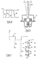
- block 7 modifies, by lines 9, the operating mode of the thyristors. It is in fact understood that the average intensity Im (FIG. 6) during a pulse 28 depends on the instant of the ignitions 29 of the thyristors during this pulse.
- the information relating to the instants of ignition of the thyristors are communicated to the detection stage 14 by a link 31, which allows the stage 14 to determine the phase difference between the start of a pulse 28 and the instant when the wheel passes through a reference position, this instant being defined by one of the photocells 11.
- the square wave signal D emitted by the cell is such that its rising edge occurs when a tooth 32 of the rotor passes exactly in front of a tooth 33 of the stator (FIG. 7-C).
- phase difference information thus produced is transmitted to block 7 by a link 34.
- block 7 modifies the phase difference in order to respect this instruction.
- the pulse is sent at time t i , when tooth 32 of the rotor enters the area of attraction of the stator (position A).
- position B At high speed, we give a certain advance to ignition (position B) by switching on at time t 2-
- Block 7 also includes a memory 34 with modifiable content in which are stored a certain number of permanent instructions, in particular safety instructions, such as speed limits, or a radius of curvature path limit as a function of speed.
- safety instructions such as speed limits, or a radius of curvature path limit as a function of speed.
- the pilot gives a speed and trajectory modification instruction by means of the control member 17, then he returns this member to the neutral position. From this moment, the block 7 and that relating to the other wheel will make these instructions respect despite the vagaries of the journey without intervention of the pilot.
- the computer will modify the power transmitted to the wheels as soon as it notices a tendency to a variation in speed. The same goes for the trajectory. If the setpoint corresponds to a straight line, any initiation of deviation caused for example by an unevenness of the ground will result in an unequal speed of the wheels 1. This difference in speed noted by the computer will cause a differential acceleration of the wheels which will tend to restore instantly the straight path.
- the role of the pilot is limited only to modifying the set values when he wishes.
- control member 17 can be constituted by a stationary handle sensitive to the pressure exerted, by means of strain gauges.
Abstract
Véhicule terrestre à commande électronique comportant au moins une paire de roues latérales (1) motrices et indépendantes, et procédé de pilotage d'un tel véhicule. Les roues (1) sont actionnées indépendamment par des moteurs commandés par des impulsions issues d'un générateur (6) lui-même commandé par un calculateur (7). Le calculateur (7) reçoit des ordres d'un transducteur (17) muni d'un levier de manoeuvre (18). Il reçoit en retour un signal de position des roues obtenu par des détecteurs (11) et il est agencé pour appliquer aux roues des accélérations respectives dont la différence est fonction de l'inclinaison du levier (18). Application à la conduite des véhicules, notamment routiers.Land vehicle with electronic control comprising at least one pair of lateral and independent driving wheels (1), and method for driving such a vehicle. The wheels (1) are independently actuated by motors controlled by pulses from a generator (6) itself controlled by a computer (7). The computer (7) receives orders from a transducer (17) provided with an operating lever (18). It receives in return a wheel position signal obtained by detectors (11) and it is arranged to apply to the wheels respective accelerations, the difference of which depends on the inclination of the lever (18). Application to driving vehicles, especially road vehicles.
Description
La présente invention concerne un véhicule terrestre à commande électronique.The present invention relates to an electronically controlled land vehicle.
L'invention concerne également un procédé de pilotage applicable à un tel véhicule.The invention also relates to a piloting method applicable to such a vehicle.
On a ici en vue des véhicules comprenant au moins une paire de roues latérales motrices et indépendantes à chacune desquelles on peut appliquer une action motrice propre.Here we have in view vehicles comprising at least one pair of independent driving side wheels to each of which we can apply a specific driving action.
Il est connu d'assurer le guidage de véhicules terrestres en réglant indépendamment le couple, positif ou négatif, appliqué aux roues latérales. A cette fin, chaque roue motrice est rendue solidaire d'un moteur électrique à vitesse variable dont le couple est réglé par une action convenable du conducteur sur un organe de guidage tel que levier ou manette. Le conducteur fait choix à tout moment du couple appliqué à chaque roue, afin d'obtenir les modifications de trajectoire et de vitesse qu'il désire imposer à son véhicule, ou afin de le maintenir sur une trajectoire donnée, rectiligne ou curviligne. De tels dispositifs et le mode de conduite qu'ils impliquent présentent divers inconvénients du fait que le conducteur doit corriger en intervenant personnellement toute modification de trajectoire due à des circonstances indépendantes de sa volonté: par exemple, une modification du dévers transversal de la chaussée modifie la trajectoire qui doit être corrigée; un obstacle rencontré par une seule roue, ou une zone de moindre adhérence, produit le même effet. En outre, si le véhicule comporte une ou deux roues librement orientables (par exemple, une roue avant non guidée dans le cas d'un véhicule du genre tricycle) la position de cette ou de ces roues, non connue du conducteur, peut perturber la trajectoire, et la correction que doit effectuer le conducteur ne peut intervenir qu'après la constatation de l'écart imprévu de son véhicule; ceci est particulièrement sensible lors de manoeuvres nécessitant des changements successifs de sens de marche. Or, l'intervention du conducteur, par perception, réflexion et action, introduit un temps de retard préjudiciable à une conduite sûre et précise.It is known to guide land vehicles by independently adjusting the torque, positive or negative, applied to the side wheels. To this end, each drive wheel is made integral with a variable speed electric motor whose torque is adjusted by a suitable action of the driver on a guide member such as lever or lever. The driver chooses at any time the torque applied to each wheel, in order to obtain the changes in trajectory and speed that he wishes to impose on his vehicle, or in order to maintain it on a given trajectory, straight or curvilinear. Such devices and the driving mode they imply have various drawbacks because the driver must correct by personal intervention any change in trajectory due to circumstances beyond his control: for example, a change in the transverse slope of the road changes the trajectory to be corrected; an obstacle encountered by a single wheel, or an area of less grip, produces the same effect. In addition, if the vehicle has one or two freely steerable wheels (for example, a non-guided front wheel in the case of a vehicle of the tricycle type) the position of this or these wheels, not known to the driver, may disturb the trajectory, and the correction that the driver must make can only intervene after the discovery of the unexpected deviation of his vehicle; this is particularly sensitive during maneuvers requiring successive changes of direction of market. However, the driver's intervention, through perception, reflection and action, introduces a delay prejudicial to safe and precise driving.
La présente invention vise à réaliser un véhicule qui soit insensible aux perturbations telles que celles évoquées ci-dessus, ainsi qu'un procédé de pilotage applicable à un tel véhicule.The present invention aims to produce a vehicle which is insensitive to disturbances such as those mentioned above, as well as a control method applicable to such a vehicle.
Suivant un premier aspect de l'invention, le véhicule terrestre à commande électronique comporte au moins une paire de roues latérales entraînées par des moteurs électriques respectifs, des moyens pour communiquer à chacune des roues de cette paire une action motrice propre, et une source d'énergie électrique. Il est caractérisé en ce qu'il comprend un calculateur associé à une horloge de référence, relié d'une part à un organe de commande pour recevoir des consignes de modification de trajectoire et de vitesse, et d'autre part à des détecteurs des positions relatives des parties fixe et mobile des roues motrices respectives, et enfin à des organes de commande des moteurs respectifs des roues pour transmettre à ces organes des ordres déterminant l'échange d'énergie avec les roues respectives en vue de leur conférer une accélération différentielle propre à faire respecter les consignes de modifications de la trajectoire et de vitesse.According to a first aspect of the invention, the electronically controlled land vehicle comprises at least one pair of side wheels driven by respective electric motors, means for communicating to each of the wheels of this pair its own driving action, and a source of 'electric energy. It is characterized in that it comprises a computer associated with a reference clock, connected on the one hand to a control member to receive instructions for modification of trajectory and speed, and on the other hand to position detectors relative to the fixed and mobile parts of the respective driving wheels, and finally to the control members of the respective motors of the wheels for transmitting to these members orders determining the exchange of energy with the respective wheels with a view to giving them their own differential acceleration to enforce the instructions for changes to the trajectory and speed.
En l'absence d'action sur l'organe de commande, le calculateur actionne les roues de façon symétrique ou différentielle pour faire respecter une trajectoire et une vitesse correspondant à une consigne donnée antérieurement. Cette action a pour effet de pallier, les déviations fortuites occasionnées par des incidents divers, sans même que le pilote ait à constater ces déviations.In the absence of action on the control member, the computer actuates the wheels symmetrically or differentially to ensure compliance with a trajectory and a speed corresponding to a previously given setpoint. This action has the effect of alleviating fortuitous deviations caused by various incidents, without the pilot even having to note these deviations.
Suivant une réalisation préférée de l'invention, le calculateur comprend autant de blocs de programmation que de roues motrices, et ces blocs sont reliés entre eux par des liaisons leur permettant d'échanger leurs informations.According to a preferred embodiment of the invention, the computer comprises as many programming blocks as there are drive wheels, and these blocks are interconnected by links allowing them to exchange their information.
Suivant une réalisation avantageuse de l'invention, les moteurs des roues sont des moteurs à réluctance variable comportant chacun un rotor dentelé coopérant avec un stator à dents munies de bobinages reliés à une source d'énergie électrique par l'intermédiaire d'organes de commutation reliés au bloc de programmation pour envoyer aux bobinages des impulsions d'intensité et de durée prédéterminées.According to an advantageous embodiment of the invention, the wheel motors are variable reluctance motors each comprising a toothed rotor cooperating with a toothed stator provided with windings connected to a source of electrical energy by means of switching members connected to the programming block to send pulses of predetermined intensity and duration to the windings.
Pour déterminer l'intensité, le véhicule comprend un scrutateur de l'intensité de chaque impulsion délivrée au moteur, et ce scrutateur est relié à un étage de comparaison avec une valeur de consigne de l'intensité élaborée par l'étage de calcul.To determine the intensity, the vehicle comprises a scanner of the intensity of each pulse delivered to the engine, and this scanner is connected to a comparison stage with a reference value of the intensity produced by the calculation stage.
La consigne d'intensité est élaborée par le calculateur en fonction de la vitesse réelle mesurée et de la vitesse souhaitée. Le calculateur, en fonction de la comparaison des intensités, module le hachage des impulsions pour rendre l'intensité réelle égale à l'intensité de consigne.The intensity setpoint is produced by the computer as a function of the actual measured speed and the desired speed. The computer, according to the comparison of the intensities, modulates the chopping of the pulses to make the actual intensity equal to the set intensity.
Pour la comparaison des vitesses, le véhicule comprend encore avantageusement un détecteur de position relative des parties fixe et mobile de chaque roue, et cet étage est relié au bloc de programmation qui déterminé l'écart de phase entre une position de référence du moteur et le début de l'impulsion électrique dans les bobinages.For speed comparison, the vehicle also advantageously comprises a relative position detector of the fixed and mobile parts of each wheel, and this stage is connected to the programming block which determines the phase difference between a reference position of the motor and the start of the electrical pulse in the windings.
Le calculateur ajuste cet écart de phase pour définir une marche lente ou rapide, ou un freinage adapté à une vitesse lente ou à une vitesse rapide.The computer adjusts this phase difference to define slow or fast walking, or braking adapted to slow or fast speed.
Suivant un second aspect de l'invention, le procédé de pilotage de véhicule, notamment pour assurer l'inscription dans une courbe donnée d'un véhicule comportant au moins une paire de roues latérales motrices et indépendantes, et des moyens pour communiquer à chacune des roues de cette paire une action motrice propre, est caractérisé en ce que, pour provoquer le virage du véhicule, on assure une différence d'accélération prédéterminée entre les roues d'une même paire, l'accélération la plus grande étant communiquée à la roue située à l'extérieur de la courbe. Cette différence est maintenue jusqu'à ce que le rayon de courbure de la trajectoire du véhicule corresponde à celui de la partie circulaire de la courbe à décrire, après quoi on maintient égales les accélérations communiquées aux roues, jusqu'à ce que l'on provoque une augmentation du rayon de courbure correspondant à la sortie du virage.According to a second aspect of the invention, the vehicle piloting method, in particular for ensuring the registration in a given curve of a vehicle comprising at least one pair of independent driving side wheels, and means for communicating to each of the wheels of this pair a clean driving action, is characterized in that, to cause the vehicle to turn, a predetermined difference in acceleration is ensured between the wheels of the same pair, the greatest acceleration being communicated to the wheel located outside the curve. This difference is maintained until the radius of curvature of the trajectory of the vehicle corresponds to that of the circular part of the curve to be described, after which the accelerations communicated to the wheels are kept equal, until causes an increase in the radius of curvature corresponding to the exit from the turn.
D'autres particularités et avantages de l'invention ressortiront encore de la description détaillée qui va suivre.Other features and advantages of the invention will emerge from the detailed description which follows.
Aux dessins annexés, donnés à titre d'exemple non limitatif:
- . la figure 1 est une vue schématique en perspective éclatée d'un véhicule conforme à l'invention;
- . la figure 2 est une vue latérale d'une roue, avec coupe partielle, suivant II-II de la figure 1;
- . la figure 3 est une vue en coupe suivant III-III de la figure 2;
- . la figure 4 est un schéma des liaisons électriques du véhicule;
- . la figure 5 est une vue en coupe de l'organe de commande suivant V-V de la figure 1;
- . la figure 6 est une représentation schématique d'une impulsion électrique;
- . la figure 7 est un schéma temporel des impulsions destiné à expliquer le fonctionnement de l'invention.
- . Figure 1 is a schematic exploded perspective view of a vehicle according to the invention;
- . Figure 2 is a side view of a wheel, partially in section, along II-II of Figure 1;
- . Figure 3 is a sectional view along III-III of Figure 2;
- . Figure 4 is a diagram of the electrical connections of the vehicle;
- . Figure 5 is a sectional view of the control member along VV of Figure 1;
- . Figure 6 is a schematic representation of an electrical pulse;
- . FIG. 7 is a timing diagram of the pulses intended to explain the operation of the invention.
En référence à la figure 1, un véhicule est porté par une paire de roues motrices 1 et une roue tricycle orientable 2. Les roues 1 sont motrices et comprennent chacune un rotor dentelé 3 coopérant avec un stator 4 solidaire du véhicule (figure 2) et muni de bobinages pour constituer un moteur synchrone à réluctance variable. Le nombre de commutations statoriques par tour de roue est relativement élevé, soit de quelques dizaines à plusieurs centaines.With reference to FIG. 1, a vehicle is carried by a pair of
Les enroulements du stator 4 sont reliés à une batterie 5 par l'intermédiaire d'un commutateur 6 qui, dans l'exemple décrit, est constitué par des thyristors commandés à partir d'un bloc de programmation 7 associé à une horloge 8 par l'intermédiaire de lignes 9.The
Les roues 1 sont encore munies d'organes de détection constitués par un certain nombre de cellules photo-électriques 11 fixés au stator et coopérant avec des dents 12 pratiquées sur le rotor (figures 2 et 3), pour détecter les positions relatives du stator et du rotor.The
Ces cellules sont reliées, par l'intermédiaire d'un étage de remise en forme 13 (figure 4), à un étage 14 de détection qui mesure la durée entre les impulsions émises par les cellules et qui détecte également le sens de rotation de la roue 1, grâce au fait que le nombre de cellules est supérieur à un.These cells are connected, via a fitness stage 13 (FIG. 4), to a
Ces informations de durée et de sens sont transmises au bloc 7 sous forme numérique respectivement par des lignes 15 et 16.This duration and direction information is transmitted to block 7 in digital form respectively by
Un organe de commande 17 (figures 1 et 5) comprend un levier 18 inclinable dans toutes les directions, et dont l'extrémité porte une lampe 19 disposée pour éclairer un groupe 21 de cellules photo-électriques. On comprend que, suivant la direction de l'inclinaison donnée au levier 18 (avant, arrière, gauche, droite), et suivant l'angle d'inclinaison, l'éclairement différentiel des cellules sera modifié, et que le signal résultant définira à la fois un sens de marche et une accélération, le signal de direction du véhicule correspondant à des consignes d'accélération différentes envoyées respectivement vers le bloc 7 et vers un bloc analogue (non représenté) relié à l'autre roue suivant un schéma analogue à celui de la figure 4. Une liaison 22 entre ces deux blocs leur permet d'échanger leurs informations, leur ensemble constituant un calculateur.A control member 17 (Figures 1 and 5) comprises a
L'information de sens de marche parvient au bloc 7 par l'intermédiaire d'un étage de détection 23, tandis que l'information d'accélération passe par un convertisseur analogique-numérique 24.Direction information reaches
A partir de ces informations, le bloc 7 élabore une valeur de consigne d'intensité électrique des impulsions fournies au stator et applique cette valeur à un étage de comparaison 25 qui la compare à l'intensité réelle mesurée par un scrutateur 26.On the basis of this information,
Une liaison 27 permet de communiquer l'information relative au résultat de cette comparaison au bloc 7. Suivant le sens de ces résultats, le bloc 7 modifie, par les lignes 9, le mode de fonctionnement des thyristors. On comprend en effet que l'intensité moyenne Im (figure 6) au cours d'une impulsion 28 dépend de l'instant des allumages 29 des thyristors au cours de cette impulsion.A
Les informations relatives aux instants d'allumage des thyristors sont communiquées à l'étage de détection 14 par une liaison 31, ce qui permet à l'étage 14 de déterminer l'écart de phase entre le début d'une impulsion 28 et l'instant où la roue passe par une position de référence, cet instant étant défini par une des cellules photo-électriques 11.The information relating to the instants of ignition of the thyristors are communicated to the
Plus précisément, le signal D en créneau émis par la cellule (figure 7) est tel que son flanc montant se produise quand une dent 32 du rotor passe exactement devant une dent 33 du stator (figure 7-C).More precisely, the square wave signal D emitted by the cell (FIG. 7) is such that its rising edge occurs when a
L'information d'écart de phase ainsi élaborée est transmise au bloc 7 par une liaison 34. En fonction des consignes reçues à partir de l'organe de commande 17, le bloc 7 modifie l'écart de phase pour respecter cette consigne.The phase difference information thus produced is transmitted to block 7 by a
Par exemple, en marche avant lente, l'impulsion est envoyée à l'instant ti, au moment où la dent 32 du rotor entre dans la zone d'attraction du stator (position A). A vitesse rapide, on donne une certaine avance à l'allumage (position B) en allumant à l'instant t2- For example, in slow forward motion, the pulse is sent at time t i , when
Le freinage à vitesse lente s'obtient en allumant à l'instant t3 quand la dent 32 est en position C, de manière qu'elle soit retenue par l'attraction de la dent 33 du stator. A vitesse rapide, on freinera en allumant à l'instant t4, avec une certaine avance (position D).Slow speed braking is obtained by switching on at time t 3 when the
En pratique, ces avances sont réalisées sous forme de retard par rapport au flanc montant du signal D, par exemple au moyen de monostables.In practice, these advances are made in the form of a delay relative to the rising edge of the signal D, for example by means of monostables.
Le bloc 7 comprend encore une mémoire 34 à contenu modifiable où sont rangées un certain nombre de consignes permanentes, notamment de sécurité, telles que des limites de vitesse, ou un rayon de courbure limite de trajectoire fonction de la vitesse.
En fonctionnement, le pilote donne une consigne de modification de vitesse et de trajectoire au moyen de l'organe de commande 17, puis il replace cet organe en position neutre. A partir de cet instant, le bloc 7 et celui relatif à l'autre roue feront respecter ces consignes malgré des aléas du trajet sans intervention du pilote.In operation, the pilot gives a speed and trajectory modification instruction by means of the
Par exemple, si la pente de la route change, le calculateur modifiera la puissance transmise aux roues dès qu'il constatera une tendance à une variation de la vitesse. Il en va de même pour la trajectoire. Si la consigne correspond à une ligne droite, toute amorce de déviation causée par exemple par une inégalité du sol se traduira par une vitesse inégale des roues 1. Cette différence de vitesse constatée par le calculateur provoquera une accélération différentielle des roues qui tendra à rétablir instantanément la trajectoire rectiligne.For example, if the slope of the road changes, the computer will modify the power transmitted to the wheels as soon as it notices a tendency to a variation in speed. The same goes for the trajectory. If the setpoint corresponds to a straight line, any initiation of deviation caused for example by an unevenness of the ground will result in an unequal speed of the
Le rôle du pilote se borne uniquement à modifier les valeurs de consigne quand il le désire.The role of the pilot is limited only to modifying the set values when he wishes.
Dans le cas d'une trajectoire en courbe, le fait d'incliner le levier 18 provoque une accélération différentielle des roues avec pour effet de provoquer une trajectoire à courbure croissante tant que le levier reste incliné. Une fois le levier replacé en position neutre, le rayon de courbure de la trajectoire demeure constant. Pour revenir à la trajectoire rectiligne, il faut incliner le levier dans l'autre sens pour donner aux roues une accélération différentielle en sens inverse tendant à diminuer la courbure.In the case of a curve trajectory, the fact of tilting the
Dans une variante de réalisation, l'organe de commande 17 peut être constitué par une poignée immobile sensible à la pression exercée, par l'intermédiaire de jauges de contrainte.In an alternative embodiment, the
Claims (8)
Applications Claiming Priority (2)
| Application Number | Priority Date | Filing Date | Title |
|---|---|---|---|
| FR8015870 | 1980-07-18 | ||
| FR8015870A FR2486881A1 (en) | 1980-07-18 | 1980-07-18 | TERRESTRIAL VEHICLE WITH ELECTRONIC CONTROL AND DRIVING METHOD THEREFOR |
Publications (2)
| Publication Number | Publication Date |
|---|---|
| EP0044773A1 true EP0044773A1 (en) | 1982-01-27 |
| EP0044773B1 EP0044773B1 (en) | 1985-11-13 |
Family
ID=9244270
Family Applications (1)
| Application Number | Title | Priority Date | Filing Date |
|---|---|---|---|
| EP81401119A Expired EP0044773B1 (en) | 1980-07-18 | 1981-07-10 | Ground vehicle with electronic control |
Country Status (5)
| Country | Link |
|---|---|
| US (1) | US4541051A (en) |
| EP (1) | EP0044773B1 (en) |
| JP (1) | JPS5785505A (en) |
| DE (1) | DE3172897D1 (en) |
| FR (1) | FR2486881A1 (en) |
Cited By (16)
| Publication number | Priority date | Publication date | Assignee | Title |
|---|---|---|---|---|
| WO1984002683A1 (en) * | 1983-01-05 | 1984-07-19 | Towmotor Corp | Motor speed control apparatus |
| WO1984002684A1 (en) * | 1983-01-05 | 1984-07-19 | Towmotor Corp | Dual-motor control apparatus |
| FR2549433A1 (en) * | 1983-07-20 | 1985-01-25 | Jarret Jean Marie | VEHICLE GUIDED BY THE INDIVIDUAL TORQUE APPLIED TO ITS POWER WHEELS, AND METHOD FOR TURNING ON SUCH A VEHICLE |
| FR2557987A1 (en) * | 1984-01-11 | 1985-07-12 | Jeulin | DEVICE FOR CORRECTING WHEEL DISPLACEMENT SPACES OF A PROGRAM MOBILE |
| US4548584A (en) * | 1983-05-10 | 1985-10-22 | Economatics (Education) Limited | Computer controlled mobile device |
| US4555651A (en) * | 1983-01-05 | 1985-11-26 | Towmotor Corporation | Motor speed control apparatus |
| EP0232072A2 (en) * | 1986-01-25 | 1987-08-12 | Yale Materials Handling Limited | Improvements in or relating to vehicle control arrangements |
| FR2599869A1 (en) * | 1986-06-09 | 1987-12-11 | Linde Ag | Control installation for a vehicle with steering by speed difference |
| GB2166308B (en) * | 1984-10-19 | 1989-05-24 | Kollmorgen Tech Corp | Servomotor control systems |
| EP0493848A2 (en) * | 1990-12-31 | 1992-07-08 | General Motors Corporation | Electric motor drive and power processing apparatus |
| WO1993008063A1 (en) * | 1991-10-16 | 1993-04-29 | Mannesmann Aktiengesellschaft | Assisted steering system for non-trackbound vehicles |
| WO1994026551A2 (en) * | 1993-05-15 | 1994-11-24 | Newton Roy Gingerich | Electric powered small tractor |
| EP0850822A1 (en) * | 1996-12-27 | 1998-07-01 | EXPRESSO DEUTSCHLAND TRANSPORTGERÄTE GmbH | Disabled person's automotive shopping cart |
| NL1014182C2 (en) * | 2000-01-26 | 2001-07-27 | Special Products For Industry | Wheel provided with drive means. |
| EP2769617A1 (en) | 2013-02-20 | 2014-08-27 | Trioliet Holding B.V. | Unmanned feeding trolley |
| US9233603B2 (en) | 2000-01-26 | 2016-01-12 | E-Traction Europe B.V. | Wheel provided with driving means |
Families Citing this family (25)
| Publication number | Priority date | Publication date | Assignee | Title |
|---|---|---|---|---|
| IL84382A (en) * | 1987-11-05 | 1995-12-08 | Carcom Computerized Vehicle Lt | Computerized electrical vehicle |
| ES2027099A6 (en) * | 1990-03-21 | 1992-05-16 | Univ De Oviedo Representada Po | Self-locking electronic differential for electric traction vehicles |
| FR2681449B1 (en) * | 1991-09-12 | 1993-12-10 | Giat Industries | METHOD AND DEVICE FOR CONTROLLING THE TURNING OF A CRAWLER VEHICLE OR WITH NON-STEERING WHEELS. |
| US5323866A (en) * | 1993-03-01 | 1994-06-28 | Hydro-Quebec | Power steering system |
| DE9311075U1 (en) * | 1993-07-24 | 1994-11-24 | Strothmann Rolf Dr | Electric drive of a hand-drawn or pushed, mobile object |
| US5402344A (en) * | 1993-08-23 | 1995-03-28 | Martin Marietta Energy Systems, Inc. | Method for controlling a vehicle with two or more independently steered wheels |
| US5445234A (en) * | 1994-02-16 | 1995-08-29 | General Motors Corporation | Dual drive transmission |
| GB2316922B (en) * | 1996-09-04 | 2000-10-25 | Carver Plc | Apparatus for moving vehicles such as trailers and trolleys |
| US5931881A (en) * | 1996-12-11 | 1999-08-03 | Caterpillar Paving Products Inc. | Steering curve calibration method and apparatus for a rubber tired paver |
| US6095268A (en) * | 1998-01-28 | 2000-08-01 | Mattel, Inc. | Children's ride-on vehicle with independently driven and reversible wheels |
| USD418546S (en) * | 1998-01-28 | 2000-01-04 | Mattel, Inc. | Children's ride-on vehicle |
| USD415214S (en) * | 1998-01-28 | 1999-10-12 | Mattel, Inc. | Children's ride-on vehicle |
| US6092468A (en) * | 1998-03-23 | 2000-07-25 | Daimlerchrysler Ag | Torque controlled mechanism for moving and steering a transit vehicle |
| KR100508636B1 (en) * | 2001-04-20 | 2005-08-17 | 세이코 엡슨 가부시키가이샤 | Drive control |
| US7116065B2 (en) | 2003-10-28 | 2006-10-03 | Honda Motor Co., Ltd. | Electric vehicle |
| TWM270937U (en) * | 2004-10-26 | 2005-07-21 | Yung-Cheng Chen | Diversion differential controlling structure for scooter |
| EP1693232A1 (en) * | 2005-02-22 | 2006-08-23 | Heuliez | All-terrain amphibian vehicle |
| JP5540894B2 (en) * | 2010-05-31 | 2014-07-02 | 日産自動車株式会社 | Vehicle vibration suppression control device |
| GB2514106A (en) * | 2013-05-13 | 2014-11-19 | Stewart Golf Ltd | Wheel assembly for a golf trolley |
| CA3021174C (en) | 2017-10-26 | 2019-01-08 | Rovibec Inc. | Autonomous vehicle for pushing feed, methods and systems thereof |
| US11407298B1 (en) | 2021-11-15 | 2022-08-09 | Amos Power, Inc. | Removable battery unit for an electric vehicle |
| US11364959B1 (en) | 2021-12-27 | 2022-06-21 | Amos Power, Inc. | Modular robotic vehicle |
| USD1014573S1 (en) | 2022-04-01 | 2024-02-13 | Amos Power, Inc. | Removable track unit for a robotic vehicle |
| USD1014569S1 (en) | 2022-04-01 | 2024-02-13 | Amos Power, Inc. | Robotic vehicle |
| US11547035B1 (en) | 2022-05-24 | 2023-01-10 | Amos Power, Inc. | Lift assist for an electrically driven hitch on an robotic vehicle |
Citations (5)
| Publication number | Priority date | Publication date | Assignee | Title |
|---|---|---|---|---|
| GB1209245A (en) * | 1967-03-22 | 1970-10-21 | Jean Jarret | A directional and propulsive control device for an electrical vehicle |
| FR2084268A5 (en) * | 1970-03-06 | 1971-12-17 | Siemens Ag | |
| US3970160A (en) * | 1973-11-06 | 1976-07-20 | William Nowick | Control means for electrically powered transportation means |
| FR2325533A1 (en) * | 1975-09-23 | 1977-04-22 | Eaton Gmbh | ELECTRICAL PROPULSION KIT FOR VEHICLES IN PARTICULAR FOR LIFT TRUCKS |
| US4196785A (en) * | 1977-02-16 | 1980-04-08 | Downing James H Jr | All-electric A.C. tractor |
Family Cites Families (6)
| Publication number | Priority date | Publication date | Assignee | Title |
|---|---|---|---|---|
| GB1200895A (en) * | 1966-11-14 | 1970-08-05 | Sevcon Eng Ltd | Improvements in electrically operated drive systems |
| GB1240979A (en) * | 1970-03-26 | 1971-07-28 | Ford Motor Co | Reluctance motor power circuit |
| US3688169A (en) * | 1971-02-18 | 1972-08-29 | Nippon Yusoki Co Ltd | Brushless motor control apparatus for an electric vehicle |
| US3848166A (en) * | 1973-01-22 | 1974-11-12 | Parker L | Silicon controlled rectifier type inverter for electric motors |
| US4110668A (en) * | 1977-01-24 | 1978-08-29 | Sevcon Limited | Thyristor pulse controller for plural loads |
| US4158196A (en) * | 1977-04-11 | 1979-06-12 | Crawford George E Jr | Man-machine interface system |
-
1980
- 1980-07-18 FR FR8015870A patent/FR2486881A1/en active Granted
-
1981
- 1981-07-10 DE DE8181401119T patent/DE3172897D1/en not_active Expired
- 1981-07-10 EP EP81401119A patent/EP0044773B1/en not_active Expired
- 1981-07-17 JP JP56110992A patent/JPS5785505A/en active Pending
-
1984
- 1984-04-05 US US06/596,579 patent/US4541051A/en not_active Expired - Lifetime
Patent Citations (5)
| Publication number | Priority date | Publication date | Assignee | Title |
|---|---|---|---|---|
| GB1209245A (en) * | 1967-03-22 | 1970-10-21 | Jean Jarret | A directional and propulsive control device for an electrical vehicle |
| FR2084268A5 (en) * | 1970-03-06 | 1971-12-17 | Siemens Ag | |
| US3970160A (en) * | 1973-11-06 | 1976-07-20 | William Nowick | Control means for electrically powered transportation means |
| FR2325533A1 (en) * | 1975-09-23 | 1977-04-22 | Eaton Gmbh | ELECTRICAL PROPULSION KIT FOR VEHICLES IN PARTICULAR FOR LIFT TRUCKS |
| US4196785A (en) * | 1977-02-16 | 1980-04-08 | Downing James H Jr | All-electric A.C. tractor |
Cited By (29)
| Publication number | Priority date | Publication date | Assignee | Title |
|---|---|---|---|---|
| WO1984002684A1 (en) * | 1983-01-05 | 1984-07-19 | Towmotor Corp | Dual-motor control apparatus |
| US4471273A (en) * | 1983-01-05 | 1984-09-11 | Towmotor Corporation | Dual-motor control apparatus |
| WO1984002683A1 (en) * | 1983-01-05 | 1984-07-19 | Towmotor Corp | Motor speed control apparatus |
| US4555651A (en) * | 1983-01-05 | 1985-11-26 | Towmotor Corporation | Motor speed control apparatus |
| US4548584A (en) * | 1983-05-10 | 1985-10-22 | Economatics (Education) Limited | Computer controlled mobile device |
| US4579181A (en) * | 1983-07-20 | 1986-04-01 | Jarret Jean M B | Vehicle guided by the individual torque applied to its driving wheels and a method for turning said vehicle |
| DE3426525A1 (en) * | 1983-07-20 | 1985-01-31 | Jacques Les Mureaux Jarret | GROUND VEHICLE AND STEERING METHOD |
| FR2549433A1 (en) * | 1983-07-20 | 1985-01-25 | Jarret Jean Marie | VEHICLE GUIDED BY THE INDIVIDUAL TORQUE APPLIED TO ITS POWER WHEELS, AND METHOD FOR TURNING ON SUCH A VEHICLE |
| EP0152313A1 (en) * | 1984-01-11 | 1985-08-21 | JEULIN, Société dite: | Device for correcting the displacement discrepancy of the wheels of a programmed mobile object |
| FR2557987A1 (en) * | 1984-01-11 | 1985-07-12 | Jeulin | DEVICE FOR CORRECTING WHEEL DISPLACEMENT SPACES OF A PROGRAM MOBILE |
| GB2166308B (en) * | 1984-10-19 | 1989-05-24 | Kollmorgen Tech Corp | Servomotor control systems |
| EP0232072A2 (en) * | 1986-01-25 | 1987-08-12 | Yale Materials Handling Limited | Improvements in or relating to vehicle control arrangements |
| EP0232072A3 (en) * | 1986-01-25 | 1989-05-31 | Yale Materials Handling Limited | Improvements in or relating to vehicle control arrangements |
| FR2599869A1 (en) * | 1986-06-09 | 1987-12-11 | Linde Ag | Control installation for a vehicle with steering by speed difference |
| EP0493848A2 (en) * | 1990-12-31 | 1992-07-08 | General Motors Corporation | Electric motor drive and power processing apparatus |
| EP0493848A3 (en) * | 1990-12-31 | 1993-03-31 | General Motors Corporation | Electric motor drive and power processing apparatus |
| US5469928A (en) * | 1991-10-06 | 1995-11-28 | Mannesmann Aktiengesellschaft | Assisted steering system for non-trackbound vehicle |
| WO1993008063A1 (en) * | 1991-10-16 | 1993-04-29 | Mannesmann Aktiengesellschaft | Assisted steering system for non-trackbound vehicles |
| WO1994026551A2 (en) * | 1993-05-15 | 1994-11-24 | Newton Roy Gingerich | Electric powered small tractor |
| WO1994026551A3 (en) * | 1993-05-15 | 1995-01-19 | Newton Roy Gingerich | Electric powered small tractor |
| US5743347A (en) * | 1993-05-15 | 1998-04-28 | Gingerich; Newton Roy | Electric powered small tractor |
| EP0850822A1 (en) * | 1996-12-27 | 1998-07-01 | EXPRESSO DEUTSCHLAND TRANSPORTGERÄTE GmbH | Disabled person's automotive shopping cart |
| NL1014182C2 (en) * | 2000-01-26 | 2001-07-27 | Special Products For Industry | Wheel provided with drive means. |
| WO2001054939A2 (en) * | 2000-01-26 | 2001-08-02 | Special Products For Industry V.O.F. | Wheel provided with driving means |
| WO2001054939A3 (en) * | 2000-01-26 | 2002-02-14 | Special Products For Industry | Wheel provided with driving means |
| CZ299074B6 (en) * | 2000-01-26 | 2008-04-16 | Special Products For Industry V. O. F. | Wheel provided with driving means, wheel assembly, vehicle and method of coordinating the number of revolutions of vehicle wheels |
| JP2012066822A (en) * | 2000-01-26 | 2012-04-05 | Special Products For Industry Vof | Wheel strut |
| US9233603B2 (en) | 2000-01-26 | 2016-01-12 | E-Traction Europe B.V. | Wheel provided with driving means |
| EP2769617A1 (en) | 2013-02-20 | 2014-08-27 | Trioliet Holding B.V. | Unmanned feeding trolley |
Also Published As
| Publication number | Publication date |
|---|---|
| DE3172897D1 (en) | 1985-12-19 |
| US4541051A (en) | 1985-09-10 |
| FR2486881B1 (en) | 1983-08-05 |
| JPS5785505A (en) | 1982-05-28 |
| FR2486881A1 (en) | 1982-01-22 |
| EP0044773B1 (en) | 1985-11-13 |
Similar Documents
| Publication | Publication Date | Title |
|---|---|---|
| EP0044773A1 (en) | Ground vehicle with electronic control | |
| FR2495088A1 (en) | STEERING SYSTEM FOR FOUR-WHEELED VEHICLES HAVING REAR WHEEL CONTROL IN ACCORDANCE WITH VEHICLE MOVEMENT | |
| EP0626287B1 (en) | Vehicle provided with an electric and mechanical braking system | |
| EP3027496B1 (en) | Device and method for regulating the assistance power of an electric power-assisted bicycle | |
| EP0798205B1 (en) | Method for powering a muscle-operated vehicle and vehicle | |
| FR2660258A1 (en) | ELECTRIC VEHICLE WITH SPEED ADJUSTABLE WITH SAFETY. | |
| FR2509238A1 (en) | CONTROL DEVICE FOR A FOUR-WHEELED VEHICLE | |
| FR2768375A1 (en) | ON-STABILIZATION DEVICE FOR INSTALLATION ON A VEHICLE | |
| FR2866301A1 (en) | Electric power steering system for vehicle, has power steering control unit allowing steering motor to operate at acceptable torque when acceptable torque is less than target steering torque i.e. when motor actuating current is limited | |
| FR2787757A1 (en) | STEERING SYSTEM FOR MOTOR VEHICLES | |
| FR2550871A1 (en) | DIPOSITIVE FOR EXPLOITING THE MAXIMUM TORQUE OF THE DRIVE UNIT OF VEHICLE OR CONVEYOR DRIVE SYSTEMS | |
| EP1316490B1 (en) | Electric steering for vehicles | |
| FR2949421A1 (en) | TRACK CONTROL DEVICE FOR NARROW ELECTRIC MOTORIZED VEHICLE AND INCLINED TILT | |
| FR2809369A1 (en) | STEERING DEVICE FOR MOTOR VEHICLE | |
| EP2890605A1 (en) | Method of regulating the electrical assistance of a bike | |
| FR2832682A1 (en) | Steering control for vehicle uses electrical linkage, with angle and force sensors detecting movement of two-handled steering wheel | |
| FR2549433A1 (en) | VEHICLE GUIDED BY THE INDIVIDUAL TORQUE APPLIED TO ITS POWER WHEELS, AND METHOD FOR TURNING ON SUCH A VEHICLE | |
| JP3105570B2 (en) | Manual drive with electric motor | |
| FR2671042A1 (en) | METHOD FOR COMPENSATION OF DIRECTION ANGLE ERRORS OF A TOTALLY HYDRAULIC DIRECTION, AND TOTALLY HYDRAULIC DIRECTION. | |
| FR2591958A1 (en) | DEVICE FOR AUTOMATICALLY LOCKING THE DISTRIBUTION BOX OF A MOTORIZED VEHICLE | |
| EP1234746B1 (en) | Electric power steering assembly for a motor vehicle and associated control method | |
| JP2023054237A (en) | Controlling device for man-power drive vehicle | |
| EP3671393A1 (en) | Device for controlling the drive system of a landing gear | |
| EP3142621B1 (en) | Method and device assisting with the electric propulsion of a rolling system, wheelchair kit comprising such a device and wheelchair equipped with such a device | |
| EP1234747B1 (en) | Electric power steering for a vehicle and control method therefor |
Legal Events
| Date | Code | Title | Description |
|---|---|---|---|
| PUAI | Public reference made under article 153(3) epc to a published international application that has entered the european phase |
Free format text: ORIGINAL CODE: 0009012 |
|
| 17P | Request for examination filed |
Effective date: 19810717 |
|
| AK | Designated contracting states |
Designated state(s): BE DE FR GB IT |
|
| ITCL | It: translation for ep claims filed |
Representative=s name: BARZANO' E ZANARDO ROMA S.P.A. |
|
| DET | De: translation of patent claims | ||
| ITF | It: translation for a ep patent filed |
Owner name: BARZANO' E ZANARDO ROMA S.P.A. |
|
| GRAA | (expected) grant |
Free format text: ORIGINAL CODE: 0009210 |
|
| AK | Designated contracting states |
Designated state(s): BE DE FR GB IT |
|
| REF | Corresponds to: |
Ref document number: 3172897 Country of ref document: DE Date of ref document: 19851219 |
|
| PLBE | No opposition filed within time limit |
Free format text: ORIGINAL CODE: 0009261 |
|
| STAA | Information on the status of an ep patent application or granted ep patent |
Free format text: STATUS: NO OPPOSITION FILED WITHIN TIME LIMIT |
|
| 26N | No opposition filed | ||
| ITTA | It: last paid annual fee | ||
| PGFP | Annual fee paid to national office [announced via postgrant information from national office to epo] |
Ref country code: GB Payment date: 19960701 Year of fee payment: 16 |
|
| PGFP | Annual fee paid to national office [announced via postgrant information from national office to epo] |
Ref country code: FR Payment date: 19960717 Year of fee payment: 16 |
|
| PGFP | Annual fee paid to national office [announced via postgrant information from national office to epo] |
Ref country code: DE Payment date: 19960722 Year of fee payment: 16 |
|
| PGFP | Annual fee paid to national office [announced via postgrant information from national office to epo] |
Ref country code: BE Payment date: 19960904 Year of fee payment: 16 |
|
| PG25 | Lapsed in a contracting state [announced via postgrant information from national office to epo] |
Ref country code: GB Free format text: LAPSE BECAUSE OF NON-PAYMENT OF DUE FEES Effective date: 19970710 |
|
| PG25 | Lapsed in a contracting state [announced via postgrant information from national office to epo] |
Ref country code: BE Free format text: LAPSE BECAUSE OF NON-PAYMENT OF DUE FEES Effective date: 19970731 |
|
| BERE | Be: lapsed |
Owner name: JARRET JACQUES Effective date: 19970731 Owner name: JARRET JEAN Effective date: 19970731 |
|
| GBPC | Gb: european patent ceased through non-payment of renewal fee |
Effective date: 19970710 |
|
| PG25 | Lapsed in a contracting state [announced via postgrant information from national office to epo] |
Ref country code: FR Free format text: LAPSE BECAUSE OF NON-PAYMENT OF DUE FEES Effective date: 19980331 |
|
| PG25 | Lapsed in a contracting state [announced via postgrant information from national office to epo] |
Ref country code: DE Free format text: LAPSE BECAUSE OF NON-PAYMENT OF DUE FEES Effective date: 19980401 |
|
| REG | Reference to a national code |
Ref country code: FR Ref legal event code: ST |