EP0040133A2 - Replaceable cartridge filter assembly - Google Patents
Replaceable cartridge filter assembly Download PDFInfo
- Publication number
- EP0040133A2 EP0040133A2 EP81400692A EP81400692A EP0040133A2 EP 0040133 A2 EP0040133 A2 EP 0040133A2 EP 81400692 A EP81400692 A EP 81400692A EP 81400692 A EP81400692 A EP 81400692A EP 0040133 A2 EP0040133 A2 EP 0040133A2
- Authority
- EP
- European Patent Office
- Prior art keywords
- cannister
- filter assembly
- filter
- jaw elements
- assembly
- Prior art date
- Legal status (The legal status is an assumption and is not a legal conclusion. Google has not performed a legal analysis and makes no representation as to the accuracy of the status listed.)
- Withdrawn
Links
- 230000000694 effects Effects 0.000 claims abstract description 3
- 230000006835 compression Effects 0.000 claims description 3
- 238000007906 compression Methods 0.000 claims description 3
- 230000000063 preceeding effect Effects 0.000 claims 1
- 241000283216 Phocidae Species 0.000 description 2
- 230000000712 assembly Effects 0.000 description 2
- 238000000429 assembly Methods 0.000 description 2
- 241000283118 Halichoerus grypus Species 0.000 description 1
- 239000004809 Teflon Substances 0.000 description 1
- 229920006362 Teflon® Polymers 0.000 description 1
- 239000011248 coating agent Substances 0.000 description 1
- 238000000576 coating method Methods 0.000 description 1
- 238000010276 construction Methods 0.000 description 1
- 239000012530 fluid Substances 0.000 description 1
- 238000009434 installation Methods 0.000 description 1
- 238000012423 maintenance Methods 0.000 description 1
- 230000014759 maintenance of location Effects 0.000 description 1
- 239000000463 material Substances 0.000 description 1
- 230000000737 periodic effect Effects 0.000 description 1
- 230000000717 retained effect Effects 0.000 description 1
Images

Classifications
-
- B—PERFORMING OPERATIONS; TRANSPORTING
- B01—PHYSICAL OR CHEMICAL PROCESSES OR APPARATUS IN GENERAL
- B01D—SEPARATION
- B01D35/00—Filtering devices having features not specifically covered by groups B01D24/00 - B01D33/00, or for applications not specifically covered by groups B01D24/00 - B01D33/00; Auxiliary devices for filtration; Filter housing constructions
- B01D35/30—Filter housing constructions
-
- B—PERFORMING OPERATIONS; TRANSPORTING
- B01—PHYSICAL OR CHEMICAL PROCESSES OR APPARATUS IN GENERAL
- B01D—SEPARATION
- B01D2201/00—Details relating to filtering apparatus
- B01D2201/30—Filter housing constructions
- B01D2201/301—Details of removable closures, lids, caps, filter heads
Definitions
- This invention relates to replaceable cartridge filter assemblies and relates especially but not exclusively to replaceable oil filter assemblies for vehicle engine.
- either the filter cannister as well as the enclosed filter element is disposeable and replaceable at periodic maintenance times or alternatively, the filter element is contained within a cannister which is retained as a permanent part of the installation and only the filter element itself is replaced.
- One such assembly is disclosed in United States Patent No. 3,490,594 and reference to that Specification enables one to observe that special tools are required to remove the cannister from a base structure for replacement purposes.
- the present invention seeks to provide an oil filter assembly in.which the filter cannister may be quickly and easily removed from the base assembly by a vehicle operator without the use of specialised tools.
- a filter assembly with a replaceable filter element in an open-ended filter cannister, the open end of which is slideable over and sealable with a projecting part of a base structure of the assembly to enclose the filter element, characterised by the base structure carrying a purality of jaw elements spaced around the said projecting part, said jaw elements being concommictantly laterally displaceable by a rotary actuator member adapted to effect a cam action in relation to said members and thereby enable them to retain or release the cannister.
- the filter assembly 10 includes .a generally cylindrical cannister 12 which is closed at the upper end and open at the lower end, the lower end being provided with a rolled shoulder 14 for mounting over a generally cylindrical projecting part 16 of a base structure to enclose a replaceable filter element 17 within the cannister.
- the part 16 includes a pair of inlet passages 18 and 20 of which only the inlet passage 20 is visible in the view of Fig. 1 which is provided in the drawing.
- the part 16 also includes an outlet passage 22.
- the surface 23 of the projecting part 16 co-operates with the filter elements 17 so that oil flowing from inlets 18 and 20 to outlet 22 must pass through the filter element 17.
- the part 16 includes a large diameter portion 24 separated from a smaller diameter portion 26 by a flange 28.
- An annular groove 30 in the portion 24 provides for the retention of an 0-ring 32 which provides a.seal between the open end of the cannister 12 and the base part 16.
- Six equally spaced radial bores 34 are provided for receiving press-fitted guide pins 36 which extends radially into the base part 16.
- Three mounting bores 38 also extend axially to the base part 16.
- Three equally spaced mounting bolts 40 are also provided as shown extending through the mounting bores 38 to bolt the part 16 to a supporting member 42, the member 42 being suitably provided with tap threads for this purpose.
- Support member 42 maybe either fixed to or a part of a vehicle engine block which is not shown and it is provided with a pair of inlets 46 of which only one is visible in Fig. 1 but which communicates oil from the engine block to the filter element 17 via inlet passages 18 and 20.
- An outlet passage 48 communicates oil from the filter element 17 back to the engine block via the base outlet passage 22.
- Filter element 17 is of generally known construction and such that fluid entering via inlets 18 and 20 passes through the filter 17 in order to reach the outlet 22.
- the supporting member 42 also includes a pair of annular slots 50 and 52 which contain 0-ring seals 54 and 56 which prevent oil leakage from between the support member 42 and the base member 16.
- Support member 42 also includes a partially threaded axially bore 58 which houses a ball 60 urged upwardly by a spring 62 compressed by an adjustable screw 64.
- the ball 60 engages with a recess 74 to hold the ring 70 locked against such movement as might occur as a result of vibration.
- the annular cam ring 70 rests against the supporting member 42 and is coaxially rotatable around the smaller diameter portion 26 of the base part 16.
- Six equally spaced oblong cam slots 72 extend axially through the cam ring 70 as clearly seen in Fig. 3 where the identations 74 and 76 and a manually accessible actuating tab 78 are also clearly visible.
- each jaw element 80 fits coaxially and end to end around the base diameter 16, each jaw element 80 including a base portion 82 with.an axial for 84 which receives a press fitted cam-pin 86. These cam pins 86 are slideably received by the above mentioned cam slots 72 of the cam ring 70.
- Each jaw element 80 also includes an axial bore 90 which slideably receives a corresponding one of guide pins 36.
- a downward facing abutment surface 92 of each jaw element is provided to co-operate with the shoulder 14 of the cannister 12 to positively prevent the removal of the cannister 12 from the projecting part 16 when the jaw elements 80 are in an inwardly , disposed position.
- a suitable bearing material such as "Teflon” maybe used as a coating on the sliding surfaces of 42, 16, 70 and jaw elements 80.
- the cannister In operation of the filter assembly as described above, the cannister is mounted to the assembly by pressing it downwards over the projecting part 16 until the shoulder 14 thereof moves pass the surfaces 92 on the underside of the engaging portion 88 of the jaw elements 80. The cannister 12 may then be locked to the assembly by rotating the cam ring 70 by means of the tab 78 in a clock-wise direction viewed in the direction of para.
- the cam ring 70 When it is desired to replace the filter element 17 , the cam ring 70 is rotated in an anti-clockwise direction viewed in the direction of the arrow A, to drive the cam pins 86 and jaw elements 80 radially outwards towards a position such as shown by draughtsmen licence on the right hand side of Fig. 1. In this position, the detent 76 receives the ball 60 and the cam ring is held in a position whereby the portions 88 of the jaw elements 80 are sufficiently separated from the cylindrical cannister to permit the latter to be removed from the base plant 16 and replacement of the filter element can thereby be achieved without the use of special tools to remove the cannister.
Abstract
A filter assembly with a replaceable filter element (17) in an open-ended filter cannister (12) the open end of which is slideable over and sealable with a projecting part (16) of a base structure of the assembly to enclose the filter element, characterized by the base structure carrying a plurality of jaw elements (80) spaced around the said part, said jaw elements being concommitantly laterally displaceable by a rotary member (70) adapted to effect a cam action in relation to said element and thereby enable them to retain or release the cannister.
Description
- Replaceable Cartridge Filter Assembly.
- This invention relates to replaceable cartridge filter assemblies and relates especially but not exclusively to replaceable oil filter assemblies for vehicle engine.
- In many vehicle engines with replaceable filter elements, either the filter cannister as well as the enclosed filter element is disposeable and replaceable at periodic maintenance times or alternatively, the filter element is contained within a cannister which is retained as a permanent part of the installation and only the filter element itself is replaced. One such assembly is disclosed in United States Patent No. 3,490,594 and reference to that Specification enables one to observe that special tools are required to remove the cannister from a base structure for replacement purposes.
- The present invention seeks to provide an oil filter assembly in.which the filter cannister may be quickly and easily removed from the base assembly by a vehicle operator without the use of specialised tools.
- According to the invention, there is provided a filter assembly with a replaceable filter element in an open-ended filter cannister, the open end of which is slideable over and sealable with a projecting part of a base structure of the assembly to enclose the filter element, characterised by the base structure carrying a purality of jaw elements spaced around the said projecting part, said jaw elements being concommictantly laterally displaceable by a rotary actuator member adapted to effect a cam action in relation to said members and thereby enable them to retain or release the cannister.
- In crder that the invention may be more fully understood, invention will be further described by way of example with reference to the accompanying drawings of which
- Fig. 1 is a sectional view of a filter assembly embodying invention and
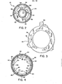
- Fig. 2 is an isolated view from above of the base structure of the assembly in the direction of the Arrow of Fig. 1
- Fig. 3 is an isolated top view of a cam ring employed in the base structure of Fig. 1 and seen in the direction of Arrow A and
- Fig. 4 is an isolated top view of the jaw elements employed in the assembly of Fig. 1 also seen in the direction of Arrow A of Fig. 1.
- Referring to Fig. 1, the
filter assembly 10 includes .a generallycylindrical cannister 12 which is closed at the upper end and open at the lower end, the lower end being provided with a rolledshoulder 14 for mounting over a generally cylindrical projectingpart 16 of a base structure to enclose areplaceable filter element 17 within the cannister. Thepart 16 includes a pair ofinlet passages inlet passage 20 is visible in the view of Fig. 1 which is provided in the drawing. Thepart 16 also includes anoutlet passage 22. Thesurface 23 of the projectingpart 16 co-operates with thefilter elements 17 so that oil flowing frominlets outlet 22 must pass through thefilter element 17. Furthermore, thepart 16 includes alarge diameter portion 24 separated from asmaller diameter portion 26 by aflange 28. Anannular groove 30 in theportion 24 provides for the retention of an 0-ring 32 which provides a.seal between the open end of thecannister 12 and thebase part 16. Six equally spacedradial bores 34 are provided for receiving press-fittedguide pins 36 which extends radially into thebase part 16. Threemounting bores 38 also extend axially to thebase part 16. Three equally spacedmounting bolts 40 are also provided as shown extending through themounting bores 38 to bolt thepart 16 to a supportingmember 42, themember 42 being suitably provided with tap threads for this purpose. - .
Support member 42 maybe either fixed to or a part of a vehicle engine block which is not shown and it is provided with a pair ofinlets 46 of which only one is visible in Fig. 1 but which communicates oil from the engine block to thefilter element 17 viainlet passages outlet passage 48 communicates oil from thefilter element 17 back to the engine block via thebase outlet passage 22.Filter element 17 is of generally known construction and such that fluid entering viainlets filter 17 in order to reach theoutlet 22. The supportingmember 42 also includes a pair ofannular slots ring seals support member 42 and thebase member 16.Support member 42 also includes a partially threaded axially bore 58 which houses a ball 60 urged upwardly by a spring 62 compressed by anadjustable screw 64. - In the locked position shown, the ball 60 engages with a
recess 74 to hold thering 70 locked against such movement as might occur as a result of vibration. Theannular cam ring 70 rests against the supportingmember 42 and is coaxially rotatable around thesmaller diameter portion 26 of thebase part 16. Six equally spacedoblong cam slots 72 extend axially through thecam ring 70 as clearly seen in Fig. 3 where theidentations tab 78 are also clearly visible. - Six
arcuate jaw elements 80 fit coaxially and end to end around thebase diameter 16, eachjaw element 80 including abase portion 82 with.an axial for 84 which receives a press fitted cam-pin 86. Thesecam pins 86 are slideably received by the above mentionedcam slots 72 of thecam ring 70. Eachjaw element 80 also includes anaxial bore 90 which slideably receives a corresponding one ofguide pins 36. A downward facingabutment surface 92 of each jaw element is provided to co-operate with theshoulder 14 of thecannister 12 to positively prevent the removal of thecannister 12 from the projectingpart 16 when thejaw elements 80 are in an inwardly , disposed position. - Although not regarded as an essential feature of the invention, a suitable bearing material such as "Teflon" maybe used as a coating on the sliding surfaces of 42, 16, 70 and
jaw elements 80. - In operation of the filter assembly as described above, the cannister is mounted to the assembly by pressing it downwards over the projecting
part 16 until theshoulder 14 thereof moves pass thesurfaces 92 on the underside of theengaging portion 88 of thejaw elements 80. Thecannister 12 may then be locked to the assembly by rotating thecam ring 70 by means of thetab 78 in a clock-wise direction viewed in the direction of para. A for Fig. 1. Such rotation of thecam ring 70 and co-operation ofcam pins 86 andcam slots 72 drives thepins 86 andjaw element 80 inwardly along therespective guide pins 36 into the locked position wherein theportions 88 ofjaw elements 80 come into radial compression against the outer surface of 12 thereby tending to create radial compression thereon'between the jaw elements and the projectingpart 16 carrying 0-ring seal 32. In such an inward locked position which is the position shown in Fig. 1 the shoulder-14 and theabutment surfaces 92 co-operate to prevent the move of thecannister 12 from thebase part 16. Also, in this position, the ball 60 is positively received by 74 which therefore constitutes a detent to prevent the cam ring inadvertently moving from the locked position. - When it is desired to replace the
filter element 17 , thecam ring 70 is rotated in an anti-clockwise direction viewed in the direction of the arrow A, to drive thecam pins 86 andjaw elements 80 radially outwards towards a position such as shown by draughtsmen licence on the right hand side of Fig. 1. In this position, thedetent 76 receives the ball 60 and the cam ring is held in a position whereby theportions 88 of thejaw elements 80 are sufficiently separated from the cylindrical cannister to permit the latter to be removed from thebase plant 16 and replacement of the filter element can thereby be achieved without the use of special tools to remove the cannister.
Claims (10)
1. A filter assembly with a replaceable filter element (17) in an open-ended filter cannister (12) the open end of which is slideable over and sealable with a projecting part (16) of a base structure of the assembly to enclose the filter element, characterised by the base structure carrying a plurality of jaw elements (80) spaced around the said part, said jaw elements being concommitantly laterally displaceable by a rotary member (70) adapted to effect a cam action in relation to said element and thereby enable them to retain or release the cannister.
2. A filter assembly as claimed in claim 1, characterised by the jaw element being provided with inward projecting portion (88) cooperable with an outward projection (14) of the cannister extending at least partially around the cannister in the vicinity of the open end thereof.
3. A filter assembly as claimed in claim 2, characterised by the outward projection (14) havinga shoulder and each jaw element (80) having a recess for receiving such a shoulder and an abutment surface (92) adjacent the recess the abutment surface and the shoulder cooperating to prevent removal of the cannister from the assembly when the jaws are in a locking position.
4. A filter assembly as claimed in claim 1, 2 or 3 characterised by the projecting part (16) being generally circular to receive a generally circular cannister and each of the jaw elements having a bore receiving a respective one of a plurality -of radical guide pins (36) carried by the said projecting part, the jaw elements also having cam engaging portions (86) 0040133 engaeable with cam surfaces (72) of the rotary actuator member (70) to provide for concommitant radial movement of the jaw elements (80).
5. A filter assembly as claimed in claim 4, characterised by the rotary member (70) being a generally annular platelike member.
6. A filter assembly as claimed in claim 5, characterised by the cam engaging portions (86) comprising projections extending from the jaws longitudinally in relation to the assembly to engage in respective cam-slots (72) in the actuator member.
7. A filter assembly as claimed in any preceeding claim characterised in that the projecting part (16) has an outer surface engageable with an inner surface of the cannister (12), the jaw elements (80) and the projecting parts (16 cooperating to hold the cannister there between under radial compression when the jaw elements (80) are in an inward and locked position.
8. A filter assembly as claimed in any of claims 1 to 7 characterised by the rotary member (70) having means (60, 62, 64, 74) for positively holding it in a locked position against inadvertent movement.
9. A filter assembly as claimed in claim 8 characterised by said means comprising a spring loaded member (60 and a recess (74).
10. A filter assembly substantially as described with reference to the accompanying Fig. 1 and Figs 2 to 4 of the drawings,
Applications Claiming Priority (2)
| Application Number | Priority Date | Filing Date | Title |
|---|---|---|---|
| US14797980A | 1980-05-08 | 1980-05-08 | |
| US147979 | 1980-05-08 |
Publications (2)
| Publication Number | Publication Date |
|---|---|
| EP0040133A2 true EP0040133A2 (en) | 1981-11-18 |
| EP0040133A3 EP0040133A3 (en) | 1982-04-21 |
Family
ID=22523718
Family Applications (1)
| Application Number | Title | Priority Date | Filing Date |
|---|---|---|---|
| EP81400692A Withdrawn EP0040133A3 (en) | 1980-05-08 | 1981-04-30 | Replaceable cartridge filter assembly |
Country Status (4)
| Country | Link |
|---|---|
| EP (1) | EP0040133A3 (en) |
| JP (1) | JPS574207A (en) |
| AU (1) | AU7006381A (en) |
| CA (1) | CA1164810A (en) |
Cited By (5)
| Publication number | Priority date | Publication date | Assignee | Title |
|---|---|---|---|---|
| EP0442365A2 (en) * | 1990-02-14 | 1991-08-21 | Stanadyne Automotive Corp. | Key system for filter assembly |
| USD492753S1 (en) | 2003-04-25 | 2004-07-06 | Procter & Gamble | Fluidic cartridge end piece |
| USD494654S1 (en) | 2003-04-25 | 2004-08-17 | Procter & Gamble Co. | Fluidic cartridge fittings |
| US10525387B2 (en) | 2017-04-06 | 2020-01-07 | Whirlpool Corporation | Filter cartridge |
| US10584040B2 (en) | 2017-10-06 | 2020-03-10 | Whirlpool Corporation | Filter cartridge |
Families Citing this family (1)
| Publication number | Priority date | Publication date | Assignee | Title |
|---|---|---|---|---|
| US4764275A (en) * | 1985-10-25 | 1988-08-16 | Robichaud Arthur W | Fluid filter and method for attaching same in sealing relation to a filter mount |
Citations (3)
| Publication number | Priority date | Publication date | Assignee | Title |
|---|---|---|---|---|
| DE939062C (en) * | 1952-10-01 | 1956-02-16 | Paul Forkardt K G | Front end chuck |
| US2780470A (en) * | 1953-12-01 | 1957-02-05 | Emi Ltd | Chucks |
| US3490594A (en) * | 1968-11-21 | 1970-01-20 | Fram Corp | Filter |
-
1981
- 1981-01-27 CA CA000369461A patent/CA1164810A/en not_active Expired
- 1981-04-30 EP EP81400692A patent/EP0040133A3/en not_active Withdrawn
- 1981-05-01 AU AU70063/81A patent/AU7006381A/en not_active Abandoned
- 1981-05-08 JP JP6841581A patent/JPS574207A/en active Pending
Patent Citations (3)
| Publication number | Priority date | Publication date | Assignee | Title |
|---|---|---|---|---|
| DE939062C (en) * | 1952-10-01 | 1956-02-16 | Paul Forkardt K G | Front end chuck |
| US2780470A (en) * | 1953-12-01 | 1957-02-05 | Emi Ltd | Chucks |
| US3490594A (en) * | 1968-11-21 | 1970-01-20 | Fram Corp | Filter |
Cited By (7)
| Publication number | Priority date | Publication date | Assignee | Title |
|---|---|---|---|---|
| EP0442365A2 (en) * | 1990-02-14 | 1991-08-21 | Stanadyne Automotive Corp. | Key system for filter assembly |
| EP0442365A3 (en) * | 1990-02-14 | 1991-10-23 | Stanadyne Automotive Corp. | Key system for filter assembly |
| USD492753S1 (en) | 2003-04-25 | 2004-07-06 | Procter & Gamble | Fluidic cartridge end piece |
| USD494654S1 (en) | 2003-04-25 | 2004-08-17 | Procter & Gamble Co. | Fluidic cartridge fittings |
| US10525387B2 (en) | 2017-04-06 | 2020-01-07 | Whirlpool Corporation | Filter cartridge |
| US10967313B2 (en) | 2017-04-06 | 2021-04-06 | Whirlpool Corporation | Filter cartridge |
| US10584040B2 (en) | 2017-10-06 | 2020-03-10 | Whirlpool Corporation | Filter cartridge |
Also Published As
| Publication number | Publication date |
|---|---|
| CA1164810A (en) | 1984-04-03 |
| AU7006381A (en) | 1981-11-12 |
| EP0040133A3 (en) | 1982-04-21 |
| JPS574207A (en) | 1982-01-09 |
Similar Documents
| Publication | Publication Date | Title |
|---|---|---|
| US4371439A (en) | Cam actuated filter assembly | |
| KR100710537B1 (en) | Filter cartridge and method and apparatus for replacing same | |
| EP0731739B1 (en) | Locking ring stripper plate assembly | |
| DE3347423A1 (en) | DEVICE FOR AUTOMATICALLY REPLACING AND COUPLING GRIPPERS ON ROBOTS OR HANDLING DEVICES | |
| EP0231500A2 (en) | Device for releasably mounting a disc-like working-tool | |
| EP0291482A1 (en) | Device for detachable and repeatable clamping of two objects to each other | |
| DE19901977C2 (en) | Clamping device for fixing a feed pin | |
| EP0040133A2 (en) | Replaceable cartridge filter assembly | |
| DE19600829A1 (en) | Drilling and chiseling device | |
| EP0401471A1 (en) | Intake air filter for combustion engines | |
| US7306111B2 (en) | Filter housing | |
| DE10002395B4 (en) | tensioning device | |
| EP1577054B1 (en) | Clamp cylinder with cover cap | |
| DE10013975A1 (en) | Adaptive workpiece tensioning and handling system has several structured clamping pallets with upper plate able to swivel about center axis and positioned in partial stages for different sized workpieces | |
| EP3043954A1 (en) | Clamping device for clamping at least one clamping nipple | |
| DE10360252A1 (en) | tool adapter | |
| US4258743A (en) | Expanding gate valve having mechanically secured seats | |
| EP0925872A2 (en) | Clamping device for fixing a clamping bolt to a carrier | |
| US4269221A (en) | Valve stem lock | |
| DE19806056A1 (en) | Modular brake with interchangeable brake pads | |
| SU1082524A1 (en) | Apparatus for securing quick-change tool | |
| US4204558A (en) | Valve assembly having remotely replaceable bearings | |
| DE3528443A1 (en) | COUPLING FOR DETACHABLE FASTENING OF A WORKPIECE CARRIER ON A RECEIVER FIXED TO A MACHINE TOOL | |
| WO1995014598A1 (en) | Drying cartridge for air drying installations, especially for vehicle air-brake systems | |
| EP0353384B1 (en) | Clamping device at machine tools with a circumferating clamping cylinder |
Legal Events
| Date | Code | Title | Description |
|---|---|---|---|
| PUAI | Public reference made under article 153(3) epc to a published international application that has entered the european phase |
Free format text: ORIGINAL CODE: 0009012 |
|
| 17P | Request for examination filed |
Effective date: 19810505 |
|
| AK | Designated contracting states |
Designated state(s): DE FR GB IT NL SE |
|
| PUAL | Search report despatched |
Free format text: ORIGINAL CODE: 0009013 |
|
| AK | Designated contracting states |
Designated state(s): DE FR GB IT NL SE |
|
| STAA | Information on the status of an ep patent application or granted ep patent |
Free format text: STATUS: THE APPLICATION IS DEEMED TO BE WITHDRAWN |
|
| 18D | Application deemed to be withdrawn |
Effective date: 19830128 |
|
| RIN1 | Information on inventor provided before grant (corrected) |
Inventor name: THORNTON, DONALD IRVING |