EP0040033A1 - Prism polarizer - Google Patents
Prism polarizer Download PDFInfo
- Publication number
- EP0040033A1 EP0040033A1 EP81301963A EP81301963A EP0040033A1 EP 0040033 A1 EP0040033 A1 EP 0040033A1 EP 81301963 A EP81301963 A EP 81301963A EP 81301963 A EP81301963 A EP 81301963A EP 0040033 A1 EP0040033 A1 EP 0040033A1
- Authority
- EP
- European Patent Office
- Prior art keywords
- prism
- prisms
- rays
- plane
- pair
- Prior art date
- Legal status (The legal status is an assumption and is not a legal conclusion. Google has not performed a legal analysis and makes no representation as to the accuracy of the status listed.)
- Granted
Links
Images


Classifications
-
- G—PHYSICS
- G02—OPTICS
- G02B—OPTICAL ELEMENTS, SYSTEMS OR APPARATUS
- G02B5/00—Optical elements other than lenses
- G02B5/04—Prisms
-
- G—PHYSICS
- G02—OPTICS
- G02B—OPTICAL ELEMENTS, SYSTEMS OR APPARATUS
- G02B27/00—Optical systems or apparatus not provided for by any of the groups G02B1/00 - G02B26/00, G02B30/00
- G02B27/28—Optical systems or apparatus not provided for by any of the groups G02B1/00 - G02B26/00, G02B30/00 for polarising
- G02B27/283—Optical systems or apparatus not provided for by any of the groups G02B1/00 - G02B26/00, G02B30/00 for polarising used for beam splitting or combining
-
- G—PHYSICS
- G02—OPTICS
- G02B—OPTICAL ELEMENTS, SYSTEMS OR APPARATUS
- G02B5/00—Optical elements other than lenses
- G02B5/30—Polarising elements
- G02B5/3025—Polarisers, i.e. arrangements capable of producing a definite output polarisation state from an unpolarised input state
- G02B5/3058—Polarisers, i.e. arrangements capable of producing a definite output polarisation state from an unpolarised input state comprising electrically conductive elements, e.g. wire grids, conductive particles
-
- G—PHYSICS
- G02—OPTICS
- G02B—OPTICAL ELEMENTS, SYSTEMS OR APPARATUS
- G02B5/00—Optical elements other than lenses
- G02B5/30—Polarising elements
- G02B5/3025—Polarisers, i.e. arrangements capable of producing a definite output polarisation state from an unpolarised input state
- G02B5/3066—Polarisers, i.e. arrangements capable of producing a definite output polarisation state from an unpolarised input state involving the reflection of light at a particular angle of incidence, e.g. Brewster's angle
-
- G—PHYSICS
- G02—OPTICS
- G02F—OPTICAL DEVICES OR ARRANGEMENTS FOR THE CONTROL OF LIGHT BY MODIFICATION OF THE OPTICAL PROPERTIES OF THE MEDIA OF THE ELEMENTS INVOLVED THEREIN; NON-LINEAR OPTICS; FREQUENCY-CHANGING OF LIGHT; OPTICAL LOGIC ELEMENTS; OPTICAL ANALOGUE/DIGITAL CONVERTERS
- G02F1/00—Devices or arrangements for the control of the intensity, colour, phase, polarisation or direction of light arriving from an independent light source, e.g. switching, gating or modulating; Non-linear optics
- G02F1/01—Devices or arrangements for the control of the intensity, colour, phase, polarisation or direction of light arriving from an independent light source, e.g. switching, gating or modulating; Non-linear optics for the control of the intensity, phase, polarisation or colour
- G02F1/09—Devices or arrangements for the control of the intensity, colour, phase, polarisation or direction of light arriving from an independent light source, e.g. switching, gating or modulating; Non-linear optics for the control of the intensity, phase, polarisation or colour based on magneto-optical elements, e.g. exhibiting Faraday effect
- G02F1/093—Devices or arrangements for the control of the intensity, colour, phase, polarisation or direction of light arriving from an independent light source, e.g. switching, gating or modulating; Non-linear optics for the control of the intensity, phase, polarisation or colour based on magneto-optical elements, e.g. exhibiting Faraday effect used as non-reciprocal devices, e.g. optical isolators, circulators
-
- G—PHYSICS
- G02—OPTICS
- G02F—OPTICAL DEVICES OR ARRANGEMENTS FOR THE CONTROL OF LIGHT BY MODIFICATION OF THE OPTICAL PROPERTIES OF THE MEDIA OF THE ELEMENTS INVOLVED THEREIN; NON-LINEAR OPTICS; FREQUENCY-CHANGING OF LIGHT; OPTICAL LOGIC ELEMENTS; OPTICAL ANALOGUE/DIGITAL CONVERTERS
- G02F2203/00—Function characteristic
- G02F2203/06—Polarisation independent
Definitions
- the present invention relates to an optical device, especially, it relates to a polarizer, comprising prisms, which is suitable for using in an optical switch or an optical circulator of small size.
- An optical circulator is one of such passive devices for use in the optical transmission system.
- the optical circulator has, for example, four ports for entrance and exit of a light beam.
- a beam introduced from a first port is transmitted to a second port.
- a beam introduced from the second port is transmitted to a third port.
- a beam introduced from the third port is transmitted to a fourth port.
- a beam introduced from the fourth port is transmitted to the first port.
- Four ports are optically interconnected so that a beam is cyclically transmitted in the above manner, i.e. 1 ⁇ 2 , 2 ⁇ 3, 3 ⁇ 4, 4 -7 1.
- such an optical circulator will make it possible to realize a complicated function such as two-way communication, impediment research, or data link, in an optical transmission system in the near future.
- Occurrence of transmission loss or crosstalk should be minimized in the optical circulator as well as in an optical switch or an optical branching filter.
- rays of light emitted from an inlet optical fiber are amended to be made parallel by means of a lens, so as to make a beam. Then, this beam is operated in a prescribed manner in the device. After that, the beam is converged to an ontlet optical fiber by another lens. However, a part of light leaks from the beam even though the rays of the beam are paralleled by the lens. Therefore, there is some transmission loss of light between the inlet fiber and the outlet fiber. Accordingly, it is desirable that the optical device is small in size so as to avoid the path length of light being elongated, from the view point of decreasing the transmission loss.
- a polarizer used in the optical circulator or the optical devices comprises two prisms of anisotropic crystals faced to each other.
- the prisms are usually made of calcite.
- An incident beam upon the facing plane is separated into two polarized beams, i.e. a beam of ordinary rays and a beam of extraordinary rays.
- the polarizations of the beams are perpendicular to each other.
- Examples of such a polarizer or a beam splitter of prior art are disclosed in Japanese Patent Publications 45-13278 and 52-49967 and Laid Open Japanese Patent A ppli- cation 49-93028,
- the size of the prism is large when compared with the diameter of the beam. Therefore, it is difficult to make the optical device comprising this polarizer to be small in size.
- the beam is not reliably separated in the polarizer of prior art. Therefore, when the polarizer is used in an optical circulator, excessive transmission loss and the problem of crosstalk occur.
- the present invention was made considering the above points.
- An object of the present invention is to provide a polarizer comprising prisms which is small in size and enables complete separation of the incident beam so that the transmission loss and the crosstalk are minimized,
- a prism polarizer comprises a pair of anisotropic crystal prisms which are faced to each other; said crystal prisms being composed of a crystal which has a refractive index for ordinary rays and another refractive index for extraordinary rays, the difference between the square of the refractive index for ordinary rays and the square of the refractive index for extraordinary rays being larger than 1; the P-polarization rays of the incident beam upon the facing plane of said pair of prisms being used as said ordinary rays and the angle of incidence being equal to the Brewster angle for said refractive index for said ordinary rays, so that P-polarization rays are transmitted through said facing plane while S-polarization rays are totally reflected at said facing plane, thereby separating the incident beam into two polarized beams; each of said prisms being formed so that each of said polarized beams is totally reflected within each prism and that the separated outlet beams from said prisms are parallel with each other.
- each of the prisms is arranged so that an entrance beam into the prism is slightly shifted from the direction perpendicular to an entrance end surface of the prism and that an exit beam out of the prism is slightly shifted from the direction perpendicular to an exit end surface of the prism.
- reference numerals 1 and 2 designate optical prisms of triangular prism shape and quadrilateral prism shape, respectively.
- Each prism is made of rutile (TiO 2 : titanium dioxide).
- the optical axis of each prism is perpendicular to the drawing.
- Reference numeral 3 designates a facing plane between the prisms 1 and 2.
- Such a gap is formed by disposing spacers such as thin wires of 10 p diameter between the two prisms which are combined with each other by an adequate means.
- the two prisms may be combined by means of an adherent agent which has an optical characteristic suitable for achieving the optical functions described later.
- the prism 1 has surfaces 4, 5, 11 for inner total reflection and entrance for optical beam.
- the prism 2 has surfaces 6 and 7 for inner total reflection and entrance for optical beam.
- the surface 4 of the prism 1 is inclined by an angle ⁇ with respect to the facing plane 3.
- the angle ⁇ is the Brewster angle for the P-polarization rays which pass through the surface of the prism from the inside to the outside thereof.
- the surface 6 of the prism 2 is also inclined by the Brewster angle 6 with respect to the facing plane 3.
- the titanium dioxide has two refractive indices n and n e for ordinary rays and extraordinary rays, respectively.
- the refractive index n 0 for ordinary rays is 2.46 at the wavelength of 1.3 pm.
- the refractive index n for extraordinary rays is 2.72 at the wavelength of 1.3 pm.
- the ordinary ray is a ray which polarization plane is perpendicular to the optic axis.
- the extraordinary ray is a ray which polarization plane is parallel to the optical axis.
- the optical axis of this titanium dioxide crystal is arranged so that P-polarization rays are transmitted as being ordinary rays while S-polarization rays are reflected as being extraordinary rays.
- the Brewster angle 0 is defined on the basis of the refractive index of n o for the ordinary rays as follows.
- An incident beam l introduced perpendicularly through the surface 6 of the prism 2 has an angle of incidence of ⁇ with respect to the facing plane 3.
- the surface 5 and the surface 7 are formed as being parallel to each other and perpendicular to the beams l T and l R which are emitted out of the prisms 1 and 2, respectively.
- the vertical angles A and B which define the surfaces 5 and 7 of the prisms 1 and 2 are 38 and 28, respectively.
- a beam of unpolarized light (natural light) l enters the prism 2 through the surface 6 perpendicularly to this surface 6.
- the angle of incidence of this beam l to the facing plane 3 is the Brewster angle ⁇ . Therefore, ordinary rays included within the unpolarized beam l completely pass through this facing plane 3.
- extraordinary rays included within the unpolarized beam l is totally reflected by this facing plane 3 since the extraordinary rays in the titanium dioxide meet the total reflection condition represented by the formula n sin ⁇ ⁇ 1.02 > 1.
- the natural light l is completely separated into two polarized beams, i.e. one is a beam l T of ordinary rays and the other is a beam l R of extraordinary rays.
- the polarizer of prior art comprising prisms of calcite
- Such defectiveness is completely obviated in the above mentioned polarizer of the present invention comprising prisms of titanium dioxide.
- any other anisotropic material can be. used instead of titanium dioxide if the optical characteristic of the material meets the following conditions with respect to the refractive index n o for ordinary rays, the refractive index n e for extraordinary rays, and the Brewster angle ⁇ for ordinary rays.
- the formula (1) represents the condition that the extraordinary rays are totally reflected at the boundary surface.
- the formula (2) represents the condition that the ordinary rays pass through the boundary surface.
- the formula (3) is derived from the formulas (1) and (2): Therefore, a beam of rays which meets the formula (3) is completely separated into a beam of ordinary rays and another beam of extraordinary rays.
- the value of n e 2 - n o 2 is approximately, 1.35 at the wavelength of 1.3 ⁇ . Therefore, the titanium dioxide meets the condition of formula (3).
- the formula (1) is rewritten to n sine > n
- the formula (3) is rewritten to 2 e 2 2 n e - n o > n .
- the incident beam l (solid line) is completely separated into a polarized beam l T (dotted line) of ordinary rays and another polarized beam l R (a dash-dot line) of extraordinary rays.
- the beam l T of ordinary rays enters into the prism 1 through the gap existing on the facing plane 3, in the same direction of the incident beam l .
- Actual pass of the beam l T is shown in Fig. 3.
- the beam l T is refracted at the boundary surface 9 between the prism 2 and the gap 8, and then refracted again at the boundary surface 10 between the prism 1 and the gap 8.
- the beam l T is refracted in the reverse direction to the refraction direction at the first refraction.
- the second refraction angle is equal to the B rewster angle e as illustrated in Fig. 3. Therefore, the beam l T of ordinary rays in the prism 1 is in parallel to the incident beam l.
- the distance x between the beams i and l T is represented as follows. in which t is depth of the gap 8.
- the beam l T of ordinary rays passes through the prism 1 while the beam l R of extraordinary rays passes through the prism 2.
- the beams l T and l R are totally reflected twice within the respective prisms 1 and 2 as follows.
- the beam l T of ordinary rays included within the incident beam l is totally reflected at the surface 4 and the surface 11 which is substancially the same as the facing plane 3.
- the beam l R of extraordinary rays is totally reflected at the facing plane 3 and the surface 6.
- the two beams l T and l R are symmetrically separated with respect to the facing plane 3 and reflected at the surfaces 4 and 6 which are inclined by the same angle of ⁇ with respect to the facing plane 3.
- the two beams i and l R are paralleled by being totally reflected twice within the respective prisms.
- the paralleled beams l T and l R pass through the end surfaces 5 and 7, out of the prisms 1 and 2, respectively.
- the exit beams l T and l R are perpendicular to the end surfaces 5 and 7, respectively.
- the two separated beams of ordinary rays and extraordinary rays are paralleled without using further optical devices. Therefore, an optical circulator of small size and comprising small number of parts can be realized by using the polarizer of the present invention, as described later.
- each beam within each prism is illustrated so as to show that the polarizer is small with respect to the beam width, i.e., almost whole portion of prisms is actually used as the pass of beam and the exit beams are close to each other.
- each prism is effectively used as the pass of beam of width w. Also, it can be seen that the paralleled exit beams are closed to each other.
- This optical circulator includes a first polarizer 15 which comprises a pair of prisms 11, 12 and a second polarizer 16 which comprises a pair of prisms 13, 14.
- a rotatory polarization device 17 is disposed between the first and the second polarizer 15, 16.
- the rotatory polarization device 17 is illustrated in F ig. 8.
- the device 17 comprises a Faraday rotator 21 for 45° rotation of polarization plane and a rotatory polarization plate 20 of such as a half wave plate.
- the Faraday rotator 21 comprises a permanent magnet ring 18 for generating a magnetic field and a transparent magnetic piece 19 of YIG (Y 3 Fe 5 O 12 ) crystal.
- YIG Y 3 Fe 5 O 12
- the rotational direction of the Faraday rotator 21 and the rotatory polarization plate 20 are opposite to each other for the beam from the left to the right in the drawing, while the rotational directions are the same for the beam from the right to the left.
- the thickness and the position of the magnetic piece 19 or the rotatory polarization plate 20 are determined so that they achieve the above mentioned functions.
- the polarization plane of a beam (a) from the left is rotated by 45° by the Faraday rotator 21 in one direction and then rotated by 45° by the rotatory polarization plate 20 in the reverse direction so that the polarization plane restores to the original position, i.e. the polarization plane is unchanged by the rotatory polarization device 17.
- the polarization plane of a beam (b) from the right is rotated by 45° by the rotatory polarization plate 20 in one direction and then rotated again by 45° by the Faraday rotator 21 in the same direction so that the polarization plane is rotated by 90° in total. Therefore, an ordinary ray from the right is changed to an extraordinary ray. Similarly, an extraordinary ray from the right is changed to an ordinary ray.
- a first port P 1 (Fig. 4 and Fig. 7) is provided for entrance and exit for the beam into and out of the prism 11 of the first polarizer 15.
- a second port P 2 (Figs. 4 and 5), a third port P 3 (Figs. 5 and 6) and a fourth port P 4 (Figs. 6, 7) are provided at the positions facing to the prisms 13, 12, 14, respectively.
- this optical circulator for the beam introduced from the first port P 1 is shown in Fig. 4.
- a natural optical beam from the first port P 1 is completely separated into an ordinary beam i T and an extraordinary beam l R in a manner described before at the facing plane of the prisms 11 and 12 of the first polarizer 15.
- the rotatory polarization device 17 is arranged so that the polarization planes of these beams from the left side in the drawing are not rotated as mentioned before. Therefore, the ordinary beam l T and the extraordinary beam l R are unchanged by the rotatory polarization device 17 and introduced into the second polarizer 16 as being the ordinary beam and the extraordinary beam, respectively.
- the extraordinary beam l R is totally reflected, while the ordinary beam l T is transmitted through this plane 3. Therefore, the two beams l T and l R are combined within the prism 13 and transmitted out R of the prism 13 through the second port P 2 .
- the path of a nataral beam from the second port P 2 is illustrated in Fig. 5.
- the beam is separated into an ordinary beam l T and an extraordinary beam l R and pass through the rotatory polarization device 17.
- the polarization plane of the beam from the right side in the drawing is rotated by 90° by the rotatory polarization device 17. Therefore, the ordinary beam l T is changed to an extraordinary beam l R' , while the extraordinary beam l R is changed to an ordinary beam l T' .
- Each of the beams l R' and l T is introduced into the first polarizer 15.
- the extraordinary beam l R' is totally reflected, while the ordinary beam l T' is transmitted through this plane 3. Therefore, the two beams l R' and l T' are combined together within the prism 12 and transmitted out of the prism 12 through the third port P 3 .
- the path of a natural beam from the third port P 3 is illustrated in Fig. 6.
- the beam from the third port P 3 is transmitted to the fourth port P 4 in the similar manner as the manner of the bear from the first port P l .
- the path of a natural beam from the fourth port P 4 is illustrated in Fig. 7.
- the beam from the fourth port P 4 is transmitted to the port P 1 in the similar manner as the manner of the beam from the second port P 2 .
- the incident beam upon the facing plane of the pair of prisms of the polarizer is completely separated into an ordinary beam and an extraordinary beam due to the optical characteristic of this polarizer. Also, the separeted two beams are completely combined together in the other polarization due to the optical characteristic of this polarizer. Therefore, the occurrence of the transmission loss and the crosstalk is minimized.
- the separated ordinary beam l T and the extraordinary beam t R is pralleled and close to each other. Therefore, one common rotatory polarization device 17 can be used for the two beams instead of providing one device for every one beam.
- one common rotatory polarization device cannot be used by the reason set forth below. If the two beams are not parallel to each other, the direction of at least one beam does not align with the direction of the magnetic field of the Faraday rotator. In such a condition, a linearly polarized ray (a completely polarized ray) is changed to an elliptically poralized ray Jan incompletely polarized ray) instead of being changed to a linearly polarized ray, after the rotation of the polarization plane by the rotatory polarization device. Therefore, the homogeneity of each of the separated beams is degraded by passing through the rotatory polarization device. Accordingly, it is necessary to apply one rotatory polarization device for every one beam, if the separated beams are not parallel.
- a mirror or other optical devices for paralleling the separated beams are not necessary since the separated ordinary beam and the extraordinary beam are parallel to each other.
- the transmission loss within the above mentioned another prism, a mirror or other optical devices is avoided. Therefore, the optical loss is decreased and the manufacturing cost can be lowered since the number of parts is decreased and the optical path length can be shortened.
- the shape of the prism of the polarizer according to the present invention is not limited to the shape illustrated in Fig. 1, but can be modified into various shapes. Modified examples are illustrated in Figs. 9 through 12. One of a pair of prisms of the polarizer is illustrated in each drawing. Reference numeral 3 designates the facing plane of the pair of prisms of the polarizer. Any two of the prisms illustrated in Figs. 9 through 12, i.e. either different two or same two prisms out of the four prisms, can be combined to make a pair of prisms of the polarizer.
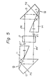
- FIG. 13 An optical circulator comprising prisms of Fig. 9 is illustrated in Fig. 13.
- an optical beam is transmitted from the second port P 2 to the third port P 3 .
- Such a condition corresponds to the condition of Fig. 5.
- Combination of prisms of different shape is possible instead of the combination of prisms of same shape as illustrated in Fig. 13.
- the shape of the prisms should be changed corresponding to the change of the refractive index.
- a common feature of these prisms is that the outlet beam from each prism can be paralleled to the facing plane 3.
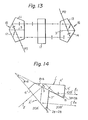
- FIG. 14 Another embodiment of the prism polarizer according to the present invention is illustrated in Fig. 14.
- an inlet end surface and an outlet end surface of each prism are slightly inclined with respect to the planes perpendicular to the inlet beam and the outlet beam, respectively. Therefore, the reflected light at the inlet or outlet end surface does not go back in the same path.
- the inclined angle is within the range of +1° ⁇ +6° or -1° ⁇ -6° so that the aforementioned function of the prism can be maintained.
- the surface 4' of the prism 1' is inclined by an angle of ⁇ + ⁇ with respect to the facing plane 3.
- the surface 6' of the prism 2' is inclinced by the angle of 6+6 with respect to the facing plane 3.
- 6 is the Brewster angle and ⁇ is a small inclination angle.
- the surface 5' of the prism 1' is inclined-by the angle of 3 ⁇ +3 ⁇ .
- the surface 7' of the prism 2' is inclined by the angle of 26+26 with respect to the surface 6'.
- the angle of incidence of the inlet beam l upon the facing plane 3 is maintained to be the Brewster angle 8 for ordinary rays.
- the inlet beam l is not perpendicular to the surface 6' of the prism 2'.
- the separated ordinary beam l T and extraordinary beam l R are not perpendicular to the surface 5' of the prism 1' and the surface 7' of the prism 2', respectively.
- the reflected light at the inlet end surface 6' or the outlet end surface 5' or 7' does not go back in the same path since the path is not perpendicular to each end surface. Consequently, adverse effect upon a laser source can be avoided.
- the absolute value of the small inclination angle ⁇ is below 2° so that the difference of refraction angle of the ordinary beam and the extraordinary beam at each end surface can be maintained small enough for ensuring a reliable communication between the beam and an optical fiber at each port.
Abstract
Description
- The present invention relates to an optical device, especially, it relates to a polarizer, comprising prisms, which is suitable for using in an optical switch or an optical circulator of small size.
- Various improved passive optical devices have been utilized in the optical transmission system of today.
- An optical circulator is one of such passive devices for use in the optical transmission system. The optical circulator has, for example, four ports for entrance and exit of a light beam. A beam introduced from a first port is transmitted to a second port. A beam introduced from the second port is transmitted to a third port. A beam introduced from the third port is transmitted to a fourth port. A beam introduced from the fourth port is transmitted to the first port. Four ports are optically interconnected so that a beam is cyclically transmitted in the above manner, i.e. 1 → 2 , 2 → 3, 3 → 4, 4 -7 1. such an optical circulator will make it possible to realize a complicated function such as two-way communication, impediment research, or data link, in an optical transmission system in the near future.
- Occurrence of transmission loss or crosstalk should be minimized in the optical circulator as well as in an optical switch or an optical branching filter. In order to obviate the transmission loss and the crosstalk, rays of light emitted from an inlet optical fiber are amended to be made parallel by means of a lens, so as to make a beam. Then, this beam is operated in a prescribed manner in the device. After that, the beam is converged to an ontlet optical fiber by another lens. However, a part of light leaks from the beam even though the rays of the beam are paralleled by the lens. Therefore, there is some transmission loss of light between the inlet fiber and the outlet fiber. Accordingly, it is desirable that the optical device is small in size so as to avoid the path length of light being elongated, from the view point of decreasing the transmission loss.
- In general, a polarizer used in the optical circulator or the optical devices comprises two prisms of anisotropic crystals faced to each other. The prisms are usually made of calcite. An incident beam upon the facing plane is separated into two polarized beams, i.e. a beam of ordinary rays and a beam of extraordinary rays. The polarizations of the beams are perpendicular to each other.
- Examples of such a polarizer or a beam splitter of prior art are disclosed in Japanese Patent Publications 45-13278 and 52-49967 and Laid Open Japanese Patent Appli- cation 49-93028, In the polarizer of prior art, the size of the prism is large when compared with the diameter of the beam. Therefore, it is difficult to make the optical device comprising this polarizer to be small in size. Besides, the beam is not reliably separated in the polarizer of prior art. Therefore, when the polarizer is used in an optical circulator, excessive transmission loss and the problem of crosstalk occur.
- The present invention was made considering the above points.
- An object of the present invention is to provide a polarizer comprising prisms which is small in size and enables complete separation of the incident beam so that the transmission loss and the crosstalk are minimized,
- A prism polarizer according to the present invention comprises a pair of anisotropic crystal prisms which are faced to each other; said crystal prisms being composed of a crystal which has a refractive index for ordinary rays and another refractive index for extraordinary rays, the difference between the square of the refractive index for ordinary rays and the square of the refractive index for extraordinary rays being larger than 1; the P-polarization rays of the incident beam upon the facing plane of said pair of prisms being used as said ordinary rays and the angle of incidence being equal to the Brewster angle for said refractive index for said ordinary rays, so that P-polarization rays are transmitted through said facing plane while S-polarization rays are totally reflected at said facing plane, thereby separating the incident beam into two polarized beams; each of said prisms being formed so that each of said polarized beams is totally reflected within each prism and that the separated outlet beams from said prisms are parallel with each other.
- In a preferred embodiment of the present invention, each of the prisms is arranged so that an entrance beam into the prism is slightly shifted from the direction perpendicular to an entrance end surface of the prism and that an exit beam out of the prism is slightly shifted from the direction perpendicular to an exit end surface of the prism.
- Embodiments of the present invention will be described hereinafter with reference to the accompanying drawings.
-
- Fig. 1 is a view showing an example of a prism polarizer according to the present invention.
- Fig. 2 is a view showing a relation between the width of an optical beam and the size of the prism of Fig. 1.
- Fig. 3 is a detailed view of facing surfaces of a pair of prisms according to the present invention.
- Figs. 4 through 7 are views showing different operation, respectively, of an optical circulator using a prism polarizer according to the present invention.
- Fig. 8 is a detailed view of a rotatory polarization device used in the optical circulator of Figs. 4 through 7.
- Figs. 9 through 12 are views showing different embodiments of the present invention, respectively.
- Fig. 13 is a view of an optical circulator using the prism polarizer of Fig. 9.
- Fig. 14 is a view of another embodiment of the present invention.
- In Fig. 1, reference numerals 1 and 2 designate optical prisms of triangular prism shape and quadrilateral prism shape, respectively. Each prism is made of rutile (TiO2: titanium dioxide). The optical axis of each prism is perpendicular to the drawing.
Reference numeral 3 designates a facing plane between the prisms 1 and 2. In fact, there is a very thin gap of about 10 µ between the prisms 1 and 2 so that a thin layer of air is formed therebetween. Such a gap is formed by disposing spacers such as thin wires of 10 p diameter between the two prisms which are combined with each other by an adequate means. Instead of forming such a gap of layer of air, the two prisms may be combined by means of an adherent agent which has an optical characteristic suitable for achieving the optical functions described later. - The prism 1 has
surfaces surfaces - The configurations of these prisms are as follows.
- The
surface 4 of the prism 1 is inclined by an angle θ with respect to the facingplane 3. The angle θ is the Brewster angle for the P-polarization rays which pass through the surface of the prism from the inside to the outside thereof. Thesurface 6 of the prism 2 is also inclined by theBrewster angle 6 with respect to the facingplane 3. The titanium dioxide has two refractive indices n and ne for ordinary rays and extraordinary rays, respectively. The refractive index n0 for ordinary rays is 2.46 at the wavelength of 1.3 pm. The refractive index n for extraordinary rays is 2.72 at the wavelength of 1.3 pm. The ordinary ray is a ray which polarization plane is perpendicular to the optic axis. The extraordinary ray is a ray which polarization plane is parallel to the optical axis. The optical axis of this titanium dioxide crystal is arranged so that P-polarization rays are transmitted as being ordinary rays while S-polarization rays are reflected as being extraordinary rays. - The Brewster angle 0 is defined on the basis of the refractive index of n o for the ordinary rays as follows.
- An incident beam ℓ introduced perpendicularly through the
surface 6 of the prism 2 has an angle of incidence of θ with respect to the facingplane 3. Thesurface 5 and thesurface 7 are formed as being parallel to each other and perpendicular to the beams ℓT and ℓR which are emitted out of the prisms 1 and 2, respectively. In this example, the vertical angles A and B which define thesurfaces - Above described assembly of prisms 1 and 2 operates as follows.
- A beam of unpolarized light (natural light) ℓ enters the prism 2 through the
surface 6 perpendicularly to thissurface 6. The angle of incidence of this beam ℓ to the facingplane 3 is the Brewster angle θ. Therefore, ordinary rays included within the unpolarized beam ℓ completely pass through this facingplane 3. On the other hand, extraordinary rays included within the unpolarized beam ℓ, is totally reflected by this facingplane 3 since the extraordinary rays in the titanium dioxide meet the total reflection condition represented by the formula n sinθ ≒ 1.02 > 1. - Accordingly, the natural light ℓ, is completely separated into two polarized beams, i.e. one is a beam ℓT of ordinary rays and the other is a beam ℓR of extraordinary rays. In the polarizer of prior art comprising prisms of calcite, there is a defective point that a part of the polarized rays is reflected at the facing plane which rays are to be transmitted through the facing plane instead of being reflected. Such defectiveness is completely obviated in the above mentioned polarizer of the present invention comprising prisms of titanium dioxide.
- Any other anisotropic material can be. used instead of titanium dioxide if the optical characteristic of the material meets the following conditions with respect to the refractive index no for ordinary rays, the refractive index n e for extraordinary rays, and the Brewster angle θ for ordinary rays.


- The formula (1) represents the condition that the extraordinary rays are totally reflected at the boundary surface. The formula (2) represents the condition that the ordinary rays pass through the boundary surface. The formula (3) is derived from the formulas (1) and (2): Therefore, a beam of rays which meets the formula (3) is completely separated into a beam of ordinary rays and another beam of extraordinary rays. In the case that titanium dioxide is used, the value of n e 2 - no 2 is approximately, 1.35 at the wavelength of 1.3 µ. Therefore, the titanium dioxide meets the condition of formula (3).
- If the pair of prisms are combined by an adhesive agent of refraction index of n instead of forming a gap of air between the prisms, the formula (1) is rewritten to n sine > n, and the formula (3) is rewritten to 2 e 2 2 ne - no > n .
- In Fig. 1, the incident beam ℓ (solid line) is completely separated into a polarized beam ℓT (dotted line) of ordinary rays and another polarized beam ℓR (a dash-dot line) of extraordinary rays. The beam ℓT of ordinary rays enters into the prism 1 through the gap existing on the facing
plane 3, in the same direction of the incident beam ℓ . Actual pass of the beam ℓT is shown in Fig. 3. The beam ℓT is refracted at the boundary surface 9 between the prism 2 and thegap 8, and then refracted again at theboundary surface 10 between the prism 1 and thegap 8. At the second refraction, the beam ℓT is refracted in the reverse direction to the refraction direction at the first refraction. The second refraction angle is equal to the Brewster angle e as illustrated in Fig. 3. Therefore, the beam ℓT of ordinary rays in the prism 1 is in parallel to the incident beam ℓ. The distance x between the beams i and ℓT is represented as follows.
gap 8. - In an example, x = 19 µ provided that the Brewster angle θ = 22.1° and t = 1.0 µ. Such a distance x can be neglected.
- The beam ℓT of ordinary rays passes through the prism 1 while the beam ℓR of extraordinary rays passes through the prism 2. The beams ℓT and ℓR are totally reflected twice within the respective prisms 1 and 2 as follows. The beam ℓT of ordinary rays included within the incident beam ℓ is totally reflected at the
surface 4 and the surface 11 which is substancially the same as the facingplane 3. The beam ℓR of extraordinary rays is totally reflected at the facingplane 3 and thesurface 6. The two beams ℓT and ℓR are symmetrically separated with respect to the facingplane 3 and reflected at thesurfaces plane 3. Therefore, the two beams i and ℓR are paralleled by being totally reflected twice within the respective prisms. The paralleled beams ℓT and ℓR pass through the end surfaces 5 and 7, out of the prisms 1 and 2, respectively. The exit beams ℓT and ℓR are perpendicular to the end surfaces 5 and 7, respectively. - In the polarizer according to the present invention, the two separated beams of ordinary rays and extraordinary rays are paralleled without using further optical devices. Therefore, an optical circulator of small size and comprising small number of parts can be realized by using the polarizer of the present invention, as described later.
- In Fig. 2, the width of each beam within each prism is illustrated so as to show that the polarizer is small with respect to the beam width, i.e., almost whole portion of prisms is actually used as the pass of beam and the exit beams are close to each other.
- Vertical angles of the prisms are as follows.


- As can be seen from the drawing, the inner portion of each prism is effectively used as the pass of beam of width w. Also, it can be seen that the paralleled exit beams are closed to each other.
- An optical circulator using the above mentioned polarizer of the present invention is illustrated in Figs. 4 through 7. This optical circulator includes a
first polarizer 15 which comprises a pair ofprisms 11, 12 and asecond polarizer 16 which comprises a pair ofprisms rotatory polarization device 17 is disposed between the first and thesecond polarizer - The
rotatory polarization device 17 is illustrated in Fig. 8. Thedevice 17 comprises aFaraday rotator 21 for 45° rotation of polarization plane and arotatory polarization plate 20 of such as a half wave plate. TheFaraday rotator 21 comprises apermanent magnet ring 18 for generating a magnetic field and a transparentmagnetic piece 19 of YIG (Y3Fe5O12) crystal. Each of theFaraday rotator 21 and therotatory polarization plate 20 rotates by 45° of the polarization plane of an optical beam which passes therethrough. The rotational direction of theFaraday rotator 21 and therotatory polarization plate 20 are opposite to each other for the beam from the left to the right in the drawing, while the rotational directions are the same for the beam from the right to the left. The thickness and the position of themagnetic piece 19 or therotatory polarization plate 20 are determined so that they achieve the above mentioned functions. The polarization plane of a beam (a) from the left is rotated by 45° by theFaraday rotator 21 in one direction and then rotated by 45° by therotatory polarization plate 20 in the reverse direction so that the polarization plane restores to the original position, i.e. the polarization plane is unchanged by therotatory polarization device 17. Therefore, if an ordinary ray is introduced from the left into thedevice 17, the ray exits out of the device as being the ordinary ray. Similarly, if an extraordinary ray is introduced from the left into thedevice 17, the ray exits out of the device as being the extraordinary ray. - On the other hand, the polarization plane of a beam (b) from the right is rotated by 45° by the
rotatory polarization plate 20 in one direction and then rotated again by 45° by theFaraday rotator 21 in the same direction so that the polarization plane is rotated by 90° in total. Therefore, an ordinary ray from the right is changed to an extraordinary ray. Similarly, an extraordinary ray from the right is changed to an ordinary ray. - A first port P1 (Fig. 4 and Fig. 7) is provided for entrance and exit for the beam into and out of the prism 11 of the
first polarizer 15. Similarly, a second port P2 (Figs. 4 and 5), a third port P3 (Figs. 5 and 6) and a fourth port P 4 (Figs. 6, 7) are provided at the positions facing to theprisms - The function of this optical circulator for the beam introduced from the first port P1 is shown in Fig. 4. A natural optical beam from the first port P1 is completely separated into an ordinary beam iT and an extraordinary beam ℓR in a manner described before at the facing plane of the
prisms 11 and 12 of thefirst polarizer 15. Therotatory polarization device 17 is arranged so that the polarization planes of these beams from the left side in the drawing are not rotated as mentioned before. Therefore, the ordinary beam ℓT and the extraordinary beam ℓR are unchanged by therotatory polarization device 17 and introduced into thesecond polarizer 16 as being the ordinary beam and the extraordinary beam, respectively. At the facingplane 3 of theprisms second polarizer 16, the extraordinary beam ℓR is totally reflected, while the ordinary beam ℓT is transmitted through thisplane 3. Therefore, the two beams ℓT and ℓR are combined within theprism 13 and transmitted out R of theprism 13 through the second port P2. - The path of a nataral beam from the second port P2 is illustrated in Fig. 5. The beam is separated into an ordinary beam ℓT and an extraordinary beam ℓR and pass through the
rotatory polarization device 17. As mentioned before, the polarization plane of the beam from the right side in the drawing is rotated by 90° by therotatory polarization device 17. Therefore, the ordinary beam ℓT is changed to an extraordinary beam ℓR' , while the extraordinary beam ℓR is changed to an ordinary beam ℓT'. Each of the beams ℓR' and ℓT, is introduced into thefirst polarizer 15. At the facingplane 3 of theprisms 11, 12 of thisfirst polarizer 15, the extraordinary beam ℓR' is totally reflected, while the ordinary beam ℓT' is transmitted through thisplane 3. Therefore, the two beams ℓR' and ℓT' are combined together within theprism 12 and transmitted out of theprism 12 through the third port P3. - The path of a natural beam from the third port P3 is illustrated in Fig. 6. The beam from the third port P3 is transmitted to the fourth port P4 in the similar manner as the manner of the bear from the first port Pl.
- The path of a natural beam from the fourth port P4 is illustrated in Fig. 7. The beam from the fourth port P4 is transmitted to theport P1 in the similar manner as the manner of the beam from the second port P2.

- In the above mentionned optical circulator, the incident beam upon the facing plane of the pair of prisms of the polarizer is completely separated into an ordinary beam and an extraordinary beam due to the optical characteristic of this polarizer. Also, the separeted two beams are completely combined together in the other polarization due to the optical characteristic of this polarizer. Therefore, the occurrence of the transmission loss and the crosstalk is minimized.
- The separated ordinary beam ℓT and the extraordinary beam tR is pralleled and close to each other. Therefore, one common
rotatory polarization device 17 can be used for the two beams instead of providing one device for every one beam. - If the two beams are not parallel to each other, one common rotatory polarization device cannot be used by the reason set forth below. If the two beams are not parallel to each other, the direction of at least one beam does not align with the direction of the magnetic field of the Faraday rotator. In such a condition, a linearly polarized ray (a completely polarized ray) is changed to an elliptically poralized ray Jan incompletely polarized ray) instead of being changed to a linearly polarized ray, after the rotation of the polarization plane by the rotatory polarization device. Therefore, the homogeneity of each of the separated beams is degraded by passing through the rotatory polarization device. Accordingly, it is necessary to apply one rotatory polarization device for every one beam, if the separated beams are not parallel.
- Also, in the optical circulator illustrated in Figs. 4 through 7, another prism, a mirror or other optical devices for paralleling the separated beams are not necessary since the separated ordinary beam and the extraordinary beam are parallel to each other. The transmission loss within the above mentioned another prism, a mirror or other optical devices is avoided. Therefore, the optical loss is decreased and the manufacturing cost can be lowered since the number of parts is decreased and the optical path length can be shortened.
- The shape of the prism of the polarizer according to the present invention is not limited to the shape illustrated in Fig. 1, but can be modified into various shapes. Modified examples are illustrated in Figs. 9 through 12. One of a pair of prisms of the polarizer is illustrated in each drawing.
Reference numeral 3 designates the facing plane of the pair of prisms of the polarizer. Any two of the prisms illustrated in Figs. 9 through 12, i.e. either different two or same two prisms out of the four prisms, can be combined to make a pair of prisms of the polarizer. - An optical circulator comprising prisms of Fig. 9 is illustrated in Fig. 13. In Fig. 13, an optical beam is transmitted from the second port P2 to the third port P3. Such a condition corresponds to the condition of Fig. 5. Combination of prisms of different shape is possible instead of the combination of prisms of same shape as illustrated in Fig. 13.
- Actual value of each vertical angle of each prism is as follows. The value is determined to meet the condition that the outlet beam is parallel with the facing
plane 3.


- If the refractive index changes in accordance with the wavelength of the beam, the shape of the prisms should be changed corresponding to the change of the refractive index.
- A common feature of these prisms is that the outlet beam from each prism can be paralleled to the facing
plane 3. - Another embodiment of the prism polarizer according to the present invention is illustrated in Fig. 14. In this embodiment, an inlet end surface and an outlet end surface of each prism are slightly inclined with respect to the planes perpendicular to the inlet beam and the outlet beam, respectively. Therefore, the reflected light at the inlet or outlet end surface does not go back in the same path. The inclined angle is within the range of +1°~ +6° or -1° ~ -6° so that the aforementioned function of the prism can be maintained.
- As illustrated in Fig. 14, the surface 4' of the prism 1' is inclined by an angle of θ+δ with respect to the facing
plane 3. Also, the surface 6' of the prism 2' is inclinced by the angle of 6+6 with respect to the facingplane 3. 6 is the Brewster angle and δ is a small inclination angle. The surface 5' of the prism 1' is inclined-by the angle of 3θ+3δ. The surface 7' of the prism 2' is inclined by the angle of 26+26 with respect to the surface 6'. The angle of incidence of the inlet beam ℓ upon the facingplane 3 is maintained to be theBrewster angle 8 for ordinary rays. The inlet beam ℓ is not perpendicular to the surface 6' of the prism 2'. The separated ordinary beam ℓT and extraordinary beam ℓR are not perpendicular to the surface 5' of the prism 1' and the surface 7' of the prism 2', respectively. - The reflected light at the inlet end surface 6' or the outlet end surface 5' or 7' does not go back in the same path since the path is not perpendicular to each end surface. Consequently, adverse effect upon a laser source can be avoided. The absolute value of the small inclination angle δ is below 2° so that the difference of refraction angle of the ordinary beam and the extraordinary beam at each end surface can be maintained small enough for ensuring a reliable communication between the beam and an optical fiber at each port.
Claims (10)
Applications Claiming Priority (2)
| Application Number | Priority Date | Filing Date | Title |
|---|---|---|---|
| JP1980063659U JPS6118481Y2 (en) | 1980-05-09 | 1980-05-09 | |
| JP63659/80U | 1980-05-09 |
Publications (2)
| Publication Number | Publication Date |
|---|---|
| EP0040033A1 true EP0040033A1 (en) | 1981-11-18 |
| EP0040033B1 EP0040033B1 (en) | 1987-11-25 |
Family
ID=13235689
Family Applications (1)
| Application Number | Title | Priority Date | Filing Date |
|---|---|---|---|
| EP81301963A Expired EP0040033B1 (en) | 1980-05-09 | 1981-05-05 | Prism polarizer |
Country Status (5)
| Country | Link |
|---|---|
| US (1) | US4392722A (en) |
| EP (1) | EP0040033B1 (en) |
| JP (1) | JPS6118481Y2 (en) |
| CA (1) | CA1160490A (en) |
| DE (1) | DE3176546D1 (en) |
Cited By (6)
| Publication number | Priority date | Publication date | Assignee | Title |
|---|---|---|---|---|
| EP0112187A2 (en) * | 1982-12-21 | 1984-06-27 | Crosfield Electronics Limited | Light-beam splitter |
| EP0376395A2 (en) * | 1988-12-27 | 1990-07-04 | Koninklijke Philips Electronics N.V. | Illumination system for an LCD display system |
| FR2654844A1 (en) * | 1989-11-21 | 1991-05-24 | Scanera Sc Ste Civile Rech | Light-polarisation device |
| EP0457605A2 (en) * | 1990-05-18 | 1991-11-21 | Canon Kabushiki Kaisha | Polarization converting device and polarized-light illuminating system using the device and image display unit using the device |
| EP0474237A1 (en) * | 1990-09-06 | 1992-03-11 | Seiko Epson Corporation | Prism optical device and polarizer using it |
| CN100456080C (en) * | 2006-12-01 | 2009-01-28 | 上海微电子装备有限公司 | Constant-offset collimated output beam splitter |
Families Citing this family (14)
| Publication number | Priority date | Publication date | Assignee | Title |
|---|---|---|---|---|
| US4464022A (en) * | 1982-09-28 | 1984-08-07 | At&T Bell Laboratories | Optical circulator |
| JPS59127019A (en) * | 1983-01-11 | 1984-07-21 | Canon Inc | Printer head |
| US4638470A (en) * | 1984-05-09 | 1987-01-20 | Xerox Corporation | Apparatus using beam splitter cube with specific characteristics for reading information recorded in a magneto-optic medium |
| US4681450A (en) * | 1985-06-21 | 1987-07-21 | Research Corporation | Photodetector arrangement for measuring the state of polarization of light |
| US4822150A (en) * | 1987-05-18 | 1989-04-18 | Eastman Kodak Company | Optical device for rotating the polarization of a light beam |
| US5223975A (en) * | 1988-11-11 | 1993-06-29 | Fujitsu Limited | Polarization beam coupler including a splitter for producing an output monitor beam |
| US5124634A (en) * | 1989-03-14 | 1992-06-23 | Square D Company | Ring optical current transducer |
| US6190014B1 (en) * | 1998-03-02 | 2001-02-20 | Nikon Corporation | Projection display apparatus |
| US6421176B1 (en) * | 1998-09-18 | 2002-07-16 | 3M Innovative Properties Company | Optical isolator |
| EP1180711A4 (en) * | 2000-01-28 | 2005-10-12 | Seiko Epson Corp | Optical reflection polarizer and projector comprising the same |
| US6792175B2 (en) * | 2000-11-30 | 2004-09-14 | Board Of Supervisors Of Louisiana State University And Agricultural And Mechanical College | Optical crossbar switch |
| JP2004226811A (en) * | 2003-01-24 | 2004-08-12 | Institute Of Physical & Chemical Research | Micro optical element and its manufacturing method |
| TWI221932B (en) * | 2003-07-24 | 2004-10-11 | Delta Electronics Inc | Optical system for projection display and projection method thereof |
| US10921256B2 (en) * | 2016-03-31 | 2021-02-16 | Hirosaki University | Multi-surface image acquisition system, observation device, observation method, screening method, and stereoscopic reconstruction method of subject |
Citations (8)
| Publication number | Priority date | Publication date | Assignee | Title |
|---|---|---|---|---|
| FR918102A (en) * | 1945-02-17 | 1947-01-30 | Polaroid Corp | Improvements to light polarization devices |
| US2476014A (en) * | 1944-04-17 | 1949-07-12 | Wright Edwin Herbert | Light polariser for producing light beams polarised in planes mutually at right angles from a single light beam |
| FR1445758A (en) * | 1964-06-08 | 1966-07-15 | Ibm | Light deflector |
| US3267804A (en) * | 1963-01-03 | 1966-08-23 | Bell Telephone Labor Inc | Optical circulator |
| GB1141599A (en) * | 1965-07-02 | 1969-01-29 | Ibm | Polarized light separator |
| CH482210A (en) * | 1967-01-30 | 1969-11-30 | Philips Nv | Device for deflecting a polarized light beam |
| US3612652A (en) * | 1969-11-05 | 1971-10-12 | Ibm | Nonreciprocal optical device |
| US3620593A (en) * | 1970-02-02 | 1971-11-16 | American Optical Corp | Method of surface interference microscopy |
Family Cites Families (3)
| Publication number | Priority date | Publication date | Assignee | Title |
|---|---|---|---|---|
| US2182142A (en) * | 1937-02-12 | 1939-12-05 | Technicolor Motion Picture | Dividing polarized light beams |
| US3449039A (en) * | 1965-07-02 | 1969-06-10 | Ibm | Non-parallel surfaced light-deflector selector |
| US3449576A (en) * | 1965-07-02 | 1969-06-10 | Ibm | Compensated path length polarized light deflector-selector |
-
1980
- 1980-05-09 JP JP1980063659U patent/JPS6118481Y2/ja not_active Expired
-
1981
- 1981-05-04 CA CA000376792A patent/CA1160490A/en not_active Expired
- 1981-05-05 EP EP81301963A patent/EP0040033B1/en not_active Expired
- 1981-05-05 DE DE8181301963T patent/DE3176546D1/en not_active Expired
- 1981-05-08 US US06/261,877 patent/US4392722A/en not_active Expired - Fee Related
Patent Citations (8)
| Publication number | Priority date | Publication date | Assignee | Title |
|---|---|---|---|---|
| US2476014A (en) * | 1944-04-17 | 1949-07-12 | Wright Edwin Herbert | Light polariser for producing light beams polarised in planes mutually at right angles from a single light beam |
| FR918102A (en) * | 1945-02-17 | 1947-01-30 | Polaroid Corp | Improvements to light polarization devices |
| US3267804A (en) * | 1963-01-03 | 1966-08-23 | Bell Telephone Labor Inc | Optical circulator |
| FR1445758A (en) * | 1964-06-08 | 1966-07-15 | Ibm | Light deflector |
| GB1141599A (en) * | 1965-07-02 | 1969-01-29 | Ibm | Polarized light separator |
| CH482210A (en) * | 1967-01-30 | 1969-11-30 | Philips Nv | Device for deflecting a polarized light beam |
| US3612652A (en) * | 1969-11-05 | 1971-10-12 | Ibm | Nonreciprocal optical device |
| US3620593A (en) * | 1970-02-02 | 1971-11-16 | American Optical Corp | Method of surface interference microscopy |
Non-Patent Citations (1)
| Title |
|---|
| Electronics Letters, Vol. 15, No. 25, 6 December 1979 H. IWAMURA et al. "Simple Polarisation-Independent Optical Circulator for Optical Transmission Systems" pages 830, 831 * |
Cited By (11)
| Publication number | Priority date | Publication date | Assignee | Title |
|---|---|---|---|---|
| EP0112187A2 (en) * | 1982-12-21 | 1984-06-27 | Crosfield Electronics Limited | Light-beam splitter |
| EP0112187A3 (en) * | 1982-12-21 | 1984-07-25 | Crosfield Electronics Limited | Light-beam splitter |
| EP0376395A2 (en) * | 1988-12-27 | 1990-07-04 | Koninklijke Philips Electronics N.V. | Illumination system for an LCD display system |
| EP0376395A3 (en) * | 1988-12-27 | 1991-01-23 | Koninklijke Philips Electronics N.V. | Illumination system for an lcd display system |
| FR2654844A1 (en) * | 1989-11-21 | 1991-05-24 | Scanera Sc Ste Civile Rech | Light-polarisation device |
| EP0457605A2 (en) * | 1990-05-18 | 1991-11-21 | Canon Kabushiki Kaisha | Polarization converting device and polarized-light illuminating system using the device and image display unit using the device |
| EP0457605A3 (en) * | 1990-05-18 | 1992-05-06 | Canon Kabushiki Kaisha | Polarization converting device and polarized-light illuminating system using the device and image display unit using the device |
| US5387991A (en) * | 1990-05-18 | 1995-02-07 | Canon Kabushiki Kaisha | Polarization converting device and polarized-light illuminating system using the device and image display unit using the device |
| EP0474237A1 (en) * | 1990-09-06 | 1992-03-11 | Seiko Epson Corporation | Prism optical device and polarizer using it |
| US5440424A (en) * | 1990-09-06 | 1995-08-08 | Seiko Epson | Prism optical device and polarizing optical device |
| CN100456080C (en) * | 2006-12-01 | 2009-01-28 | 上海微电子装备有限公司 | Constant-offset collimated output beam splitter |
Also Published As
| Publication number | Publication date |
|---|---|
| JPS56164211U (en) | 1981-12-05 |
| CA1160490A (en) | 1984-01-17 |
| JPS6118481Y2 (en) | 1986-06-05 |
| EP0040033B1 (en) | 1987-11-25 |
| US4392722A (en) | 1983-07-12 |
| DE3176546D1 (en) | 1988-01-07 |
Similar Documents
| Publication | Publication Date | Title |
|---|---|---|
| EP0040033A1 (en) | Prism polarizer | |
| US5212586A (en) | Optical circulator having a simplified construction | |
| US5682446A (en) | Polarization mode dispersion-free circulator | |
| EP0383923B1 (en) | Polarizing isolation apparatus and optical isolator using the same | |
| GB2264181A (en) | Optical isolator | |
| JPH02239219A (en) | Lighting system for liquid crystal display system | |
| JPS62113103A (en) | Optical beam splitter prism | |
| US20020012168A1 (en) | High isolation optical switch, isolator or circulator having thin film polarizing beam-splitters | |
| US6757451B2 (en) | Optical circulator | |
| CA1308284C (en) | Optical systems with thin film polarization rotators and method for fabricating such rotators | |
| US5377040A (en) | Polarization independent optical device | |
| JPH10170867A (en) | Optical device with optical circulator function | |
| JPH0990279A (en) | Polarization independent type optical isolator and optical circulator | |
| US6246807B1 (en) | Optical circulator | |
| JP2572627B2 (en) | Optical isolator and optical circulator | |
| US6246518B1 (en) | Reflection type optical isolator | |
| JP3161885B2 (en) | Optical isolator | |
| JPS6257012B2 (en) | ||
| US6836575B1 (en) | Three-port PM circular having isolation function | |
| JPS6111683Y2 (en) | ||
| JP2541014B2 (en) | Polarizing prism | |
| JP2516463B2 (en) | Polarization-independent optical isolator | |
| JPH04221922A (en) | Polarization independent type optical isolator | |
| JPH05323234A (en) | Three port type optical circulator | |
| JP3860669B2 (en) | Optical coupling component and optical circulator using the same |
Legal Events
| Date | Code | Title | Description |
|---|---|---|---|
| PUAI | Public reference made under article 153(3) epc to a published international application that has entered the european phase |
Free format text: ORIGINAL CODE: 0009012 |
|
| AK | Designated contracting states |
Designated state(s): DE FR GB IT |
|
| 17P | Request for examination filed |
Effective date: 19820310 |
|
| GRAA | (expected) grant |
Free format text: ORIGINAL CODE: 0009210 |
|
| AK | Designated contracting states |
Kind code of ref document: B1 Designated state(s): DE FR GB IT |
|
| REF | Corresponds to: |
Ref document number: 3176546 Country of ref document: DE Date of ref document: 19880107 |
|
| ITF | It: translation for a ep patent filed |
Owner name: STUDIO JAUMANN |
|
| ET | Fr: translation filed | ||
| PLBE | No opposition filed within time limit |
Free format text: ORIGINAL CODE: 0009261 |
|
| STAA | Information on the status of an ep patent application or granted ep patent |
Free format text: STATUS: NO OPPOSITION FILED WITHIN TIME LIMIT |
|
| 26N | No opposition filed | ||
| PGFP | Annual fee paid to national office [announced via postgrant information from national office to epo] |
Ref country code: GB Payment date: 19910423 Year of fee payment: 11 |
|
| ITTA | It: last paid annual fee | ||
| PGFP | Annual fee paid to national office [announced via postgrant information from national office to epo] |
Ref country code: FR Payment date: 19910531 Year of fee payment: 11 |
|
| PGFP | Annual fee paid to national office [announced via postgrant information from national office to epo] |
Ref country code: DE Payment date: 19910724 Year of fee payment: 11 |
|
| PG25 | Lapsed in a contracting state [announced via postgrant information from national office to epo] |
Ref country code: GB Effective date: 19920505 |
|
| GBPC | Gb: european patent ceased through non-payment of renewal fee |
Effective date: 19920505 |
|
| PG25 | Lapsed in a contracting state [announced via postgrant information from national office to epo] |
Ref country code: FR Effective date: 19930129 |
|
| PG25 | Lapsed in a contracting state [announced via postgrant information from national office to epo] |
Ref country code: DE Effective date: 19930202 |
|
| REG | Reference to a national code |
Ref country code: FR Ref legal event code: ST |