EP0023892A1 - Process and apparatus for sterilizing liquids by ultraviolet radiation - Google Patents
Process and apparatus for sterilizing liquids by ultraviolet radiation Download PDFInfo
- Publication number
- EP0023892A1 EP0023892A1 EP80830053A EP80830053A EP0023892A1 EP 0023892 A1 EP0023892 A1 EP 0023892A1 EP 80830053 A EP80830053 A EP 80830053A EP 80830053 A EP80830053 A EP 80830053A EP 0023892 A1 EP0023892 A1 EP 0023892A1
- Authority
- EP
- European Patent Office
- Prior art keywords
- liquid
- elements
- sheath
- conduit
- generator
- Prior art date
- Legal status (The legal status is an assumption and is not a legal conclusion. Google has not performed a legal analysis and makes no representation as to the accuracy of the status listed.)
- Withdrawn
Links
- 239000007788 liquid Substances 0.000 title claims abstract description 69
- 238000000034 method Methods 0.000 title claims abstract description 7
- 230000005855 radiation Effects 0.000 title claims abstract description 6
- 230000001954 sterilising effect Effects 0.000 title claims description 21
- 230000008569 process Effects 0.000 title abstract description 6
- 238000004659 sterilization and disinfection Methods 0.000 claims abstract description 15
- 230000002070 germicidal effect Effects 0.000 claims abstract description 8
- 239000010453 quartz Substances 0.000 claims abstract description 7
- VYPSYNLAJGMNEJ-UHFFFAOYSA-N silicon dioxide Inorganic materials O=[Si]=O VYPSYNLAJGMNEJ-UHFFFAOYSA-N 0.000 claims abstract description 7
- 230000009471 action Effects 0.000 claims abstract description 3
- 238000004140 cleaning Methods 0.000 claims description 4
- 239000012535 impurity Substances 0.000 claims description 4
- 230000003287 optical effect Effects 0.000 claims description 4
- 230000035515 penetration Effects 0.000 claims description 4
- 239000000725 suspension Substances 0.000 claims description 4
- 241000894006 Bacteria Species 0.000 claims description 3
- 238000009826 distribution Methods 0.000 claims description 2
- 238000003780 insertion Methods 0.000 claims 2
- 230000037431 insertion Effects 0.000 claims 2
- 239000011248 coating agent Substances 0.000 claims 1
- 238000000576 coating method Methods 0.000 claims 1
- 239000004020 conductor Substances 0.000 claims 1
- 230000006378 damage Effects 0.000 claims 1
- 230000003247 decreasing effect Effects 0.000 claims 1
- 238000007599 discharging Methods 0.000 claims 1
- 238000001914 filtration Methods 0.000 claims 1
- 238000004321 preservation Methods 0.000 claims 1
- 230000002035 prolonged effect Effects 0.000 claims 1
- 230000000149 penetrating effect Effects 0.000 abstract 1
- 230000000007 visual effect Effects 0.000 abstract 1
- 230000000694 effects Effects 0.000 description 3
- 239000006185 dispersion Substances 0.000 description 2
- 238000007689 inspection Methods 0.000 description 2
- 238000004519 manufacturing process Methods 0.000 description 2
- XLYOFNOQVPJJNP-UHFFFAOYSA-N water Substances O XLYOFNOQVPJJNP-UHFFFAOYSA-N 0.000 description 2
- 241000588724 Escherichia coli Species 0.000 description 1
- 241000194017 Streptococcus Species 0.000 description 1
- WYTGDNHDOZPMIW-RCBQFDQVSA-N alstonine Natural products C1=CC2=C3C=CC=CC3=NC2=C2N1C[C@H]1[C@H](C)OC=C(C(=O)OC)[C@H]1C2 WYTGDNHDOZPMIW-RCBQFDQVSA-N 0.000 description 1
- 230000000844 anti-bacterial effect Effects 0.000 description 1
- 230000000721 bacterilogical effect Effects 0.000 description 1
- 230000000903 blocking effect Effects 0.000 description 1
- 239000002775 capsule Substances 0.000 description 1
- 230000008878 coupling Effects 0.000 description 1
- 238000010168 coupling process Methods 0.000 description 1
- 238000005859 coupling reaction Methods 0.000 description 1
- 230000002550 fecal effect Effects 0.000 description 1
- 239000011521 glass Substances 0.000 description 1
- 238000009434 installation Methods 0.000 description 1
- 239000000203 mixture Substances 0.000 description 1
- 230000001681 protective effect Effects 0.000 description 1
- 230000009467 reduction Effects 0.000 description 1
- 238000005070 sampling Methods 0.000 description 1
- 239000013049 sediment Substances 0.000 description 1
- 238000009281 ultraviolet germicidal irradiation Methods 0.000 description 1
Images
Classifications
-
- C—CHEMISTRY; METALLURGY
- C02—TREATMENT OF WATER, WASTE WATER, SEWAGE, OR SLUDGE
- C02F—TREATMENT OF WATER, WASTE WATER, SEWAGE, OR SLUDGE
- C02F1/00—Treatment of water, waste water, or sewage
- C02F1/30—Treatment of water, waste water, or sewage by irradiation
- C02F1/32—Treatment of water, waste water, or sewage by irradiation with ultraviolet light
- C02F1/325—Irradiation devices or lamp constructions
-
- A—HUMAN NECESSITIES
- A61—MEDICAL OR VETERINARY SCIENCE; HYGIENE
- A61L—METHODS OR APPARATUS FOR STERILISING MATERIALS OR OBJECTS IN GENERAL; DISINFECTION, STERILISATION OR DEODORISATION OF AIR; CHEMICAL ASPECTS OF BANDAGES, DRESSINGS, ABSORBENT PADS OR SURGICAL ARTICLES; MATERIALS FOR BANDAGES, DRESSINGS, ABSORBENT PADS OR SURGICAL ARTICLES
- A61L2/00—Methods or apparatus for disinfecting or sterilising materials or objects other than foodstuffs or contact lenses; Accessories therefor
- A61L2/02—Methods or apparatus for disinfecting or sterilising materials or objects other than foodstuffs or contact lenses; Accessories therefor using physical phenomena
- A61L2/08—Radiation
- A61L2/10—Ultra-violet radiation
-
- C—CHEMISTRY; METALLURGY
- C02—TREATMENT OF WATER, WASTE WATER, SEWAGE, OR SLUDGE
- C02F—TREATMENT OF WATER, WASTE WATER, SEWAGE, OR SLUDGE
- C02F2201/00—Apparatus for treatment of water, waste water or sewage
- C02F2201/32—Details relating to UV-irradiation devices
- C02F2201/322—Lamp arrangement
- C02F2201/3227—Units with two or more lamps
Abstract
Description
La présente invention a pour objet un procédé et son dispo_ sitif relatif pour la stérilisation des liquides en général avec rayons ultra-violets(u.v.); le dispositif est consti_ tué par un collecteur d'entrée et par un collecteur de pas_ sage du liquide communiquant avec un ou plusieurs éléments creux allongés, préférablement tubulaires, de n'importe quelle capacité.The subject of the present invention is a process and its relative device for sterilizing liquids in general with ultraviolet rays (UV); the device is constituted by an inlet collector and by a collector for the passage of the liquid communicating with one or more elongated hollow elements, preferably tubular, of any capacity.
Chaque élément est relié aux collecteurs susdits au moyen de differents conduits d'union, dans lesquelles le premier élément est relié au collecteur d'entrée ou au récipient ou directement au réseau de distribution du liquide en près sion constante et en mouvement permanent dans le circuit des tuyaux ouvert, et dans lequel le dernier élément est jo int au conduit de descente du liquide stérilisé.Each element is connected to the above-mentioned collectors by means of different union conduits, in which the first element is connected to the inlet manifold or to the container or directly to the distribution network of the liquid in constant proximity and in constant movement in the circuit. open pipes, and in which the last element is jo int to the downspout of the sterilized liquid.
L'invention se réfère au secteur de la technique de fabri cation des dispositifs pour la stérilisation des liquides et particulièrement de l'eau.The invention relates to the technical sector for manufacturing devices for sterilizing liquids and particularly water.
En ce qui concerne l'état actuel de la technique dans le domaine d'action de l'invention on connaft des dispositifs qui fonctionnent avec un circuit serpentin tubulaire de verre avec lampes u.v. fixées à l'extérieur ou insérées et submergées dans le liquide avec les désavantages du contact direct des lampes avec le liquide provoquant une diminution de rendement des effets bactéricides optimaux ou une insuf fisante pénétration des radiations dans la masse liquide qui circule dans le circuit causée par les courbures du serpentin.With regard to the current state of the art in the field of action of the invention, devices are known which operate with a tubular serpentine glass circuit with u.v lamps. fixed externally or inserted and submerged in the liquid with the disadvantages of direct contact of the lamps with the liquid causing a reduction in yield of optimal bactericidal effects or insufficient penetration of radiation into the liquid mass circulating in the circuit caused by the curvatures of the coil.
D'autres inconvénients sont: la possibilité de dispersion du courant électrique dans le liquide, la nécessité de vi_ dange du dispositif lorsqu'on doit remplacer les lampes précocement épuisées et, en conséquence, l'interruption du procédé de stérilisation.Other disadvantages are: the possibility of dispersion of the electric current in the liquid, the necessity of danger of the device when it is necessary to replace the lamps which have been exhausted early and, consequently, the interruption of the sterilization process.
La présente invention a pour but une série de remèdes aux inconvenients précédemment cités et résout le problème technico-industriel de créer un procédé et son dispositif de stérilisation avec générateurs de rayons u.v. enveloppés dans des gaines spéciales extractibles de quartz optique transparent submergées elles-mêmes dans le liquide qui afflue dans les éléments de stérilisation creux, de forme tubulaire, logeant les gaines avec les générateurs interchangeables susdits, dont les rayons ne sont pas filtrés par les gaines de quartz cités plus haut, laissant inchangées leurs propriétés germicides.The object of the present invention is a series of remedies for the aforementioned drawbacks and solves the technical-industrial problem of creating a process and its sterilization device with UV ray generators. wrapped in special extractable sheaths of transparent optical quartz submerged themselves in the liquid which flows into the hollow sterilization elements, of tubular shape, housing the sheaths with the above interchangeable generators, the rays of which are not filtered by the sheaths of quartz cited above, leaving their germicidal properties unchanged.
Les avantages obtenus avec l'invention en question con_ sistent en ce que les générateurs ne sont pas baignés par le liquide et donc ils sont soustraits aux effets de la dif férence de température du liquide et des générateurs avec rendement total de ceux-ci et durée égale aux heures d'utilisation jusqu'à leur naturel épuisement.The advantages obtained with the invention in question consist in that the generators are not bathed by the liquid and therefore they are subtracted from the effects of the difference in temperature of the liquid and of the generators with total yield thereof and duration equal to the hours of use until their natural exhaustion.
D'autres avantages se relèvent dans le fait d'éviter la vidange de l'installation pour le remplacement des générateurs qui sont insérés dans les gaines et interchangeables à tout moment avec le total rendement des générateurs sans disper sion de courant électrique et dans la garantie de stérilisa tion complète en vertu des passages forcés du liquide le long des parois tubulaires intérieures des éléments.Other advantages stand out in the fact of avoiding the emptying of the installation for the replacement of the generators which are inserted in the sheaths and interchangeable at any time with the total output of the generators without dispersion of electric current and in the guarantee of complete sterilization by virtue of the forced passages of the liquid along the internal tubular walls of the elements.
Ces éléments sont munis de particuliers diaphragmes de dé viation qui provoquent des turbulences dans le liquide et des variations en augmentation et diminution des valeurs de l'énergie cinétique qui a pour conséquence une prolongation du temps d'irradiation sur toute la masse li_ quide avec un effet germicide total.These elements are provided with particular deflection diaphragms which cause turbulence in the liquid and variations in increase and decrease in the values of the kinetic energy which results in an extension of the irradiation time over the entire liquid mass with a total germicidal effect.
L'invention est exposée ci-après plus en détail à l'aide des planches de dessins ci-jointes qui représentent seule ment un exemple de réalisation préféré non limitatif.The invention is set out below in more detail with the aid of the accompanying drawing plates which only represent a nonlimiting preferred embodiment.
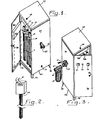
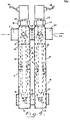
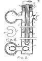
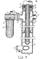
La Fig.1 est une vue en perspective du dispositif montrant la structure en boîtier extérieure et les éléments de sté rilisation qui contiennent les générateurs; la Fig.2 est une vue en perspective du générateur avec tête de protec tion; la Fig.3 est une vue en perspective du dispositif avec filtre des impuretés en suspension auto-nettoyant et soupape de réglage du débit du liquide en entrée avec le vier de commande gradué; la Fig.4 est une vue en élévation des deux éléments, dans lesquels sont insérés les relatifs générateurs, munis de diaphragmes plats et courbés en sens contraire au mouvement du liquide; la Fig.5 est une vue en élévation en coupe d'un élément prévu pour l'accouplement à d'autres en série, montrant le collecteur d'entrée et le collecteur de passage relié à l'élément avec conduit d'u nion muni d'orifice elliptique;la Fig.6 est une vue en plan du diaphragme plat spécial avec portion interrompue pour la descente du liquide dans la profondeur de l'élément; la Fig.? est une vue en élévation en coupe de l'élément prévu pour un dispositif avec élément unique.Fig.1 is a perspective view of the device showing the structure in the outer casing and the sterilization elements which contain the generators; Fig.2 is a perspective view of the generator with protective head; Fig.3 is a perspective view of the device with filter of impurities in self-cleaning suspension and valve for adjusting the flow rate of the input liquid with the graduated control sink; Fig.4 is an elevational view of the two elements, into which are inserted the relative generators, provided with flat diaphragms and curved in opposite directions to the movement of the liquid; Fig.5 is a sectional elevation view of an element intended for coupling to others in series, showing the inlet manifold and the flow manifold connected to the element with a union conduit provided of elliptical opening; Fig. 6 is a plan view of the special flat diaphragm with interrupted portion for the descent of the liquid into the depth of the element; Fig.? is a sectional elevation view of the element provided for a device with a single element.
Les Figures montrent un dispositif de stérilisation, c'est-à-dire les Figures 1, 2, 3, 4 et 5 se réfèrent au type avec plusieurs éléments, la Fig.7 se réfère au type avec un seul élément et les Fig. 6 et 5 sont communes aux deux types de dispositif.The Figures show a sterilization device, i.e. Figures 1, 2, 3, 4 and 5 refer to the type with several elements, Fig. 7 refers to the type with a single element and Figs. 6 and 5 are common to both types of device.
La constitution de base du type de dispositif avec plusieurs éléments comprend un collecteur 1 d'entrée et un collecteur 12 de passage du liquide communiquant avec deux éléments 3 et 14 tubulaires.The basic constitution of the type of device with several elements comprises an
L'élément 3 est relié au collecteur 1 moyennant le con duit 2 d'union, dans lequel l'élément 3 est relié au collecteur 12 au moyen du conduit 11.The
A l'entrée du dispositif est placé le filtre 19 des impuretés en suspension auto-nettoyant, pourvu, vers la descente, d'une soupape 20 de réglage du débit avec un levier 21.At the inlet of the device is placed the
Le deuxième élément 14, joint au 3, est relié à un conduit 15 de passage du liquide. Les éléments 3 et 14 sont constitués par une structure 4 creuse tubulaire avec parois 16 inté rieures lisses dans lesquelles sont logés les générateurs 28, avec réacteurs connectés au réseau électrique, insérés dans les gaines 26 de quartz optique tubulaires, avec diamètre supérieur à celui des générateurs 28, placées au centre 18 de la structure 4 avec fond 17. Les parois 16 possèdent des diaphragmes plats 5 percés 10 et des diaphragmes 6 recourbés avec bague 8 brise-flux placés dans l'élément 3 avec courbu res 5 vers le haut et dans l'élément 14 avec courbures 7 vers le bas, tous les deux étant solidaires et transversaux aux parois 16 et éloignés d'un intervalle 9 des parois 29 exté rieures des gaines 26.The second element 14, joined to 3, is connected to a conduit 15 for passing the liquid. The
L'étranglement de la section des éléments 4 et 14 au moyen des diaphragmes 5, 6 et 7 cause des tourbillons dans la masse li_ quide avec arrêts forcés à proximité des gaines 26 des généra teurs 28 et pour cela un temps majeur d'exposition et pénétra tion des irradiations u.v. dans tout le liquide.The constriction of the section of
L'élément 14 communique avec l'élément 3 et avec le conduit 15 de descente de manière à former un unique système de vases communicants ouvert, en conditions d'équilibre hydrodynamique, avec liquide à pression constante et en mouvement permanent.The element 14 communicates with the
Sur chaque gaine extractible est placé une capsule R4 de blocage avec joint d'étanchéité 25.On each extractable sheath is placed an R4 blocking capsule with
Le dispositif est pourvu d'un robinet 42 de prélèvement du liquide pour l'analyse bactériologique.The device is provided with a
Le générateur 28 est relié au réacteur et au réseau électrique moyennant le fil 30 et est doté d'interrupteur 31.The
Un voyant 27 est placé sur un manchon 46 et un autre voyant 32 lumineux et un minuteur 33 totalisateur des périodes d'utilisation sont positionnés sur un tableau placé sur le volet 35 de la structure 34 extérieure.An
Un couvercle 39 supérieur, qui s'ouvre, permet l'inspection et l'accès aux générateurs 28 et aux gaines extrac tibles. Le couvercle 39 et le volet 35 sont fabriqués de manière hermétique à simple ou double paroi et sont dotés d'une poignée 36 avec serrure.An
La structure 34 présente les parois latérales 47 et 48 et se pose sur le sol avec les pieds 38. Un robinet 37 de vidange du dispositif est placé sur le collecteur 12 et sur la paroi 47. Le filtre 19 est doté d'un robinet 40 de vidange des sédimentations filtrées et d'un robinet 41 pour l'échappement de l'air du filtre 19.The
La constitution de base du type de dispositif avec un seul élément comprend les mêmes principes que celui avec plusieurs éléments, avec les particularités suivantes : l'entrée du liquide qui vient du filtre 19 et de la sou pape 20 arrive directement dans le conduit 2 d'entrée.The basic constitution of the type of device with a single element includes the same principles as that with several elements, with the following peculiarities: the entry of the liquid which comes from the
La sortie du liquide stérilisé arrive dans le conduit 44 de descente pourvu de robinet 43 de prélèvement et vi_ dange du dispositif.The outlet of the sterilized liquid arrives in the
On esplique ci dessous brièvement le fonctionnement du dispositif.The operation of the device is briefly explained below.
L'opérateur doit fermer le circuit électrique à l'aide de l'interrupteur 31 qui allume les générateurs 28.The operator must close the electrical circuit using the
Le liquide arrive au filtre 19 et à travers la soupape 20 arrive au collecteur 1 d'entrée et ensuite au premier élément 3. Puis il descend à travers l'orifice 10 du diaphragme 5 et se met en contact avec les parois 29 de la gaine 26 par l'effet de son rapide mouvement obtenu avec les diaphragmes 5, 6 avec bague 8 et courbures 6 et 7 qui l'obligent à s'écouler dans l'intervalle 9 avec variations en augmentation et diminution de l'énergie cinétique. Puis le liquide arrive au collecteur 12 avec conduit 11 intérieur et orifice 13 elliptique qui mélangent de nouveau toute la masse liquide qui ensuite s'écoule au moyen du conduit 15 d'union dans l'élément 14.The liquid arrives at the
Le liquide passe encore, comme il est montré dans les Fig. 4, 5 et 6, à travers l'intervalle 7 et donc à travers l'orifice 10 du diaphragme 5 au conduit d'écoulement 22 avec passage préalable dans le conduit 15 avec direction de la flèche 23 pour être utilisé ou emmagasiné en récipients stérilisés.The liquid still flows, as shown in Figs. 4, 5 and 6, through the gap 7 and therefore through the
Le dispositif peut s'adapter à plusieurs variations constructives qui ne sortent pas de l'idée de solution de l'invention.The device can adapt to several constructive variations which do not go beyond the idea of a solution of the invention.
On donne ici quelques exemples. Au lieu des diaphragmes 5, 6 et 7 des étranglements et des dilatations peuvent être réalisés, de manière alternée, intérieurement aux éléments 3 et 14 pour obtenir des mouvements turbulents dans le li_ quide. En outre le dispositif peut être fabriqué avec éléments jumélés avec deux ou plusieurs couples d'éléments reliés entre eux par des conduits d'union séparés de parois 49. Dans le premier couple d'éléments le liquide descend et dans le deuxième couple il monte en augmentant, par l'ef fet du double passage, le temps d'exposition du liquide aux rayons u.v.Here are some examples. Instead of the
Les éléments 3 et 14 de stérilisation pourront être placés, par rapport au collecteur 1, sur un côté ou sur les deux côtés ou de manière alternée. Pour des dispositifs avec débit supérieur à 15.000 litres/heure, la structure 34 pourra avoir des formes et des encombrements différents s'adaptant aux nécessités; en outre sont prévues: la fabri cation avec double paroi des côtés extérieurs 47 et 48, du couvercle 39 et du volet 35 de la structure 34, ainsi que le placement du tableau des instruments et de chaque appa reil électrique sur les côtés 47 et 48 avec plusieurs volets pour l'inspection à l'intérieur, non montrés dans les Figures. Il a été prévu une électro-vanne qui pourvoit à fermer la descente du liquide en cas de panne du dispositif.The
Le dispositif relatif à cette invention est en particulier adapté à détruire tous les types de bactéries, même les plus résistantes, comme par exemple, dans le cas de stérilisation de l'eau, le streptocoque fécal, le coliforme, l'escherichia coli, le clostride sultito-réducteur et d'autres encore. Ces bactéries originales ou dérivées sont complètement détruites par les rayons u.v. parce que ceux-ci pénètrent rationnellement en vertu du nouveau procédé de sterilisation avec le maximum d'énergie dans toute la masse du liquide dans le dispositif.The device relating to this invention is in particular suitable for destroying all types of bacteria, even the most resistant, such as, for example, in the case of water sterilization, fecal streptococcus, coliform, escherichia coli, sultito-reducing clostride and others . These original or derived bacteria are completely destroyed by UV rays because these penetrate rationally by virtue of the new sterilization process with the maximum of energy in the whole mass of the liquid in the device.
Naturellement, le principe de l'invention ne variant pas, les formes d'exécution et pratiquement tous les détails de réalisation pourront largement varier, en rapport à ce qui a été expliqué et montré, sans sortir du cadre de la présente invention.Naturally, the principle of the invention does not vary, the embodiments and practically all the details of embodiment may vary widely, in relation to what has been explained and shown, without departing from the scope of the present invention.
Claims (6)
Applications Claiming Priority (2)
| Application Number | Priority Date | Filing Date | Title |
|---|---|---|---|
| IT2477979 | 1979-07-31 | ||
| IT7924779A IT1123509B (en) | 1979-07-31 | 1979-07-31 | PLANT FOR THE STERILIZATION OF LIQUIDS IN GENERAL BY ULTRAVIOLET RADIATION AND RELATED PROCEDURE |
Publications (1)
| Publication Number | Publication Date |
|---|---|
| EP0023892A1 true EP0023892A1 (en) | 1981-02-11 |
Family
ID=11214702
Family Applications (1)
| Application Number | Title | Priority Date | Filing Date |
|---|---|---|---|
| EP80830053A Withdrawn EP0023892A1 (en) | 1979-07-31 | 1980-07-21 | Process and apparatus for sterilizing liquids by ultraviolet radiation |
Country Status (4)
| Country | Link |
|---|---|
| EP (1) | EP0023892A1 (en) |
| ES (1) | ES8105570A1 (en) |
| GR (1) | GR69886B (en) |
| IT (1) | IT1123509B (en) |
Cited By (10)
| Publication number | Priority date | Publication date | Assignee | Title |
|---|---|---|---|---|
| GB2161467A (en) * | 1984-05-14 | 1986-01-15 | Kenneth Greenwood Lickiss | Water/purifier/sterilizer/chiller |
| EP0202820A2 (en) * | 1985-05-24 | 1986-11-26 | W.M. STILL & SONS LIMITED | An ultra violet ray water purifier |
| WO1995015294A1 (en) * | 1993-12-03 | 1995-06-08 | Louis Szabo | Uv water sterilizer with turbulence generator |
| EP0811579A2 (en) * | 1993-03-05 | 1997-12-10 | Trojan Technologies Inc. | UV-fluid treatment system and process |
| ES2112085A1 (en) * | 1992-05-29 | 1998-03-16 | Brasfilter Ind Comercio | Water purifying and sterilizing apparatus |
| DE19653083A1 (en) * | 1996-12-19 | 1998-06-25 | Wedeco Gmbh | Streamlined UV disinfection device |
| DE19708148A1 (en) * | 1997-02-28 | 1998-09-03 | Umex Ges Fuer Umweltberatung U | Electrodeless ultraviolet gas discharge lamp excited by high frequency oscillator |
| US5885449A (en) * | 1996-05-09 | 1999-03-23 | Eisenwerke Fried.Wilh.Duker Gmbh & Co. | Apparatus for removing microbes from flowing media, such as water |
| USRE36896E (en) * | 1993-03-05 | 2000-10-03 | Trojan Technologies Inc. | Fluid treatment system and process |
| US8127667B2 (en) | 2009-03-27 | 2012-03-06 | Gea Farm Technologies, Inc. | Apparatus for pasteurizing milk for feeding to calves |
Families Citing this family (1)
| Publication number | Priority date | Publication date | Assignee | Title |
|---|---|---|---|---|
| IT1408715B1 (en) | 2008-12-17 | 2014-07-03 | Parmegiani | DEVICE AND METHOD FOR STERILIZATION OF LIQUID NITROGEN IN THE LIQUID PHASE USING ULTRAVIOLET RADIATION. |
Citations (12)
| Publication number | Priority date | Publication date | Assignee | Title |
|---|---|---|---|---|
| FR413233A (en) * | 1909-11-05 | 1910-08-03 | Victor Henri | Improvements to sterilization devices |
| DE888446C (en) * | 1942-05-22 | 1953-08-31 | Siemens Ag | Device for irradiating substances, in particular liquids, with ultraviolet rays |
| CH330145A (en) * | 1955-04-23 | 1958-05-31 | Keller Hans | Device for disinfecting water by means of ultraviolet radiation |
| US3061721A (en) * | 1960-01-19 | 1962-10-30 | Brenner Al | Automatic tube cleaning device |
| FR80549E (en) * | 1961-07-21 | 1963-05-10 | Device for sterilizing water by ultraviolet rays with prior sterilization of the pipes | |
| US3182193A (en) * | 1962-01-03 | 1965-05-04 | Ultra Dynamics Corp | Electronically monitored liquid purification or sterilizing system |
| GB1167578A (en) * | 1966-07-29 | 1969-10-15 | Ultra Dynamics Corp | Ultraviolet Liquid Purifier |
| DE1916540A1 (en) * | 1968-04-03 | 1969-11-13 | Erex Hydro Engineering Pty Ltd | Process for the sterilization of liquid and gaseous media by means of ultraviolet radiation and equipment for carrying out this process |
| US3672823A (en) * | 1970-03-25 | 1972-06-27 | Wave Energy Systems | Method of sterilizing liquids |
| US3923663A (en) * | 1974-07-22 | 1975-12-02 | William P Reid | Fluid purification device |
| DE2551622A1 (en) * | 1973-02-17 | 1977-06-02 | Reiner Dipl Ing Wiest | Sterilising liquids by ultraviolet radiation with ozonised air - in two vessel circuit recycling air for intensified action |
| DE2622637A1 (en) * | 1976-05-20 | 1977-11-24 | Franz Boehnensieker | Water sterilised by ultraviolet emitters in pipe - esp. of quartz with external reflective coating esp. of aluminium |
-
1979
- 1979-07-31 IT IT7924779A patent/IT1123509B/en active
-
1980
- 1980-07-21 EP EP80830053A patent/EP0023892A1/en not_active Withdrawn
- 1980-07-31 ES ES493903A patent/ES8105570A1/en not_active Expired
- 1980-07-31 GR GR62579A patent/GR69886B/el unknown
Patent Citations (12)
| Publication number | Priority date | Publication date | Assignee | Title |
|---|---|---|---|---|
| FR413233A (en) * | 1909-11-05 | 1910-08-03 | Victor Henri | Improvements to sterilization devices |
| DE888446C (en) * | 1942-05-22 | 1953-08-31 | Siemens Ag | Device for irradiating substances, in particular liquids, with ultraviolet rays |
| CH330145A (en) * | 1955-04-23 | 1958-05-31 | Keller Hans | Device for disinfecting water by means of ultraviolet radiation |
| US3061721A (en) * | 1960-01-19 | 1962-10-30 | Brenner Al | Automatic tube cleaning device |
| FR80549E (en) * | 1961-07-21 | 1963-05-10 | Device for sterilizing water by ultraviolet rays with prior sterilization of the pipes | |
| US3182193A (en) * | 1962-01-03 | 1965-05-04 | Ultra Dynamics Corp | Electronically monitored liquid purification or sterilizing system |
| GB1167578A (en) * | 1966-07-29 | 1969-10-15 | Ultra Dynamics Corp | Ultraviolet Liquid Purifier |
| DE1916540A1 (en) * | 1968-04-03 | 1969-11-13 | Erex Hydro Engineering Pty Ltd | Process for the sterilization of liquid and gaseous media by means of ultraviolet radiation and equipment for carrying out this process |
| US3672823A (en) * | 1970-03-25 | 1972-06-27 | Wave Energy Systems | Method of sterilizing liquids |
| DE2551622A1 (en) * | 1973-02-17 | 1977-06-02 | Reiner Dipl Ing Wiest | Sterilising liquids by ultraviolet radiation with ozonised air - in two vessel circuit recycling air for intensified action |
| US3923663A (en) * | 1974-07-22 | 1975-12-02 | William P Reid | Fluid purification device |
| DE2622637A1 (en) * | 1976-05-20 | 1977-11-24 | Franz Boehnensieker | Water sterilised by ultraviolet emitters in pipe - esp. of quartz with external reflective coating esp. of aluminium |
Cited By (18)
| Publication number | Priority date | Publication date | Assignee | Title |
|---|---|---|---|---|
| GB2161467A (en) * | 1984-05-14 | 1986-01-15 | Kenneth Greenwood Lickiss | Water/purifier/sterilizer/chiller |
| EP0202820A2 (en) * | 1985-05-24 | 1986-11-26 | W.M. STILL & SONS LIMITED | An ultra violet ray water purifier |
| GB2175779A (en) * | 1985-05-24 | 1986-12-03 | Still & Sons Ltd W M | An ultra violet ray water purifier |
| EP0202820A3 (en) * | 1985-05-24 | 1988-06-15 | W.M. STILL & SONS LIMITED | An ultra violet ray water purifier |
| GB2175779B (en) * | 1985-05-24 | 1989-07-19 | Still & Sons Ltd W M | An ultra violet ray water purifier |
| ES2112085A1 (en) * | 1992-05-29 | 1998-03-16 | Brasfilter Ind Comercio | Water purifying and sterilizing apparatus |
| EP0811579A2 (en) * | 1993-03-05 | 1997-12-10 | Trojan Technologies Inc. | UV-fluid treatment system and process |
| EP0811579A3 (en) * | 1993-03-05 | 1998-01-14 | Trojan Technologies Inc. | UV-fluid treatment system and process |
| USRE36896E (en) * | 1993-03-05 | 2000-10-03 | Trojan Technologies Inc. | Fluid treatment system and process |
| EP1094035A2 (en) * | 1993-03-05 | 2001-04-25 | Trojan Technologies Inc. | Fluid treatment system |
| EP1094035A3 (en) * | 1993-03-05 | 2001-10-31 | Trojan Technologies Inc. | Fluid treatment system |
| WO1995015294A1 (en) * | 1993-12-03 | 1995-06-08 | Louis Szabo | Uv water sterilizer with turbulence generator |
| US5885449A (en) * | 1996-05-09 | 1999-03-23 | Eisenwerke Fried.Wilh.Duker Gmbh & Co. | Apparatus for removing microbes from flowing media, such as water |
| DE19653083A1 (en) * | 1996-12-19 | 1998-06-25 | Wedeco Gmbh | Streamlined UV disinfection device |
| DE19653083B4 (en) * | 1996-12-19 | 2005-09-08 | Wedeco Ag Water Technology | Streamlined UV disinfection device |
| DE19708148A1 (en) * | 1997-02-28 | 1998-09-03 | Umex Ges Fuer Umweltberatung U | Electrodeless ultraviolet gas discharge lamp excited by high frequency oscillator |
| US8127667B2 (en) | 2009-03-27 | 2012-03-06 | Gea Farm Technologies, Inc. | Apparatus for pasteurizing milk for feeding to calves |
| US8448569B2 (en) | 2009-03-27 | 2013-05-28 | Gea Farm Technologies, Inc. | Apparatus for treating milk |
Also Published As
| Publication number | Publication date |
|---|---|
| GR69886B (en) | 1982-07-20 |
| ES493903A0 (en) | 1981-06-16 |
| IT1123509B (en) | 1986-04-30 |
| IT7924779A0 (en) | 1979-07-31 |
| ES8105570A1 (en) | 1981-06-16 |
Similar Documents
| Publication | Publication Date | Title |
|---|---|---|
| EP0023892A1 (en) | Process and apparatus for sterilizing liquids by ultraviolet radiation | |
| RU2204416C2 (en) | Device for disinfecting water by applying ultraviolet radiation | |
| KR880701113A (en) | Fluid Purification Device | |
| WO1993007091A1 (en) | Ultra-violet wastewater disinfection system | |
| GB2175777A (en) | Improvements in and relating to water purifiers | |
| FR2714594A3 (en) | Medicinal hub infusion dispenser | |
| US4482431A (en) | Distillation apparatus with a liquid-vapor separating device having three chambers | |
| JPH04227097A (en) | Pasteurizing and disinfecting device | |
| WO2000068152A1 (en) | Method and apparatus for fluid treatment by uv-radiation | |
| EP0106847A1 (en) | Water purifying apparatus | |
| DK0762821T3 (en) | Device for filtering an electrically insulating and heat-conducting liquid environment and power electronics unit comprising a seed | |
| FR2461254A1 (en) | Water quality measuring device - with pump and sensors in immersed box joined by umbilical cord to land station | |
| CN217498746U (en) | Ultraviolet ray drinking water degassing unit | |
| JP4172048B2 (en) | UV irradiation disinfection device for treated water | |
| FR2515655A1 (en) | Ultraviolet steriliser for inlet of domestic water tank - has bottom outlet which fits several different diameters of tank inlet | |
| WO2002074350A1 (en) | Device for decontaminating endocardial medical catheters and probes | |
| RU13211U1 (en) | DEVICE FOR WATER TREATMENT BY UV RADIATION | |
| CN212451016U (en) | Ultraviolet sterilization water purifier | |
| CN214829166U (en) | Ultraviolet sterilization purifies play water installation | |
| JPS5581784A (en) | Sterilizer for polluted water | |
| SU767527A2 (en) | Liquid batcher | |
| SU741906A1 (en) | Laboratory extractor | |
| RU2039336C1 (en) | Condensation heating apparatus | |
| FR2498237A1 (en) | Automatic dosing mechanism for swimming pool - uses piston controlled tap to add sterilising fluid in proportion to increased level following rainfall | |
| SU1569371A1 (en) | Water outlet |
Legal Events
| Date | Code | Title | Description |
|---|---|---|---|
| PUAI | Public reference made under article 153(3) epc to a published international application that has entered the european phase |
Free format text: ORIGINAL CODE: 0009012 |
|
| AK | Designated contracting states |
Designated state(s): AT BE CH DE FR GB LU NL SE |
|
| DET | De: translation of patent claims | ||
| DET | De: translation of patent claims | ||
| 17P | Request for examination filed |
Effective date: 19810817 |
|
| STAA | Information on the status of an ep patent application or granted ep patent |
Free format text: STATUS: THE APPLICATION IS DEEMED TO BE WITHDRAWN |
|
| 18D | Application deemed to be withdrawn |
Effective date: 19831104 |