EP0019428A1 - Projectile locating apparatus - Google Patents
Projectile locating apparatus Download PDFInfo
- Publication number
- EP0019428A1 EP0019428A1 EP80301517A EP80301517A EP0019428A1 EP 0019428 A1 EP0019428 A1 EP 0019428A1 EP 80301517 A EP80301517 A EP 80301517A EP 80301517 A EP80301517 A EP 80301517A EP 0019428 A1 EP0019428 A1 EP 0019428A1
- Authority
- EP
- European Patent Office
- Prior art keywords
- projectile
- signal
- plane
- signal producing
- time difference
- Prior art date
- Legal status (The legal status is an assumption and is not a legal conclusion. Google has not performed a legal analysis and makes no representation as to the accuracy of the status listed.)
- Granted
Links
Images


Classifications
-
- F—MECHANICAL ENGINEERING; LIGHTING; HEATING; WEAPONS; BLASTING
- F41—WEAPONS
- F41J—TARGETS; TARGET RANGES; BULLET CATCHERS
- F41J5/00—Target indicating systems; Target-hit or score detecting systems
- F41J5/06—Acoustic hit-indicating systems, i.e. detecting of shock waves
-
- G—PHYSICS
- G01—MEASURING; TESTING
- G01S—RADIO DIRECTION-FINDING; RADIO NAVIGATION; DETERMINING DISTANCE OR VELOCITY BY USE OF RADIO WAVES; LOCATING OR PRESENCE-DETECTING BY USE OF THE REFLECTION OR RERADIATION OF RADIO WAVES; ANALOGOUS ARRANGEMENTS USING OTHER WAVES
- G01S3/00—Direction-finders for determining the direction from which infrasonic, sonic, ultrasonic, or electromagnetic waves, or particle emission, not having a directional significance, are being received
- G01S3/80—Direction-finders for determining the direction from which infrasonic, sonic, ultrasonic, or electromagnetic waves, or particle emission, not having a directional significance, are being received using ultrasonic, sonic or infrasonic waves
- G01S3/802—Systems for determining direction or deviation from predetermined direction
- G01S3/808—Systems for determining direction or deviation from predetermined direction using transducers spaced apart and measuring phase or time difference between signals therefrom, i.e. path-difference systems
- G01S3/8083—Systems for determining direction or deviation from predetermined direction using transducers spaced apart and measuring phase or time difference between signals therefrom, i.e. path-difference systems determining direction of source
-
- G—PHYSICS
- G01—MEASURING; TESTING
- G01S—RADIO DIRECTION-FINDING; RADIO NAVIGATION; DETERMINING DISTANCE OR VELOCITY BY USE OF RADIO WAVES; LOCATING OR PRESENCE-DETECTING BY USE OF THE REFLECTION OR RERADIATION OF RADIO WAVES; ANALOGOUS ARRANGEMENTS USING OTHER WAVES
- G01S5/00—Position-fixing by co-ordinating two or more direction or position line determinations; Position-fixing by co-ordinating two or more distance determinations
- G01S5/18—Position-fixing by co-ordinating two or more direction or position line determinations; Position-fixing by co-ordinating two or more distance determinations using ultrasonic, sonic, or infrasonic waves
- G01S5/20—Position of source determined by a plurality of spaced direction-finders
-
- Y—GENERAL TAGGING OF NEW TECHNOLOGICAL DEVELOPMENTS; GENERAL TAGGING OF CROSS-SECTIONAL TECHNOLOGIES SPANNING OVER SEVERAL SECTIONS OF THE IPC; TECHNICAL SUBJECTS COVERED BY FORMER USPC CROSS-REFERENCE ART COLLECTIONS [XRACs] AND DIGESTS
- Y10—TECHNICAL SUBJECTS COVERED BY FORMER USPC
- Y10S—TECHNICAL SUBJECTS COVERED BY FORMER USPC CROSS-REFERENCE ART COLLECTIONS [XRACs] AND DIGESTS
- Y10S367/00—Communications, electrical: acoustic wave systems and devices
- Y10S367/906—Airborne shock-wave detection
Definitions
- THE INVENTION relates to apparatus for determining the location of a point on a reference plane through which the trajectory of a projectile passes, from the shock or pressure waves produced by the projectile. More particularly the invention relates to an apparatus for determining the inclination angle of the trajectory of a projectile through a predetermined plane relative to a predetermined point on a first reference line in the plane, and to an apparatus for additionally determining the inclination angle of the trajectory relative to a second predetermined point and thus for determining the location of the point on said plane through which said trajectory passes.
- a number of systems are known for determining the location at which a projectile passes through or strikes a predetermined plane.
- U.S.A. Patent No.3,022,076 to ZITO teaches a system in which a projectile strikes the rigid surface of a target to generate shock waves which emanate from the point of impact on the target.
- Detectors are mounted near the edge of two or more sides of .the target surface, and produce output signals in response to shock waves. By meansuring the time differentials of the detector outputs, the exact location of the point of impact may be determined by converting the time relationships into distance measurements.
- U.S.A. Patent No.3,678,495 to GILBERT similarly discloses a target system in which transducers are spaced evenly around a rigid metal target. Acoustic waves developed in the target upon impact of a projectile are detected by transducers. The output of the transducers enables computation of the location of the point of impact.
- Airbourne shockwaves are detected by other types of systems.
- U.S.A. Patent No.2,535,255 to BARNES et al teaches a system for locating the source of sound waves, in which two microphones are spaced apart along a base line. The time interval between arrival of sound at the microphones is detected and, from that, partial information about the origin of the sound source may be derived.
- U.S.A. Patent No.3,489,413 to GRODER et al teaches a system in which a plurality of bi-drectional transducers is arranged to monitor target zones and to indicate through which zone a projectile has passed.
- U.S.A. Patent No.2,925,582 to MATTEI et al teaches a target system in which microphones are placed on a circular crown around the target.
- the transducer output signals are employed to deflect the beam of a cathode ray tube to indicate the location at which the projectile passes through the target plane.
- U.S.A. Patent No.3,985,024 to HORAK discloses a further transducer array for determining the location of an acoustic source.
- U.S.A. Patent No.3,778,059 to ROHRBAUGH et al discloses further an automatic target system responsive to the airborne acoustic shock wave produced by a projectile.
- Mutually perpendicular elongated acoustic energy conductors are located adjacent the perimeter of the target and have one or more acoustic transducers attached to an end or ends thereof. Electrical signals are produced by the acoustic transducers in response to detected shock waves, and appropriate circuitry determines the location of each "hit" on the target in rectangular coordinates.
- the systems detecting airborne shock waves also generally require transducers to be spaced apart in an array which is not easily protectable in a target range. It would be preferable to have a system in which the transducers, or detecotrs, are located only along the bottom edge of the target, where they may be easily protected by means of an earth embankment or the like. Transducers, or detectors, positioned along the side or top edges of the target plane are not desirable due to the liklihood of damage being caused by badly aimed rounds.
- an apparatus for determining the inclination angle of the trajectory of a projectile through a predetermined plane relative to a predetermined point on a first reference line in the plane said apparatus comprises first vibration transmitting means having a surface defining an arc in the plane and having two ends, for transmitting vibrations caused by an airborne shock or pressure wave generated by the supersonic projectile; first and second means, operatively coupled to the respective ends of the first vibration transmitting means, for producing respective output signals in response to the transmitted vibrations; timing circuit meanscperatively coupled for producing a first signal representing a time difference between the output signals of said first and second signal producing means; and computing means operative to calculate from the time difference signal the inclination angle of the supersonic projectile trajectory relative to the first reference line.
- the projectile is supersonic.
- an apparatus for additionally determining the inclination angle of the trajectory relative to a second predetermined point and thus for determining the location of the point on said plane through which said trajectory passes, said apparatus further comprises second vibration transmitting means spaced from the first said means and having a surface defining an arc in the plane and having tw ends, for transmitting vibrations caused by the airborne shock or pressure wave generated by the supersonic projectile to the two ends thereof; and third and fourth means operatively coupled to the respective ends of said second vibration transmitting means, for producing respective output signals in response to vibration transmitting means, said timing circuit means being further operatively coupled for producing a second signal representing a time difference between the output signals of the third and fourth signal producing means, and said computing means being further operative to calculate from the second time difference signal the inclination of the supersonic projectile trajectory relative to said second predetermined point' and thus the location of said point.
- an apparatus for determining the location of a point on a reference plane through which the trajectory of a projectile passes comprising: a framework at least one sheet of material capable of being penetrated by a projectile, covering said framework to form a chamber and forming a target surface generally parallel to the reference plane; first and second vibration transmitting means located at respective spaced locations within said chamber, each said vibration transmitting means having a surface defining an arc in the plane and having two ends, and each said vibration transmitting means transmitting to the two ends thereof vibrations caused by an airborne pressure wave of the supersonic projectile within said chamber; first and second signal producing means operatively coupled to the respective ends of said first vibration transmitting means and third and fourth signal producing means operatively coupled to the respective ends of said second,vibration transmitting means, said first, second, third, and fourth signal producing means generating respective output signals in response to the transmitted vibrations; timing circuit means operatively coupled for producing first signal representing a time difference between the output signals of the first and second
- An apparatus of the present invention can be employed in a firing range for tracing marksman, the apparatus indicating the position at which a bullet passes through a predetermined target plane but the invention has the advantage that since the invention transmitting means and associated devices need be positioned only along a single edge of the target plane, they may therefore easily shield from damage by stray bullets. Thus the only item exposed to fire is the target member at which the projectiles are aimed. Thus the apparatus should not be damaged.
- the vibration transmitting member is preferably a rod or elongate member bent or formed in an arc, the arc being of constant radius and extending over a quarter or semi-circle.
- the transducers preferably comprise piezoelectric elements suitably connected to provide respective output signals.
- each piezoelectric element is secured to an interior end wall surface of a metal housing.
- the exterior end wall surface of the housing is secured to the vibration transmitting member end, so that the shock waves are transmitted to the piezoelectric element.
- the vibration transmitting member is a curved, elongate member of piezoelectric material having a pair of conductive pickup electrodes at each end, each pair of electrodes providing a transducer output signal.
- the transducer output signals are provided .to respective amplifiers, and then to threshold detectors.
- the threshold detector outputs are connected to a timing circuit which measures the time difference between the instants of arrival of vibrations at the ends of the vibration transmitting member.
- the timing circuit has two counters, one associated with each transducer or electrode pair.
- the counter associated with the transducer or electrode pair which first receives a vibration begins counting when the first transducer or electrode pair receives the vibration and stops counting when the second transducer or electrode pair receives the vibration.
- the counter counts output pulses from a clock signal generator.
- a calculating circuit or programmed computer determines from the resultant clock count the angle of inclination of the origin of the vibration detected relative to a predetermined point on a reference line in the target plane.
- Two detectors each having a vibration transmitting member and associated transducers or pickup electrodes for providing output signals, may be provided at spaced-apart locations in a common plane, the calculating circuit or programmed computer being operative to determine the location in the reference plane of the source of the projectile generated shock or pressure wave which causes the vibration.
- shock wave as used herein is intended to mean a pressure or shock wave of this type.
- Deceleration of the projectile as it passes along its trajectory, acceleration of the projectile downwardly as a result of the effect of gravity, and the movement of the air through which the projectile is passing (i.e. wind) may affect the propagation of the shock wave somewhat.
- the present invention relates to apparatus for locating a point on the trajectory of projectile, for example, in target shooting. While it is preferred that projectiles attaining supersonic velocity be used with the apparatus, at least one form of the invention operates effectively with subsonic projectiles by detecting a pressure wave within a chamber caused by penetration of the projectile through a wall of the chamber, as will be explained in greater detail below.
- FIG. 1 shows generally a shock or pressure wave detector 10 in accordance with the present invention.
- Detector 10 preferably comprises a curved bar 12 of uniform circular cross section 16, the cross section being preferably about 0.6 cms (1/4 inch).
- the bar 12 is curved with a regular radius of curvature 14, the radius of curvature being about 7.6 cms (3 inches) in a preferred form of the invention.
- Bar 12 is constructed of a material which readily transmits vibrations along its length at a velocity greater than the propagation velocity of a shock wave in air.
- the bar is especially transmissive of mechanical pressure pulses having a short rise time, such as those induced in the bar by the shock or pressure wave from a passing projectile.
- the curved bar 12 is made of cured epoxy resin such as MY 750 resin mixed with MY 753 hardener, available from CIBA (ARL) Ltd. of Duxford, Cambridge, England. This material has been found to have good mechanical vibration transmission properties and provides relatively higher output signals than other materials when used in conjunction with the preferred transducer assembly.
- a transducer assembly 18 is mechanically coupled to each end of curved bar 12 for converting mechanical pressure pulses within the bar into corresponding electrical signals.
- Each transducer assembly 18 comprises a disc-shaped ceramic piezoelectric element 24, such as type MB 1043, available from Mullard Company Ltd. of Mullard House, Torrington Place, London, England.
- Each piezoelectric element 24 is secured to the centre of a circular end wall 22 of a machined aluminium housing 20 with a thin coating of electrically conductive epoxy resin 32, such as "E-Solder" E-3021, z available from CIBA GIEGY (PTY) Ltd. of Orion Road, Lane Cove, Sydney, Australia.
- housing end wall 22 is bonded to one end of curved bar 12 with a thin layer 36 of the same epoxy resin of which curved bar 12 is made. Vibrations induced in curved bar 12 by the shock or pressure wave from a passing projectile are transmitted through end wall 22 and resin layer 32 to the piezoelectric element 24.
- the structure of the transducer assembly is shown in enlarged, partially cut-away view in Figure 2.
- Bonded or otherwise secured to the rear face of disc-shaped piezoelectric element 24 is a section of a rod of ceramic material 26, having the same diameter as the disc-shaped piezodectric element 24.
- Rod 26 preferably has the same chemical and physical composition as the piezoelectric element, but is preferably manufactured by a modified process so as to have no significant piezoelectric properties itself.
- rod 26 can be replaced by a number of piezoelectric elements, of the same type as element 24, bonded together with thin layers of epoxy resin to form a stack of appropriate length.
- Rod 26 whether a ceramic member or a stack of piezoelectric elements, has a length which is more than twice the thickness of the piezoelectric element 24.
- rod 26 acts as a stub waveguide so that vibrations passing through piezoelectric element 24 and reflected from the free end of rod 26 back to piezoelectric element 24 do not arrive until well after piezoelectric element 24 has completed its initial response to the first part of a short rise time pulse in order to provide an output signal of considerable magnitude.
- Rod 26 is preferably bonded to element 24 with an electrically conductive epoxy resin, such as "E-Sdder” type E-3021, and portions of this conductive adhesive material protrude slightly around the sides of the interface between the mating surfaces of element 24 and rod 26, as shown at 38 in Figure 2, A small-diameter conductive wire 28 is embedded in this protruding portion of the conductive adhesive material 38, and wire 28 is further connected to the centre lead of a coaxial cable 30.
- the shield portion 40 of the coaxial cable is mechanically and electrically bonded to aluminum housing 20 by suitable means.
- each element 24 is bonded by a conductive adhesive layer 32 to aluminium housing end wall 22, which in turn is bonded by a layer 34 of such conductive adhesive to the main portion of the aluminum housing 20. Housing 20 is, in turn, electrically connected to the shield 40 of coaxial cable 30. The other face of element 24 is bonded by a conductive resin 38 to wire 28 which is connected to the centre lead of the coaxial cable 30.
- vibra- . tions in the bar will result in generation of signals from transducer assemblies 18 which appear on the res p ec- tive coaxial cables 30.
- Coaxial cables 30 lead from respective transducers 18 to wide-band high-gain amplifiers 42, as shown in Figure 3. It will be understood that any suitable amplifier of this type may be used, but the circuit of Figure 3 represents a preferred embodiment.
- the integrated circuit amplifier is of type TI EF 152, available from Texas Instruments Inc., P. O. Box 5012, Dallas, Texas, U.S.A. It is well known that the output voltage of the type of amplifier illustrated in Figure 3 at any particular instant in time is directly related to the input current at that time.
- the input/output relationship of the amplifier can be approximated by the mathematical expression Where V out is the output voltage at any instant of time, T in is the input current at any instant of time, and RF is a constant of proportionality.
- the response of a piezoelectric element can be approximately defined as Where Q o is the instantaneous charge imbalance within the element as a function of time, K 1 is a constant or proportionality, S 1 is the mechanical strain applied to the piezoelectric element, varying with time and integrated over the volume of the element, and t is the independent variable of time.
- K 2 is a new constant of proportionality equal to RFK 1 .
- the output voltage is proportional to the instantaneous rate of change of net strain in piezoelectric element 24.
- a piezoelectric device If a piezoelectric device is subjected to a relatively low-frequency vibration, the rate of change in applied strain at any particular instant of time is relatively low and, thus, the output voltage of the transducer will be low. However, if the transducer is subjected to a high-frequency vibration, the output voltage is relatively high because the instantaneous rate of change in applied strain is high.
- a high- amplitude signal is generated by each piezoelectric element 24 in response to a high-frequency strain applied to the transducer as a result of vibrations in curved bar 12 induced by the shock or pressure wave from a passing projectile.
- the detector arrangement described with reference to Figures 1 and 2 therefore facilitates dection of the shock or pressure wave generated by a passing projectile and inherently discriminates against low-frequency vibrations which may be induced in curved bar 12 as a result of wind or other factors.
- Figure 4 illustrates a preferred threshold detector circuit for providing logic output signals in response to amplified output signals of the transducers associated with the shock or pressure wave detector arrangement shown in Figure 1.
- the threshold detector circuit has two inputs 42 each coupled to the output 43 in an amplifier 4 2 as in Figure 3) which in turn is coupled at its input to a respective transducer.
- the threshold detector circuit 44 preferably-comprises an integrated circuit type LM 1514, available from National Semiconductor Limited, Bedford, United Kingdom.
- the integrated circuit has two differential input comparators "A" and "B".
- the amplified output signal of a first transducer is supplied through an appropriate coupling capacitor to input terminal 6 of comparator"A", and a reference voltage is provided to a second input terminal 5,
- This reference voltage is appropriately set by adjustment of the associated 100 ohm potentiometer,
- the reference voltage is preferably controlled by means of a Zener diode, as shown.
- the amplified output signal of the second transducer associated with curved bar 12 is provided through an apropriate coupling capacitor to input terminal 13 of comparator "B".
- a reference voltage determined by adjustment of the associated 100 ohm potentiometer is supplied to input terminal 12 of comparator "B”.
- the output 46 of comparator “A” is at a logic “high” level in the quiescent state, but quickly changes to a "low” logic level when an output signal above a predetermined threshold level is received from the associated transducer.
- the output 47 of comparator “B” is at a logic “high” level in the quiescent state, and quickly changes to a logic "low” level in response to a signal above the preset threshold from the associated transducer.
- threshold detector circuit 44 two logic output signals are provided by the threshold detector circuit 44, each signal representing the time at which a shock or pressure wave is detected by the corresponding transducer.
- One threshold detector circuit 44 as shown in Figure 4 is required for each shock wave detector arrangement of Figure 1.
- Timing logic circuit 50 is coupled to a clock pulse generator circuit 52 which supplies clock pulses at a constant, known frequency and which has a 1 MH 2 crystal.
- clock pulse generator circuit 52 which supplies clock pulses at a constant, known frequency and which has a 1 MH 2 crystal.
- counters CTR 1A and CTR 1B are activated to begin counting fixed-interval pulses from clock pulse generator 52. The counting proceeds until the output of threshold detector comparator "B” changes state, and then the counting is stopped.
- the number of clock pulse intervals counted by counters CTR lA and CTR 1B represents the time difference between the instants of detection of a given shock or pressure wave by the two transducers associated with curved bar 12.
- counters CTR 2A and CTR 2B begin to count clock pulses and continue counting until the output of threshold detector comparator "A" changes state.
- the number of clock pulse intervals counted by counters CTR 2A and CTR 2B represent the time difference between instants of detection of a shock wave by the two transducers associated with curved bar 12.
- Counters CTR lA, CTR 1B, CTR 2A, and CTR 2B preferably each comprise an integrated circuit of type SN74LS90M, available from Texas Instruments, Inc.
- Timing logic circuit 46 includes a pair of bistable multi. vibratozs 53, 54 which ensure that, after the first time each threshold detector comparator changes state, the timing logic circuit will respond correctly during counting, despite subsequent changing of the threshold detector output states.
- the bistable multivibrators are reset by depressing manual reset switch 55. Thus, only the leading edge of a shock or pressure wave is detected, and output signals generated by the transducers in response to successive wave fronts of the shock or pressure wave are ignored by the timing logic circuit.
- the bistable multivibrators preferably comprise an integrated circuit of type SX74LS74N, available from Texas Instruments, Inc.
- a "readtv” lamp circuit 56 is also coupled to the timing logic circuit 5Q which illuminates to indicate when the bistable multivibrators have been reset, that is, when the timing logic circuit is ready to determine a new time difference between the instants of shock or pressure wave detection by the transducers, and which extinguishes when a projectile is detected to indicate that data is' pressure wave detection by the transducers, and which extinguishes when a projectile is detected to indicate that data is ready for processing.
- Ready lamp circuit 48 is coupled to the bistable multivibrators through a gate, comprising one fourth of an integrated circuit of type SN74LSOON.
- the output of this gate changes from a logic "high” state to a logic “low” state when counters CTR 1A and CTR 1B or counters CTR 2A and CTR 2B contain a count representing, in binary form, the number of clock pulse intervals which elapse between triggering of threshold detector comparator "A" and triggering of threshold detector "B".
- the ready lamp circuit 56 is also connected by lead 58 to a corresponding point on the logic circuitry associated with a second sensor, if such a second sensor is provided.
- Line 59 is a reset line.
- timing logic circuit 50 is suitable for use with a single shock or pressure wave detector as shown in Figure 1. If additional such shock or pressure.wave detectors 10 are to be simultaneously employed, a respective timing logic circuit 46 must be supplied for each detector 18. However, oulv one each of the ready lampcircuit 58, manual reset switch 55, and clock pulse generator 52 need be employed and the connection of these components to additional timing logic circuits 50 will be apparent to those skilled in the art.
- FIG. 6 shows diagrammatdcallv the warmer in which the apparatus of the present invcntion may be used on the firing range.
- the firing range includes a target o2 which may be, for example, a planar sheet of plywood or cardboard erected in a vertical position and, optionally, having a target outline (not shown) marked thereon.
- a marksman (not shown) positions himself squarely in front of and at a distance from the target, preferably at a predetermined firing point.
- An earth embankment or other protective arrangement (not shown) is preferably provided in front of and beneath the target to prevent damage to the shock wave detectors from stray bullets. Behind the earth embankment, and lying in a plane parallel to the plane of the target, are two detectors 18 of the type shown in Figure 1.
- FIG. 6 shows schematically at 64 the point at which the trajectory of a supersonic bullet passes through the plane of the shock or pressure wave detectors.
- the shock wave generated by the bullet expands radially outwardly as indicated at 66.
- the expanding shock wave contacts a first one of the detectors at point 68, the shock wave initially reaching the vibration transmitting bar of the detector at a tangent point which lies on a straight line joining point 64 and the centre of the radius of curvature of the detector bar.
- the shock wave consequently generates vibrations within the bar which are propagated at a velocity greater than the velocity of sound wave propagation in air. Vibrations generated in the bar are transmitted therethrough to the transducers located at the respective ends of the bar.
- Transducer B will receive the vibrations before they are received by transducer A, and this time difference can be expressed mathematically.
- The-time difference between the instants of initiation of electrical output signals from transducers B and A is given by
- T diff the difference between instants of initiation of signals from the transducers
- D l the path length traversed by the pressure pulse travelling counterclockwise through the bar to transducer A
- D 2 the path length traversed by the pressure pulse travelling clockwise through the bar to transducer B
- v p the effective velocity of propagation of pressure pulses through the curved bar
- transducers A and B are coupled through respective amplifiers to respective inputs of a threshold detector circuit 44 as shown in Figure 4,
- the expanding shock wave strikes the curved vibration transmitting member of the right-hand shcck wave detector shown in Figure 6 at a tangential point 67.
- Vibrations in the curved bar are transmitted to transducer C over a path length D 3 and to transducer D over a path length D 4 .
- the outputs of transducers C and D are provided to respective amplifiers as shown in Figure 3 and then to respective inputs of a threshold detector circuit 44 as shown in Figure 4,
- the outputs of the corresponding threshold detector circuit 44 are provided to a second timing logic circuit 5 0 of the type shown in Figure 5.
- the counters associated with transducer C may be labelled CTR 3A and CTR 3B, respectively (corresponding to counters CTR lA and CTR 1B in Figure 5).
- counters associated with transducer D may be labelled CTR 4A and CTR 4B, respectively (corresponding to counters CTR 2A and.CTR 2B in Figure 5).
- the point 64 through which the bullet passes may be determined by simple trigonometric calculation
- Figure 7 shows a block diagram of the overall system. for determining angles ⁇ 1 and ⁇ 2 of Figure 6, as well as the location of paint 64 in the plane of the detectors through which the bullet trajectory passes. Shown in Figure 7 are two of the shock or pressure wave detectors 10, which may be positioned relative to a target as shown in Figure 6. The outputs of transducers A, B, C, and D are supplied through respective amplifiers 42 to threshold detector circuits 44, as indicated.
- Timing logic circuit 50 associated with transducers A and B has counters CTR 1A, CTR 1B, CTR 2A, and CTR 2B, which provide in binary signal form on res p ec- tive groups of four lines, B, C, D, E, the number of clock generator pulse intervals registered thereon, Similarly, timing logic circuit 50 associated with transducers C and D has counters CTR 3A, CTR 3B, CTR 4A and CTR 4B, which provide im binary signal form on respective groups of four lines F, G, H, I, the numbers of clock generator pulses registered thereon.
- the groups of output lines B, C, D, E, F, G, H, and I are connected to pins of an interface card 74, preferably of type 98133A, available from Hewlett Packard.
- the connection of counter ouiput pins to interface card pins is provided in the table of Appendix A.
- the interface card is plug-compatible with the Hewlett-Packard desk-top calculator 76 type 9815A/S, which is programmed to calculate angles 6 1 and ⁇ 2 as well as the X, Y coordinates of point 54 in the detector plane through which the bullet trajectory passes.
- the desk-top calculator is programmed by depression of keys on the calculator in the sequence given in Appendix A, which follows.
- the preferred desk-top calculator type 9815A/S is manufactured by the Hewlett Packard Co. Inc.,5301 Stevens Creek Boulevard, Santa Clara, California, U.S.A.
- This device is programmed by manual operation of its keyboard while in the "program” mode, and serves to automatically execute the sequence of operations defined by the key depressions when returned to the "run” mode.
- any other suitable calculating device having appropriate input/output interface devices and peripheral devices, such as graphic displays, may be used and appropriately programmed.
- Figure 8 of the accompanying drawings showsdiagram- matically a marksman 78 firing a bullet along a trajectory 80 at a target (not shown) lying behind an imaginary vertical measurement plane 82.
- Detectors 84 are arranged along the bottom edge of the target area, lying substantially in the measurement plane.
- the marksman is located at a firing point predetermined such that the trajectory 80 of a bullet fired by the marksman is substantially normal to the measurement plane.
- a visible target (not shown) is preferably arranged in or lying somewhat behind the measurement plane and substantially parallel thereto.
- the expanding shock or pressure wave generated by the bullet induces vibrations in the curved bars of detectors 84, these vibrations being transmitted to the transducers and operated upon as described above to determine the angle of inclination of the bullet trajectory through measurement plane 82 relative to each shock wave detector 84, as well as the point on measurement plane 82 through which the bullet trajectory passes.
- an earth embankment 86 may be provided in front of detectors 84 to prevent damage from badly aimed bullets.
- the coordinates of the point on measurement plane 82 through which the bullet trajectory 80 passes can be simply printed out, as in the program of Appendix A, or can be further used to determine whether.the bullet "hit” or"missed” a particular zone in target plane 82 and/or to allocate a "score" to the particular round fired.
- Such information may be displayed at a point near the trainee marksman or at any other suitable point, on appropriate apparatus such as a cathode-ray tube display.
- the accuracy of the device can be increased by using three or more of detectors 84 to provide redundancy of measurement, and the program for the calculator can be modified accordingly.
- shock wave detectors are preferably arranged along a common reference line in the measurement plane, as shown in Figure 6 (for simplicity of calculation), but may be positioned on co-parallel or intersecting lines lying within the plane or may even be canted slightly out of the plane without substantial reduction in accuracy or increase in calculating effort.
- FIG. 9 shows a target apparatus assembly in accordance with the invention, in front elevational view.
- the assembly includes a rigid rectangular frame 122 constructed preferably of hardwood, having an external width of, for example, about 2 metres.
- a flexible membrane 124 covers the front of target frame 122 down to line A-A, and a similar membrane (not show) covers the rear of target frame 122, defining a hollow chamber.
- a suitable material for the front and rear membranes is 3 mm thick "Linatex" available from Linatex Australia Ltd., Sinclair Road, D andong, Victoria, Australia. It will be understood, however, that other suitable materials may be used for the front and rear membranes, such as neoprene foam material, Plastazote, or other materials having suitable properties.
- Hardwood trapping strips 123 serve to retain the front and rear flexible membranes on the target frame.
- the lower section of frame 122 includes a cross-member 126 of hardwood.
- the lower interior portion of target frame 122 between cross-member 126 and line A-A is covered with 8 mm thick hardwood plywood, both front and rear, thereby defining a cavity for receiving the shock or pressure wave detectors 10 and other components,.
- a detector support beam 128 extends across the lower portion of the target chamber, and is mounted to the side members and cross-member 126 of target frame 122 by means of anti-vibration mountings 134-144.
- Suitable anti-vibration mountings 134-144 are, for example, Type No. E220240, manufactured by Barry Controls Inc., 700 Pleasant Street, Watertown, Massachusetts, U.S.A.
- the target arrangement of Figure 9 may be constructed in any suitable dimension, it is contemplated that the outermost ring of the concentric rings forming a bull's-eye on the front membrane 124 of the target be nearly 2m in diameter. A target of this size is suitable for target practice over a distance of approximately 500m.
- the target frame 121 is mounted, for example, behind a mantlet which shields the lower portion of the target assembly lying below line A-A in Figure 9.
- Such mantlet may comprise an earthen embankment and/or concrete shield for preventing the detector support beam 128 and components mounted thereon from being damaged by bullets or other projectiles fired at the target.
- acoustic pulse source 145 Shown mounted on support beam 128 in Figure 9, are an acoustic pulse source 145 and acoustic pulse sensors 146, 147, which may be employed for measuring the propagation velocity of sound in air within the target chamber, as will be explained in greater detail below.
- shock or pressure wave transducers 10 of the target arrangement in Figure 9 may be connected, as shown in Figure 7, to suitable apparatus for transducer output signal processing and calculation of X, Y coordinates of the point at which the bullet trajectory passes through the target apparatus.
- X, Y coordinates will, of course, be calculated in the plane of the detectors 10; if the detector planes is closely adjacent the front membrane 124 of the target assembly and if the bullet is fired along a trajectory which is substantially normal to the detector plane and front membrane 124 of the target assembly, the calculated X, Y coordinates will accurately indicate the location at which the bullet penetrated the front membrane 124.
- the box-like target apparatus is also not sensitive to variations in the speed of sound propagation in air, as are some prior art target systems (for example, as disclosed in German Utility Model Application DE-GM 77 26 275, published March 16, 1978).
- the target apparatus of Figure 9, with detectors 10 connected as shown in Figure 7, is capable of accurate position fixing without any speed of sound-in-air measurement, it is possible that the calculated "X" value (horizontal position) will show in- creasingl y large errors in the lower region of the target, This is because the X, Y position coordinates are essentially derived from calculation of the intersection point of two lines which extend respectively from the detectors.
- This error can be largely compensated by measuring the difference in time of arrival of the shock- or pressure- wave-induced vibrations detected at the inner transducers "B" and “C” of the detectors 10, 10 and calculating from this time difference the "X" value of the shot position. This calculation does require at least an estimated value for the velocity of sound propagation in air, however. Assuming the "Y" value has already been calculated, the "X" value is given by
- Equation 11 is solved for X, e.g., by iteration. Alternatively if Ywhere "d" is the spacing between detectors, then
- V S is the velocity of sound in air within the target chamber
- ⁇ t is the difference in time of arrival of a detected vibration at transducers "B" and "C” in Figure 10. While this method of calculating the "X" value for small values of "Y” would also have some errors, such as timing errors, velocity of sound value errors and errors due to the assumption of Y d/2, it is useful if employed only in calculation of X,Y position coordinates for projectiles in the zone where these errors are less significant than those from the intersecting line calculation.
- Figure 11 shows schematically a modified circuit arrangement for use with the target assembly of Figure 9.
- the output signals from transducers "A”, “B”, “C”, and “D” are provided through respective amplifiers 42 to threshold detector circuits 44.
- threshold detector outputs "A” and “B” are provided to one timing logic circuit 50 I and threshold detector outputs "C” and “D” are provided to another timing logic circuit 50 III, as in Figure 7.
- threshold detector outputs "B” and “C” are provided to a further timing logic circuit 50 II, which can be connected to provide to interface 1 64 a binary signal indicating a number of clock pulses representing the time difference between threshold detector output signals "B” and “C”, which may be employed in calculator 166 for solving Equation 11 or Equation 13 for example when the "Y" shot position coordinate from the intersecting lines calculation is below a predetermined value.
- Calculator 166 can be provided with an estimated or assumed value for the speed of sound propagation in air, or may be provided with information from which this value is calculated.
- a value for the temperature of air in the target chamber may be automatically or manually fed to the calculator, as disclosed in Co-pending European Patent Application No.79 30 2820.0 filed 7th December 1979.
- an acoustic pulse source such as a spark gap device 145 connected to a high voltage pulse generator 148 is provided in the lower portion of the target chamber.
- the high voltage pulse generator is suitably triggered manually or automatically to produce a spark across the device 145 which results in an acoustic pulse detectable by additional transducers 146, 147.
- pulse generator 148 is triggered by a delayed pulse generator circuit 149.
- a delayed pulse generator circuit 149 may comprise two mono stable multivibrators in tandem, which are triggered by a pulse at the output of the amplifier 42 associated with the transducer D. After a predetermined time delay, defined by the time constants of the multivibrators, a delayed pulse from the circuit 149 triggers the high voltage pulse generator 148, and thus the acoustic pulse is generated when any reverberations generated by the passage of the bullet have died down.
- Transducers 146, 147 are coupled through respective amplifiers 42 and a further threshold detector circuit 44 to a further timing logic circuit 50 IV. It will be appreciated that the actual speed of sound in air can thus readily be calculated from the time difference between signals E and F and the known distance between transducers 146, 147.
- the timing logic circuits 50 are connected to the interface 164 by an 8 pole gaged two way switch 150.
- the arrangement is such that either circuits 50 I and 50 III are connected to interface 164, or circuits 50 III and 50 IV are connected to the interface 164.
- the switch 150 With the switch in the position illustrated the data on circuits 50 I and 50 III will be loaded and the program will act on the data. Subsequently the switch 150 will be operated and the program will then act on the data of circuits 50 II and 50 IV.
- The-switch 150 may, of course, be controlled by appropriate logic.
- Figure 12 shows an alternate construction of s shock or pressure wave detector assembly 210.
- the assembly 210 of Figure 12 comprises a curved bar 212 formed as a single piece of piezoelectric material, such as a ceramic material having piezoelectric properties.
- Curved bar 212 preferably has a uniform circular cross-section and a uniform radius of curvature 214 over its length. At each end of the bar is affixed a pair of conductive pickup electrodes 216, 218 at appropriate points for picking up potential differences across the bar end.
- the electrodes 216 and 218 of Figure 12 may be formed in a variety of ways such as vacuum deposition of a metallic layer or coating with electrically conducting compounds such as"E-Solder" E-3021.
- assembly 21C of Figure 12 has a number of advantages, including the hardness and robustness of the single piece of ceramic material and the fact that the output signals would not be limited by acoustic mismatch between a vibration transmitting bar and associated transducer elements. Further, it is expected that assembly 210 can be accurately and yet inexpensively produced in quantity. It is recognized, however, that detecting the time difference between output signals of assembly 210 may be more critical because of much faster propagation velocity of the vibrations in a ceramic bar than in an epoxy resin bar.
- the curved bar 12 or 212 of Figures 1 and 12, respectively, are shown having a constant radius of curvature enclosing an angle of about 1 80 0 .
- the enclosed angle may be reduced to nearer 90 0 if the curved bars are rotated about their centre of curvature by 45 0 , with the "apex" of curvature pointing toward the "bull" 312 of the target, as shown in Figure 13.
- Corresponding modification to the computer program sequence of Appendix "A" is needed to compensate for the slightly differing geometry of this configuration, which can be readily implemented by the skilled artisan.
Abstract
Description
- THE INVENTION relates to apparatus for determining the location of a point on a reference plane through which the trajectory of a projectile passes, from the shock or pressure waves produced by the projectile. More particularly the invention relates to an apparatus for determining the inclination angle of the trajectory of a projectile through a predetermined plane relative to a predetermined point on a first reference line in the plane, and to an apparatus for additionally determining the inclination angle of the trajectory relative to a second predetermined point and thus for determining the location of the point on said plane through which said trajectory passes.
- A number of systems are known for determining the location at which a projectile passes through or strikes a predetermined plane.
- For example U.S.A. Patent No.3,022,076 to ZITO, teaches a system in which a projectile strikes the rigid surface of a target to generate shock waves which emanate from the point of impact on the target. Detectors are mounted near the edge of two or more sides of .the target surface, and produce output signals in response to shock waves. By meansuring the time differentials of the detector outputs, the exact location of the point of impact may be determined by converting the time relationships into distance measurements.
- U.S.A. Patent No.3,678,495 to GILBERT similarly discloses a target system in which transducers are spaced evenly around a rigid metal target. Acoustic waves developed in the target upon impact of a projectile are detected by transducers. The output of the transducers enables computation of the location of the point of impact.
- Systems of the type described above have a number of disadvantages for use in marksmanship training. All detect shock waves transmitted through a rigid target member and, when such a member is used in marksmanship training with live ammunition, the target member must be frequently replaced or repaired. Those systems which do not require transducers along more than one edge of the target area, such as in U.K. Patent No.969,929, are not particularly accurate, since they can only indicate that a projectile has struck a given target area and cannot indicate the precise location of the point of impact. Those systems which can determine the point of impact require transducers to be positioned along at least two edges of the target area. This presents a problem when using live ammunition on a firing range because transducers positioned along the side or top edges of the target surface may be struck by theammunition, causing damage to the target system.
- Airbourne shockwaves are detected by other types of systems. For example, U.S.A. Patent No.2,535,255 to BARNES et al, teaches a system for locating the source of sound waves, in which two microphones are spaced apart along a base line. The time interval between arrival of sound at the microphones is detected and, from that, partial information about the origin of the sound source may be derived.
- U.S.A. Patent No.3,489,413 to GRODER et al, teaches a system in which a plurality of bi-drectional transducers is arranged to monitor target zones and to indicate through which zone a projectile has passed.
- U.S.A. Patent No.2,925,582 to MATTEI et al, teaches a target system in which microphones are placed on a circular crown around the target. The transducer output signals are employed to deflect the beam of a cathode ray tube to indicate the location at which the projectile passes through the target plane.
- U.S.A. Patent No.3,985,024 to HORAK, discloses a further transducer array for determining the location of an acoustic source.
- U.S.A. Patent No.3,778,059 to ROHRBAUGH et al, discloses further an automatic target system responsive to the airborne acoustic shock wave produced by a projectile. Mutually perpendicular elongated acoustic energy conductors are located adjacent the perimeter of the target and have one or more acoustic transducers attached to an end or ends thereof. Electrical signals are produced by the acoustic transducers in response to detected shock waves, and appropriate circuitry determines the location of each "hit" on the target in rectangular coordinates.
- As with the target systems which detect target transmitted shock waves, the systems detecting airborne shock waves also generally require transducers to be spaced apart in an array which is not easily protectable in a target range. It would be preferable to have a system in which the transducers, or detecotrs, are located only along the bottom edge of the target, where they may be easily protected by means of an earth embankment or the like. Transducers, or detectors, positioned along the side or top edges of the target plane are not desirable due to the liklihood of damage being caused by badly aimed rounds.
- According to one aspect of this invention there is provided an apparatus for determining the inclination angle of the trajectory of a projectile through a predetermined plane relative to a predetermined point on a first reference line in the plane, said apparatus comprises first vibration transmitting means having a surface defining an arc in the plane and having two ends, for transmitting vibrations caused by an airborne shock or pressure wave generated by the supersonic projectile; first and second means, operatively coupled to the respective ends of the first vibration transmitting means, for producing respective output signals in response to the transmitted vibrations; timing circuit meanscperatively coupled for producing a first signal representing a time difference between the output signals of said first and second signal producing means; and computing means operative to calculate from the time difference signal the inclination angle of the supersonic projectile trajectory relative to the first reference line.
- Preferably the projectile is supersonic.
- According to another aspect of the invention there is provided an apparatus for additionally determining the inclination angle of the trajectory relative to a second predetermined point and thus for determining the location of the point on said plane through which said trajectory passes, said apparatus further comprises second vibration transmitting means spaced from the first said means and having a surface defining an arc in the plane and having tw ends, for transmitting vibrations caused by the airborne shock or pressure wave generated by the supersonic projectile to the two ends thereof; and third and fourth means operatively coupled to the respective ends of said second vibration transmitting means, for producing respective output signals in response to vibration transmitting means, said timing circuit means being further operatively coupled for producing a second signal representing a time difference between the output signals of the third and fourth signal producing means, and said computing means being further operative to calculate from the second time difference signal the inclination of the supersonic projectile trajectory relative to said second predetermined point' and thus the location of said point.
- According to a further aspect of the invention there is provided an apparatus for determining the location of a point on a reference plane through which the trajectory of a projectile passes, comprising: a framework at least one sheet of material capable of being penetrated by a projectile, covering said framework to form a chamber and forming a target surface generally parallel to the reference plane; first and second vibration transmitting means located at respective spaced locations within said chamber, each said vibration transmitting means having a surface defining an arc in the plane and having two ends, and each said vibration transmitting means transmitting to the two ends thereof vibrations caused by an airborne pressure wave of the supersonic projectile within said chamber; first and second signal producing means operatively coupled to the respective ends of said first vibration transmitting means and third and fourth signal producing means operatively coupled to the respective ends of said second,vibration transmitting means, said first, second, third, and fourth signal producing means generating respective output signals in response to the transmitted vibrations; timing circuit means operatively coupled for producing first signal representing a time difference between the output signals of the first and second signal producing means and a second signal representing a time difference between the output signals of the third and fourth signal producing means; and computing means operative to calculate the location of said point on the reference plane through which the trajectory of the projectile passes, from the first and second time difference signals and from the locations of said first and second transmitting means.
- An apparatus of the present invention can be employed in a firing range for tracing marksman, the apparatus indicating the position at which a bullet passes through a predetermined target plane but the invention has the advantage that since the invention transmitting means and associated devices need be positioned only along a single edge of the target plane, they may therefore easily shield from damage by stray bullets. Thus the only item exposed to fire is the target member at which the projectiles are aimed. Thus the apparatus should not be damaged.
- The vibration transmitting member is preferably a rod or elongate member bent or formed in an arc, the arc being of constant radius and extending over a quarter or semi-circle. The transducers preferably comprise piezoelectric elements suitably connected to provide respective output signals. In one preferred embidiment, each piezoelectric element is secured to an interior end wall surface of a metal housing. The exterior end wall surface of the housing is secured to the vibration transmitting member end, so that the shock waves are transmitted to the piezoelectric element. In another form, the vibration transmitting member is a curved, elongate member of piezoelectric material having a pair of conductive pickup electrodes at each end, each pair of electrodes providing a transducer output signal.
- The transducer output signals are provided .to respective amplifiers, and then to threshold detectors. The threshold detector outputs are connected to a timing circuit which measures the time difference between the instants of arrival of vibrations at the ends of the vibration transmitting member. In a preferred form, the timing circuit has two counters, one associated with each transducer or electrode pair. The counter associated with the transducer or electrode pair which first receives a vibration begins counting when the first transducer or electrode pair receives the vibration and stops counting when the second transducer or electrode pair receives the vibration. The counter counts output pulses from a clock signal generator.
- A calculating circuit or programmed computer determines from the resultant clock count the angle of inclination of the origin of the vibration detected relative to a predetermined point on a reference line in the target plane. Two detectors, each having a vibration transmitting member and associated transducers or pickup electrodes for providing output signals, may be provided at spaced-apart locations in a common plane, the calculating circuit or programmed computer being operative to determine the location in the reference plane of the source of the projectile generated shock or pressure wave which causes the vibration.
- In the embodiment in which two detectors, each with a vibration transmitting member and associated transducers or pickup electrodes, are located in respective lower corners of a chamber defined by a framework covered with a sheet of material penetrable by the projectile, it is not necessary for the projectile to be travelling at supersonic velocity; the projectile generates a pressure wave within the chamber which expands radially outwardly from the projectile trajectory and which is detectable by the detectors.
- In order that the invention may be more readily understood and so that further features thereof may be appreciated the invention will now be described by way of example with reference to the accompanying drawings in which:
- FIGURE 1 is a partial elevational view of a single shock or pressure wave detector in accordance with the present invention;
- FIGURE 2 is an enlarged cut-away view of a part of the shock or pressure wave detector of Figure 1;
- FIGURE 3 is a circuit diagram for an amplifier suitable for use with the detector of Figures 1 and 2;
- FIGURE 4 shows a circuit diagram of a threshold detector circuit suitable for use with the shock or pressure wave detector of Figures 1 and 2;
- FIGURE 5 is a timing logic circuit diagram for determining the time difference between output signals of the shock or pressure wave detector transducers of Figure 1 and 2;
- FIGURE 6 shows an arrangement for determining the point at which a projectile passes through a target plane, employing two of the detectors according to Figure 1;
- FIGURE 7 is a block diagram of a complete apparatus in accordance with one form of the invention for determining the location of passage of a projectile through a predetermined plane;
- FIGURE 8 shows a target range equipped with two of the detectors shown in Figure 1;
- FIGURE 9 shows a target framework covered with sheets of material to form a chamber, with pressure wave detectors in a lower region of the chamber,
- FIGURE 10 is a diagrammatic representation oi' an apparatus in accordance with the invention showing the effect which errors in determining inclination angle of a point on the projectile trajectory relative to a reference line in a plane have on the calculated position of a point at which the trajectory intersects the plane;
- FIGURE 11 is a block diagram of a circuit for the target apparatus of Figure 9;
- FIGURE 12 is a diagrammatic representation of a shock or pressure wave detector which is formed of piezoelectric ceramic material and which is provided with a pair of pickup electrodes at each end; and
- FIGURE 13 shows an arrangement of shortened shock or pressure wave detectors.
- A supersonic projectile, such as a bullet, propagates a conical or substantially conical shock or pressure wave as it passes Through the atmosphere, the apex of the shock wave being adjacent the front of the supersonic projectile and the axis of symmetry of the conical pressure or shock wave closely corresponding to the trajectory of the supersonic projectile. The term "shock wave" as used herein is intended to mean a pressure or shock wave of this type.
- Deceleration of the projectile as it passes along its trajectory, acceleration of the projectile downwardly as a result of the effect of gravity, and the movement of the air through which the projectile is passing (i.e. wind) may affect the propagation of the shock wave somewhat. However, with regard to the degree of accuracy attained by the present invention, it is not necessary to consider the effects of deceleration, wind, or gravity.
- The present invention relates to apparatus for locating a point on the trajectory of projectile, for example, in target shooting. While it is preferred that projectiles attaining supersonic velocity be used with the apparatus, at least one form of the invention operates effectively with subsonic projectiles by detecting a pressure wave within a chamber caused by penetration of the projectile through a wall of the chamber, as will be explained in greater detail below.
- Figure 1 shows generally a shock or
pressure wave detector 10 in accordance with the present invention.Detector 10 preferably comprises acurved bar 12 of uniformcircular cross section 16, the cross section being preferably about 0.6 cms (1/4 inch). Thebar 12 is curved with a regular radius ofcurvature 14, the radius of curvature being about 7.6 cms (3 inches) in a preferred form of the invention.Bar 12 is constructed of a material which readily transmits vibrations along its length at a velocity greater than the propagation velocity of a shock wave in air. The bar is especially transmissive of mechanical pressure pulses having a short rise time, such as those induced in the bar by the shock or pressure wave from a passing projectile. In a preferred embodiment of the invention, thecurved bar 12 is made of cured epoxy resin such as MY 750 resin mixed with MY 753 hardener, available from CIBA (ARL) Ltd. of Duxford, Cambridge, England. This material has been found to have good mechanical vibration transmission properties and provides relatively higher output signals than other materials when used in conjunction with the preferred transducer assembly. - As shown in Figure 1, a
transducer assembly 18 is mechanically coupled to each end ofcurved bar 12 for converting mechanical pressure pulses within the bar into corresponding electrical signals. Eachtransducer assembly 18 comprises a disc-shaped ceramicpiezoelectric element 24, such as type MB 1043, available from Mullard Company Ltd. of Mullard House, Torrington Place, London, England. Eachpiezoelectric element 24 is secured to the centre of acircular end wall 22 of a machinedaluminium housing 20 with a thin coating of electrically conductiveepoxy resin 32, such as "E-Solder" E-3021, z available from CIBA GIEGY (PTY) Ltd. of Orion Road, Lane Cove, Sydney, Australia. The corresponding outer face ofhousing end wall 22 is bonded to one end ofcurved bar 12 with athin layer 36 of the same epoxy resin of which curvedbar 12 is made. Vibrations induced incurved bar 12 by the shock or pressure wave from a passing projectile are transmitted throughend wall 22 andresin layer 32 to thepiezoelectric element 24. - The structure of the transducer assembly is shown in enlarged, partially cut-away view in Figure 2. Bonded or otherwise secured to the rear face of disc-shaped
piezoelectric element 24 is a section of a rod ofceramic material 26, having the same diameter as the disc-shapedpiezodectric element 24.Rod 26 preferably has the same chemical and physical composition as the piezoelectric element, but is preferably manufactured by a modified process so as to have no significant piezoelectric properties itself. Alternatively,rod 26 can be replaced by a number of piezoelectric elements, of the same type aselement 24, bonded together with thin layers of epoxy resin to form a stack of appropriate length.Rod 26, whether a ceramic member or a stack of piezoelectric elements, has a length which is more than twice the thickness of thepiezoelectric element 24. Thus,rod 26 acts as a stub waveguide so that vibrations passing throughpiezoelectric element 24 and reflected from the free end ofrod 26 back topiezoelectric element 24 do not arrive until well afterpiezoelectric element 24 has completed its initial response to the first part of a short rise time pulse in order to provide an output signal of considerable magnitude.Rod 26 is preferably bonded toelement 24 with an electrically conductive epoxy resin, such as "E-Sdder" type E-3021, and portions of this conductive adhesive material protrude slightly around the sides of the interface between the mating surfaces ofelement 24 androd 26, as shown at 38 in Figure 2, A small-diameterconductive wire 28 is embedded in this protruding portion of the conductiveadhesive material 38, andwire 28 is further connected to the centre lead of acoaxial cable 30. Theshield portion 40 of the coaxial cable is mechanically and electrically bonded toaluminum housing 20 by suitable means. - It will be appreciated that when a projectile-generated shock or pressure wave impinges on
curved bar 12, vibrations generated in the bar will be transmitted totransducers 18, causing a potential difference between the opposing faces of eachpiezoelectric element 24. One face of eachelement 24 is bonded by a conductiveadhesive layer 32 to aluminiumhousing end wall 22, which in turn is bonded by alayer 34 of such conductive adhesive to the main portion of thealuminum housing 20.Housing 20 is, in turn, electrically connected to theshield 40 ofcoaxial cable 30. The other face ofelement 24 is bonded by aconductive resin 38 to wire 28 which is connected to the centre lead of thecoaxial cable 30. Thus, vibra- . tions in the bar will result in generation of signals fromtransducer assemblies 18 which appear on the respec- tivecoaxial cables 30. -
Coaxial cables 30 lead fromrespective transducers 18 to wide-band high-gain amplifiers 42, as shown in Figure 3. It will be understood that any suitable amplifier of this type may be used, but the circuit of Figure 3 represents a preferred embodiment. The integrated circuit amplifier is oftype TI EF 152, available from Texas Instruments Inc., P. O. Box 5012, Dallas, Texas, U.S.A. It is well known that the output voltage of the type of amplifier illustrated in Figure 3 at any particular instant in time is directly related to the input current at that time. The input/output relationship of the amplifier can be approximated by the mathematical expression
- The response of a piezoelectric element can be approximately defined as

- When the piezoelectric element is coupled to an amplifier of the preferred type shown in Figure 3, it is known that the current flow into the amplifier will be given by the expression


- Combining
equations 

piezoelectric element 24. - If a piezoelectric device is subjected to a relatively low-frequency vibration, the rate of change in applied strain at any particular instant of time is relatively low and, thus, the output voltage of the transducer will be low. However, if the transducer is subjected to a high-frequency vibration, the output voltage is relatively high because the instantaneous rate of change in applied strain is high. In the detector arrangement of Figure 1, a high- amplitude signal is generated by each
piezoelectric element 24 in response to a high-frequency strain applied to the transducer as a result of vibrations incurved bar 12 induced by the shock or pressure wave from a passing projectile. The detector arrangement described with reference to Figures 1 and 2 therefore facilitates dection of the shock or pressure wave generated by a passing projectile and inherently discriminates against low-frequency vibrations which may be induced incurved bar 12 as a result of wind or other factors. - Figure 4 illustrates a preferred threshold detector circuit for providing logic output signals in response to amplified output signals of the transducers associated with the shock or pressure wave detector arrangement shown in Figure 1. The threshold detector circuit has two
inputs 42 each coupled to theoutput 43 in anamplifier 42 as in Figure 3) which in turn is coupled at its input to a respective transducer. Thethreshold detector circuit 44 preferably-comprises an integratedcircuit type LM 1514, available from National Semiconductor Limited, Bedford, United Kingdom. The integrated circuit has two differential input comparators "A" and "B". The amplified output signal of a first transducer is supplied through an appropriate coupling capacitor to inputterminal 6 of comparator"A", and a reference voltage is provided to asecond input terminal 5, This reference voltage is appropriately set by adjustment of the associated 100 ohm potentiometer, The reference voltage is preferably controlled by means of a Zener diode, as shown. - The amplified output signal of the second transducer associated with
curved bar 12 is provided through an apropriate coupling capacitor to inputterminal 13 of comparator "B". A reference voltage determined by adjustment of the associated 100 ohm potentiometer is supplied to inputterminal 12 of comparator "B". Theoutput 46 of comparator "A" is at a logic "high" level in the quiescent state, but quickly changes to a "low" logic level when an output signal above a predetermined threshold level is received from the associated transducer. Theoutput 47 of comparator "B" is at a logic "high" level in the quiescent state, and quickly changes to a logic "low" level in response to a signal above the preset threshold from the associated transducer. - Thus, two logic output signals are provided by the
threshold detector circuit 44, each signal representing the time at which a shock or pressure wave is detected by the corresponding transducer. Onethreshold detector circuit 44 as shown in Figure 4 is required for each shock wave detector arrangement of Figure 1. - The logic output signals of comparators "A" and "B" of
threshold detector circuit 44 are provided torespective inputs timing logic circuit 50 as shown in Figure 5. Timinglogic circuit 50 is coupled to a clockpulse generator circuit 52 which supplies clock pulses at a constant, known frequency and which has a 1 MH2 crystal. When, for example, the output of threshold detector comparator "A" changes state to indicate that the associated transducer has detected a shock or pressure wave, counters CTR 1A and CTR 1B are activated to begin counting fixed-interval pulses fromclock pulse generator 52. The counting proceeds until the output of threshold detector comparator "B" changes state, and then the counting is stopped. The number of clock pulse intervals counted by counters CTR lA and CTR 1B represents the time difference between the instants of detection of a given shock or pressure wave by the two transducers associated withcurved bar 12. - Similarly, if the output of threshold detector comparator "B" is first to change state, counters
CTR 2A andCTR 2B begin to count clock pulses and continue counting until the output of threshold detector comparator "A" changes state. The number of clock pulse intervals counted bycounters CTR 2A andCTR 2B represent the time difference between instants of detection of a shock wave by the two transducers associated withcurved bar 12. Counters CTR lA, CTR 1B,CTR 2A, andCTR 2B preferably each comprise an integrated circuit of type SN74LS90M, available from Texas Instruments, Inc. - Timing
logic circuit 46 includes a pair of bistable multi.vibratozs reset switch 55. Thus, only the leading edge of a shock or pressure wave is detected, and output signals generated by the transducers in response to successive wave fronts of the shock or pressure wave are ignored by the timing logic circuit. The bistable multivibrators preferably comprise an integrated circuit of type SX74LS74N, available from Texas Instruments, Inc. Preferably, a "readtv"lamp circuit 56 is also coupled to the timing logic circuit 5Q which illuminates to indicate when the bistable multivibrators have been reset, that is, when the timing logic circuit is ready to determine a new time difference between the instants of shock or pressure wave detection by the transducers, and which extinguishes when a projectile is detected to indicate that data is' pressure wave detection by the transducers, and which extinguishes when a projectile is detected to indicate that data is ready for processing. -
Ready lamp circuit 48 is coupled to the bistable multivibrators through a gate, comprising one fourth of an integrated circuit of type SN74LSOON. The output of this gate, atpoint 57, changes from a logic "high" state to a logic "low" state when counters CTR 1A and CTR 1B or countersCTR 2A andCTR 2B contain a count representing, in binary form, the number of clock pulse intervals which elapse between triggering of threshold detector comparator "A" and triggering of threshold detector "B". Theready lamp circuit 56 is also connected bylead 58 to a corresponding point on the logic circuitry associated with a second sensor, if such a second sensor is provided. -
Line 59 is a reset line. - The remaining integrated circuit components in Figure 5 are indicated by type number, and are available from Texas Instruments, Inc. It will be understood that, although a
manual reset switch 55 is shown in Figure 5, suitable automatic reset may be provided in a manner which will be apparent to those skilled in the art. It will also be understood that timinglogic circuit 50 is suitable for use with a single shock or pressure wave detector as shown in Figure 1. If additional such shock orpressure.wave detectors 10 are to be simultaneously employed, a respectivetiming logic circuit 46 must be supplied for eachdetector 18. However, oulv one each of theready lampcircuit 58,manual reset switch 55, andclock pulse generator 52 need be employed and the connection of these components to additionaltiming logic circuits 50 will be apparent to those skilled in the art. - Figure 6 shows diagrammatdcallv the wanner in which the apparatus of the present invcntion may be used on the firing range. The firing range includes a target o2 which may be, for example, a planar sheet of plywood or cardboard erected in a vertical position and, optionally, having a target outline (not shown) marked thereon. A marksman (not shown) positions himself squarely in front of and at a distance from the target, preferably at a predetermined firing point. An earth embankment or other protective arrangement (not shown) is preferably provided in front of and beneath the target to prevent damage to the shock wave detectors from stray bullets. Behind the earth embankment, and lying in a plane parallel to the plane of the target, are two
detectors 18 of the type shown in Figure 1. - Figure 6 shows schematically at 64 the point at which the trajectory of a supersonic bullet passes through the plane of the shock or pressure wave detectors. The shock wave generated by the bullet expands radially outwardly as indicated at 66. At a first point in time, the expanding shock wave contacts a first one of the detectors at
point 68, the shock wave initially reaching the vibration transmitting bar of the detector at a tangent point which lies on a straightline joining point 64 and the centre of the radius of curvature of the detector bar. The shock wave consequently generates vibrations within the bar which are propagated at a velocity greater than the velocity of sound wave propagation in air. Vibrations generated in the bar are transmitted therethrough to the transducers located at the respective ends of the bar. Transducer B will receive the vibrations before they are received by transducer A, and this time difference can be expressed mathematically. The-time difference between the instants of initiation of electrical output signals from transducers B and A is given by
- The outputs of transducers A and B are coupled through respective amplifiers to respective inputs of a
threshold detector circuit 44 as shown in Figure 4, The time difference between output signals fromthreshold detector 44 is detected by timinglogic circuit 50, by counting clock generator pulses incounters CTR 2A andCTR 2B. Then
counters CTR 2A andCTR 2B, Tdiff = the difference already defined, and Tclock = period of cycle ofclock pulse generator 52. - Preferably, the curved bar of the shock wave detector is of constant radius, conforming to the arc of a circle. Accordingly, the following relationship can be established:

- π = fixed constant, approximately 3.1416
Combining equations 
- Similarly, the expanding shock wave strikes the curved vibration transmitting member of the right-hand shcck wave detector shown in Figure 6 at a
tangential point 67. Vibrations in the curved bar are transmitted to transducer C over a path length D3 and to transducer D over a path length D4. The outputs of transducers C and D are provided to respective amplifiers as shown in Figure 3 and then to respective inputs of athreshold detector circuit 44 as shown in Figure 4, The outputs of the correspondingthreshold detector circuit 44 are provided to a secondtiming logic circuit 50 of the type shown in Figure 5. The counters associated with transducer C may be labelled CTR 3A and CTR 3B, respectively (corresponding to counters CTR lA and CTR 1B in Figure 5). Similarly, counters associated with transducer D may be labelled CTR 4A and CTR 4B, respectively (corresponding tocounters CTR 2A and.CTR 2B in Figure 5). - It will be understood that since the detectors shown in Figure 6 are positioned at predetermined locations along a common reference line in the reference, or target, plane, the
point 64 through which the bullet passes may be determined by simple trigonometric calculation, - Figure 7 shows a block diagram of the overall system. for determining angles θ1 and θ2 of Figure 6, as well as the location of
paint 64 in the plane of the detectors through which the bullet trajectory passes. Shown in Figure 7 are two of the shock orpressure wave detectors 10, which may be positioned relative to a target as shown in Figure 6. The outputs of transducers A, B, C, and D are supplied throughrespective amplifiers 42 tothreshold detector circuits 44, as indicated. The threshold detector circuits provide logic signals upon receipt of pulses from the transducers, as described above, to timinglogic circuits 50Timing logic circuit 50 associated with transducers A and B has counters CTR 1A, CTR 1B,CTR 2A, andCTR 2B, which provide in binary signal form on respec- tive groups of four lines, B, C, D, E, the number of clock generator pulse intervals registered thereon, Similarly, timinglogic circuit 50 associated with transducers C and D has counters CTR 3A, CTR 3B, CTR 4A and CTR 4B, which provide im binary signal form on respective groups of four lines F, G, H, I, the numbers of clock generator pulses registered thereon. The groups of output lines B, C, D, E, F, G, H, and I are connected to pins of aninterface card 74, preferably oftype 98133A, available from Hewlett Packard. The connection of counter ouiput pins to interface card pins is provided in the table of Appendix A. The interface card is plug-compatible with the Hewlett-Packard desk-top calculator 76type 9815A/S, which is programmed to calculateangles 61 and θ2 as well as the X, Y coordinates ofpoint 54 in the detector plane through which the bullet trajectory passes. The desk-top calculator is programmed by depression of keys on the calculator in the sequence given in Appendix A, which follows. - The preferred desk-top calculator,
type 9815A/S is manufactured by the Hewlett Packard Co. Inc.,5301 Stevens Creek Blvd, Santa Clara, California, U.S.A. This device is programmed by manual operation of its keyboard while in the "program" mode, and serves to automatically execute the sequence of operations defined by the key depressions when returned to the "run" mode. However, any other suitable calculating device having appropriate input/output interface devices and peripheral devices, such as graphic displays, may be used and appropriately programmed. - Figure 8 of the accompanying drawings showsdiagram- matically a marksman 78 firing a bullet along a
trajectory 80 at a target (not shown) lying behind an imaginaryvertical measurement plane 82.Detectors 84 are arranged along the bottom edge of the target area, lying substantially in the measurement plane. The marksman is located at a firing point predetermined such that thetrajectory 80 of a bullet fired by the marksman is substantially normal to the measurement plane. A visible target (not shown) is preferably arranged in or lying somewhat behind the measurement plane and substantially parallel thereto. - When a bullet is fired at the target by the marksman, the expanding shock or pressure wave generated by the bullet induces vibrations in the curved bars of
detectors 84, these vibrations being transmitted to the transducers and operated upon as described above to determine the angle of inclination of the bullet trajectory throughmeasurement plane 82 relative to eachshock wave detector 84, as well as the point onmeasurement plane 82 through which the bullet trajectory passes. - In practice, a number of modifications can be made to the system as described above. For example, an
earth embankment 86 may be provided in front ofdetectors 84 to prevent damage from badly aimed bullets. Further, the coordinates of the point onmeasurement plane 82 through which thebullet trajectory 80 passes can be simply printed out, as in the program of Appendix A, or can be further used to determine whether.the bullet "hit" or"missed" a particular zone intarget plane 82 and/or to allocate a "score" to the particular round fired. Such information may be displayed at a point near the trainee marksman or at any other suitable point, on appropriate apparatus such as a cathode-ray tube display. Further, the accuracy of the device can be increased by using three or more ofdetectors 84 to provide redundancy of measurement, and the program for the calculator can be modified accordingly. - It is to be understood that the shock wave detectors are preferably arranged along a common reference line in the measurement plane, as shown in Figure 6 (for simplicity of calculation), but may be positioned on co-parallel or intersecting lines lying within the plane or may even be canted slightly out of the plane without substantial reduction in accuracy or increase in calculating effort.
- Figure 9 shows a target apparatus assembly in accordance with the invention, in front elevational view. The assembly includes a rigid
rectangular frame 122 constructed preferably of hardwood, having an external width of, for example, about 2 metres. Aflexible membrane 124 covers the front oftarget frame 122 down to line A-A, and a similar membrane (not show) covers the rear oftarget frame 122, defining a hollow chamber. A suitable material for the front and rear membranes is 3 mm thick "Linatex" available from Linatex Australia Ltd., Sinclair Road, Dandong, Victoria, Australia. It will be understood, however, that other suitable materials may be used for the front and rear membranes, such as neoprene foam material, Plastazote, or other materials having suitable properties. Hardwood trapping strips 123 serve to retain the front and rear flexible membranes on the target frame. The lower section offrame 122 includes across-member 126 of hardwood. The lower interior portion oftarget frame 122 betweencross-member 126 and line A-A is covered with 8 mm thick hardwood plywood, both front and rear, thereby defining a cavity for receiving the shock orpressure wave detectors 10 and other components,. - A
detector support beam 128 extends across the lower portion of the target chamber, and is mounted to the side members and cross-member 126 oftarget frame 122 by means of anti-vibration mountings 134-144. Suitable anti-vibration mountings 134-144 are, for example, Type No. E220240, manufactured by Barry Controls Inc., 700 Pleasant Street, Watertown, Massachusetts, U.S.A. - Although the target arrangement of Figure 9 may be constructed in any suitable dimension, it is contemplated that the outermost ring of the concentric rings forming a bull's-eye on the
front membrane 124 of the target be nearly 2m in diameter. A target of this size is suitable for target practice over a distance of approximately 500m. In use, thetarget frame 121 is mounted, for example, behind a mantlet which shields the lower portion of the target assembly lying below line A-A in Figure 9. Such mantlet may comprise an earthen embankment and/or concrete shield for preventing thedetector support beam 128 and components mounted thereon from being damaged by bullets or other projectiles fired at the target. - Shown mounted on
support beam 128 in Figure 9, are anacoustic pulse source 145 andacoustic pulse sensors - Those skilled in the art will recognize that shock or
pressure wave transducers 10 of the target arrangement in Figure 9 may be connected, as shown in Figure 7, to suitable apparatus for transducer output signal processing and calculation of X, Y coordinates of the point at which the bullet trajectory passes through the target apparatus. These X, Y coordinates will, of course, be calculated in the plane of thedetectors 10; if the detector planes is closely adjacent thefront membrane 124 of the target assembly and if the bullet is fired along a trajectory which is substantially normal to the detector plane andfront membrane 124 of the target assembly, the calculated X, Y coordinates will accurately indicate the location at which the bullet penetrated thefront membrane 124. - It has been found in practice that, with ` the target assembly of Figure 9, the bullet need not be travelling at supersonic velocity to obtain detector output signals from which X, Y coordinates can be calculated. The box-like target assembly of Figure 9 will operate effectively with subsonic rounds as well, albeit with somewhat reduced," but still acceptable, accuracy. Subsonic projectiles passing through the target assembly generate a radially- expanding pressure wave within the target chamber which is not, strictly speaking, a "shock wave" as generated by a supersonic projectile, but which is nonetheless detectable by the
detectors 10. It will thus be recognized that the box-like target apparatus permits calculation of the X, Y coordinates without sensitivity to bullet velocity, - The box-like target apparatus is also not sensitive to variations in the speed of sound propagation in air, as are some prior art target systems (for example, as disclosed in German Utility
Model Application DE-GM 77 26 275, published March 16, 1978). Although the target apparatus of Figure 9, withdetectors 10 connected as shown in Figure 7, is capable of accurate position fixing without any speed of sound-in-air measurement, it is possible that the calculated "X" value (horizontal position) will show in- creasingly large errors in the lower region of the target, This is because the X, Y position coordinates are essentially derived from calculation of the intersection point of two lines which extend respectively from the detectors. - For low shots, larger "X" value errors are to be expected than for higher shot positions, as will be explained with reference to Figure 10. It can be seen that a bullet whose trajectory intersects the X-Y measurement plane at a
point 200 will have an elevation angle from the X-axis of θ1 for detector 10 and of θ2 for detector 10'. An error in determiningangle 82, such as elevation angle error Δθ2 (shown exaggerated for clarity), will result in an error ΔX, in the calculated horizontal, or "X1"value ofpoint 200. However, for a bullet whose trajectory intersects the X-Y measurement plane at a muchlower point 202, the same elevation angle error Δθ2 will result in an error ΔX2 in the calculated horizontal, or "X1" value ofpoint 202. It can be seen that ΔX2 is greater than ΔX1, for the same elevation angle error Δθ2. - This error can be largely compensated by measuring the difference in time of arrival of the shock- or pressure- wave-induced vibrations detected at the inner transducers "B" and "C" of the
detectors 
-
Equation 11 is solved for X, e.g., by iteration. Alternatively if Ywhere "d" is the spacing between detectors, then
- Therefore,

- Figure 11 shows schematically a modified circuit arrangement for use with the target assembly of Figure 9. The output signals from transducers "A", "B", "C", and "D" are provided through
respective amplifiers 42 tothreshold detector circuits 44. As in Figure 7, threshold detector outputs "A" and "B" are provided to onetiming logic circuit 50 I and threshold detector outputs "C" and "D" are provided to anothertiming logic circuit 50 III, as in Figure 7. However, threshold detector outputs "B" and "C" are provided to a furthertiming logic circuit 50 II, which can be connected to provide to interface 164 a binary signal indicating a number of clock pulses representing the time difference between threshold detector output signals "B" and "C", which may be employed incalculator 166 for solvingEquation 11 orEquation 13 for example when the "Y" shot position coordinate from the intersecting lines calculation is below a predetermined value. -
Calculator 166 can be provided with an estimated or assumed value for the speed of sound propagation in air, or may be provided with information from which this value is calculated. For example, a value for the temperature of air in the target chamber may be automatically or manually fed to the calculator, as disclosed in Co-pending European Patent Application No.79 30 2820.0 filed 7th December 1979. Alternatively, and as described in said Co-pending Application No.79 30 2820.0 an acoustic pulse source such as aspark gap device 145 connected to a highvoltage pulse generator 148 is provided in the lower portion of the target chamber. The high voltage pulse generator is suitably triggered manually or automatically to produce a spark across thedevice 145 which results in an acoustic pulse detectable byadditional transducers pulse generator 148 is triggered by a delayedpulse generator circuit 149. Such a circuit may comprise two mono stable multivibrators in tandem, which are triggered by a pulse at the output of theamplifier 42 associated with the transducer D. After a predetermined time delay, defined by the time constants of the multivibrators, a delayed pulse from thecircuit 149 triggers the highvoltage pulse generator 148, and thus the acoustic pulse is generated when any reverberations generated by the passage of the bullet have died down.Transducers respective amplifiers 42 and a furtherthreshold detector circuit 44 to a furthertiming logic circuit 50 IV. It will be appreciated that the actual speed of sound in air can thus readily be calculated from the time difference between signals E and F and the known distance betweentransducers - For simplicity, such features as the
clock 52, manual reset 55 andready lamp 56 of Figure 7 are not shown in Figure 11. It will be also recognized that suitable modification to the calculator program of Appendix A is required for calculating speed of sound, for determining whether the calculated "Y" value is below a predetermined value, and for solvingEquations - The
timing logic circuits 50 are connected to theinterface 164 by an 8 pole gaged two way switch 150. The arrangement is such that eithercircuits circuits 50 III and 50 IV are connected to theinterface 164. With the switch in the position illustrated the data oncircuits circuits 50 II and 50 IV. The-switch 150 may, of course, be controlled by appropriate logic. - Figure 12 shows an alternate construction of s shock or pressure
wave detector assembly 210. Rather than havingtransducer elements 24 as in the embodiment of Figures 1 and 2, theassembly 210 of Figure 12 comprises acurved bar 212 formed as a single piece of piezoelectric material, such as a ceramic material having piezoelectric properties. - There are many potentially suitable piezoelectric materials however, a preferred choice would be that manufactured my Mullard Limited, Mullard House, Torrington Place, London WC1E 7HD under their commercial Type No. PXE5 which consists of' a modified lead zirconate, titanate compound.
Curved bar 212 preferably has a uniform circular cross-section and a uniform radius ofcurvature 214 over its length. At each end of the bar is affixed a pair ofconductive pickup electrodes electrodes - When a projectile generated shock or pressure wave impinges tangentially on the outer surface of the piezoelectric bar, vibrations are induced in the bar which result in an output signal from each pickup electrode pair. The time difference between these output signals is employed in the same manner as the output signals of
detector assembly 10 of Figures 1 and 2. Assembly 21C of Figure 12 has a number of advantages, including the hardness and robustness of the single piece of ceramic material and the fact that the output signals would not be limited by acoustic mismatch between a vibration transmitting bar and associated transducer elements. Further, it is expected thatassembly 210 can be accurately and yet inexpensively produced in quantity. It is recognized, however, that detecting the time difference between output signals ofassembly 210 may be more critical because of much faster propagation velocity of the vibrations in a ceramic bar than in an epoxy resin bar. - The
curved bar - Further modification of the described apparatus within the spirit and scope of the invention as defined in the following claims will be apparent to those of skill in the art.
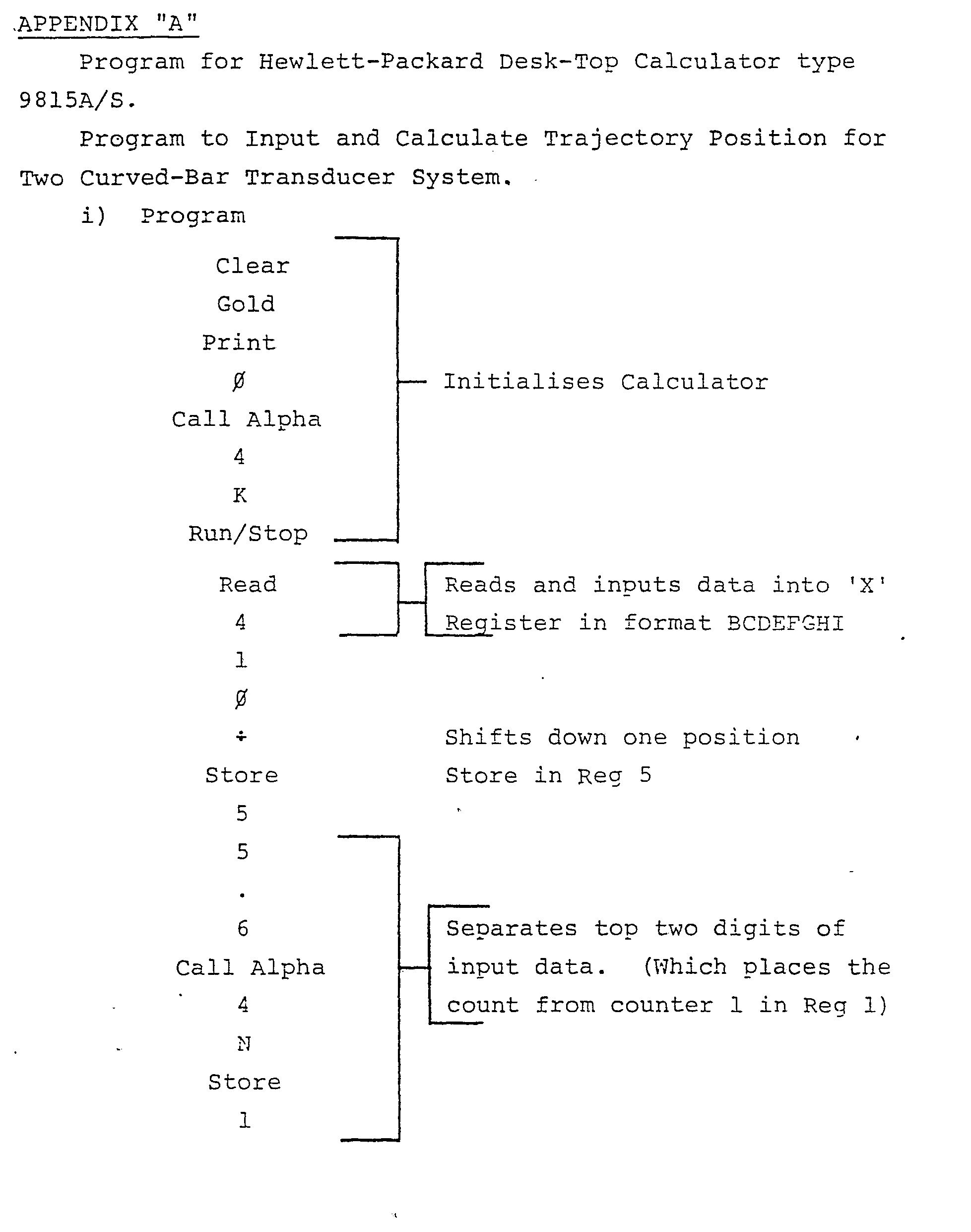


Claims (12)
Applications Claiming Priority (2)
| Application Number | Priority Date | Filing Date | Title |
|---|---|---|---|
| GB7916217 | 1979-05-10 | ||
| GB7916217 | 1979-05-10 |
Publications (2)
| Publication Number | Publication Date |
|---|---|
| EP0019428A1 true EP0019428A1 (en) | 1980-11-26 |
| EP0019428B1 EP0019428B1 (en) | 1983-02-09 |
Family
ID=10505062
Family Applications (1)
| Application Number | Title | Priority Date | Filing Date |
|---|---|---|---|
| EP80301517A Expired EP0019428B1 (en) | 1979-05-10 | 1980-05-09 | Projectile locating apparatus |
Country Status (3)
| Country | Link |
|---|---|
| US (1) | US4351026A (en) |
| EP (1) | EP0019428B1 (en) |
| DE (1) | DE3061871D1 (en) |
Cited By (5)
| Publication number | Priority date | Publication date | Assignee | Title |
|---|---|---|---|---|
| EP0064477A1 (en) * | 1981-04-23 | 1982-11-10 | Niklaus Loeliger | Method and assembly to locate detonations |
| EP0123043A1 (en) * | 1983-04-20 | 1984-10-31 | International Business Machines Corporation | Velocity sensing cursor control device and method |
| DE3433146A1 (en) * | 1984-09-10 | 1986-03-20 | Honeywell Gmbh, 6050 Offenbach | MEASURING AND SEARCH SYSTEM |
| WO1987005706A1 (en) * | 1986-03-12 | 1987-09-24 | Ms Instruments Plc | Position measuring apparatus and method |
| US6563763B2 (en) * | 2001-04-03 | 2003-05-13 | Aai Corporation | Method and system for correcting for curvature in determining the trajectory of a projectile |
Families Citing this family (16)
| Publication number | Priority date | Publication date | Assignee | Title |
|---|---|---|---|---|
| US4505481A (en) * | 1982-07-06 | 1985-03-19 | Australasian Training Aids (Pty.) Ltd. | Inflatable target apparatus |
| US4662845A (en) * | 1985-09-27 | 1987-05-05 | Loral Electro-Optical Systems, Inc. | Target system for laser marksmanship training devices |
| US5025424A (en) * | 1990-05-21 | 1991-06-18 | Rohrbaugh George W | Shock wave scoring apparatus employing curved rod sensors |
| US5095433A (en) * | 1990-08-01 | 1992-03-10 | Coyote Manufacturing, Inc. | Target reporting system |
| US5220160A (en) * | 1991-12-20 | 1993-06-15 | Cornell Research Foundation, Inc. | Adaptive fiber optic shock wave sensor |
| US5241518A (en) * | 1992-02-18 | 1993-08-31 | Aai Corporation | Methods and apparatus for determining the trajectory of a supersonic projectile |
| TW214006B (en) * | 1992-07-06 | 1993-10-01 | E Newgarden Joseph | An electronic table tennis game |
| IL118846A (en) * | 1996-07-14 | 2000-07-16 | Levanon Nadav | Method and apparatus for acoustic monitoring of the trajectory of a supersonic projectile |
| US5944317A (en) * | 1997-07-07 | 1999-08-31 | Rohrbaugh; George Wilson | Shock wave scoring apparatus employing dual concentric curved rod sensors |
| US6669477B2 (en) * | 2001-04-20 | 2003-12-30 | The United States Of America As Represented By The Secretary Of The Navy | System and method for scoring supersonic aerial projectiles |
| US6655190B2 (en) * | 2001-11-30 | 2003-12-02 | Honeywell International Inc. | Fixed beam high-g shock pulse generator apparatus and method |
| US9759530B2 (en) | 2014-03-06 | 2017-09-12 | Brian D. Miller | Target impact sensor transmitter receiver system |
| US10458758B2 (en) | 2015-01-20 | 2019-10-29 | Brian D. Miller | Electronic audible feedback bullet targeting system |
| US10712133B2 (en) * | 2017-08-01 | 2020-07-14 | nTwined LLC | Impact indication system |
| US11813537B2 (en) * | 2021-07-09 | 2023-11-14 | Gel Blaster, Inc. | Smart target co-witnessing hit attribution system and method |
| IL295152A (en) | 2022-07-27 | 2024-02-01 | Synchrosense Ltd | Compact supersonic projectile tracking |
Citations (5)
| Publication number | Priority date | Publication date | Assignee | Title |
|---|---|---|---|---|
| DE1566858B1 (en) * | 1967-11-21 | 1970-09-24 | Krupp Gmbh | Sound receiver in the form of a hollow cylinder |
| GB1371173A (en) * | 1973-01-19 | 1974-10-23 | Ms Instr Ltd | Coordinate measuring apparatus |
| DE2738213A1 (en) * | 1977-02-03 | 1978-07-27 | Hansrudolf Walti | DEVICE FOR INDEPENDENT ELECTRONIC DETERMINATION AND DISPLAY OF THE LOCATION OF HIT ON A SHOOTING TARGET |
| FR2381271A1 (en) * | 1977-02-21 | 1978-09-15 | Australasian Training Aids Pty | ELECTRONIC CONTROL DEVICES FOR A SHOOTING STAND |
| GB1553251A (en) * | 1976-05-20 | 1979-09-26 | Ms Instr Ltd | Position determining system |
Family Cites Families (12)
| Publication number | Priority date | Publication date | Assignee | Title |
|---|---|---|---|---|
| US2535255A (en) * | 1945-05-23 | 1950-12-26 | Thomas G Barnes | Electrical system for locating a sound source |
| US2973964A (en) * | 1955-08-01 | 1961-03-07 | American Mach & Foundry | Impact indicating system |
| US2916289A (en) * | 1955-08-01 | 1959-12-08 | American Mach & Foundry | Impact indicating system |
| US2925582A (en) * | 1956-02-22 | 1960-02-16 | Oflice Nat D Etudes Et De Rech | Acoustical firing indicator |
| GB969926A (en) | 1961-12-12 | 1964-09-16 | E W Bliss England Ltd | Control system for a mechanical press |
| US3489413A (en) * | 1967-06-28 | 1970-01-13 | Morris L Groder | Target scoring system |
| US3627323A (en) * | 1969-09-25 | 1971-12-14 | Wyle Laboratories | Hit detection shock system |
| US3678495A (en) * | 1970-02-26 | 1972-07-18 | Technical Management Services | Target indicating system and method |
| US3778059A (en) * | 1970-03-13 | 1973-12-11 | Singer Co | Automatic gunnery shock wave scoring apparatus using metallic conductors as shock wave sensors |
| US3707699A (en) * | 1970-08-07 | 1972-12-26 | Del Mar Eng Lab | Remote scoring system for bombing or rocket range |
| US3857022A (en) * | 1973-11-15 | 1974-12-24 | Integrated Sciences Corp | Graphic input device |
| US3985024A (en) * | 1975-02-28 | 1976-10-12 | Grumman Corporation | Acoustic emission process and system for improved flaw source location |
-
1980
- 1980-05-09 EP EP80301517A patent/EP0019428B1/en not_active Expired
- 1980-05-09 DE DE8080301517T patent/DE3061871D1/en not_active Expired
- 1980-05-09 US US06/148,570 patent/US4351026A/en not_active Expired - Lifetime
Patent Citations (5)
| Publication number | Priority date | Publication date | Assignee | Title |
|---|---|---|---|---|
| DE1566858B1 (en) * | 1967-11-21 | 1970-09-24 | Krupp Gmbh | Sound receiver in the form of a hollow cylinder |
| GB1371173A (en) * | 1973-01-19 | 1974-10-23 | Ms Instr Ltd | Coordinate measuring apparatus |
| GB1553251A (en) * | 1976-05-20 | 1979-09-26 | Ms Instr Ltd | Position determining system |
| DE2738213A1 (en) * | 1977-02-03 | 1978-07-27 | Hansrudolf Walti | DEVICE FOR INDEPENDENT ELECTRONIC DETERMINATION AND DISPLAY OF THE LOCATION OF HIT ON A SHOOTING TARGET |
| FR2381271A1 (en) * | 1977-02-21 | 1978-09-15 | Australasian Training Aids Pty | ELECTRONIC CONTROL DEVICES FOR A SHOOTING STAND |
Non-Patent Citations (1)
| Title |
|---|
| IEEE TRANSACTIONS ON POWER APPARATUS AND SYSTEMS, Vol. PAS-98, Nr. 2, March/April 1979 New York (US) R.T. HARROLD: "Acoustic waveguides for sensing and locating electrical discharges in high voltage power transformers and other apparatus", pages 449-455 * Page 453, right-hand column, line 18 to page 454, right-hand column, line 28; figure 7 * * |
Cited By (6)
| Publication number | Priority date | Publication date | Assignee | Title |
|---|---|---|---|---|
| EP0064477A1 (en) * | 1981-04-23 | 1982-11-10 | Niklaus Loeliger | Method and assembly to locate detonations |
| EP0123043A1 (en) * | 1983-04-20 | 1984-10-31 | International Business Machines Corporation | Velocity sensing cursor control device and method |
| US4578674A (en) * | 1983-04-20 | 1986-03-25 | International Business Machines Corporation | Method and apparatus for wireless cursor position control |
| DE3433146A1 (en) * | 1984-09-10 | 1986-03-20 | Honeywell Gmbh, 6050 Offenbach | MEASURING AND SEARCH SYSTEM |
| WO1987005706A1 (en) * | 1986-03-12 | 1987-09-24 | Ms Instruments Plc | Position measuring apparatus and method |
| US6563763B2 (en) * | 2001-04-03 | 2003-05-13 | Aai Corporation | Method and system for correcting for curvature in determining the trajectory of a projectile |
Also Published As
| Publication number | Publication date |
|---|---|
| EP0019428B1 (en) | 1983-02-09 |
| DE3061871D1 (en) | 1983-03-17 |
| US4351026A (en) | 1982-09-21 |
Similar Documents
| Publication | Publication Date | Title |
|---|---|---|
| EP0019428B1 (en) | Projectile locating apparatus | |
| EP0012580B1 (en) | Apparatus for detecting and locating the position of a bullet | |
| US4282453A (en) | Transducer apparatus for detecting airborne pressure pulse | |
| CA1147364A (en) | Discriminatory hit detection in target apparatus | |
| US4261579A (en) | Shock wave triggered target indicating system | |
| US6367800B1 (en) | Projectile impact location determination system and method | |
| EP0259428B1 (en) | Position measuring apparatus and method | |
| US7408840B2 (en) | System and method for disambiguating shooter locations | |
| KR100252523B1 (en) | Emergency root decision method and device of projector | |
| US20030008265A1 (en) | Time-difference process and apparatus for scoring supersonic aerial projectiles | |
| US6198694B1 (en) | Method and device for projectile measurements | |
| EP0003095B1 (en) | Indicator apparatus for determining a distance of a supersonic projectile in relation to a target | |
| KR100658004B1 (en) | Method and system for correcting for curvature in determining the trajectory of a projectile | |
| US5025424A (en) | Shock wave scoring apparatus employing curved rod sensors | |
| US3707699A (en) | Remote scoring system for bombing or rocket range | |
| US11231256B2 (en) | Method for manufacturing a device for locating an impact having at least three transducers attached against an interactive surface | |
| US5944317A (en) | Shock wave scoring apparatus employing dual concentric curved rod sensors | |
| GB2083177A (en) | Improvements in or relating to position determining apparatus | |
| CA1160260A (en) | Projectile position detection apparatus | |
| CA1147367A (en) | Hit detection and ricochet discrimination in target apparatus | |
| CA1147365A (en) | Physical hit detection system in target apparatus | |
| GB2120760A (en) | Marksmanship training apparatus | |
| AU611701B2 (en) | Markmanship training apparatus |
Legal Events
| Date | Code | Title | Description |
|---|---|---|---|
| PUAI | Public reference made under article 153(3) epc to a published international application that has entered the european phase |
Free format text: ORIGINAL CODE: 0009012 |
|
| AK | Designated contracting states |
Designated state(s): CH DE GB SE |
|
| 17P | Request for examination filed |
Effective date: 19801213 |
|
| GRAA | (expected) grant |
Free format text: ORIGINAL CODE: 0009210 |
|
| AK | Designated contracting states |
Designated state(s): CH DE GB LI SE |
|
| REF | Corresponds to: |
Ref document number: 3061871 Country of ref document: DE Date of ref document: 19830317 |
|
| REG | Reference to a national code |
Ref country code: GB Ref legal event code: 732 |
|
| REG | Reference to a national code |
Ref country code: GB Ref legal event code: 732 |
|
| REG | Reference to a national code |
Ref country code: CH Ref legal event code: PUE Owner name: ATA TRAINING AIDS AUST. PTY LIMITED TRANSFER- HYNT |
|
| REG | Reference to a national code |
Ref country code: CH Ref legal event code: PUE Owner name: AUSTRALIAN DEFENCE INDUSTRIES LIMITED |
|
| REG | Reference to a national code |
Ref country code: GB Ref legal event code: 732 |
|
| PGFP | Annual fee paid to national office [announced via postgrant information from national office to epo] |
Ref country code: GB Payment date: 19930428 Year of fee payment: 14 |
|
| PGFP | Annual fee paid to national office [announced via postgrant information from national office to epo] |
Ref country code: SE Payment date: 19930517 Year of fee payment: 14 Ref country code: CH Payment date: 19930517 Year of fee payment: 14 |
|
| PGFP | Annual fee paid to national office [announced via postgrant information from national office to epo] |
Ref country code: DE Payment date: 19930524 Year of fee payment: 14 |
|
| PG25 | Lapsed in a contracting state [announced via postgrant information from national office to epo] |
Ref country code: GB Effective date: 19940509 |
|
| PG25 | Lapsed in a contracting state [announced via postgrant information from national office to epo] |
Ref country code: SE Effective date: 19940510 |
|
| PG25 | Lapsed in a contracting state [announced via postgrant information from national office to epo] |
Ref country code: LI Effective date: 19940531 Ref country code: CH Effective date: 19940531 |
|
| GBPC | Gb: european patent ceased through non-payment of renewal fee |
Effective date: 19940509 |
|
| EUG | Se: european patent has lapsed |
Ref document number: 80301517.1 Effective date: 19941210 |
|
| REG | Reference to a national code |
Ref country code: CH Ref legal event code: PL |
|
| PG25 | Lapsed in a contracting state [announced via postgrant information from national office to epo] |
Ref country code: DE Effective date: 19950201 |
|
| EUG | Se: european patent has lapsed |
Ref document number: 80301517.1 |
|
| PLBE | No opposition filed within time limit |
Free format text: ORIGINAL CODE: 0009261 |
|
| STAA | Information on the status of an ep patent application or granted ep patent |
Free format text: STATUS: NO OPPOSITION FILED WITHIN TIME LIMIT |