EP0009303A1 - Adjustable lamps - Google Patents
Adjustable lamps Download PDFInfo
- Publication number
- EP0009303A1 EP0009303A1 EP79301324A EP79301324A EP0009303A1 EP 0009303 A1 EP0009303 A1 EP 0009303A1 EP 79301324 A EP79301324 A EP 79301324A EP 79301324 A EP79301324 A EP 79301324A EP 0009303 A1 EP0009303 A1 EP 0009303A1
- Authority
- EP
- European Patent Office
- Prior art keywords
- arm
- link
- lamp
- base
- pivoted
- Prior art date
- Legal status (The legal status is an assumption and is not a legal conclusion. Google has not performed a legal analysis and makes no representation as to the accuracy of the status listed.)
- Granted
Links
Images
Classifications
-
- F—MECHANICAL ENGINEERING; LIGHTING; HEATING; WEAPONS; BLASTING
- F21—LIGHTING
- F21S—NON-PORTABLE LIGHTING DEVICES; SYSTEMS THEREOF; VEHICLE LIGHTING DEVICES SPECIALLY ADAPTED FOR VEHICLE EXTERIORS
- F21S6/00—Lighting devices intended to be free-standing
- F21S6/002—Table lamps, e.g. for ambient lighting
- F21S6/003—Table lamps, e.g. for ambient lighting for task lighting, e.g. for reading or desk work, e.g. angle poise lamps
-
- F—MECHANICAL ENGINEERING; LIGHTING; HEATING; WEAPONS; BLASTING
- F21—LIGHTING
- F21V—FUNCTIONAL FEATURES OR DETAILS OF LIGHTING DEVICES OR SYSTEMS THEREOF; STRUCTURAL COMBINATIONS OF LIGHTING DEVICES WITH OTHER ARTICLES, NOT OTHERWISE PROVIDED FOR
- F21V21/00—Supporting, suspending, or attaching arrangements for lighting devices; Hand grips
- F21V21/14—Adjustable mountings
- F21V21/26—Pivoted arms
Definitions
- This invention relates to adjustable lamps.
- One well-known desk lamp comprises a heavy base, for stability, and which is intended to stand on a desk, table or the like (or alternatively the base may comprise a bracket or clamp which is intended to be fixed to a wall or other surface).
- a fork is connected to the base, a first arm is pivoted to the fork, a second arm is pivoted to the first arm, and the lamp housing (for example the shade or reflector and the bulb holder) is pivoted to the second arm.
- the first arm comprises an elongated parallelogram; the adjacent end of the second arm forms a first short side of this parallelogram, and a set of springs is used to couple the parallelogram at the second of its short sides to the fork.
- This complex arrangement is intended to enable the height of the lamp shade or like to be adjusted relative to the base by a mere touch on the shade or arm, and so that the adjusted height will remain unaltered until a further adjustment is required, without involving the use of separate locking devices.
- the arrangement works reasonably well although the lamp can be adjusted to positions where it is not in equilibrium, i.e. when the lamp will move from the adjusted position.
- a lamp comprises a base, an arm pivoted on the base and carrying a lamp housing at its free end, and a link also pivoted to the 00 base and making sliding frictional connection with the arm so that the pivot points of the arm and link together with the connection point at the link and arm form the apices of a triangle.
- the frictional resistance to sliding of the link connection on the arm is adjustable, and this may be particularly valuable if the base is to be either a weighted but free standing one, or a wall bracket, table clamp or other fixed mounting, since the loading which can be applied by a user in adjusting the lamp is much greater in the latter case and additional frictional resistance may be desirable.
- the link or the arm is spring urged to resist movement of the parts taking the arm towards the horizontal.
- the spring may be arranged to become effective only when the angle reduces below a predetermined value which may be the maximum angle likely in normal use of the lamp.
- the lamp comprises a free standing heavy base generally indicated by the reference numeral 10, an arm 12, which may be of square cross section tube which is pivoted at its lower end upon a pin 14 to the base, and is hingedly connected at 16 to a lamp housing 18 which comprises a shade or reflector, a bulb holder and an on/off switch 20 for the lamp.
- the electric conductor wires may be led through passages 20 22 in the base (Fig.4) along the interior of the arm 12, through the hinge joint 16 and into the housing 18, so that they are not exposed to view and incidentally are protected against accidental damage.
- the principle adjustment of the lamp is to vary the angle of the arm 12 between a near horizontal and near vertical position, thus varying the height of the housing 18 above the notional surface on which the base 10 rests. Additionally, the lamp housing 18 may be turned by means of the hinge, usually so as to keep the housing generally parallel to the table or desk top on which the base 10 stands, but sometimes it may be desired to turn the lamp to non-parallel positions.
- a link 24 is provided which is pivoted on a pin 26 in the base and is at opposite end on pin 28 to a frictional sliding connector block 30.
- the latter is threaded by the arm 12, and it will be appreciated that in angular adjustment of arm 12 the block 30 slides along the length of the arm and offers a frictional resistance to the sliding, tending to hold the block and the link in any selected position and thus enable the lamp to regain in any particular adjusted position selected by the user.
- the block 30 may be made of any suitable plastics material, and the dimensions of the aperture through which the arm 12 extends are carefully selected to provide the required frictional resistance to sliding. However, in order to provide a substantially constant frictional resistance after a certain amount of wear has taken place, or whilst allowing substantial manufacturing tolerances or for other reasons, an adjuster screw 32 is provided engaged with a screwthreaded bore in the block 30, and a friction pad 34 seats against the arm with a spring 36 interposed between the latter and the screw. This has the further advantage of allowing the degree of frictional resistance to be varied, for example in the event that a clamp type base is provided instead of the weighted base illustrated, since the user may then apply substantially greater loading to the arm in adjustment movements without the risk of the base moving.
- Pin 26 extends through a bush 38 which forms a support for a torsion spring 40, the spring having tails 42 which abut a surface in the base part which journals the pin and bush, and the spring also having a bridge 44 to abut the link.
- the effect is that when the arm 12 moves frorr a near vertical position, clockwise about its pivot 14 in Figure 4, the link 24 moves towards a vertical position (also anticlockwise about its pin 26) until the link abuts the bridge 44. Up to this point there is no spring loading effective.
- the link displaces the bridge 44 in the same anticlockwise direction, and because the torsion spring cannot turn as a whole owing to the abutment of the tails 42 with the base part, the spring is wound up and stressed as the arm movement continues, and the nearer the arm 12 approaches to the horizontal, the greater the spring loading on the link.
- This can more or less provide a counterbalance for the increasing turning moment caused by the weight of the lamp housing as it moves horizontally further from the pivot 14.
Abstract
Description
- This invention relates to adjustable lamps.
- One well-known desk lamp comprises a heavy base, for stability, and which is intended to stand on a desk, table or the like (or alternatively the base may comprise a bracket or clamp which is intended to be fixed to a wall or other surface). A fork is connected to the base, a first arm is pivoted to the fork, a second arm is pivoted to the first arm, and the lamp housing (for example the shade or reflector and the bulb holder) is pivoted to the second arm. In this construction the first arm comprises an elongated parallelogram; the adjacent end of the second arm forms a first short side of this parallelogram, and a set of springs is used to couple the parallelogram at the second of its short sides to the fork. This complex arrangement is intended to enable the height of the lamp shade or like to be adjusted relative to the base by a mere touch on the shade or arm, and so that the adjusted height will remain unaltered until a further adjustment is required, without involving the use of separate locking devices. In practice the arrangement works reasonably well although the lamp can be adjusted to positions where it is not in equilibrium, i.e. when the lamp will move from the adjusted position.
- It is an object of the invention to produce a construction of like effect, but using fewer parts so as to be not only cheaper to manufacture but also aesthetically improved.
- In accordance with the invention a lamp comprises a base, an arm pivoted on the base and carrying a lamp housing at its free end, and a link also pivoted to the 00 base and making sliding frictional connection with the arm so that the pivot points of the arm and link together with the connection point at the link and arm form the apices of a triangle.
- Preferably the frictional resistance to sliding of the link connection on the arm is adjustable, and this may be particularly valuable if the base is to be either a weighted but free standing one, or a wall bracket, table clamp or other fixed mounting, since the loading which can be applied by a user in adjusting the lamp is much greater in the latter case and additional frictional resistance may be desirable.
- Preferably also the link or the arm is spring urged to resist movement of the parts taking the arm towards the horizontal. When the arm is vertical, there is little turning moment due to the lamp housing, but as the angle of inclination of the arm reduces, the turning moment increases. The spring may be arranged to become effective only when the angle reduces below a predetermined value which may be the maximum angle likely in normal use of the lamp.
- One presently preferred embodiment of the invention is now more particularly described with reference to the accompanying drawings wherein:-
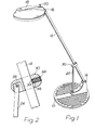
- Figure 1 is a perspective view of a complete lamp;
- Figure 2 is a fragmentary sectional elevation showing the sliding frictional connection of the arm and link of the same;
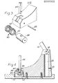
- Figure 3 is a fragmentary exploded perspective view showing the parts providing spring loading for the link at the base; and
- Figure 4 is a fragmentary sectional elevation of the base.
- Referring first to Figure 1, the lamp comprises a free standing heavy base generally indicated by the
reference numeral 10, anarm 12, which may be of square cross section tube which is pivoted at its lower end upon apin 14 to the base, and is hingedly connected at 16 to alamp housing 18 which comprises a shade or reflector, a bulb holder and an on/offswitch 20 for the lamp. - The electric conductor wires may be led through
passages 20 22 in the base (Fig.4) along the interior of thearm 12, through thehinge joint 16 and into thehousing 18, so that they are not exposed to view and incidentally are protected against accidental damage. - The principle adjustment of the lamp is to vary the angle of the
arm 12 between a near horizontal and near vertical position, thus varying the height of thehousing 18 above the notional surface on which thebase 10 rests. Additionally, thelamp housing 18 may be turned by means of the hinge, usually so as to keep the housing generally parallel to the table or desk top on which thebase 10 stands, but sometimes it may be desired to turn the lamp to non-parallel positions. - To hold the
arm 12 in any selected angle, alink 24 is provided which is pivoted on apin 26 in the base and is at opposite end onpin 28 to a frictionalsliding connector block 30. The latter is threaded by thearm 12, and it will be appreciated that in angular adjustment ofarm 12 theblock 30 slides along the length of the arm and offers a frictional resistance to the sliding, tending to hold the block and the link in any selected position and thus enable the lamp to regain in any particular adjusted position selected by the user. - The
block 30 may be made of any suitable plastics material, and the dimensions of the aperture through which thearm 12 extends are carefully selected to provide the required frictional resistance to sliding. However, in order to provide a substantially constant frictional resistance after a certain amount of wear has taken place, or whilst allowing substantial manufacturing tolerances or for other reasons, anadjuster screw 32 is provided engaged with a screwthreaded bore in theblock 30, and afriction pad 34 seats against the arm with aspring 36 interposed between the latter and the screw. This has the further advantage of allowing the degree of frictional resistance to be varied, for example in the event that a clamp type base is provided instead of the weighted base illustrated, since the user may then apply substantially greater loading to the arm in adjustment movements without the risk of the base moving. -
Pin 26 extends through abush 38 which forms a support for atorsion spring 40, thespring having tails 42 which abut a surface in the base part which journals the pin and bush, and the spring also having abridge 44 to abut the link. The effect is that when thearm 12 moves frorr a near vertical position, clockwise about itspivot 14 in Figure 4, thelink 24 moves towards a vertical position (also anticlockwise about its pin 26) until the link abuts thebridge 44. Up to this point there is no spring loading effective. As the movement continues, the link displaces thebridge 44 in the same anticlockwise direction, and because the torsion spring cannot turn as a whole owing to the abutment of thetails 42 with the base part, the spring is wound up and stressed as the arm movement continues, and the nearer thearm 12 approaches to the horizontal, the greater the spring loading on the link. This can more or less provide a counterbalance for the increasing turning moment caused by the weight of the lamp housing as it moves horizontally further from thepivot 14. Ideally, it is possible to move thearm 12 in the said counterclockwise direction by a finger touch, and for the arm to remain in any adjusted position when the touch is released, and for the same to be possible in the clockwise direction of adjustment.
Claims (5)
Priority Applications (1)
| Application Number | Priority Date | Filing Date | Title |
|---|---|---|---|
| AT79301324T ATE759T1 (en) | 1978-08-26 | 1979-07-09 | ADJUSTABLE LAMP. |
Applications Claiming Priority (2)
| Application Number | Priority Date | Filing Date | Title |
|---|---|---|---|
| GB3478078 | 1978-08-26 | ||
| GB7834780 | 1978-08-26 |
Publications (2)
| Publication Number | Publication Date |
|---|---|
| EP0009303A1 true EP0009303A1 (en) | 1980-04-02 |
| EP0009303B1 EP0009303B1 (en) | 1982-03-17 |
Family
ID=10499309
Family Applications (1)
| Application Number | Title | Priority Date | Filing Date |
|---|---|---|---|
| EP79301324A Expired EP0009303B1 (en) | 1978-08-26 | 1979-07-09 | Adjustable lamps |
Country Status (6)
| Country | Link |
|---|---|
| US (1) | US4314319A (en) |
| EP (1) | EP0009303B1 (en) |
| JP (1) | JPS5532393A (en) |
| AT (1) | ATE759T1 (en) |
| AU (1) | AU524694B2 (en) |
| DE (1) | DE2962283D1 (en) |
Cited By (2)
| Publication number | Priority date | Publication date | Assignee | Title |
|---|---|---|---|---|
| US5108061A (en) * | 1988-06-17 | 1992-04-28 | Vlasak Miroslav J | Adjustable stand |
| DE202012012084U1 (en) | 2012-07-09 | 2013-04-15 | Schebo Biotech Ag | Test kit (combi rapid test) for the synchronous detection of biomarkers in stool for the detection of pathological changes in the gastrointestinal tract, especially in the intestine |
Families Citing this family (11)
| Publication number | Priority date | Publication date | Assignee | Title |
|---|---|---|---|---|
| JPS59195603U (en) * | 1983-06-14 | 1984-12-26 | 日本電気ホームエレクトロニクス株式会社 | lighting equipment |
| US4796172A (en) * | 1987-11-09 | 1989-01-03 | Chestnut H Gary | Portable light support apparatus and method of erecting and collapsing same |
| US4847740A (en) * | 1987-12-30 | 1989-07-11 | Laske Lawrence L | Adjustable lamp |
| US4928217A (en) * | 1987-12-30 | 1990-05-22 | Laske Lawrence L | Adjustable lamp |
| US4975818A (en) * | 1987-12-30 | 1990-12-04 | Laske Lawrence L | Adjustable lamp |
| US4827390A (en) * | 1987-12-30 | 1989-05-02 | Laske Lawrence L | Adjustable lamp |
| US5553820A (en) * | 1994-10-17 | 1996-09-10 | Rubbermaid Office Products Inc. | Adjustable monitor arm |
| FR2792996B1 (en) * | 1999-04-28 | 2001-07-13 | Alm | FLEXIBLE ANGULAR TRAVEL LIMIT STOP, ARTICULATED SYSTEM COMPRISING SUCH A STOP, AND MEDICAL EQUIPMENT COMPRISING SUCH AN ARTICULATED SYSTEM |
| US8584993B2 (en) * | 2004-03-11 | 2013-11-19 | The Aluminum Lighting Company Limited | Column and hinge assemblies therefor |
| US20140000063A1 (en) * | 2012-06-28 | 2014-01-02 | Hang-John Lin | Adjustable unit for table lamp |
| USD918455S1 (en) * | 2019-05-16 | 2021-05-04 | Beijing Xiaomi Mobile Software Co., Ltd. | Table lamp |
Citations (3)
| Publication number | Priority date | Publication date | Assignee | Title |
|---|---|---|---|---|
| GB636775A (en) * | 1943-06-07 | 1950-05-03 | Art Specialty Co | Improvements in adjustable supports for lamps or the like |
| US2608367A (en) * | 1950-04-26 | 1952-08-26 | Boltuch Leon | Adjustable support |
| FR2366511A1 (en) * | 1976-09-29 | 1978-04-28 | Blanzieri Renzo | Articulated linkage desk lamp - has friction shoes acting on one leg of quadrangular linkage to hold lamp in balance (NL 31.3.78) |
Family Cites Families (13)
| Publication number | Priority date | Publication date | Assignee | Title |
|---|---|---|---|---|
| US494116A (en) * | 1893-03-28 | Lamp-suspending device | ||
| US1025537A (en) * | 1911-07-26 | 1912-05-07 | Conrad M Pitel | Gas or electric light extension-fixture. |
| US2740039A (en) * | 1952-09-05 | 1956-03-27 | Phillips Louis | Vertically and angularly adjustable lamp |
| US3012798A (en) * | 1957-03-13 | 1961-12-12 | Berger Kornel | Universal electric swivel joint |
| US2910310A (en) * | 1957-12-06 | 1959-10-27 | Rudolph A Mulac | Ball and socket swivel for an electric light receptacle |
| GB1002839A (en) * | 1963-05-13 | 1965-09-02 | Eivind Kirkeby | A counterbalanced lamp stand |
| US3604916A (en) * | 1968-10-15 | 1971-09-14 | Hubbell Inc Harvey | Floodlight-mounting arrangement |
| GB1392605A (en) * | 1971-09-16 | 1975-04-30 | Oram J A | Adjustable articulated support |
| US3778610A (en) * | 1972-12-04 | 1973-12-11 | L Wolf | Adjustable joint for electrical fixtures |
| DE2627514C3 (en) * | 1976-06-18 | 1983-02-24 | W.C. Heraeus Gmbh, 6450 Hanau | Swivel joint |
| JPS5424622A (en) * | 1977-07-27 | 1979-02-24 | West Electric Co | Flash device for photography |
| IT1086170B (en) * | 1977-07-28 | 1985-05-28 | Iguzzini Spa | SUPPORT WITH ARTICULATED ARMS, IN PARTICULAR FOR LAMPS |
| GB1601246A (en) * | 1977-07-29 | 1981-10-28 | Bernardi S | Adjustable stands |
-
1979
- 1979-07-09 AT AT79301324T patent/ATE759T1/en not_active IP Right Cessation
- 1979-07-09 EP EP79301324A patent/EP0009303B1/en not_active Expired
- 1979-07-09 DE DE7979301324T patent/DE2962283D1/en not_active Expired
- 1979-07-12 US US06/056,964 patent/US4314319A/en not_active Expired - Lifetime
- 1979-07-17 AU AU49005/79A patent/AU524694B2/en not_active Ceased
- 1979-07-27 JP JP9597779A patent/JPS5532393A/en active Pending
Patent Citations (3)
| Publication number | Priority date | Publication date | Assignee | Title |
|---|---|---|---|---|
| GB636775A (en) * | 1943-06-07 | 1950-05-03 | Art Specialty Co | Improvements in adjustable supports for lamps or the like |
| US2608367A (en) * | 1950-04-26 | 1952-08-26 | Boltuch Leon | Adjustable support |
| FR2366511A1 (en) * | 1976-09-29 | 1978-04-28 | Blanzieri Renzo | Articulated linkage desk lamp - has friction shoes acting on one leg of quadrangular linkage to hold lamp in balance (NL 31.3.78) |
Cited By (2)
| Publication number | Priority date | Publication date | Assignee | Title |
|---|---|---|---|---|
| US5108061A (en) * | 1988-06-17 | 1992-04-28 | Vlasak Miroslav J | Adjustable stand |
| DE202012012084U1 (en) | 2012-07-09 | 2013-04-15 | Schebo Biotech Ag | Test kit (combi rapid test) for the synchronous detection of biomarkers in stool for the detection of pathological changes in the gastrointestinal tract, especially in the intestine |
Also Published As
| Publication number | Publication date |
|---|---|
| AU4900579A (en) | 1980-05-22 |
| AU524694B2 (en) | 1982-09-30 |
| DE2962283D1 (en) | 1982-04-15 |
| JPS5532393A (en) | 1980-03-07 |
| EP0009303B1 (en) | 1982-03-17 |
| US4314319A (en) | 1982-02-02 |
| ATE759T1 (en) | 1982-04-15 |
Similar Documents
| Publication | Publication Date | Title |
|---|---|---|
| EP0009303A1 (en) | Adjustable lamps | |
| US4568052A (en) | Apparatus for supporting an object in a desired position | |
| US5170975A (en) | Articulated arm with spring for counterbalancing | |
| US4621782A (en) | Arrangement for mounting apparatus | |
| US20040124328A1 (en) | Equipoise arm assembly | |
| US4266747A (en) | Equipoised articulated support arm | |
| US4744019A (en) | Counterbalanced arm assembly | |
| US5108061A (en) | Adjustable stand | |
| FI77105C (en) | STATIV SPECIELLT FOER BILDSKAERMSTERMINALER. | |
| US5222806A (en) | Lamp | |
| US4796162A (en) | Counterbalanced arm assembly | |
| GB1601246A (en) | Adjustable stands | |
| CA2098724A1 (en) | Cradle assembly for a moveable arm support system | |
| US1263783A (en) | Adjustable lamp-support. | |
| US4661895A (en) | Adjustable counterbalanced arm assembly for an electric lamp | |
| US3413459A (en) | Counterpoise lamp | |
| US3391890A (en) | Extensible, tiltable, counterbalanced lamp bracket | |
| US20140003069A1 (en) | Articulated lamp assembly with imbeded compression springs | |
| EP0612393A1 (en) | Adjustable support device | |
| US3409767A (en) | Adjustable lamp structure | |
| US1708047A (en) | Light fixture | |
| US3277292A (en) | Light wands | |
| AU596641B2 (en) | Tilt apparatus for a display monitor | |
| US4847740A (en) | Adjustable lamp | |
| CN1882873A (en) | Projector |
Legal Events
| Date | Code | Title | Description |
|---|---|---|---|
| PUAI | Public reference made under article 153(3) epc to a published international application that has entered the european phase |
Free format text: ORIGINAL CODE: 0009012 |
|
| AK | Designated contracting states |
Designated state(s): AT BE CH DE FR GB IT LU NL SE |
|
| 17P | Request for examination filed | ||
| ITF | It: translation for a ep patent filed |
Owner name: ING. A. GIAMBROCONO & C. S.R.L. |
|
| GRAA | (expected) grant |
Free format text: ORIGINAL CODE: 0009210 |
|
| TCAT | At: translation of patent claims filed | ||
| AK | Designated contracting states |
Designated state(s): AT BE CH DE FR GB IT LU NL SE |
|
| PG25 | Lapsed in a contracting state [announced via postgrant information from national office to epo] |
Ref country code: CH Effective date: 19820317 Ref country code: BE Effective date: 19820317 |
|
| REF | Corresponds to: |
Ref document number: 759 Country of ref document: AT Date of ref document: 19820415 Kind code of ref document: T |
|
| REF | Corresponds to: |
Ref document number: 2962283 Country of ref document: DE Date of ref document: 19820415 |
|
| PGFP | Annual fee paid to national office [announced via postgrant information from national office to epo] |
Ref country code: AT Payment date: 19820707 Year of fee payment: 4 |
|
| PGFP | Annual fee paid to national office [announced via postgrant information from national office to epo] |
Ref country code: FR Payment date: 19820715 Year of fee payment: 4 |
|
| REG | Reference to a national code |
Ref country code: CH Ref legal event code: PL |
|
| PG25 | Lapsed in a contracting state [announced via postgrant information from national office to epo] |
Ref country code: LU Free format text: LAPSE BECAUSE OF NON-PAYMENT OF DUE FEES Effective date: 19820731 |
|
| PGFP | Annual fee paid to national office [announced via postgrant information from national office to epo] |
Ref country code: NL Payment date: 19820731 Year of fee payment: 4 |
|
| PGFP | Annual fee paid to national office [announced via postgrant information from national office to epo] |
Ref country code: SE Payment date: 19820930 Year of fee payment: 4 Ref country code: DE Payment date: 19820930 Year of fee payment: 4 |
|
| PG25 | Lapsed in a contracting state [announced via postgrant information from national office to epo] |
Ref country code: AT Effective date: 19830709 |
|
| PG25 | Lapsed in a contracting state [announced via postgrant information from national office to epo] |
Ref country code: SE Free format text: THE PATENT HAS BEEN ANNULLED BY A DECISION OF A NATIONAL AUTHORITY Effective date: 19830730 |
|
| PG25 | Lapsed in a contracting state [announced via postgrant information from national office to epo] |
Ref country code: NL Effective date: 19840201 |
|
| PG25 | Lapsed in a contracting state [announced via postgrant information from national office to epo] |
Ref country code: FR Free format text: LAPSE BECAUSE OF NON-PAYMENT OF DUE FEES Effective date: 19840330 |
|
| PG25 | Lapsed in a contracting state [announced via postgrant information from national office to epo] |
Ref country code: DE Effective date: 19840403 |
|
| REG | Reference to a national code |
Ref country code: FR Ref legal event code: ST |
|
| GBPC | Gb: european patent ceased through non-payment of renewal fee | ||
| PG25 | Lapsed in a contracting state [announced via postgrant information from national office to epo] |
Ref country code: GB Effective date: 19881118 |
|
| EUG | Se: european patent has lapsed |
Ref document number: 79301324.4 Effective date: 19850610 |
|
| PLBE | No opposition filed within time limit |
Free format text: ORIGINAL CODE: 0009261 |
|
| STAA | Information on the status of an ep patent application or granted ep patent |
Free format text: STATUS: NO OPPOSITION FILED WITHIN TIME LIMIT |