EP0004657A2 - Method for tape recording time-spaced segments of video information and apparatus for carrying out this method - Google Patents
Method for tape recording time-spaced segments of video information and apparatus for carrying out this method Download PDFInfo
- Publication number
- EP0004657A2 EP0004657A2 EP79100997A EP79100997A EP0004657A2 EP 0004657 A2 EP0004657 A2 EP 0004657A2 EP 79100997 A EP79100997 A EP 79100997A EP 79100997 A EP79100997 A EP 79100997A EP 0004657 A2 EP0004657 A2 EP 0004657A2
- Authority
- EP
- European Patent Office
- Prior art keywords
- tape
- recording
- signal
- transport
- signals
- Prior art date
- Legal status (The legal status is an assumption and is not a legal conclusion. Google has not performed a legal analysis and makes no representation as to the accuracy of the status listed.)
- Granted
Links
Images

Classifications
-
- G—PHYSICS
- G11—INFORMATION STORAGE
- G11B—INFORMATION STORAGE BASED ON RELATIVE MOVEMENT BETWEEN RECORD CARRIER AND TRANSDUCER
- G11B27/00—Editing; Indexing; Addressing; Timing or synchronising; Monitoring; Measuring tape travel
- G11B27/02—Editing, e.g. varying the order of information signals recorded on, or reproduced from, record carriers
- G11B27/022—Electronic editing of analogue information signals, e.g. audio or video signals
- G11B27/028—Electronic editing of analogue information signals, e.g. audio or video signals with computer assistance
-
- G—PHYSICS
- G11—INFORMATION STORAGE
- G11B—INFORMATION STORAGE BASED ON RELATIVE MOVEMENT BETWEEN RECORD CARRIER AND TRANSDUCER
- G11B2220/00—Record carriers by type
- G11B2220/90—Tape-like record carriers
Definitions
- the invention relates to methods, arrangements and systems for recording video signals in longitudinal tracks of a magnetic tape in a tape recorder, with scenes separated in time and consisting of video signals from a video signal source being recorded and reproduced without any spacing between them and without synchronization errors.
- a video tape recorder is used to record television programs, it usually runs in the recording mode for comparatively long, uninterrupted periods of time. In addition, a tape recorder used for recording television programs will rarely operate in playback mode such that two or more recorded program segments are played back without stopping the tape. If, on the other hand, the video tape device is used with a video camera, that is to say in "home theater" mode, the tape device is frequently started and stopped, and the length of the recorded scene will normally be only a few seconds.
- Tape drives such as those used in video tape recorders, require a relatively long period of time to accelerate the tape to recording speed and to delay the tape when recording stops. If the tape was only delayed at the end of the recording of one scene and accelerated again at the beginning of the recording of the next scene, the line and image synchronization signals recorded on the tape with the video information would be distributed unevenly over the tape. Even if the recording were suppressed during tape acceleration and deceleration, there would inevitably be significant unevenness in the sequence of the synchronization pulses. If such a tape is played back at full speed, the synchronization in the reproduced picture is temporarily lost and consequently a "scrolling through" occurs with every scene change. When the scenes are only about a few seconds long, the frequent synchronization errors and losses are perceived by the viewer as a source of disturbance and annoyance.
- the object of the present invention is to provide methods, arrangements and a system for video tape recording, whereby the synchronization between successive scenes of the recording is maintained without having to accept a long delay before the recording of each scene can begin .
- the invention relates to a method, suitable arrangements and a system for recording successive, time-separated scenes in a video tape recorder with longitudinal track recording.
- the tape runs past a stationary recording / reproducing head at a relatively high speed and not at a comparatively slower tape transport speed due to the very fast rotation of one or more heads in a helical track tape device.
- the method of the invention comprises the steps of delaying the tape to a standstill after recording of a first scene in an original tape transport direction, accelerating the tape in the opposite direction until the desired recording speed of the tape transport is reached at a relatively high speed in the opposite direction within a certain period of time and the band retarding to a standstill.
- the tape transport accelerates in the original direction until the desired recording speed of the tape has been reached and synchronization pulses are read from the tape and to it used to synchronize the operation of a video signal source, in particular a video camera, before the tape device is again switched to the recording mode.
- the steps of accelerating the tape up to the recording speed and latching onto the synchronizing signals reproduced by the tape take only a few 100 milliseconds. This delay is hardly noticed by the user of the system and the loss of information from switching on the camera until the actual recording process begins is kept very small.
- a camera is used as the video signal source and that the above-mentioned synchronization step comprises the synchronization of the horizontal synchronizing pulses read from the tape with the horizontal synchronizing pulses which are used to operate the camera and that the vertical synchronization of the camera is adjusted in this way will match the vertical sync signals read from the tape.
- the method of the invention comprises the steps of determining whether the camera has just been turned off at the end of a scene and, if so, waiting for the next vertical sync pulse on the tape, switching to playback mode, and delaying the tape to a standstill. This is followed by the steps of resetting the tape, accelerating the tape in a direction opposite to the original recording direction, waiting for a predetermined period of time to elapse and delaying the tape again to a standstill.
- the method further includes the steps of determining whether the camera has just been turned on to record a new scene and, if so, accelerating the tape to record speed, synchronizing the tape transport for the horizontal sync pulses read from the tape, waiting for at least one vertical sync pulse, and, at Detection of such a vertical synchronization pulse, readjustment of the camera synchronization and switching to the recording mode.
- Motor speed control devices to regulate the motor and belt speed depending on an oscillator signal
- Synchronization devices for synchronizing the tape transport set via the synchronization signals received from the tape with the synchronization signals of the signal source
- Switching devices which are controlled by the device control devices, for switching to the recording mode when the tape transport is fully synchronized with the signal source.
- the arrangement includes means for stopping and resetting the tape after the camera is turned off at the end of a scene, means for accelerating the tape to recording speed after actuation of the camera for recording the next scene, and synchronizing means for synchronizing the recording system and the camera with Tape read synchronization signals before the video tape recorder switches to recording mode and the next scene is recorded.
- the video signals to be recorded are generated by a video camera and the synchronization devices contain the following units: a comparison circuit for comparing the horizontal synchronization signals obtained from the tape with the horizontal synchronization signals L J generated by an independent reference frequency and used for camera control and adjusting devices which adjust the vertical synchronization of the camera when a vertical synchronizing signal is scanned from the tape.
- the engine speed control devices can contain a feedback circuit which has a tachometer coupled to the engine, a phase comparator for comparing the oscillator signal with a signal generated by the tachometer and for generating a difference signal, and an engine control stage for controlling the engine speed as a function of the Difference signal includes.
- the oscillator signal supplied to the phase comparator can be supplied by the device control device and the oscillator signal can be derived from a reference frequency in the recording mode and from the comparison circuit for the horizontal synchronization signals in the playback mode.
- the comparison circuit for the horizontal synchronization signals can contain a second phase comparator which provides a difference signal from the phase comparison, and a variable oscillator can be provided for generating an oscillator signal which is partly dependent on the latter difference signal.
- the present invention provides a video recording system in which synchronization between successively recorded but originally temporally separated scenes is achieved without the need to precede the recording of each scene with a more than absolutely necessary long delay time.
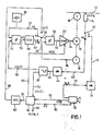
- FIG. 1 is a basic circuit diagram in a simplified representation, which shows an arrangement according to the invention with parts of a video tape recorder for longitudinal track recording in connection with a video camera,
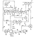
- Figure 2 is a tape speed / Bandlagediagr _ mm, which according to the invention illustrates the tape transport and the "diagram" is a flow diagram which shows the sequence of the measures and functions carried out according to the invention, in particular the functions of the device control device according to FIG. 1.
- a method for recording multiple, time-separated sequences of scenes in a video tape recording system is described, with which the scenes can be recorded in a row without any synchronization errors or losses being reproduced.
- This goal is achieved in a recording device with longitudinal track recording firstly by resetting the tape at the end of each recorded scene and secondly before the start of the recording of the next scene, by an extremely fast synchronization operation of the recording system with the synchronization signals obtained from the tape.
- the tape moves relatively quickly with respect to a recording / reproducing head and not at a much slower speed past one or more rapidly rotating transducers as in helical scan devices.
- To on one Longitudinal track tape to achieve a sufficiently long recording time is usually a number of several longitudinal recording tracks distributed over the bandwidth.
- the direction of tape transport is reversed and the recording head is switched accordingly to a new track position.
- such a longitudinal track recording tape system contains a drive roller (C), reference number 10, which guides a tape 12, in particular a magnetic tape, past a recording / playback head (R / PB), 14.
- C drive roller
- R / PB recording / playback head
- the drive roller 10 is mechanically coupled to a drive motor 16 (M), to which a tachometer 18 (T) is also connected for precisely determining the engine speed.
- the speed of the tape 12 with respect to the transducer head 14 is precisely controlled, both during the recording and during the playback of the video information.
- a number of different methods can be used to control the speed of motor 16, but for purposes of illustration, the motor is controlled primarily via a servo loop that includes a tachometer 18, a phase comparator 20, and a control amplifier 22 for the motor.
- the tachometer 18 generates pulses with line frequency (f R ) when the tape is transported at the desired speed. These pulses are fed via line 24 to an input of phase comparator 20, while the other input on line 26 receives a signal corresponding to the reference frequency.
- the output of the phase comparator 20 is connected via line 32 to the control amplifier 22 for the motor, the output of which is fed to the motor 16 via line 34 is. It can be seen that when a phase difference is detected between the pulses (line 24) generated by the tachometer 18 and the pulses supplied via line 26 at reference frequency (fR), the phase comparator 20 generates a difference signal which is used to control the motor 22 via the control amplifier 22 to control faster or slower until the occurring phase difference becomes zero.
- the control loop with the tachometer 18 thus causes the engine speed to lock onto the reference frequency supplied on line 26.
- line 26 is connected to the movable contact pole of a three-way switch 36 which has a "record” (R) position, a “play” (? B) position and an acceleration-deceleration (A / D) position can take.
- the switch 18 connects the line 26 to the line 37, on which a reference signal (f R ) with the desired line frequency (f R ) is supplied, which comes from a quartz-controlled pulse generator 38.
- the tape speed is locked with the reference frequency via the control loop mentioned above.
- an additional control loop is effective in order to synchronize the motor 16 with the synchronizing signals sampled from the tape 12. More specifically, the horizontal synchronizing signals are sampled from the tape 12 by means of the recording / reproducing head 14 which is connected to the movable contact pole of a single-pole switch 40 which has a recording and a replay. position (R or PB). In the playback position PB, the signal from the transducer head 14 is applied via line 42 to a demodulator 44, where it is demodulated, so that a baseband video signal mixture is obtained on its output line 46.
- Via line 46 is the baseband signal to a conventional Tm p 48 supplied ulsabtrenner which separates the baseband signal, the horizontal and vertical synchronizing signals HS (T) or VS (T), with the former, HS (T), and the latter on line 50, VS (T ), are delivered on line 52.
- the horizontal synchronization signals HS (T) of line 50 are fed to a second phase comparator 54, the other input of which receives the reference signal supplied by pulse generator 38 on line 37.
- the second phase comparator 54 generates a differential signal or error signal (ES) on line 55, which is used to control the frequency of a voltage-dependent oscillator 56, the oscillator output being connected via line 57 to the playback contact (PB) of the three-way switch 36.
- ES differential signal or error signal
- the synchronizing signals derived from the tape are compared with the reference frequency signals in the phase comparator 54 and the voltage dependent oscillator 56 generates pulses of suitable Freuqenz to the tape transport via the motor in synchronism with theachessfre- q uence (f R) of the line to drive 37th
- the reference signal on line 26 is supplied via line 58 from the device control device 60.
- the frequency of this signal can be varied in the control device 60, as is made clear by the frequency-variable oscillator 62 (VFO), which is connected via the line 64.
- variable frequency reference signals on line 58 which are necessary for the controlled acceleration and deceleration of band 12, can be generated by one of many known methods.
- a ramp-shaped acceleration signal with increasing frequency can be processed in the device 60 itself, and not by means of the external oscillator 62.
- the circuitry in Figure 1 does not show any time base correction circuits that may be required to compensate for tape speed fluctuations that can be caused by variations in tape tension or other factors, such as irregularities in the tape transport device.
- the control device 60 In addition to the signals on line 64, which are essentially speed control signals, the control device 60 also generates an engine control signal (MDC) on line 66 which leads to the control amplifier 22 and receives vertical synchronizing signals from the pulse separator 48 via line 52.
- MDC engine control signal
- a video camera 70 generates both video and optional audio signals (A) on line 72 which are modulated and processed accordingly, as indicated by modulator 74, before being transmitted on line 76 to switch 40 and from there to the recording / playback head 14.
- modulator 74 optional audio signals
- device 78 supplied to the control device 60, which controls the motor 16 in dependence on these signals.
- controller 60 also provides a synchronization adjustment signal (RS) on line 80 to video camera 70. Controller 60 also generates a record / playback control signal R / PB C, as indicated at 82, around the switches 26 and 40 to control, as well as for other purposes in the recording system.
- RS synchronization adjustment signal
- controller 60 may be used in controller 60 to perform the required engine control functions, determined in part by the camera switch signal (CSS) on line 78 and in part by the vertical synchronizing signal nal on line 52.
- the control device 60 is a microcomputer or microprocessor, since in this case it can be used to perform further functions connected to the recording system.
- the control device 60 is implemented in hard-wired or microprocessor circuit form, the functions it performs are identical. The latter are defined in the flow chart at the end of the description in conjunction with the speed / tape ositionsdiagramm p (V LT) of FIG. 2
- the recording tape is recorded in longitudinal tracks from left to right, ie the tape is transported from right to left relative to the stationary recording / reproducing head 14.
- the camera switch signal CSS on line 78 ( Figure 1) indicates that the camera switch is actuated and controller 60 generates a "record" control command on line 82 which switches 36 and 40 holds in the recording position R.
- a reference frequency equal to the line frequency f R is supplied to the phase comparator 20 and the motor 16 at the desired recording speed in the forward direction (original tape transport direction).
- the signal CSS on line 78 outputs this information to the control device 60 and triggers a waiting state there and controls it when the next vertical synchronizer pulse (VS) occurring from the tape (see reference number 90 in FIG. 2) the control device 60 delaying the tape transport to a standstill.
- the delay occurs because line 58 generates a series of pulses with a continuously decreasing frequency.
- the device 60 also controls the switch 36 so that the frequency variable signals generated by the device 60 on line 58 (A / D) are fed via line 26 to the input of the phase comparator 20 during acceleration and deceleration.
- motor 16 Since motor 16 is in the feedback loop that includes tachometer 18, phase comparator 20 and control amplifier 22 to match the motor speed to the pulse frequency of the signals on line 26 to phase comparator 20, the motor speed must decrease approximately linearly, such as this is indicated by the ramp (descending curve branch) 92 in FIG. 2. With regard to changing friction effects in the motor 16 and in the rest of the belt transport device, however, the motor and the belt transport can also be decelerated more quickly, see the steeper ramp which shows curve branch 94. In any case, the belt transport is delayed until the belt comes to a standstill at a point between or at points 96 and 98, depending on the given friction effects.
- the tape When the tape has reached the idle position at 116 ( Figure 2), it remains in this position until the camera switch is actuated again to initiate the recording of the next scene.
- the belt transport is accelerated, as indicated by the acceleration ramp 118.
- the control device 60 As soon as the recording speed in the forward direction is reached, the control device 60 is supplied via line 52 with the vertical synchronization information stored on the tape in the form of vertical synchronization signals.
- the vertical synchronization of the camera 70 is adjusted by sending a suitable signal RS to the camera 70 via the line 80, the signal RS coming, for example, from a coincidence level of the control device 60 can.
- the arrangement is switched to the recording mode, and the video information (next scene) generated by the camera 70 is then applied in synchronization with the information which has already been recorded (previous scene). draws.
- One or more images of the previous scene must be deleted while the new scene is being recorded, but the amount of information lost is relatively insignificant and imperceptible during playback.
- the erasing process can be carried out automatically, for example, by an erasing head arranged in front of the magnetic head 14 in the direction of tape transport.
- Synchronization with the horizontal synchronization signals (horizontal sync.) Received from the tape takes only a few milliseconds. Thereafter, a first or one of the subsequent vertical sync implements VS (T) is scanned and sensed from the tape, as indicated in block 154, and at this time, an adjuster pulse RS is sent to the camera 70 via the synchro adjuster line 80 as indicated in block 156. Both the vertical and the horizontal synchronizing pulse can be adjusted. When using a video camera as a video signal source, the adjustment of the vertical pulse is sufficient. Finally, the system is switched to the recording state, essentially simultaneously with the generation of the readjustment pulse RS on line 80, see block 158, and this functional sequence is ended.
- Acceleration and synchronization at the start of recording (before recording) a new scene can be accomplished within a few 100 milliseconds (msec), with the minimum time period being around 240 msec, assuming that the deceleration and acceleration time of the tape transport is 40 msec and the reset takes place by 2 full images.
- controller 60 appears to be sufficiently disclosed by the drawings, description, and flowchart, the list attached to this description provides a more detailed description.
- This list includes the input / output ports for an F-8 microprocessor, type number 3870, for example manufactured by Mostek Corporation, Carrollton, Texas.
- the microprocessor serves as a control device 60, and the information about the gate assignments are required in order to interface the device between the micropro Processor and the other parts of the arrangement shown in Figure 1.
- a complete list of the program stored and executed in the microprocessor, both in the original language and in the hexadecimal code, including the programs which allow the functions of the control device 60 to be carried out, is considered superfluous here and is obvious to the person skilled in the art.
- the invention represents a significant advance in the field of video tape recording.
- it shows a practical way of recording successive scenes on a video tape without synchronization errors between these scenes during playback.
- the invention is favorable for use in recording multiple scenes from a video camera, the same method can also easily the Aufzeich - planning process adapted for successive parts of the program from other video sources, such as television program parts that are to be recorded as they are received from the antenna.
- it may be advantageous to alter or trim television program material by stopping the video tape device during certain portions of a program that the user does not wish to record.
- the "cut" program sections could then be played back without synchronization errors between the individual scenes.
- the video signal source from which the recording is taken is a television broadcast, then the tape transport must be synchronized with both the horizontal and vertical synchronizing signals coming from the video signal source before the device is switched to the recording mode.
Abstract
Eine Videosignal-Aufzeichnung in Bandlängsspuren von aufeinanderfolgenden Video-Informationsszenen, die von einer Videosignalquelle, z. B. von einer Videokamera stammen, erfolgt derart, daß die aufgezeichneten Szenen ohne Synchronisationsfehler und -verluste wiedergegeben werden. In einer solchen Aufzeichnungsanordnung wird das Aufzeichnungsband am Ende einer Szene bis zum Stillstand verzögert und danach eine vorbestimmte Zeit oder Strecke zurückgesetzt. Wird die Kamera beim nächstenmal betätigt, wird der Bandtransport bis zur Aufzeichnungsgeschwindigkeit beschleunigt und die Videosignalquelle wird schnellstmöglich über Synchronisiersignale synchronisiert, die vom Band abgetastet sind, bevor die Aufzeichnungsanordnung in den Aufzeichnungsbetrieb für die nächstfolgende Szene umgeschaltet wird. Verschiedene Regelkreise sorgen für einen Gleichlauf zwischen dem Bandtransport und geeigneten Synchronisiersignalen. Die Steuerung der gesamten Anordnung erfolgt über eine konventionelle Schaltlogikanordnung oder einen Mikroprozessor. Verwendbar ist der Gegenstand der Erfindung bei jedem bandförmigen Aufzeichnungsträger mit Längsspuraufzeichnung, insbesondere bei einem Magnetbandlaufwerk nach dem Schnellläuferprinzip.A video signal recording in lengthways tracks of successive video information scenes, which are from a video signal source, e.g. B. come from a video camera, is done such that the recorded scenes are reproduced without synchronization errors and losses. In such a recording arrangement, the recording tape is decelerated to the standstill at the end of a scene and then reset a predetermined time or distance. The next time the camera is actuated, the tape transport is accelerated to the recording speed and the video signal source is synchronized as quickly as possible via synchronizing signals which are scanned from the tape before the recording arrangement is switched over to the recording mode for the next scene. Different control loops ensure a synchronism between the belt transport and suitable synchronizing signals. The entire arrangement is controlled via a conventional switching logic arrangement or a microprocessor. The object of the invention can be used with any tape-shaped recording medium with longitudinal track recording, in particular with a magnetic tape drive based on the high-speed principle.
Description
Die Erfindung betrifft Verfahren, Anordnungen und Systeme zur Aufzeichnung von Videosignalen in Längsspuren eines Magnetbandes in einer Bandaufzeichnungseinrichtung, wobei zeitlich beabstandete, aus Videosjgnalen einer Videosignalquelle bestehende Szenen ohne Abstand zwischeneinander und ohne Synchronisationsfehler aufgezeichnet und wiedergegeben werden.The invention relates to methods, arrangements and systems for recording video signals in longitudinal tracks of a magnetic tape in a tape recorder, with scenes separated in time and consisting of video signals from a video signal source being recorded and reproduced without any spacing between them and without synchronization errors.
Wird ein Video-Bandaufzeichnungsgerät dazu verwendet, Fernsehprogramme aufzuzeichnen, so läuft es üblicherweise während vergleichsweise langer, ununterbrochener Zeitperioden im Aufzeichnungsbetrieb. Überdies wird ein zur Aufzeichnung von Fernsehprogrammen eingesetztes Magnetbandgerät nur selten im Widergabebetrieb arbeiten derart, daß zwei oder mehr aufgezeichnete Programmsegmente ohne Anhalten des Bandes wiedergegeben werden. Wird das Videobandgerät andererseits mit einer Videokamera, also sozusagen im "Heimkino"-Eetrieb verwendet, dann wird das Bandgerät häufig gestartet und gestoppt, und die Länge der aufgezeichneten Szene wird normalerweise nur wenige Sekunden betragen.If a video tape recorder is used to record television programs, it usually runs in the recording mode for comparatively long, uninterrupted periods of time. In addition, a tape recorder used for recording television programs will rarely operate in playback mode such that two or more recorded program segments are played back without stopping the tape. If, on the other hand, the video tape device is used with a video camera, that is to say in "home theater" mode, the tape device is frequently started and stopped, and the length of the recorded scene will normally be only a few seconds.
Bandlaufwerke, wie sie in Video-Bandaufzeichnungseinrichtungen verwendet werden, erfordern eine relativ große Zeitdauer, um das Band auf Aufzeichnungsgeschwindigkeit zu beschleunigen und um das Band beim Anhalten der Aufzeichnung zu verzögern. Wird das Band lediglich am Ende der Aufzeichnung einer Szene verzögert und zu Beginn der Aufzeichnung der nächsten Szene wieder beschleunigt, dann würden die auf dem Band aufgezeichneten Zeilen- und Bildsynchronisiersignale mit der Videoinformation ungleichmäßig über das Band verteilt werden. Sogar dann, wenn die Aufzeichnung während der Bandbeschleunigung und -verzögerung unterdrückt würde, müßten sich zwangsläufig in der Aufeinanderfolge der Synchronisierimpulse bedeutende Ungleichmäßigkeiten ergeben. Wenn ein solches Band mit voller Geschwindigkeit zurückgespielt wird, geht die Synchronisierung im wiedergegebenen Bild zeitweise verloren und bei jedem Szenenwechsel tritt folglich ein "Bilddurchlaufen" ein. Wenn die Szenen nur etwa wenige Sekunden lang sind, werden die häufigen Synchronisationsfehler und -verluste vom Betrachter dauernd als eine Quelle der Störung und des Ärgers empfunden.Tape drives, such as those used in video tape recorders, require a relatively long period of time to accelerate the tape to recording speed and to delay the tape when recording stops. If the tape was only delayed at the end of the recording of one scene and accelerated again at the beginning of the recording of the next scene, the line and image synchronization signals recorded on the tape with the video information would be distributed unevenly over the tape. Even if the recording were suppressed during tape acceleration and deceleration, there would inevitably be significant unevenness in the sequence of the synchronization pulses. If such a tape is played back at full speed, the synchronization in the reproduced picture is temporarily lost and consequently a "scrolling through" occurs with every scene change. When the scenes are only about a few seconds long, the frequent synchronization errors and losses are perceived by the viewer as a source of disturbance and annoyance.
Bei Videobandgeräten mit Schrägspurabtastung (nach dem Helical-Scan-Prinzip) wurde das oben umrissene Problem durch Bandrücksetzen nach Vollendung der Aufzeichnung einer Szene gelöst, dabei wird zu Beginn der Aufzeichnung der nächsten Szene die Kamera mit den am Ende der vorigen Szene aufgezeichneten Videosignalen synchronisiert, bevor wieder auf Aufzeichnungsbetrieb umgeschaltet wird. Bei Schrägabtast-Videobandgeräten werden jedoch bis zu fünf oder sechs Sekunden dazu benötigt, das Bandlaufwerk auf Aufzeichnungsgeschwindigkeit hochzufahren und auf die vom Band erhaltenen Synchronisiersignale einrasten zu lassen. Die Synchronisiersignale sind dabei separat neben den Videosignalen in Synchronisierspruren aufgezeichnet. Eine 'Verzögerung derart langer Dauer ist offenbar unannehmbar, da ja die Szene selbst meistens nicht viel länger als die Verzögerungsperiode ist.In the case of video tape devices with helical scan scanning (according to the helical scan principle), the problem outlined above was solved by resetting the tape after the recording of one scene had been completed, the camera being synchronized with the video signals recorded at the end of the previous scene at the beginning of the recording of the next scene, before switching back to recording mode. With oblique-scan video tape devices, however, it takes up to five or six seconds to ramp up the tape drive to recording speed and lock it onto the synchronizing signals received from the tape. The synchronization signals are recorded separately in addition to the video signals in synchronization tracks. A 'Delay of such a long duration is obviously unacceptable, since the scene itself is usually not much longer than the delay period.
Deshalb besteht die Aufgabe der vorliegenden Erfindung darin, Verfahren, Anordnungen und ein System zur Video-Bandaufzeichnung bereitzustellen, wobei die Synchronisierung zwischen aufeinanderfolgenden Szenen der Aufzeichnung gewahrt bleibt, ohne daß eine lange Verzögerungszeit in Kauf genommen werden muß, bevor die Aufzeichnung jeder Szene beginnen kann.Therefore, the object of the present invention is to provide methods, arrangements and a system for video tape recording, whereby the synchronization between successive scenes of the recording is maintained without having to accept a long delay before the recording of each scene can begin .
Mit der vorliegenden Erfindung wird die Aufgabe mit einem Verfahren zur Aufzeichnung von Videosignalen in Längsspuren eines Magnetbandes in einer Bandaufzeichnungseinrichtung, wobei zeitlich beabstandete, aus Videosignalen einer Videosignalquelle bestehende Szenen ohne Abstand zwischeneinander und ohne Synchronisationsfehler aufgezeichnet und wiedergegeben werden, durch die folgenden Verfahrensschritte gelöst:
- Verzögern des Bandtransports bis zum Stillstand des Bandes nach erfolgter Aufzeichnung einer Szene in der dazugehörigen Bandtransportrichtung;
- Zurücksetzen des Bandes innerhalb einer vorbestimmten Zeitdauer oder eine vorbestimmte Strecke;
- Beschleunigen des Bandtransports auf Aufzeichnungsgeschwindigkeit in der dazugehörigen Bandtransportrichtung nach Ingangsetzen der Steuerung für die Aufzeichnung der nächstfolgenden Szene;
- Abtasten der Synchronisiersignale vom Band;
- Synchronisieren des Bandtransports in Abhängigkeit von den vom Band abgetasteten Synchronisiersignalen mit den Bezugs-synchronisiersignalen der Videosignalquelle;
- Umschalten der Aufzeichnungseinrichtung in den Betriebszustand zur Aufzeichnung der nächstfolgenden Szene;
- wobei die Schritte Bandbeschleunigen, Synchronisiersignal--Abtasten und Synchronisieren des Bandtransports mit einer derartigen Geschwindigkeit erfolgen, daß die Verzögerung vor Aufzeichnung jeder Szene so klein wie möglich gehalten wird.
- Delaying the tape transport until the tape comes to a standstill after a scene has been recorded in the associated tape transport direction;
- Resetting the tape within a predetermined amount of time or distance;
- Accelerating the tape transport to the recording speed in the associated tape transport direction after starting the controller for recording the next scene;
- Sampling the synchronization signals from the tape;
- Synchronizing the tape transport in dependence on the synchronizing signals sampled from the tape with the reference synchronizing signals of the video signal source;
- Switching the recording device into the operating state for recording the next scene;
- the steps of accelerating the tape, synchronizing signal sampling and synchronizing the tape transport at such a speed that the delay before recording each scene is kept as small as possible.
Die Erfindung betrifft ein Verfahren, geeignete Anordnungen und ein System zur Aufzeichnung aufeinanderfolgender, zeitlich getrennter Szenen in einem Videobandgerät mit Längsspuraufzeichnung. Bei derartigen Videobandgeräten läuft das Band mit relativ hoher Geschwindigkeit an einem stationären Aufzeichnungs-/Wiedergabekopf vorbei und nicht mit vergleichsweise langsamerer Bandtransportgeschwindigkeit, infolge der sehr schnellen Rotation eines oder mehrerer Köpfe in einem Schrägspur-Bandgerät. Prinzipiell umfaßt das Verfahren der Erfindung die oben aufgeführten Schritte der Verzögerung des Bandes bis zu einem Stillstand nach beendeter Aufzeichnung einer ersten Szene in einer ursprünglichen Bandtranspörtrichtung, der Beschleunigung des Bandes in der entgegengesetzten Richtung bis zum Erreichen der Soll-Aufzeichnungsgeschwindigkeit des Bandtransports mit relativ hoher Geschwindigkeit in der entgegengesetzten Richtung innerhalb eines bestimmten Zeitraums und der Wiederverzögerung des Bandes bis zum Stillstand. Bei der Aufzeichnung einer zweiten Szene beschleunigt der Bandtransport in der ursprünglichen Richtung bis die Soll--Aufzeichnungsgeschwindigkeit des Bandes erreicht ist und Synchronisierimpulse werden vom Band abgelesen und dazu verwendet, den Betrieb einer Videosignalquelle, insbesondere einer Videokamera, zu synchronisieren, bevor das Bandgecät wiederum in den Aufzeichnungsbetrieb geschaltet wird. Die Schritte der Bandbeschleunigung bis zur Aufzeichungsgeschwindigkeit und des Einrastens auf die vom Band wiedergegebenen Synchronisiersignale nehmen lediglich einige 100 Millisekunden in Anspruch. Diese Verzögerung wird vom Benutzer des Systems kaum wahrgenommen und der Verlust an Information vom Einschalten der Kamera bis der eigentliche Aufzeichnungsvorgang beginnt wird sehr klein gehalten.The invention relates to a method, suitable arrangements and a system for recording successive, time-separated scenes in a video tape recorder with longitudinal track recording. In such video tape devices, the tape runs past a stationary recording / reproducing head at a relatively high speed and not at a comparatively slower tape transport speed due to the very fast rotation of one or more heads in a helical track tape device. In principle, the method of the invention comprises the steps of delaying the tape to a standstill after recording of a first scene in an original tape transport direction, accelerating the tape in the opposite direction until the desired recording speed of the tape transport is reached at a relatively high speed in the opposite direction within a certain period of time and the band retarding to a standstill. When recording a second scene, the tape transport accelerates in the original direction until the desired recording speed of the tape has been reached and synchronization pulses are read from the tape and to it used to synchronize the operation of a video signal source, in particular a video camera, before the tape device is again switched to the recording mode. The steps of accelerating the tape up to the recording speed and latching onto the synchronizing signals reproduced by the tape take only a few 100 milliseconds. This delay is hardly noticed by the user of the system and the loss of information from switching on the camera until the actual recording process begins is kept very small.
Andere Merkmale der Erfindung werden darin gesehen, daß die als Videosignalquelle eine Kamera benutzt wird und daß der oben erwähnte Synchronisierungsschritt die Synchronisierung der vom Band abgelesenen horizontalen Synchronisierimpulsen mit den horizontalen Synchronisierimpulsen umfaßt, die zum Betrieb der Kamera dienen und daß die Vertikalsynchronisierung der Kamera derart nachgestellt wird, daß sie mit den vom Band abgelesenen Vertikalsynchronisiersignalen übereinstimmt.Other features of the invention are seen in the fact that a camera is used as the video signal source and that the above-mentioned synchronization step comprises the synchronization of the horizontal synchronizing pulses read from the tape with the horizontal synchronizing pulses which are used to operate the camera and that the vertical synchronization of the camera is adjusted in this way will match the vertical sync signals read from the tape.
Im einzelnen umfaßt das erfindungsgemäße Verfahren, wenn eine Videokamera benutzt wird, folgende Verfahrensschritte:
- (a) Feststellen, ob die Kamera zur Beendigung der Aufzeichnung einer Szene abgeschaltet ist, und wenn ja,
- (b) Verzögern des Bandtransports in der ursprünglichen Bandtransportrichtung zum Stillstand und nachfolgend Beschleunigen des Bandtransports auf. Aufzeichnungsgeschwindigkeit in der entgegengesetzten Bandtransportrichtung,
- (c) Transportieren des Bandes in dieser Richtung eine vorbestimmte Zeit lang,
- (d) Verzögern des Bandtransports zum Stillstand,
- (e) Feststellen, ob die Kamera zur Neuaufzeichnung der nächstfolgenden Szene eingeschaltet ist und wenn ja,
- (f) Beschleunigen des Bandtransports in der ursprünglichen Bandtransportrichtung,
- (g) Abtasten der Synchronisiersignale vom Band,
- (h) Regeln der Bandtransportgeschwindigkeit um die abgetasteten Horizontal-Synchronisietsignale in Gleichtakt mit den zur Steuerung der Kamera erzeugten Horizontal-Synchronisiersignalen zu bringen,
- (i) Rückstellen der Vertikal-Synchronisierimpulse der Kamera, wenn ein Vertikalsynchronisierimpuls vom Band auftritt,
- (k) Umschalten der Aufzeichnungseinrichtung in den Betriebszustand zur Aufzeichnung der nächstfolgenden Szene in Horizontal- und Vertikal-Synchronisation mit der vorangehenden Szene.
- (a) Determine if the camera is turned off to stop recording a scene, and if so,
- (b) Decelerating the tape transport in the original tape transport direction to a standstill and subsequently accelerating the tape transport. Recording speed in the opposite tape transport direction,
- (c) transporting the tape in this direction for a predetermined time,
- (d) delaying the tape transport to a standstill,
- (e) Determine if the camera is on to re-record the next scene and if so,
- (f) accelerating the tape transport in the original tape transport direction,
- (g) sampling the synchronization signals from the tape,
- (h) regulating the belt transport speed in order to bring the sampled horizontal synchronization signals into synchronization with the horizontal synchronization signals generated for controlling the camera,
- (i) resetting the camera vertical sync pulse when a vertical sync pulse occurs from the tape,
- (k) Switching the recording device into the operating state for recording the next scene in horizontal and vertical synchronization with the previous scene.
Dabei erfolgen die Schritte Verzögern und Beschleunigen des Bandtransports durch folgende Maßnahmen:
- Erzeugen eines frequenzvariablen Signals, das beim
- Beschleunigen in seiner Frequenz erhöht und beim Verzögern in seiner Frequenz vermindert wird;
- Vergleichen der Phase des frequenzvariablen Signals mit der Phase eines Oszillatorsignals, das von einem mit dem Bandtransportmotor gekoppelten Tachometer geliefert wird, und Bilden eines Differenzsignals;
- Verwenden des Differenzsignals zum Regeln der Motor- und Bandtransportgeschwindigkeit in Abhängigkeit vom frequenzvariablen Signal.
- Generate a variable frequency signal, which at
- Acceleration in frequency increases and deceleration in frequency decreases;
- Comparing the phase of the frequency variable signal with the phase of an oscillator signal, which is supplied by a tachometer coupled to the belt transport motor, and forming a difference signal;
- Use the difference signal to regulate the motor and belt transport speed depending on the frequency-variable signal.
Im einzelnen umfaßt das Verfahren der Erfindung die Schritte: Feststellen, ob die Kamera gerade am Ende einer Szene abgeschaltet wurde und, wenn ja, Warten auf den nächsten Vertiaklsynchronisierimpuls auf dem Band, Umschalten in den Wiedergabebetrieb und Verzögern des Bandes bis zum Stillstand. Hierauf folgen die Schritte Rücksetzen des Bandes, Beschleunigen des Bandes in einer der ursprünglichen Aufzeichnungsrichtung entgegengesetzten Richtung, Warten auf das Verstreichen einer vorbestimmten Zeitdauer und nochmalige Verzögerung des Bandes bis zum Stillstand. Das Verfahren umfaßt weiterhin die Schritte Feststellen, ob die Kamera gerade eingeschaltet wurde, um eine neue Szene aufzunehmen und, wenn ja, Beschleunigen des Bandes auf Aufzeichnungsgeschwindigkeit, Synchronisieren des Bandtransports auf die vom Band abgelesenen horizontalen Synchronisierimpulse, Warten auf mindestens einen Vertikalsynchronisierimpuls und, bei Erfassen eines solchen vertikalen Synchronisierimpulses, Neueinstellung der Kamerasynchronisierung und Umschalten in den Aufzeichnungsbetrieb.In particular, the method of the invention comprises the steps of determining whether the camera has just been turned off at the end of a scene and, if so, waiting for the next vertical sync pulse on the tape, switching to playback mode, and delaying the tape to a standstill. This is followed by the steps of resetting the tape, accelerating the tape in a direction opposite to the original recording direction, waiting for a predetermined period of time to elapse and delaying the tape again to a standstill. The method further includes the steps of determining whether the camera has just been turned on to record a new scene and, if so, accelerating the tape to record speed, synchronizing the tape transport for the horizontal sync pulses read from the tape, waiting for at least one vertical sync pulse, and, at Detection of such a vertical synchronization pulse, readjustment of the camera synchronization and switching to the recording mode.
Die Erfindung stellt zur Durchführung der oben angegebenen Verfahrensschritte die folgende Anordnung bereit:
- eine Transporteinrichtung zum Längstransport des Bandes entlang einem Aufzeichnungs-/Wiedergabemagnetkopf, die einen Antriebsmotor aufweist,
- a conveyor for longitudinally conveying the tape along a recording / reproducing magnetic head, which has a drive motor,
Motordrehzahl-Regeleinrichtungen, um die Motor- und Bandgeschwindigkeit in Abhängigkeit von einem Oszillatorsignal zu regeln,Motor speed control devices to regulate the motor and belt speed depending on an oscillator signal,
Gerätesteuereinrichtungen für die Bandtransporteinrichtung, die Motordrehzahl-Regeleinrichtung und für die Bereitstellung geeigneter Oszillatorsignale für die Motordrehzahl-Regeleinrichtung, damit die Schritte Verzögern "und Rücksetzen des Bandes am Aufzeichnungsende einer Szene und zum Beschleunigen am Aufzeichnungsbeginn der nächstfolgenden Szene gesteuert werden,Device control devices for the belt transport device, the engine speed control device and for the provision of suitable oscillator signals for the engine speed control device so that the steps are delayed "and resetting the tape at the end of recording of a scene and for speeding up at the beginning of recording of the next scene are controlled,
Einrichtungen um die Synchronisiersignale vom Band zu erhalten,Facilities to get the synchronization signals from the tape,
Gleichlaufeinrichtungen zur Synchronisierung des über die vom Band erhaltenen Synchronisiersignale eingestellten Bandtransports mit den Synchronisiersignalen der Signalquelle,Synchronization devices for synchronizing the tape transport set via the synchronization signals received from the tape with the synchronization signals of the signal source,
Schalteinrichtungen die von den Gerätesteuereinrichtungen gesteuert werden, zum Schalten in den Aufzeichnungsbetrieb, wenn der Bandtransport mit der Signalquelle voll synchronisiert ist.Switching devices which are controlled by the device control devices, for switching to the recording mode when the tape transport is fully synchronized with the signal source.
Kurz gesagt erhält die Anordnung Einrichtungen zum Stoppen und zum Zurücksetzen des Bandes nach Abschalten der Kamera am Ende einer Szene, Einrichtungen zum Beschleunigen des Bandes auf Aufzeichnungsgeschwindigkeit nach Betätigung der Kamera für die Aufzeichnung der nächsten Szene und Gleichlaufeinrichtungen zur Synchronisierung des Aufzeichnungssystems und der Kamera mit vom Band abgelesenen Synchronisiersignalen, bevor das Videobandgerät in den Aufzeichnungsbetrieb umgeschaltet und die nächstfolgende Szene aufgezeichnet wird.In short, the arrangement includes means for stopping and resetting the tape after the camera is turned off at the end of a scene, means for accelerating the tape to recording speed after actuation of the camera for recording the next scene, and synchronizing means for synchronizing the recording system and the camera with Tape read synchronization signals before the video tape recorder switches to recording mode and the next scene is recorded.
In einer Anordnung der vorliegenden Erfindung werden die aufzuzeichnenden Videosignale von einer Videokamera erzeugt und die Gleichlaufeinrichtungen enthalten folgende Einheiten: eine Vergleichsschaltung zum Vergleich der vom Band erhaltenen Horizontal-Synchronisiersignale mit den durch eine unabhängige Bezugsfrequenz erzeugten und der Kamerasteuerung dienenden Horizontal-Synchronisiersignalen L J und Nachstelleinrichtungen, die bei Erfassen eines vom Band abgetasteten Vertikal-Synchronsignals die Vertikal--Synchronisation der Kamera nachstellen.In one arrangement of the present invention, the video signals to be recorded are generated by a video camera and the synchronization devices contain the following units: a comparison circuit for comparing the horizontal synchronization signals obtained from the tape with the horizontal synchronization signals L J generated by an independent reference frequency and used for camera control and adjusting devices which adjust the vertical synchronization of the camera when a vertical synchronizing signal is scanned from the tape.
In einer solchen erfindungsgemäßen praktischen Anordnung können die Motordrehzahl-Regeleinrichtungen einen Rückkopplungskreis enthalten, der einen mit dem Motor gekoppelten Tachometer, einen Phasenvergleicher zum Vergleichen des Oszillatorsignals mit einem vom Tachometer erzeugten Signal und zum Erzeugen eines Differenzsignals und eine Motorsteuerstufe zur Steuerung der Motordrehzahl in Abhängigkeit vom Differenzsignal umfaßt.In such a practical arrangement according to the invention, the engine speed control devices can contain a feedback circuit which has a tachometer coupled to the engine, a phase comparator for comparing the oscillator signal with a signal generated by the tachometer and for generating a difference signal, and an engine control stage for controlling the engine speed as a function of the Difference signal includes.
Praktisch kann während der Schritte Beschleunigen und Verzögern das dem Phasenvergleicher zugeführte Oszillatorsignal von der Gerätesteuereinrichtung geliefert werden und das Oszillatorsignal kann im Aufzeichnungsbetrieb von einer Bezugsfrequenz und im Wiedergabebetrieb von der Vergleichsschaltung für die Horizontal-Synchronisiersignale abgeleitet werden.In practice, during the acceleration and deceleration steps, the oscillator signal supplied to the phase comparator can be supplied by the device control device and the oscillator signal can be derived from a reference frequency in the recording mode and from the comparison circuit for the horizontal synchronization signals in the playback mode.
Schließlich kann die Vergleichsschaltung für die Horizontalsynchronisiersignale einen zweiten Phasenvergleicher enthalten, der ein Differenzsignal aus dem Phasenvergleich bereitstellt, und es kann ein variabler Oszillator zur Erzeugung eines Oszillatorsignals vorgesehen sein, das zum Teil von letzterem Differenzsignal abhängig ist.Finally, the comparison circuit for the horizontal synchronization signals can contain a second phase comparator which provides a difference signal from the phase comparison, and a variable oscillator can be provided for generating an oscillator signal which is partly dependent on the latter difference signal.
Ein erfindungsgemäßes System ist durch die folgende Reihe von Einzelteilen gekennzeichnet:
- eine Bandtransporteinrichtung, enthaltend einen Antriebsmotor, zum Längstransport des Bandes,
- Motordrehzahl-Regeleinrichtungen zum Regeln der Bandgeschwindigkeit in Abhängigkeit von einem Oszillatorsignal,
- Gleichlaufeinrichtungen, die nur im Wiedergabebetrieb wirksam sind und die das Oszillatorsignal in Abhängigkeit von den Horizontal-Synchronisiersignalen vom Band einstellen, so daß der Bandtransport mit einem Bezugs-Oszillator-Signal in Übereinstimmung gebracht wird
eine Video-Signalquelle, sowie
- a belt transport device containing a drive motor for the longitudinal transport of the belt,
- Motor speed control devices for controlling the belt speed depending on an oscillator signal,
- Synchronization devices, which are only effective in playback mode and which set the oscillator signal in dependence on the horizontal synchronizing signals from the tape, so that the tape transport is brought into line with a reference oscillator signal
a video signal source, as well
Gerätesteuereinrichtungen zum
- (a) Erzeugen von Oszillatorsignalen geeignet sich ändernden Frequenzen für die Schritte Verzögern des Bandtransports bei Ausschalten der Videosignalquelle, Beschleunigen in der Gegenrichtung, Zurücksetzen des Bandes eine vorbestimmte Bandlänge, Verzögern des Bandes nochmals zum Stillstand und Wieder-Beschleunigen bei Einschalten der Videosignalquelle
- (b) Erfassen eines Vertikal-Synchronisiersignals vom Band
- (c) Nachstellen zumindest der Vertikal-Synchronisation der Videosignalquelle beim Erfassen des Vertikal-Synchronisiersignals vom Band und
- (d) Einschalten der Aufzeichnungseinrichtung in den Aufzeichnungsbetrieb zum Aufzeichnen der nächstfolgenden Szene in Synchronisation mit der vorangehenden Szene.
- (a) Generation of oscillator signals suitably changing frequencies for the steps of delaying the tape transport when the video signal source is switched off, accelerating in the opposite direction, resetting the tape a predetermined tape length, decelerating the tape again to a standstill and re-accelerating when the video signal source is switched on
- (b) Detecting a vertical synchronizing signal from the tape
- (c) readjusting at least the vertical synchronization of the video signal source when detecting the vertical synchronization signal from the tape and
- (d) Turning the recording device on in the recording mode for recording the next scene in synchronization with the previous scene.
Aus obigen Ausführungen geht hervor, daß die vorliegende Erfindung ein Video-Aufzeichnungssystem bereitstellt, bei dem die Synchronisierung zwischen aufeinanderfolgend aufzuzeichnenden, jedoch ursprünglich zeitlich getrennten Szenen erreicht wird, ohne daß der Aufzeichnung jeder Szene eine mehr als unbedingt notwendig lange Verzögerungszeit vorausgehen muß. Weitere Gesichtspunkte und Vorteile der J Erfindung sind aus nachfolgender, ausführlicher Beschreibung eines Ausführungsbeispiels in Verbindung mit den beigefügten Zeichnungen und einem Diagramm ersichtlich.From the foregoing, it can be seen that the present invention provides a video recording system in which synchronization between successively recorded but originally temporally separated scenes is achieved without the need to precede the recording of each scene with a more than absolutely necessary long delay time. Other aspects and advantages of the J Invention are apparent from the following detailed description of an embodiment in conjunction with the accompanying drawings and a diagram.
Figur 1 ist ein Prinzipschaltbild in vereinfachter Darstellung, das eine erfindungsgemäße Anordnung mit Teilen eines Video-Bandgeräts für Längsspuraufzeichnung in Verbindung mit einer Videokamera zeigt,FIG. 1 is a basic circuit diagram in a simplified representation, which shows an arrangement according to the invention with parts of a video tape recorder for longitudinal track recording in connection with a video camera,
Figur 2 ist ein Bandgeschwindigkeits-/Bandlagediagr_mm, das den Bandtransport gemäß der Erfindung verdeutlicht und
das "Diagramm" ist ein Flußdiagramm, das die Folge der erfindungsgemäßen durchgeführten Maßnahmen und Funktionen aufzeigt, insbesondere die Funktionen der Gerätesteuereinrichtung gemäß Figur 1.Figure 2 is a tape speed / Bandlagediagr _ mm, which according to the invention illustrates the tape transport and
the "diagram" is a flow diagram which shows the sequence of the measures and functions carried out according to the invention, in particular the functions of the device control device according to FIG. 1.
Ein Verfahren zur Aufzeichnung mehrfacher, zeitlich getrennter Szenenfolgen in einem Video-Bandaufzeichnungssystem wird beschrieben, womit die Szenen sich aneinandergereiht aufgezeichnet ohne jegliche Synchronisationsfehler oder -verluste wiedergeben lassen. Dieses Ziel wird in einer Aufzeichnungseinrichtung mit Längsspuraufzeichnung erstens durch Rücksetzen des Bandes am Ende jeder aufgezeichneten Szene und zweitens vor dem Aufzeichnungsbeginn der nächstfolgenden Szene, durch einen äußerst schnell durchgeführten Synchronisiervorgang des Aufzeichnungssystems mit den vom Band erhaltenen Synchronisiersignalen erreicht.A method for recording multiple, time-separated sequences of scenes in a video tape recording system is described, with which the scenes can be recorded in a row without any synchronization errors or losses being reproduced. This goal is achieved in a recording device with longitudinal track recording firstly by resetting the tape at the end of each recorded scene and secondly before the start of the recording of the next scene, by an extremely fast synchronization operation of the recording system with the synchronization signals obtained from the tape.
In solchen Video-Längsspuraufzeichnungssystemen bewegt sich das Band relativ schnell in Bezug auf einen Aufzeichnungs-/Wiedergabekopf und nicht mit sehr viel geringerer Geschwindigkeit an einem oder mehreren schnell rotierenden Wandlern wie bei Helical-Scan-Geräten vorbei. Um auf einem Längsspurband eine ausreichend große Aufzeichnungszeit zu erzielen, ist üblicherweise eine Anzahl von mehreren Längsauf zeichnungsspuren über die Bandbreite verteilt. Sobald der Kopf das Bandende erreicht hat, erfolgt eine Umkehr der Bandtransportrichtung, und der Aufzeichnungskopf wird entsprechend in eine neue Spurposition umgeschaltet.In such longitudinal video recording systems, the tape moves relatively quickly with respect to a recording / reproducing head and not at a much slower speed past one or more rapidly rotating transducers as in helical scan devices. To on one Longitudinal track tape to achieve a sufficiently long recording time is usually a number of several longitudinal recording tracks distributed over the bandwidth. As soon as the head has reached the end of the tape, the direction of tape transport is reversed and the recording head is switched accordingly to a new track position.
Wie Figur 1 zeigt, enthält ein derartiges Längsspuraufzeichnungs-Bandsystem eine Antriebsrolle (C), Bezugsnummer 10, die ein Band 12, insbesondere ein Magnetband, an einem Aufzeichnungs-/Wiedergabekopf (R/PB) , 14, vorbeiführt.As shown in FIG. 1, such a longitudinal track recording tape system contains a drive roller (C),
Die Antriebsrolle 10 ist mechanisch an einen Antri-ebsmotor 16 (M) gekoppelt, an dem ferner ein Tachometer 18 (T) zum genauen Feststellen der Motordrehzahl angeschlossen ist.The
Es wird vorausgesetzt, daß die Geschwindigkeit des Bandes 12 im Bezug auf den Wandlerkopf 14 genau geregelt ist, sowohl während der Aufzeichnung als auch während der Wiedergabe der Videoinformation. Eine Reihe verschiedener Methoden läßt sich zur Drehzahlregelung des Motors 16 anwenden, doch wird der Motor hier zum Zweck der Erläuterung hauptsächlich über eine Servoschleife geregelt, die einen Tachometer 18, einen Phasenvergleicher 20 und einen Steuerverstärker 22 für den Motor enthält. Der Tachometer 18 erzeugt Impulse mit Zeilenfrequenz (fR), wenn das Band mit Soll-Geschwindigkeit transportiert wird. Diese Impulse werden über die Leitung 24 einem Eingang des Phasenvergleichers 20 zugeführt, während dessen anderer Eingang auf Leitung 26 ein der Bezugsfrequenz entsprechendes Signal empfängt. Der Ausgang des Phasenvergleichers-20 ist über Leitung 32 mit dem Steuerverstärker 22 für den Motor verbunden, dessen Ausgang über Leitung 34 dem Motor 16 zugeführt ist. Man sieht, daß bei Erfassung einer Phasendifferenz zwischen den vom Tachometer 18 erzeugten Impulsen (Leitung 24) und den über Leitung 26 mit Bezugsfrequenz (fR) gelieferten Impulsen durch den Phasenvergleicher 20 ein Differenzsignal erzeugt wird, das dazu dient, über den Steuerverstärker 22 den Motor schneller oder langsamer zu steuern, bis die auftretende Phasendifferenz zu Null wird. Die Regelschleife mit dem Tachometer 18 bewirkt also, daß die Motordrehzahl auf die auf Leitung 26 gelieferte Bezugsfrequenz einrastet.It is assumed that the speed of the
Wie Figur 1 zeigt, ist die Leitung 26 mit dem beweglichen Kontaktpol eines Dreiwegschalters 36 verbunden, der eine "Aufzeichnungs"-(R)-Stellung, eine "Wiedergabe"-(?B)-Stellung und eine Beschleunigungs-Verzögerungs-(A/D)-Stellung einnehmen kann. In der "Aufzeichnungs"-Stellung legt der Schalter 18 die Leitung 26 an die Leitung 37, auf der ein Bezugssignal (fR) mit der gewünschten Zeilenfrequenz (fR) geliefert wird, das von einem quarzgesteuerten Impulsgenerator 38 stammt. Im Aufzeichnungsbetrieb ist also die Bandgeschwindigkeit über die oben erwähnte Regelschleife mit der Bezugsfrequenz verriegelt.As shown in Figure 1,
Im Wiedergabebetrieb wird eine zusätzliche Regelschleife wirksam, um den Motor 16 mit den vom Band 12 abgetasteten Synchronisiersignalen zu synchronisieren. Genauer werden die Horizontal-Synchronisiersignale vom Band 12 mittels des Aufzeichnungs-/Wiedergabekopf 14 abgetastet, der mit dem beweglichen Kontaktpol eines einpoligen Umschalters 40 verbunden ist, der eine Aufzeichnungs- und eine Wieder-. gabestellung (R bzw. PB) einnehmen kann. In der Wiedergabestellung PB wird das Signal vom Wandlerkopf 14 über Leitung 42 an eine Demodulator 44 gelegt, wo es demoduliert wird, so daß auf dessen Ausgangsleitung 46 ein Basisband--Videosignalgemisch erhalten wird. Über die Leitung 46 wird das Basisbandsignal einem üblichen Tmpulsabtrenner 48 zugeführt, der vom Basisbandsignal die Horizontal- und Vertikal-Synchronisiersignale HS(T) bzw. VS(T) abtrennt, wobei erstere, HS(T), auf Leitung 50 und letztere, VS(T), auf Leitung 52 abgegeben werden. Die Horizontal-Synchronisiersignale HS(T) der Leitung 50 werden einem zweiten Phasenvergleicher 54 zugeführt, dessen anderer Eingang wiederum das auf Leitung 37 vom Impulsgenerator 38 gelieferte Bezugssignal zugeführt erhält. Der zweite Phasenvergleicher 54 erzeugt ein Differenzsignal oder Fehlersignal (ES) auf Leitung 55, das dazu dient, die Frequenz eines spannungsabhängigen Oszillators 56 zu steuern, wobei der Oszillatorausgang über Leitung 57 an den Wiedergabekontakt (PB) des Dreiwegschalters 36 gelegt wird. Im Wiedergabebetrieb werden also die vom Band gewonnenen Synchronisiersignale mit den Bezugsfrequenzsignalen im Phasenvergleicher 54 verglichen, und der spannungsabhängige Oszillator 56 erzeugt Impulse geeigneter Freuqenz, um den Bandtransport über den Motor im Gleichlauf mit der Bezugsfre- quenz (fR) der Leitung 37 anzutreiben.In playback mode, an additional control loop is effective in order to synchronize the
Zum Zweck der Geschwindigkeitsregelung während der Beschleunigung und Verzögerung wird das Bezugssignal auf Leitung 26 über die Leitung 58 von der Gerätesteuereinrichtung 60 her geliefert. Die Frequenz dieses Signals läßt sich in der Steuereinrichtung 60 variieren, wie dies schematisch durch den frequenzvariablen Oszillator 62 (VFO), der über die Leitung 64 angeschlossen ist, deutlich wird.For the purpose of speed control during acceleration and deceleration, the reference signal on
Es ist zu beachten, daß die frequenzvariablen Bezugssignale auf Leitung 58, die zur gesteuerten Beschleunigung und Verzögerung des Bandes 12 nötig sind, nach einer von vielen bekannten Methoden erzeugt werden können. Beispielsweise kann ein rampenförmiges Beschleunigungssignal mit ansteigender Frequenz in der Einrichtung 60 selbst aufbereitet werden, und nicht mittels des externen Oszillators 62. Nebenbei wird bemerkt, daß die Schaltungsanordnung in Figür 1 keine Zeitbasiskorrekturkreise zeigt, die erforderlich werden können, um Bandgeschwindigkeitsschwankungen auszugleichen, die durch Variationen der Bandspannung oder andere Faktoren, z.B. Unregelmäßigkeiten des Bandtransportgerätes verursacht werden können.It should be noted that the variable frequency reference signals on
Außer den Signalen auf Leitung 64, bei denen es sich im wesentlichen um Geschwindigkeitssteuersignale handelt, erzeugt die Stuereinrichtung 60 auch ein Motorsteuersignal (MDC) auf Leitung 66, die zum Steuerverstärker 22 führt, und erhält Vertikal-Synchronisiersignale vom Impulsabtrenner 48 über Leitung 52. Im Aufzeichnungsbetrieb erzeugt eine Videokamera 70 sowohl Video- als auch wahlweise Audiosignale (A) auf Leitung 72, die entsprechend moduliert und verarbeitet werden, wie dies mit Modulator 74 angedeutet ist, vor ihrer Übertragung auf Leitung 76 zum Schalter 40 und von dort zum Aufzeichnungs/Wiedergabekopf 14. Bei der An- oder Abschaltung der Kamera 70 wird ein geeignetes Signal über eine Kameraschaltsignallei. tung 78 der Steuereinrichtung 60 zugeführt, die den Motor 16 in Abhängigkeit von diesen Signalen steuert. Wie ferner noch beschrieben werden soll, liefert die Steuereinrichtung 60 auch ein Synchronisations-Nachstellsignal (RS) auf Leitung 80 an die Videokamera 70. Die Steuereinrichtung 60 erzeugt auch ein Aufzelchnungs-/Wiedergabesteuersignal R/PB C, wie bei 82 angedeutet, um die Schalter 26 und 40 zu steuern, sowie für andere Zwecke im Aufzeichnungssystem.In addition to the signals on
Es sei beachtet, daß in der Steuereinrichtung 60 zur Durchführung der erforderlichen Motorsteuerfunktionen eine fest verdrahtete Logikschaltung verwendet werden kann, teilweise bestimmt durch das Kameraschaltsignal (CSS) auf Leitung 78 und teilweise durch das Vertikal-Synchronisiersigi nal auf Leitung 52. Günstiger ist es jedoch, wenn die Steuereinrichtung 60 ein Mikrocomputer oder Mirkroprozessor ist, da er in diesem Fall zur Durchführung weiterer, mit dem Aufzeichnungssystem verbundener Funktionen herangezogen werden kann. Ob die Steuereinrichtung 60 nun in fest verdrahteter oder in Mikroprozessor-Schaltungsform ausgeführt ist, die von ihm ausgeübten Funktionen sind identisch. Letztere sind im Flußdiagramm am Schluß der Beschreibung in Verbindung mit dem Geschwindigkeits-/Band- positionsdiagramm (V-LT) der Figur 2 definiert.It should be noted that hard-wired logic circuitry may be used in
In Figur 2 kommen folgende Abkürzungen vor:

In Figur 2 wird auf dem Aufzeichnungsband in Längsspuren von links nach rechts aufgezeichnet, d.h. das Band wird relativ zum sationären Aufzeichnungs-/Wiedergabekopf 14 von rechts nach links transportiert. Während eine Szene, angedeutet durch das Bezugszeichen n, aufgezeichnet wird, gibt das Kameraschaltsignal CSS auf Leitung 78 (Figur 1) an, daß der Kameraschalter betätigt ist und die Steuereinrichtung 60 erzeugt einen Steuerbefehl "Aufzeichnung" auf Leitung 82, der die Schalter 36 und 40 in der Aufzeichnungsstellung R hält. Entsprechend wird eine Bezugsfrequenz gleich der Zeilenfrequenz fR an den Phasenvergleicher 20 geliefert und der Motor 16 auf Soll-Aufzeichnungsgeschwindigkeit in Vorwärtsrichtung (ursprüngliche Bandtransportrichtung) gesteuert.In Figure 2, the recording tape is recorded in longitudinal tracks from left to right, ie the tape is transported from right to left relative to the stationary recording / reproducing
Sobald zum Aufzeichnungsende der Kameraschalter freigegeben wird, gibt das Signal CSS auf Leitung 78 diese Information an die Steuereinrichtung 60 und löst dort einen Wartezustand aus und beim Erfassen des nächsten auftretenden Vertikal-Synchronislerimpulses (VS) vom Band (siehe Bezugsziffer 90 in Figur 2) steuert die Steuereinrichtung 60 das Verzögern des Bandtransports bis zum Stillstand. Die Verzögerung erfolgt dadurch, daß auf Leitung 58 eine Reihe von Impulsen mit ständig abnehmender Frequenz erzeugt wird. Die Einrichtung 60 steuert auch den Schalter 36, so daß während des Beschleunigens als auch während des Verzögerns die von der Einrichtung 60 erzeugten frequenzvariablen Signale auf Leitung 58 (A/D) über Leitung 26 dem Eingang des Phasenvergleichers 20 zugeführt werden. Da der Motor 16 in der Rückkopplungsschleife liegt, die den Tachometer 18, den Phasenvergleicher 20 und den Steuerverstärker 22 enthält, damit die Motordrehzahl der Impulsfrequenz der auf Leitung 26 an den Phasenvergleicher 20 gelegten Signale angeglichen wird, muß die Motordrehzahl sich annährend linear verringern, wie dies durch die Rampe (abfallende Kurvenzweig) 92 in Figur 2 angedeutet ist. Mit Hinblick auf sich ändernde Reibungseffekte beim Motor 16 und in der restlichen Bandtransporteinrichtung können der Motor und der Bandtransport jedoch auch schneller verzögert werden, siehe die steilere Rampe, die Kurvenzweig 94 zeigt. Auf jeden Fall verzögert sich der Bandtransport bis zum Stillstand des Bandes an einer Stelle zwischen oder in den Punkten 96 und 98, je nach den gegebenen Reibungseffekten.As soon as the camera switch is released at the end of the recording, the signal CSS on
Sobald der Bandtransport gestoppt ist, wird er in Richtung entgegen der ursprünglichen Transportrichtung beschleunigt, wie die Beschleunigungsrampen 100 und 102 zeigen. L J As soon as the belt transport is stopped, it is accelerated in the direction opposite to the original transport direction, as the acceleration ramps 100 and 102 show. L J
Der Grund für die zwei Kurvenzweige verschiedener Steigung liegt wiederum in den Reibungseffekten. Sobald das Band in der entgegengesetzten Richtung die Soll-Aufzeichnungsgeschwindigkeit erreicht hat, siehe Punkte 104 bzw. 106, wird es mit Aufzeichnungsgeschwindigkeit in dieser Richtung eine vorbestimmte Zeit lang transportiert, nämlich bis die Punkte 108 oder 110 erreicht sind. Danach wird das Band wiederum bis zum Stillstand verzögert, wie dies durch die Verzögerungsrampen 112 bzw. 114 angedeutet ist. Falls die Reibungsverhältnisse in der Gegenrichtung des Bandtransports denen in Vorwärtsrichtung (ursprünglicher Transportrichtung) entsprechen, muß das Band eine Ruhelage (siehe 116) RP(n) erreichen, die immer dieselbe sein wird, unabhängig davon, welcher der beiden Kurvenzweige durchlaufen wurde.. Praktisch sind die in den beiden Bandtransportrichtungen gemessenen Reibungseffekte einander annährend gleich und das Band erreicht auch praktisch annähernd dieselbe Ruhelage.The reason for the two curve branches of different slopes is again due to the friction effects. As soon as the tape in the opposite direction has reached the desired recording speed, see
Wenn das Band die Ruhelage bei 116 (Figur 2) erreicht hat, bleibt es in dieser Lage, bis der Kameraschalter wiederum betätigt wird, um die Aufzeichnung die nächsten Szene einzuleiten. Wenn der Schaltvorgang fesgestellt wird, wird der Bandtransport beschleunigt, wie mit der Beschleunigungsrampe 118 angedeutet. Sobald die Aufzeichnungsgeschwindigkeit in der Vorwärtsrichtung erreicht ist, wird der Steuereinrichtung 60 über die Leitung 52 die auf dem Band gespeicherte vertikale Synchronisierinformation in Form von Vertikal-Synchronisiersignalen zugeführt. Bei Erfassung des ersten oder eines der folgenden abgetasteten Vertikal-Synchronisiersignale wird die Vertikal-Synchronisierung der Kamera 70 nachgestellt, indem ein geeignetes Signal RS über die Leitung 80 an die Kamera 70 gegeben wird, wobei das Signal RS z.B. aus einer Koizidenzstufe der Steuereinrichtung 60 stammen kann. Gleichzeitig wird die Anordnung auf Aufzeichnungsbetrieb geschaltet, und die von der Kamera 70 erzeugte Videoinformation (nächstfolgende Szene) wird dann in Synchronisation mit der bereits aufgezeichneten Information (vorangehende Szene) aufge. zeichnet. Ein oder mehrere Bilder der vorangegangenen Szene müssen während der Aufzeichnung der neuen Szene gelöscht werden, doch ist der Betrag an verlorener Information verhältnismäßig unbedeutend und während der Wiedergabe nicht wahrnehmbar. Der Löschvorgang kann beispielsweise durch einen in Bandtransportrichtung gesehen vor dem Magnetkopf 14 angeordneten Löschkopf automatisch erfolgen.When the tape has reached the idle position at 116 (Figure 2), it remains in this position until the camera switch is actuated again to initiate the recording of the next scene. When the switching process is ascertained, the belt transport is accelerated, as indicated by the
Die obige Folge von Arbeitsfunktionen der Steuereinrichtung 60 ist im Flußdiagramm am Ende der Beschreibung dargestellt. Zu Beginn dieser Funktionsfolge findet zuerst eine Prüfung statt - siehe Block 130 -, um festzustellen, ob die Kamera 70 gerade eingeschaltet wurde. Ist dies nicht der Fall, wird eine Frage gestellt, um festzustellen, ob die Kamera 70 gerade ausgeschaltet wurde, wie in Block 132 angegeben. Ist dies nicht der Fall, dann hat, seit diese Fragen zum letzten Mal gestellt wurden, keine Änderung stattgefunden, und es wird ein Ausgangssignal bei 134 abgegeben. Es versteht sich, daß, falls die Steuereinrichtung 60 als Mikroprozessor ausgebildet ist, dieser bei Auftreten eines solchen Ausgangssignals nach beschriebener Funktionsfolge andere Funktionen haben kann, die mit der vorliegenden Erfindung nichts zu tun haben, und die durch die gestrichelte Linie 136 symbolisiert werden sollen. Wird im Block 132 festgestellt, daß die Kamera 70 gerade abgeschaltet wurde (Ausgangssignal JA), so bedeutet dies, daß die Aufzeichnung der gerade aufgezeichneten Szene zu beendigen ist. Nach Erfassung des zunächst auftretenden Vertikal-Synchronisierimpulses (Vert. Sync.), angedeutet im Block 138, wird die Einrichtung in den Wiedergabebetrieb geschaltet, siehe Block 140, und der Bandtransport . wird bis zum Stillstand verzögert, wie im Block 142 angedeutet. Danach wird der Bandtransport in der Gegenrichtung beschleunigt, wie im Block 144 angegeben, dann wird mit Aufzeichnungsgeschwindigkeit in der Gegenrichtung während einer vorbestimmten Zeit transportiert, also zurückgesetzt, wie im Block 145 mit "Wartezustand" angegeben, und wiederum bis zum Stillstand verzögert, wie im Block 146 angegeben. An diesem Punkt verbleibt das Band in der bei 116 in Figur 2 angegebenen Lage, und es braucht weiterhin nichts zu erfolgen, bis die Kamera 70 wiederum eingeschaltet wird.The above sequence of work functions of the
Wenn das Kamera-Einschalten gerade stattfindet, wird dies im Block 130 erfaßt, wonach eine Prüfung hinsichtlich der momentanen Bandtransportrichtung stattfindet, und geprüft wird, ob das Bandende erreicht ist, wie im Block 148 angedeutet. Es wird daran erinnert, daß bei Videobandgeräten mit Längsspuraufzeichnung der hier betrachteten Art das Band in beiden Richtungen transportierbar ist, so daß die momentane Transportrichtung des Bandes festzustellen ist, bevor die Aufzeichnung einer neuen Szene eingeleitet werden kann. Ebenso müssen bei Annäherung des Bandendes Maßnahmen getroffen werden, um zu vermeiden, daß mit der Aufzeichnung mit einer neuen Szene zu nahe der Transportumkehr (Reversierung) des Bandes begonnen wird, obwohl die Wahrscheinlichkeit, daß dies eintritt, statistisch gering ist, ist'es notwendig, eine derartige Prüfung vorzunehmen, um die Sicherheit der Szenenaufzeichnung nicht zu gefährden. Danach wird der Bandtransport bis zum Erreichen der Aufzeichnungsgeschwindigkeit beschleunigt, wie dies im Block 150 angedeutet ist, und die Bandtransporteinrichtung wird mit den vom Band auf Leitung 50 erhaltenen Horizontal-Synchronisiersignalen HS(T) synchronisiert, siehe Block 152. Letztere Funktion wird nicht über die Steuereinrichtung 60, sondern durch die Verbindung mit Figur 1 beschriebene Motordrehzahl-Regeleinrichtung oder Servoregelschleife durchgeführt. Die Synchronisierung mit den vom Band erhaltenen Horizontal-Synchronisiersignalen (Horiz. Sync.) nimmt lediglich einige Millisekunden in Anspruch. Danach wird ein erster oder einer der darauf folgenden Vertikal-Synchronisierimplse VS(T) vom Band abgetastet und erfaßt, wie im Block 154 angedeutet, und zu diesem Zeitpunkt, wird ein Nachstellimpuls RS an die Kamera 70 über die Synchronisier-Nachstelleitung 80 gesendet, wie im Block 156 angedeutet. Dabei kann sowohl der Vertikal- als auch der Horizontal-Synchronisierimpuls nachgestellt werden, bei Verwendung einer Videokamera als Videosignalquelle ist die Nachstellung des Vertikal impulses ausreichend. Schließlich wird das System, im wesentlichen gleichzeitig mit der Erzeugung des Nachstellimpulses RS auf Leitung 80, in den Aufzeichnungszustand geschaltet, siehe Block 158, und damit ist diese Funktionssequenz beendet. Die Beschleunigung und die Synchronisierung beim Aufzeichnungsbeginn (vor Aufzeichnung) einer neuen Szene läßt sich innerhalb einiger 100 Millisekunden (msec) bewerkstelligen, wobei die Mindestzeitdauer bei etwa 240 msec liegen wird, bei der Annahme, daß die Verzögerungs- und Beschleunigungszeit des Bandtranpsorts 40 msec beträgt und das Zurücksetzen um 2 Vollbilder erfolgt.If the camera is currently being switched on, this is detected in block 130, after which a check is carried out with regard to the current direction of tape transport and a check is made as to whether the end of the tape has been reached, as indicated in block 148. It is recalled that in the case of video tape recorders with longitudinal track recording of the type considered here, the tape can be transported in both directions, so that the current direction of transport of the tape can be determined before the recording of a new scene can be initiated. Also, when the end of the tape is approached, measures must be taken to avoid starting the recording with a new scene too close to the transport reversal (reversing) of the tape, although the probability that this occurs is statistically low, it is necessary to carry out such a test in order not to endanger the security of the scene recording. Thereafter, the tape transport is accelerated until the recording speed is reached, as indicated in block 150, and the tape transport device is synchronized with the horizontal synchronizing signals HS (T) obtained from the tape on
Obwohl die Steuereinrichtung 60 durch die Zeichnungen, die Beschreibung und das Flußdiagramm hinreichend offenbart erscheint, wird durch die an diese Beschreibung angefügte Liste eine noch ausführlichere Beschreibung geliefert. Diese Liste beinhaltet die Eingabe/Ausgabe-Pforten (ports)-Zuordnungen für einen F-8 Mikroprozessor, Typnummer 3870, z.B. hergestellt von der Mostek Corporation, Carrollton, Texas. Der Mikroprozessor dient als Steuereinrichtung 60, und die Angaben über die Pfortenzuordnungen werden benötigt, um die Geräte-Schnittstelle zwischen dem Mikroprozessor und den anderen, in Figur 1 gezeigten Teilen der Anordnung zu definieren. Eine komplette, sowohl in der Ursprungssprache als auch im Hexadezimalcode abgefaßte Aufstellung des im Mikroprozessor gespeicherten und ausgeführten Programms, einschließlich der Programme, die die Funktionen der Steuereinrichtung 60 durchzuführen erlauben, wird hier als übeflüssig betrachtet und liegt für den Fachmann auf der Hand.Although
Aus obigen Ausführungen geht hervor, daß die Erfindung einen bedeutenden Fortschritt auf dem Gebiet der Videobandaufzeichnung darstellt. Insbesondere zeigt sie einen praktischen Weg zur Aufzeichnung aufeinanderfolgender Szenen auf ein Videoband ohne Synchronisationsfehler zwischen diesen Szenen bei Wiedergabe. Obwohl die Erfindung für die Anwendung bei der Aufzeichnung mehrfacher Szenen von einer Videokamera günstig ist, läßt sich dasselbe Verfahren auch leicht dem Aufzeich-nungsvorgang für aufeinanderfolgende Programmteile aus anderen Videosignalquellen anpassen, z.B. für Fernsehprogrammteile, die direkt beim Empfang von der Antenne aufgezeichnet werden sollen. Es kann zum Beispiel vorteilhaft sein, Fernsehprogrammaterial zu verändern oder zusammenzuschneiden, indem das Videobandgerät während gewisser Teile eines Programms, die der Benutzer nicht aufzuzeichnen wünscht, gestoppt wird. Die "geschnittenen" Programmabschnitte könnten dann ohne Synchronisationsfehler zwischen den einzelnen Szenen wiedergegeben werden. Wenn die Videosignalquelle, aus der die Aufzeichnung entnommen wird, eine Fernsehsendung ist, so muß der Bandtransport sowohl mit dem Horizontal- als auch dem Vertikal-Synchronisiersignal, das aus der Videosignalquelle stammt, synchronisiert werden, bevor das Gerät in den Aufzeichnungsbetrieb umgeschaltet wird.From the foregoing, it can be seen that the invention represents a significant advance in the field of video tape recording. In particular, it shows a practical way of recording successive scenes on a video tape without synchronization errors between these scenes during playback. Although the invention is favorable for use in recording multiple scenes from a video camera, the same method can also easily the Aufzeich - planning process adapted for successive parts of the program from other video sources, such as television program parts that are to be recorded as they are received from the antenna. For example, it may be advantageous to alter or trim television program material by stopping the video tape device during certain portions of a program that the user does not wish to record. The "cut" program sections could then be played back without synchronization errors between the individual scenes. If the video signal source from which the recording is taken is a television broadcast, then the tape transport must be synchronized with both the horizontal and vertical synchronizing signals coming from the video signal source before the device is switched to the recording mode.
Es wird darauf aufmerksam gemacht, daß hier zum Zweck der Erläuterung eine Ausführungsform der Erfindung im einzelnen beschrieben wurde. Es sind für den Fachmann vielerlei Änderungen möglich, ohne daß vom Sinn und Zweck der Erfindung abgewichen wird.It is noted that an embodiment of the invention has been described in detail here for the purpose of illustration. Many changes are possible for the person skilled in the art without deviating from the spirit and purpose of the invention.


- 1. Das "Rampensignal" schaltet den variablen Oszillator G2 (Figur 1) in die nächste Betriebsphase bei einer höheren oder niedrigeren Frequenz.
- 2. Hier handelt es sich um die Transportrichtungssteuersignale für den Motor auf Leitung 66 (Figur 1).
- 3. Hier handelt es sich um die Aufzeichnungs-/Wiedergabesignale (R/PB C) auf Leitung 82 (Figur 1). Das Aufzeichnungssignal dient auch dazu, einen Synchronisations-Nachstellimpuls zu erzeugen, wie dies auf Leitung 80 (Figur 1)' angedeutet ist.
- 4. Dies ist das Vertikal-Synchronisiersignal, das auf Leitung 52 (Figur 1) erhalten wird.
- 5. Die Schalter Sl-S4 werden mittels stroboskopischer Signale DS1-DS4 mehrfach in die Steuereinrichtung eingegeben. Die Bedeutung der Schalter geht aus obiger Tabelle hervor.
- 6. Bandanfang (BOT) und Bandende (EOT)
- 7. Anfang (oder Ende) der Leitspindelbewegung (bezieht sich auf Laden/Entladen des Bandes).
- 8. Band in Berührung mit der Antriebsrolle.
- 9. Gibt an, ob das Bandgerät vom Netzteil (Wechselstromnetz) oder als "tragbares" Gerät (portable) mit einer Videokamera arbeitet.
- 10. Manueller Schalter für zeitlich begrenzte Aufzeichnung.
- 11. Manuelle Schalter zur Steuerung des Bandgerätes. Wird letzteres als "tragbares" Gerät betrieben (s. 9), dient der Aufzeichnungs-(Record)-Schalter als Kameraschalter.
- 12. Manuelle Schalter für die Spurauswahl und Laden/Entladen des Bandes, hier in einer Bandkassette.

- 1. The "ramp signal" switches the variable oscillator G2 (Figure 1) in the next operating phase at a higher or lower frequency.
- 2. These are the direction of travel control signals for the motor on line 66 (Figure 1).
- 3. These are the record / playback signals (R / PB C) on line 82 (Figure 1). The record signal also serves to generate a synchronization readjustment pulse, as indicated on line 80 (Figure 1) ' .
- 4. This is the vertical sync signal obtained on line 52 (Figure 1).
- 5. The switches S1-S4 are entered into the control device several times by means of stroboscopic signals DS1-DS4. The meaning of the switches is shown in the table above.
- 6. Band start (BOT) and band end (EOT)
- 7. Start (or end) of the lead screw movement (refers to loading / unloading the belt).
- 8. Tape in contact with the drive roller.
- 9. Indicates whether the tape device works from a power supply (AC power supply) or as a "portable" device (portable) with a video camera.
- 10. Manual switch for temporary recording.
- 11. Manual switches for controlling the tape device. If the latter is operated as a "portable" device (see 9), the record switch serves as a camera switch.
- 12. Manual switches for track selection and loading / unloading of the tape, here in a tape cassette.
Claims (10)
Applications Claiming Priority (2)
| Application Number | Priority Date | Filing Date | Title |
|---|---|---|---|
| US05/893,456 US4163263A (en) | 1978-04-04 | 1978-04-04 | Method and apparatus for tape recording time-spaced segments of video information from a video camera |
| US893456 | 1978-04-04 |
Publications (3)
| Publication Number | Publication Date |
|---|---|
| EP0004657A2 true EP0004657A2 (en) | 1979-10-17 |
| EP0004657A3 EP0004657A3 (en) | 1979-10-31 |
| EP0004657B1 EP0004657B1 (en) | 1982-04-07 |
Family
ID=25401590
Family Applications (1)
| Application Number | Title | Priority Date | Filing Date |
|---|---|---|---|
| EP79100997A Expired EP0004657B1 (en) | 1978-04-04 | 1979-03-31 | Method for tape recording time-spaced segments of video information and apparatus for carrying out this method |
Country Status (5)
| Country | Link |
|---|---|
| US (1) | US4163263A (en) |
| EP (1) | EP0004657B1 (en) |
| JP (1) | JPS54137223A (en) |
| AU (1) | AU4574879A (en) |
| DE (2) | DE2912707A1 (en) |
Cited By (2)
| Publication number | Priority date | Publication date | Assignee | Title |
|---|---|---|---|---|
| FR2491706A1 (en) * | 1980-10-03 | 1982-04-09 | Sony Corp | METHOD FOR MOUNTING VIDEO SIGNAL USING MAGNETOSCOPE AND APPARATUS FOR IMPLEMENTING THE METHOD |
| DE3318000A1 (en) * | 1982-05-21 | 1983-11-24 | Victor Company Of Japan, Ltd., Yokohama, Kanagawa | STATUS DISPLAY DEVICE IN A RECORDING AND / OR PLAYBACK DEVICE |
Families Citing this family (19)
| Publication number | Priority date | Publication date | Assignee | Title |
|---|---|---|---|---|
| DE2844897A1 (en) * | 1978-10-14 | 1980-04-17 | Blaupunkt Werke Gmbh | INFORMATION RECORDING AND DISPLAYING DEVICE |
| JPS55114084A (en) * | 1979-02-23 | 1980-09-03 | Hitachi Ltd | Magnetic recording and reproducing device |
| AU540275B2 (en) * | 1979-09-27 | 1984-11-08 | Sony Corporation | V.t.r. synchronizing system |
| JPS5671868A (en) * | 1979-11-14 | 1981-06-15 | Canon Inc | Video recorder |
| DE2952058A1 (en) * | 1979-12-22 | 1981-06-25 | Robert Bosch Gmbh, 7000 Stuttgart | Tape activating control for video recorders - uses rapid sequential change in magnetic tape transport direction, with specified recording during forward run |
| JPS56105967U (en) * | 1980-01-15 | 1981-08-18 | ||
| US4322747A (en) * | 1980-07-30 | 1982-03-30 | Rca Corporation | Rapid synchronization of information on separate recorded mediums |
| US4335401A (en) * | 1980-08-28 | 1982-06-15 | Rca Corporation | Rapid correlation of recorded information |
| JPS57129584A (en) * | 1981-02-04 | 1982-08-11 | Matsushita Electric Ind Co Ltd | Magnetic recording and reproducing device of video signal |
| JPS57158056A (en) * | 1981-03-25 | 1982-09-29 | Sony Corp | Video tape recorder |
| JPS5815379A (en) * | 1981-07-22 | 1983-01-28 | Toshiba Corp | Magnetic recording and reproducing device |
| DE3150323A1 (en) * | 1981-12-18 | 1983-06-30 | Agfa-Gevaert Ag, 5090 Leverkusen | Video recording and/or replay device |
| JPS609287A (en) * | 1983-06-29 | 1985-01-18 | Fuji Photo Film Co Ltd | Cassette control device of video recording device |
| US5051849A (en) * | 1985-11-28 | 1991-09-24 | Canon Kabushiki Kaisha | Recording apparatus including a pre-recording positioning function |
| JP2733524B2 (en) * | 1986-11-13 | 1998-03-30 | ソニー株式会社 | Recording device |
| US5231507A (en) * | 1987-04-28 | 1993-07-27 | Canon Kabushiki Kaisha | Information signal recording/reproducing apparatus with time base correction facility |
| DE4217508A1 (en) * | 1992-05-27 | 1993-12-09 | Michael Beyreuther | Picture precise manual electronic video recording editing device - takes into consideration necessary main recording time and compensates for resulting timing errors |
| JPH07176114A (en) * | 1993-12-17 | 1995-07-14 | Teac Corp | Magnetic tape device |
| CN110435880B (en) * | 2019-08-12 | 2022-07-29 | 深圳市道通智能航空技术股份有限公司 | Data acquisition method, unmanned aerial vehicle and storage medium |
Citations (5)
| Publication number | Priority date | Publication date | Assignee | Title |
|---|---|---|---|---|
| US3051777A (en) * | 1955-06-14 | 1962-08-28 | Jerome H Lemelson | Magnetic recording systems |
| DE2337619A1 (en) * | 1975-04-04 | 1975-02-06 | Akai Electric | METHOD FOR ELECTRONIC EDITING OF MAGNETIC IMAGE RECORDING AND VIDEO MAGNETIC TAPE DEVICE FOR CARRYING OUT THE METHOD |
| US3878557A (en) * | 1974-03-15 | 1975-04-15 | Int Video Corp | Color framing videotape recording apparatus and method |
| US3959818A (en) * | 1972-09-28 | 1976-05-25 | Sony Corporation | Servo for video tape apparatus with editing capabilities |
| US4001882A (en) * | 1975-03-12 | 1977-01-04 | Spectra-Vision Corporation | Magnetic tape editing, previewing and animating method and system |
Family Cites Families (12)
| Publication number | Priority date | Publication date | Assignee | Title |
|---|---|---|---|---|
| NL283842A (en) * | 1961-10-02 | |||
| GB1266344A (en) * | 1968-03-20 | 1972-03-08 | ||
| JPS5211170B1 (en) * | 1971-02-02 | 1977-03-29 | ||
| US3814854A (en) * | 1971-10-04 | 1974-06-04 | Datavision Inc | Method of synchronizing television compatible signal generating equipment to composite synchronization signals |
| US3978521A (en) * | 1972-08-23 | 1976-08-31 | U.S. Philips Corporation | Recording and playback apparatus for video tape editing |
| US3887941A (en) * | 1972-09-01 | 1975-06-03 | Int Video Corp | Synchronizing pulse processor for a video tape recorder |
| US3890639A (en) * | 1973-06-08 | 1975-06-17 | United Kingdom Government | Video tape recording animation system |
| US3974522A (en) * | 1973-07-26 | 1976-08-10 | Akai Electric Company Limited | Electronic editing method and apparatus for a video tape recorder |
| US3962725A (en) * | 1974-10-29 | 1976-06-08 | Eastman Kodak Company | Magnetic-tape cartridge-loaded portable video camera using prerecorded timing signals to control the video time base |
| DE2602420A1 (en) * | 1976-01-23 | 1977-07-28 | Basf Ag | COLOR VIDEO RECORDING / PLAYBACK SYSTEM |
| US4040098A (en) * | 1976-03-15 | 1977-08-02 | Convergence Corporation | Editing system for controlling the transfer of selected video information from a video source to a video tape recorder |
| US4100607A (en) * | 1977-02-07 | 1978-07-11 | Convergence Corporation | Computer for video tape editing system |
-
1978
- 1978-04-04 US US05/893,456 patent/US4163263A/en not_active Expired - Lifetime
-
1979
- 1979-03-30 DE DE19792912707 patent/DE2912707A1/en not_active Withdrawn
- 1979-03-31 DE DE7979100997T patent/DE2962422D1/en not_active Expired
- 1979-03-31 EP EP79100997A patent/EP0004657B1/en not_active Expired
- 1979-04-03 AU AU45748/79A patent/AU4574879A/en not_active Abandoned
- 1979-04-03 JP JP3939179A patent/JPS54137223A/en active Pending
Patent Citations (5)
| Publication number | Priority date | Publication date | Assignee | Title |
|---|---|---|---|---|
| US3051777A (en) * | 1955-06-14 | 1962-08-28 | Jerome H Lemelson | Magnetic recording systems |
| US3959818A (en) * | 1972-09-28 | 1976-05-25 | Sony Corporation | Servo for video tape apparatus with editing capabilities |
| US3878557A (en) * | 1974-03-15 | 1975-04-15 | Int Video Corp | Color framing videotape recording apparatus and method |
| US4001882A (en) * | 1975-03-12 | 1977-01-04 | Spectra-Vision Corporation | Magnetic tape editing, previewing and animating method and system |
| DE2337619A1 (en) * | 1975-04-04 | 1975-02-06 | Akai Electric | METHOD FOR ELECTRONIC EDITING OF MAGNETIC IMAGE RECORDING AND VIDEO MAGNETIC TAPE DEVICE FOR CARRYING OUT THE METHOD |
Cited By (2)
| Publication number | Priority date | Publication date | Assignee | Title |
|---|---|---|---|---|
| FR2491706A1 (en) * | 1980-10-03 | 1982-04-09 | Sony Corp | METHOD FOR MOUNTING VIDEO SIGNAL USING MAGNETOSCOPE AND APPARATUS FOR IMPLEMENTING THE METHOD |
| DE3318000A1 (en) * | 1982-05-21 | 1983-11-24 | Victor Company Of Japan, Ltd., Yokohama, Kanagawa | STATUS DISPLAY DEVICE IN A RECORDING AND / OR PLAYBACK DEVICE |
Also Published As
| Publication number | Publication date |
|---|---|
| EP0004657B1 (en) | 1982-04-07 |
| DE2912707A1 (en) | 1979-10-11 |
| JPS54137223A (en) | 1979-10-24 |
| EP0004657A3 (en) | 1979-10-31 |
| US4163263A (en) | 1979-07-31 |
| DE2962422D1 (en) | 1982-05-19 |
| AU4574879A (en) | 1979-10-11 |
Similar Documents
| Publication | Publication Date | Title |
|---|---|---|
| EP0004657B1 (en) | Method for tape recording time-spaced segments of video information and apparatus for carrying out this method | |
| DE3138922C2 (en) | ||
| DE3006735C2 (en) | Video signal recording and / or reproducing apparatus | |
| DE1412713B1 (en) | Method for revising and / or supplementing a television program recorded on magnetic tape | |
| DE1203818B (en) | Method for deleting parts of a television program recorded on magnetic tape and inserting new program material in the deleted areas | |
| DE2440089A1 (en) | METHOD OF COLOR BURST PHASE ADJUSTMENT AND ARRANGEMENTS FOR CARRYING OUT THE METHOD | |
| DE3227281C2 (en) | Device for joining pieces of recording on the magnetic tape of a video tape recorder | |
| DE3106372C2 (en) | ||
| DE1449314B2 (en) | PROCEDURE FOR SYNCHRONIZATION OF THE RUNNING OF RECORDING MEDIA IN RECORDING AND REPLAY DEVICES DURING THE START-UP PHASE AND A COUPLING ARRANGEMENT FOR PERFORMING THE PROCESS | |
| DE2007221C3 (en) | Servo system for a video tape recorder and player | |
| DE3247493C2 (en) | Magnetic recording and reproducing device | |
| DE2356268A1 (en) | VIDEO TAPE | |
| DE2844897A1 (en) | INFORMATION RECORDING AND DISPLAYING DEVICE | |
| DE2644009C2 (en) | Magnetic recording and reproduction apparatus | |
| DE1096404B (en) | Process and device for the editing of television recordings | |
| DE2013551A1 (en) | Control device for a device for recording and reproducing video signals | |
| DE1412704B2 (en) | Arrangement for erasing, re-recording and inserting television signals on magnetic tapes | |
| DE3546015C2 (en) | ||
| DE3135806C2 (en) | ||
| DE2059400A1 (en) | Magnetic recording and playback device with rotating head | |
| DE2351560A1 (en) | DEVICE FOR RECORDING AND REPLAYING IMAGES AND INFORMATION | |
| DE3027328C2 (en) | ||
| DE3600475C2 (en) | ||
| DE2400782C3 (en) | Electronic editing device for a video tape recorder | |
| DE2921877A1 (en) | METHOD AND DEVICE FOR MARKING A MAGNETIC TAPE |
Legal Events
| Date | Code | Title | Description |
|---|---|---|---|
| PUAI | Public reference made under article 153(3) epc to a published international application that has entered the european phase |
Free format text: ORIGINAL CODE: 0009012 |
|
| PUAL | Search report despatched |
Free format text: ORIGINAL CODE: 0009013 |
|
| AK | Designated contracting states |
Designated state(s): BE CH DE FR GB NL SE |
|
| AK | Designated contracting states |
Designated state(s): BE CH DE FR GB NL SE |
|
| 17P | Request for examination filed | ||
| GRAA | (expected) grant |
Free format text: ORIGINAL CODE: 0009210 |
|
| AK | Designated contracting states |
Designated state(s): BE CH DE FR GB NL SE |
|
| REF | Corresponds to: |
Ref document number: 2962422 Country of ref document: DE Date of ref document: 19820519 |
|
| PGFP | Annual fee paid to national office [announced via postgrant information from national office to epo] |
Ref country code: DE Payment date: 19840215 Year of fee payment: 6 |
|
| PGFP | Annual fee paid to national office [announced via postgrant information from national office to epo] |
Ref country code: NL Payment date: 19840220 Year of fee payment: 6 Ref country code: CH Payment date: 19840220 Year of fee payment: 6 |
|
| PGFP | Annual fee paid to national office [announced via postgrant information from national office to epo] |
Ref country code: FR Payment date: 19840222 Year of fee payment: 6 |
|
| PGFP | Annual fee paid to national office [announced via postgrant information from national office to epo] |
Ref country code: SE Payment date: 19840331 Year of fee payment: 6 Ref country code: BE Payment date: 19840331 Year of fee payment: 6 |
|
| PG25 | Lapsed in a contracting state [announced via postgrant information from national office to epo] |
Ref country code: DE Effective date: 19850316 |
|
| PG25 | Lapsed in a contracting state [announced via postgrant information from national office to epo] |
Ref country code: CH Effective date: 19850331 Ref country code: BE Effective date: 19850331 |
|
| PG25 | Lapsed in a contracting state [announced via postgrant information from national office to epo] |
Ref country code: SE Effective date: 19850401 |
|
| BERE | Be: lapsed |
Owner name: BASF A.G. Effective date: 19850331 |
|
| PG25 | Lapsed in a contracting state [announced via postgrant information from national office to epo] |
Ref country code: NL Effective date: 19851001 |
|
| GBPC | Gb: european patent ceased through non-payment of renewal fee | ||
| PG25 | Lapsed in a contracting state [announced via postgrant information from national office to epo] |
Ref country code: FR Free format text: LAPSE BECAUSE OF NON-PAYMENT OF DUE FEES Effective date: 19851129 |
|
| REG | Reference to a national code |
Ref country code: CH Ref legal event code: PL |
|
| NLV4 | Nl: lapsed or anulled due to non-payment of the annual fee | ||
| REG | Reference to a national code |
Ref country code: FR Ref legal event code: ST |
|
| PG25 | Lapsed in a contracting state [announced via postgrant information from national office to epo] |
Ref country code: GB Effective date: 19881117 |
|
| EUG | Se: european patent has lapsed |
Ref document number: 79100997.0 Effective date: 19860128 |
|
| PLBE | No opposition filed within time limit |
Free format text: ORIGINAL CODE: 0009261 |
|
| STAA | Information on the status of an ep patent application or granted ep patent |
Free format text: STATUS: NO OPPOSITION FILED WITHIN TIME LIMIT |