DE202008009859U1 - Device for the optional measurement of in particular luminescence and / or fluorescence radiation - Google Patents
Device for the optional measurement of in particular luminescence and / or fluorescence radiation Download PDFInfo
- Publication number
- DE202008009859U1 DE202008009859U1 DE202008009859U DE202008009859U DE202008009859U1 DE 202008009859 U1 DE202008009859 U1 DE 202008009859U1 DE 202008009859 U DE202008009859 U DE 202008009859U DE 202008009859 U DE202008009859 U DE 202008009859U DE 202008009859 U1 DE202008009859 U1 DE 202008009859U1
- Authority
- DE
- Germany
- Prior art keywords
- light
- sample
- reflection chamber
- emission
- sample container
- Prior art date
- Legal status (The legal status is an assumption and is not a legal conclusion. Google has not performed a legal analysis and makes no representation as to the accuracy of the status listed.)
- Expired - Lifetime
Links
- 238000005259 measurement Methods 0.000 title claims abstract description 56
- 238000004020 luminiscence type Methods 0.000 title claims abstract description 24
- 230000005855 radiation Effects 0.000 title claims abstract description 15
- 230000005284 excitation Effects 0.000 claims abstract description 77
- 230000003287 optical effect Effects 0.000 claims description 44
- 230000010287 polarization Effects 0.000 claims description 21
- 238000002347 injection Methods 0.000 claims description 12
- 239000007924 injection Substances 0.000 claims description 12
- 239000013307 optical fiber Substances 0.000 claims description 8
- 239000003153 chemical reaction reagent Substances 0.000 claims description 7
- 102100038915 Dynein axonemal assembly factor 3 Human genes 0.000 claims description 5
- 101000955739 Homo sapiens Dynein axonemal assembly factor 3 Proteins 0.000 claims description 5
- 101150044039 PF12 gene Proteins 0.000 claims description 5
- 230000001678 irradiating effect Effects 0.000 claims 1
- 230000035945 sensitivity Effects 0.000 description 11
- 238000000225 bioluminescence resonance energy transfer Methods 0.000 description 10
- 238000000034 method Methods 0.000 description 9
- 238000002866 fluorescence resonance energy transfer Methods 0.000 description 7
- 230000000694 effects Effects 0.000 description 6
- 238000013461 design Methods 0.000 description 5
- 238000002877 time resolved fluorescence resonance energy transfer Methods 0.000 description 5
- 238000010521 absorption reaction Methods 0.000 description 4
- 238000001514 detection method Methods 0.000 description 4
- 238000002875 fluorescence polarization Methods 0.000 description 4
- 230000008901 benefit Effects 0.000 description 3
- 238000010276 construction Methods 0.000 description 3
- 239000000835 fiber Substances 0.000 description 3
- 239000000463 material Substances 0.000 description 3
- 238000000691 measurement method Methods 0.000 description 3
- 230000003595 spectral effect Effects 0.000 description 3
- 230000006978 adaptation Effects 0.000 description 2
- 238000006243 chemical reaction Methods 0.000 description 2
- 230000001419 dependent effect Effects 0.000 description 2
- 238000005567 liquid scintillation counting Methods 0.000 description 2
- 238000005375 photometry Methods 0.000 description 2
- 230000007723 transport mechanism Effects 0.000 description 2
- 229910052724 xenon Inorganic materials 0.000 description 2
- FHNFHKCVQCLJFQ-UHFFFAOYSA-N xenon atom Chemical compound [Xe] FHNFHKCVQCLJFQ-UHFFFAOYSA-N 0.000 description 2
- BUHVIAUBTBOHAG-FOYDDCNASA-N (2r,3r,4s,5r)-2-[6-[[2-(3,5-dimethoxyphenyl)-2-(2-methylphenyl)ethyl]amino]purin-9-yl]-5-(hydroxymethyl)oxolane-3,4-diol Chemical compound COC1=CC(OC)=CC(C(CNC=2C=3N=CN(C=3N=CN=2)[C@H]2[C@@H]([C@H](O)[C@@H](CO)O2)O)C=2C(=CC=CC=2)C)=C1 BUHVIAUBTBOHAG-FOYDDCNASA-N 0.000 description 1
- 238000003016 alphascreen Methods 0.000 description 1
- 238000003491 array Methods 0.000 description 1
- 230000000712 assembly Effects 0.000 description 1
- 238000000429 assembly Methods 0.000 description 1
- 230000005540 biological transmission Effects 0.000 description 1
- 238000005415 bioluminescence Methods 0.000 description 1
- 230000029918 bioluminescence Effects 0.000 description 1
- 230000008859 change Effects 0.000 description 1
- 239000011248 coating agent Substances 0.000 description 1
- 238000000576 coating method Methods 0.000 description 1
- 230000008878 coupling Effects 0.000 description 1
- 238000010168 coupling process Methods 0.000 description 1
- 238000005859 coupling reaction Methods 0.000 description 1
- 238000011161 development Methods 0.000 description 1
- 230000018109 developmental process Effects 0.000 description 1
- 230000009977 dual effect Effects 0.000 description 1
- 230000008030 elimination Effects 0.000 description 1
- 238000003379 elimination reaction Methods 0.000 description 1
- MHMNJMPURVTYEJ-UHFFFAOYSA-N fluorescein-5-isothiocyanate Chemical compound O1C(=O)C2=CC(N=C=S)=CC=C2C21C1=CC=C(O)C=C1OC1=CC(O)=CC=C21 MHMNJMPURVTYEJ-UHFFFAOYSA-N 0.000 description 1
- 239000011521 glass Substances 0.000 description 1
- 229910052736 halogen Inorganic materials 0.000 description 1
- 150000002367 halogens Chemical class 0.000 description 1
- 230000012447 hatching Effects 0.000 description 1
- 230000031700 light absorption Effects 0.000 description 1
- 239000007788 liquid Substances 0.000 description 1
- 230000028161 membrane depolarization Effects 0.000 description 1
- 238000012986 modification Methods 0.000 description 1
- 230000004048 modification Effects 0.000 description 1
- 238000005457 optimization Methods 0.000 description 1
- 230000002093 peripheral effect Effects 0.000 description 1
- 239000004033 plastic Substances 0.000 description 1
- 229920003023 plastic Polymers 0.000 description 1
- 238000011160 research Methods 0.000 description 1
- 238000000926 separation method Methods 0.000 description 1
- 239000007787 solid Substances 0.000 description 1
- 125000006850 spacer group Chemical group 0.000 description 1
- 230000001629 suppression Effects 0.000 description 1
- 230000001960 triggered effect Effects 0.000 description 1
- 230000003313 weakening effect Effects 0.000 description 1
Classifications
-
- G—PHYSICS
- G01—MEASURING; TESTING
- G01N—INVESTIGATING OR ANALYSING MATERIALS BY DETERMINING THEIR CHEMICAL OR PHYSICAL PROPERTIES
- G01N21/00—Investigating or analysing materials by the use of optical means, i.e. using sub-millimetre waves, infrared, visible or ultraviolet light
- G01N21/62—Systems in which the material investigated is excited whereby it emits light or causes a change in wavelength of the incident light
- G01N21/63—Systems in which the material investigated is excited whereby it emits light or causes a change in wavelength of the incident light optically excited
- G01N21/64—Fluorescence; Phosphorescence
- G01N21/645—Specially adapted constructive features of fluorimeters
- G01N21/6452—Individual samples arranged in a regular 2D-array, e.g. multiwell plates
-
- G—PHYSICS
- G01—MEASURING; TESTING
- G01J—MEASUREMENT OF INTENSITY, VELOCITY, SPECTRAL CONTENT, POLARISATION, PHASE OR PULSE CHARACTERISTICS OF INFRARED, VISIBLE OR ULTRAVIOLET LIGHT; COLORIMETRY; RADIATION PYROMETRY
- G01J3/00—Spectrometry; Spectrophotometry; Monochromators; Measuring colours
- G01J3/02—Details
- G01J3/0205—Optical elements not provided otherwise, e.g. optical manifolds, diffusers, windows
- G01J3/0216—Optical elements not provided otherwise, e.g. optical manifolds, diffusers, windows using light concentrators or collectors or condensers
-
- G—PHYSICS
- G01—MEASURING; TESTING
- G01J—MEASUREMENT OF INTENSITY, VELOCITY, SPECTRAL CONTENT, POLARISATION, PHASE OR PULSE CHARACTERISTICS OF INFRARED, VISIBLE OR ULTRAVIOLET LIGHT; COLORIMETRY; RADIATION PYROMETRY
- G01J3/00—Spectrometry; Spectrophotometry; Monochromators; Measuring colours
- G01J3/02—Details
- G01J3/0205—Optical elements not provided otherwise, e.g. optical manifolds, diffusers, windows
- G01J3/0232—Optical elements not provided otherwise, e.g. optical manifolds, diffusers, windows using shutters
-
- G—PHYSICS
- G01—MEASURING; TESTING
- G01N—INVESTIGATING OR ANALYSING MATERIALS BY DETERMINING THEIR CHEMICAL OR PHYSICAL PROPERTIES
- G01N21/00—Investigating or analysing materials by the use of optical means, i.e. using sub-millimetre waves, infrared, visible or ultraviolet light
- G01N21/62—Systems in which the material investigated is excited whereby it emits light or causes a change in wavelength of the incident light
- G01N21/63—Systems in which the material investigated is excited whereby it emits light or causes a change in wavelength of the incident light optically excited
- G01N21/64—Fluorescence; Phosphorescence
- G01N21/6445—Measuring fluorescence polarisation
-
- G—PHYSICS
- G01—MEASURING; TESTING
- G01N—INVESTIGATING OR ANALYSING MATERIALS BY DETERMINING THEIR CHEMICAL OR PHYSICAL PROPERTIES
- G01N21/00—Investigating or analysing materials by the use of optical means, i.e. using sub-millimetre waves, infrared, visible or ultraviolet light
- G01N21/62—Systems in which the material investigated is excited whereby it emits light or causes a change in wavelength of the incident light
- G01N21/63—Systems in which the material investigated is excited whereby it emits light or causes a change in wavelength of the incident light optically excited
- G01N21/64—Fluorescence; Phosphorescence
- G01N21/6408—Fluorescence; Phosphorescence with measurement of decay time, time resolved fluorescence
-
- G—PHYSICS
- G01—MEASURING; TESTING
- G01N—INVESTIGATING OR ANALYSING MATERIALS BY DETERMINING THEIR CHEMICAL OR PHYSICAL PROPERTIES
- G01N21/00—Investigating or analysing materials by the use of optical means, i.e. using sub-millimetre waves, infrared, visible or ultraviolet light
- G01N21/75—Systems in which material is subjected to a chemical reaction, the progress or the result of the reaction being investigated
- G01N21/76—Chemiluminescence; Bioluminescence
Landscapes
- Physics & Mathematics (AREA)
- Spectroscopy & Molecular Physics (AREA)
- General Physics & Mathematics (AREA)
- Health & Medical Sciences (AREA)
- Biochemistry (AREA)
- Analytical Chemistry (AREA)
- Chemical & Material Sciences (AREA)
- General Health & Medical Sciences (AREA)
- Life Sciences & Earth Sciences (AREA)
- Immunology (AREA)
- Pathology (AREA)
- Nuclear Medicine, Radiotherapy & Molecular Imaging (AREA)
- Investigating, Analyzing Materials By Fluorescence Or Luminescence (AREA)
Abstract
Vorrichtung zur wahlweisen Messung von insbesondere Lumineszenz- und/oder Fluoreszenzstrahlung aus mindestens einem Probenbehälter (11) mittels mindestens einer Lichtquelle (50) im Anregungslichtpfad (AF) für Fluoreszenzmessungen und mindestens einem Detektor (40) mit einem Wellenlängenselektor im Emissionslichtpfad (EF), dadurch gekennzeichnet, dass der Emissionslichtpfad (EF) zwischen dem zumindest einen Probenbehälter (11) und dem Wellenlängenselektor durch mindestens ein erstes, eine Reflexionskammer (R) umschliessendes Reflektorelement (20) geführt ist, das zumindest einen Teil des vom Probenbehälter (11) emittierten Lichts gerichtet auf den Wellenlängenselektor wirft, und dass der Anregungslichtpfad (AF) in der Reflexionskammer (R) bis oberhalb des Probenbehälters (11) geführt ist.contraption for selectively measuring in particular luminescence and / or fluorescence radiation from at least one sample container (11) by means of at least a light source (50) in the excitation light path (AF) for fluorescence measurements and at least one detector (40) with a wavelength selector in the emission light path (EF), characterized in that the emission light path (EF) between the at least one sample container (11) and the wavelength selector by at least a first, a Reflection chamber (R) enclosing reflector element (20) out is that at least part of the sample container (11) emitted light directed to the wavelength selector casts, and that the excitation light path (AF) in the reflection chamber (R) led to above the sample container (11) is.
Description
Technischer HintergrundTechnical background
Im Zuge der zurückgehenden Budgets und schwieriger Kostenstruktur im Forschungsbereich sind verschiedene Hersteller von Mikroplattengeräten zu mehrfach einsetzbaren Geräten übergegangen. Dem Kunden möchte man damit ein Mehrzweckgerät für möglichst viele Applikationen zur Verfügung stellen, so dass die Anschaffung mehrerer Einzelgeräte entfällt. Trotz des höheren Preises, verglichen mit einem dedizierten Gerät, erfreuen sich diese Mehrzweckgeräte großer Nachfrage. Dem Kunden wird suggeriert, dass mit dem einen Kauf der Kauf von einzelnen Geräten überflüssig ist, und dass der Preis des Multigerätes unter der Summe der dedizierten Geräte liegt. Zur Zeit gibt es eine Vielzahl von verschiedenen Geräten angefangen vom "dual label" Gerät für Lumineszenz- und Fluoreszenzmessungen in der untersten Kategorie, über "Multilabelreader" mit Fluoreszenz, Lumineszenz und Photometrie im mittleren Preissegment bis hin zu den "High-End"-Geräten für Lumineszenz, Fluoreszenz, Photometrie, Fluoreszenz-Polarisation, Bioluminescence Resonance Energy Transfer (BRET), Fluorescence Resonance Energy Transfer (FRET), Time Resolved Fluorescence (TRF), Liquid Scintillation Counting (LSC) in den verschiedensten Kombinationen.in the Due to declining budgets and difficult cost structure In the research area are various manufacturers of microplate devices transferred to multiple usable devices. The customer would like a multi-purpose device for as many applications as possible so that the purchase of several individual devices eliminated. Despite the higher price, compared with a dedicated device, these multi-purpose devices enjoy themselves great demand. The customer is suggested that with The one purchase of the purchase of individual devices superfluous is, and that the price of the multi-device under the sum the dedicated device is located. At the moment there are a lot of various devices starting from the "dual label" device for luminescence and fluorescence measurements in the lowest Category, via "multilabel reader" with fluorescence, luminescence and mid-range photometry right up to the "high-end" devices for luminescence, fluorescence, photometry, fluorescence polarization, Bioluminescence Resonance Energy Transfer (BRET), Fluorescence Resonance Energy Transfer (FRET), Time Resolved Fluorescence (TRF), Liquid Scintillation Counting (LSC) in various combinations.
Leider sind beim Design solcher Mehrzweckgeräte für die gewünschten Messarten so viele Kompromisse zu schließen, dass am Ende die Leistungsfähigkeit der einzelnen Funktionen deutlich hinter der eines einzelnen Gerätes liegt.Unfortunately are in the design of such multifunction devices for the desired measurement modes to make so many compromises that in the end the performance of each function clearly behind a single device.
Das
Hauptproblem der unterschiedlichen Qualitäten der Funktionen
eines Mehrzweckgeräts liegt in den unterschiedlichen Anforderungen
der Messtechnik begründet:
Für die Fluoreszenz
ist die Abbildung der Probe auf den Detektor und die parallele Lichtführung
durch die Filter essentiell, wobei Übersprecheffekte ("Crosstalk")
wegen der lokalen Anregung nur in geringem Umfang auftreten. Auch
die Effizi enz der Lichtübertragung von der Probe zum Detektor
(Emissionslichtpfad) spielt bei der Fluoreszenzmessung (im Gegensatz
zur Lumineszenzmessung) nur eine untergeordnete Rolle, da die Fluorophore
mit ausreichender Lichtmenge angeregt werden.The main problem of the different qualities of the functions of a multifunctional device lies in the different requirements of the measuring technique:
For fluorescence, the image of the sample on the detector and the parallel light guidance through the filters is essential, whereby crosstalk effects occur only to a small extent because of the local excitation. The efficiency of the light transmission from the sample to the detector (emission light path) also plays only a minor role in the fluorescence measurement (in contrast to the luminescence measurement), since the fluorophores are excited with sufficient amount of light.
Bei der Lumineszenz (Bio- oder Chemilumineszenz) hingegen, bei der die Photonen durch eine chemische Reaktion erzeugt werden, ist deren Anzahl deutlich begrenzt. Diese Systeme müssen auf das 'Einsammeln' aller vorhandenen Photonen und auf das 'detektiert werden' optimiert werden. Diese Systeme bestehen normalerweise aus optischen Systemen, z. B. Lichtwellenleitern, die direkt an der Probe die Photonen aufnehmen und auf den Detektor weiterleiten.at the luminescence (bioluminescence or chemiluminescence), however, in which the Photons generated by a chemical reaction is their Number clearly limited. These systems need to be on the 'Collecting' all existing photons and detected on the ' will be 'optimized. These systems usually consist of optical systems, e.g. As optical fibers, directly to the sample pick up the photons and pass them on to the detector.
Schwierigkeiten bestehen bei der "Time Resolved Fluoreszence" (TRF). Hier wird mit einem Lichtblitz angeregt, eine kurze Zeit gewartet und dann die 'zeitverzögerte Fluoreszenz' gemessen. Man regt also hochenergetisch an und misst dann nur noch die spezifische Fluroreszenz und keine Hintergrundfluoreszenz aus der Probe oder aus den verwendeten Materialien des optischen Pfades. Fast jedes Material, besonders Kunststoffe, hat eine Phosophoreszenz, die zum Hintergrundsignal beiträgt.difficulties exist in the "Time Resolved Fluorescence" (TRF). Here is with a flash of light, waiting for a short time and then the 'time-delayed fluorescence' measured. So you're energizing high energy and then measures only the specific fluorescence and none Background fluorescence from the sample or from the materials used of the optical path. Almost every material, especially plastics, has a phosphorescence that contributes to the background signal.
Zur Messung der oben genannten BRET ist ein Filter vor dem Detektor notwendig, wobei die meisten Hersteller ihre Fluorometer für BRET verwenden. Allerdings wird die Photonenemission durch eine chemische Reaktion ausgelöst (Lumineszenz) und daher sind nur eine geringe Anzahl von Photonen vorhanden. Die Empfindlichkeit von Fluorometern ist daher nicht ausreichend.to Measurement of the above BRET is a filter in front of the detector necessary, with most manufacturers using their fluorometers for Use BRET. However, the photon emission is by a chemical reaction triggered (luminescence) and therefore are only a small number of photons are present. The sensitivity of fluorometers is therefore not sufficient.
Der Anregungslichtpfad für die Fluoreszenzmessung beginnt mit einer Lichtquelle, z. B. einer Halogenlampe oder einer Xenon-Blitzlampe, durch geeignete optische Bauelemente wird das Licht in ausreichender Intensität und Positionsgenauigkeit zur Probe gebracht.Of the Excitation light path for the fluorescence measurement begins with a light source, for. B. a halogen lamp or a xenon flash lamp, by suitable optical components, the light is sufficient Intensity and positional accuracy brought to the sample.
Im Anregungslichtpfad ist mindestens ein optischer Filter enthalten, so dass nur Anregungslicht in einem meist eng begrenzten Wellenlängenbereich auf die Probe fällt.in the Excitation light path is at least one optical filter included, allowing only excitation light in a mostly narrow wavelength range the sample falls.
Im Emissionslichtpfad wird das in der Probe erzeugte Fluoreszenzlicht zum Detektor gebracht und dort gemessen. Dazwischen wird an geeigneter Stelle ein optischer Filter als Emissionsfilter positioniert.in the Emission light path becomes the fluorescent light generated in the sample brought to the detector and measured there. In between is at a suitable place an optical filter positioned as an emission filter.
Grundsätzlich kann man bei dieser Ausführung eines Fluoreszenzmesspfades die Anregungs-Lichtquelle abschalten und dann auch Lumineszenz messen. Ein gravierender Nachteil einer derartigen, in manchen Multilabelreadern eingesetzten Anordnung ist jedoch deren geringe Empfindlichkeit bei der Messung von Lumineszenz, da nur ein geringer Anteil der von der Probe emittierten Photonen auf die Linse im Emissionslichtpfad fällt und somit den Detektor erreichen kann. Eine derartige Anordnung ist etwa eine Größenordnung weniger empfindlich als bei einem gut konstruierten Luminometer.in principle one can in this embodiment of a fluorescence measuring path turn off the excitation light source and then measure luminescence. A serious disadvantage of such, in some multilabelreadern However, the arrangement used is their low sensitivity in the measurement of luminescence, since only a small proportion of the from the sample emitted photons on the lens in the emission light path falls and thus can reach the detector. Such Arrangement is about an order of magnitude less sensitive than a well-designed luminometer.
Stand der TechnikState of the art
Aus
der
In
der
Der Emissionslichtpfad für Lumineszenzmessung besteht hierbei im wesentlichen aus einem Block parallel geführter und miteinander verklebter Einzel-Lichtleiter, der Anregungslichtpfad und der Emissionslichtpfad für Fluoreszenzmessung entspricht dem eingangs erläuterten. Das Licht im Anregungslichtpfad fällt bei dieser Optik als konvergenter Lichtstrahl auf die Probe.Of the Emission light path for luminescence measurement exists here essentially out of a block in parallel and glued together individual light guide, the excitation light path and the emission light path corresponds to fluorescence measurement the initially explained. The light in the excitation light path falls in this optics as a convergent light beam the sample.
Der Detektor und die Fluoreszenz-anregende Strahlungsquelle sind beweglich und werden motorisch in die für die jeweilige Messung benötigte Position gebracht. Die Messposition der Probenbehälter innerhalb des Gerätes für die verschiedenen Arten von Messungen ist daher nicht fix, sondern ist durch die Messtechnik vorgegeben.Of the Detector and the fluorescence-exciting radiation source are mobile and are motorized in the required for the respective measurement Position brought. The measuring position of the sample containers within of the device for the different types of measurements is therefore not fixed, but is predetermined by the measurement technique.
Wenn Reagenz-Injektion in die Messposition erforderlich ist, müssen unter Umständen an jedem optischen Pfad Injektionspositionen vorgesehen werden.If Reagent injection into the measuring position is required possibly at each optical path injection positions be provided.
Mit dieser Anordnung erreicht man zwar gute Empfindlichkeitswerte, insbesondere für Lumineszenz, jedoch ist der konstruktive Aufwand gegenüber einer Ausführung mit nur einem einzigen optischen Emissionslichtpfad viel höher, insbesondere wenn man mehrere Pfade mit jeweils eigenen Injektoren versehen muss. Zusätzlicher Aufwand entsteht auch durch den Transportmechanismus für den Detektor, wobei die häufige Bewegung des hochempfindlichen Detektors auch das Risiko von Beschädigungen in sich trägt. Zudem muss in dieser Anordnung auch die Lichtquelle im Anregungslichtpfad verschiebbar sein.With Although this arrangement achieves good sensitivity values, in particular for luminescence, however, is the design effort compared to one Version with only a single optical emission light path much higher, especially if you have multiple paths with each own injectors must provide. Additional effort is also formed by the transport mechanism for the detector, where frequent movement of the high sensitive detector too carries the risk of damage. moreover must in this arrangement, the light source in the excitation light path be displaceable.
In
der
Diese Optik hat zunächst den entscheidenden Nachteil, dass die beiden dichroischen Spiegel bzw. Strahlteiler nur durch entweder konvergente oder divergente Lichtstrahlen getroffen werden, während die beste Performance nur bei parallelem Lichteinfall erreicht wird.These Optics initially has the decisive disadvantage that the both dichroic mirrors or beam splitters only by either convergent or divergent light rays are hit while the best performance is achieved only with parallel incidence of light.
Ein anderer wesentlicher Nachteil dieser Optik ist, dass sie nicht zur empfindlichen Messung von Chemilumineszenz geeignet ist. Für diesen Zweck wird ein optionaler Detektor benötigt, der das Licht über einen Lichtleiter direkt von der Probe empfängt. Auch dann ist es offensichtlich nicht möglich, Reagenzien in die Messposition zu injizieren. Ebenso wenig können in dieser Anordnung Chemilumineszmessungen mit Filtern, wie BRET oder Chroma-Glow, durchgeführt werden.One Another major disadvantage of this look is that it is not for sensitive measurement of chemiluminescence is suitable. For For this purpose, an optional detector is needed the light is received directly from the sample via a light guide. Also then it is obviously not possible to use reagents in to inject the measuring position. Nor can in This arrangement Chemilumineszmessungen with filters, such as BRET or Chroma-Glow, to be performed.
Aus diesen Beispielen wird ersichtlich, dass die Anforderungen an ein Mehrfach-Messsystem, um optimal zu arbeiten, sehr vielfältig sind. Aus Gründen der Optik, der geometrischen Abmessungen, der Verfügbarkeit von Linsen mit speziellem Material und gewissen Brechungsindizes, mussten, wenn ein mehr oder weniger gemeinsamer optischer Pfad verwendet werden soll, Kompromisse eingegangen werden, die zu einer hinsichtlich Spezialgeräten reduzierten Leistungsfähigkeit führen, oder es musste ein erhöhter Aufwand zur Etablierung individueller, für die jeweilige Messmethode optimierter Messlichtpfade getrieben werden.Out These examples show that the requirements for a Multiple measuring system to work optimally, very diverse are. For reasons of appearance, the geometric dimensions, the availability of lenses with special material and certain Refractive indices, if more or less common, had to optical path to be used, compromises are made, the reduced performance in terms of special equipment lead, or it had an increased effort to Establishment of individual, for the respective measurement method optimized measuring light paths are driven.
Darstellung der ErfindungPresentation of the invention
Es ist Aufgabe der Erfindung, mit nur einem gemeinsamen (Emissions-)Lichtpfad sowohl für Fluoreszenz als auch für Lumineszenz mindestens die gleiche Empfindlichkeit zu erreichen wie mit spezialisierten Fluorometern und Luminometern.It is the object of the invention, with only one common (emission) light path for both fluorescence and luminescence to achieve at least the same sensitivity as with specialized ones Fluorometers and luminometers.
Diese Aufgabe wird erfindungsgemäß mit den Merkmalen des Schutzanspruchs 1 gelöst.These Task is according to the invention with the features of the protection claim 1 solved.
Der Grundgedanke der Erfindung ist darin zu sehen, dass die optische Ankopplung des Probenbehälters an den Detektor über ein erstes Reflektorelement mit einer innen verspiegelten Oberfläche erfolgt, das eine Reflexionskammer bildet, die eine Ausrichtung des aus der Oberfläche des Probenbehälters austretenden Lichts bewirkt. Diese Bündelung kann in Abhängigkeit vom verwendeten Wellenlängenselektor eine im wesentlichen parallele Ausrichtung der emittierten Photonen sein, aber auch eine Konvergenzwirkung dergestalt beinhalten, dass eine Konzentrierung der Photonen auf einen definierten Flächenbereich in der Ebene des Wellenlängenselektor erfolgt.The basic idea of the invention lies in the fact that the optical coupling of the sample container to the detector takes place via a first reflector element with an internally mirrored surface, which forms a reflection chamber which effects an alignment of the light exiting from the surface of the sample container. These frets Depending on the wavelength selector used, this may be a substantially parallel alignment of the emitted photons, but may also include a convergence effect such that the photons are concentrated to a defined surface area in the plane of the wavelength selector.
Wesentliche Vorteile des gemeinsamen Emissionslichtpfades bestehen darin, dass ein einziger stationärer Detektor für Fluoreszenz- und Lumineszenzmessungen und eine stationäre Lichtquelle verwendet werden können.basics Advantages of the common emission light path are that a single stationary detector for fluorescence and luminescence measurements and a stationary light source can be.
Bei der bevorzugten Ausführungsform wird der Wellenlängenselektor von einem Emissionsfilter gebildet. In diesem Fall ist die verspiegelte Innenfläche der Reflexionskammer in Form eines Stumpfes eines Rotationsparaboloids ausgeführt. Dessen Brennpunkt liegt innerhalb oder in der nahen Umgebung des Probenbehälters.at The preferred embodiment is the wavelength selector formed by an emission filter. In this case, the mirrored Inner surface of the reflection chamber in the form of a stump of a Rotationsparaboloids performed. Its focal point lies within or in the immediate vicinity of the sample container.
Dadurch wird erreicht, dass das aus dem Probenbehälter emittierte Licht weitgehend parallel die Reflexionskammer verlässt und senkrecht auf den Emissionsfilter trifft. Dies ist vorteilhaft, weil die Filterwirkung insbesondere von Interferenzfiltern bei senkrechtem Strahlendurchgang am besten ist.Thereby is achieved that emitted from the sample container Light largely parallel to the reflection chamber leaves and perpendicular to the emission filter. This is advantageous because the filter effect in particular of interference filters at vertical Beam passage is best.
Der Paraboloidabschnitt kann in der Praxis auch durch aufeinandergesetzte Kegelstumpfabschnitte angenähert werden.Of the Paraboloid section can also be stacked in practice Be approximated truncated cone sections.
Bei einer weiteren bevorzugten Ausführungsform enthält der Anregungslichtpfad ein Reflektorelement in Form eines Umlenkspiegels, der das Anregungslicht im Wesentlichen senkrecht auf die Oberfläche der Probe wirft.at a further preferred embodiment the excitation light path is a reflector element in the form of a deflecting mirror, the excitation light substantially perpendicular to the surface the sample throws.
Dieser Umlenkspiegel wiederum ist vorzugsweise in einem lichtdichten Rohr gehalten, in dem das Anregungslicht im Anregungslichtpfad geführt wird. Der Umlenkspiegel befindet sich auf einer lichtdichten Unterlage und unterteillt das lichtdichte Rohr in zwei Abschnitte, einen horizontalen Abschnitt zur Einführung des Anregungslichts in die Reflexionskammer bis zum Umlenkspiegel, und einen an den Umlenkspiegel anschliessenden vertikalen Abschnitt zur Weiterleitung des umgelenkten Anregungslichts zum Probenbehälter.This Turning mirror in turn is preferably in a light-tight tube held, in which the excitation light is guided in the excitation light path. The deflection mirror is located on a light-tight surface and divides the light-tight tube into two sections, one horizontal Section for introducing the excitation light into the reflection chamber to the deflection mirror, and one subsequent to the deflection mirror vertical section for forwarding the deflected excitation light to Sample container.
Die durchgehend lichtdicht ausgebildete Führung des Anregungslichts im Reflexionsraum verhindert, dass Anregungslicht unmittelbar zum Detektor gelangen kann und dort zu Verfälschungen der Messung führt.The continuous light-tight guidance of the excitation light in the reflection space prevents excitation light directly to the Detector can and there to falsifications of the measurement leads.
Eine weitere vorteilhafte Ausgestaltung sieht aus demselben Grund vor, dass die Bauteile zur Führung des Anregungslichts im Reflexionsraum auf ihrer Aussenseite lichtabsorbierend ausgeführt sind.A further advantageous embodiment provides for the same reason, that the components for guiding the excitation light in the reflection space designed to be light-absorbing on their outer side.
Im Strahlengang des Anregungslichtpfads ist eine Fokussierlinse angeordnet, deren Brennpunkt derart gewählt ist, dass er vorzugsweise unterhalb des Brennpunkts des Paraboloids liegt; überraschenderweise lässt sich mit dieser Konstellation eine Maximierung der Lichtausbeute erzielen.in the Beam path of the excitation light path is arranged a focusing lens, whose focus is chosen such that it preferably lies below the focus of the paraboloid; surprisingly can be maximized with this constellation Achieve luminous efficacy.
Eine weitere vorteilhafte Ausgestaltung betrifft die konstruktive Ausbildung der Führung des Emissionslichts. Hier ist zwischen dem Emissionsfilter und dem Detektor eine Absorptionsfläche in Form eines Hohlzylinders vorgesehen, durch den sich eine Eliminierung von unerwünschten Anteilen des Emissionslichtstrahls erreichen lässt, die den Detektor nicht erreichen sollen.A Another advantageous embodiment relates to the structural design the guidance of the emission light. Here is between the Emission filter and the detector an absorption surface provided in the form of a hollow cylinder through which an elimination of unwanted portions of the emission light beam which should not reach the detector.
Durch
geeignete Wahl der Dimensionierung des Paraboloidabschnitts (oder
der entsprechenden Kegelstümpfe) und der lichtführenden
Bauteile im Bereich der Reflexionskammer kann eine Optimierung der
erfindungsgemässen Messvorrichtung hinsichtlich des Einsatzes
als Mehrfachmessgerät soweit erreicht werden, dass sich
eine im Vergleich zur Messung der Fluoreszenz im Lumineszenzlichtpfad des
genannten Geräts etwa 10-fach erhöhte Nachweisempfindlichkeit für
Lumineszenz gegenüber dem Mehrfachmessgerät nach
der
Auch für Fluoreszenz wird eine Signalstärke gemessen, die wegen der hohen optischen Effizienz im Emissionslichtpfad etwa zehnmal grösser als bei dem genannten Gerät ist. Allerdings steigt auch der Nulleffekt, so dass die Nachweisempfindlichkeit z. B. für FITC Messungen, wie sie sich aus dem 3-Sigma-Kriterium ergibt, effektiv noch über 100% höher liegt.Also for fluorescence, a signal strength is measured because of the high optical efficiency in the emission light path about ten times larger than the device mentioned. However, the zero effect also increases, so the detection sensitivity z. For example, for FITC measurements, as derived from the 3 sigma criterion results, is still more than 100% higher.
Bei speziellen Abwandlungen der Fluoreszenz-Messtechnik, wie sie weiter unten beschrieben werden, kommt die mit der erfindungsgemässen Vorrichtung erzielbare hohe optische Effizienz des Emissionslichtpfades stärker zum Tragen.at special modifications of the fluorescence measurement technique as they continue described below, comes with the inventive Device achievable high optical efficiency of the emission light path stronger to bear.
Bei BRET-Messungen erreicht man durch den bei der erfindungsgemässen Vorrichtung implizierten parallelen Einfall des Emissionslichts auf das Emissionsfilter eine gute spektrale Trennung. Ausserdem wird infolge dieser Parallelisierung des Emissionslichts der Einsatz einer Linse überflüssig.at BRET measurements are achieved by the method according to the invention Device implied parallel incidence of the emission light on the emission filter a good spectral separation. Moreover is due to this parallelization of the emission light of the use a lens superfluous.
Wegen der hohen optischen Effizienz der Reflexionskammer kann auch Chemilumineszenz mit derselben Optik und demselben Detektor wie bei der Fluoreszenz gemessen werden, und zwar mit höchster Empfindlichkeit.Because of The high optical efficiency of the reflection chamber can also be chemiluminescence with the same optics and detector as fluorescence be measured, and with the highest sensitivity.
Injektion von Reagenzien in die Messposition ist möglich, außerdem können wellenlängenabhängige Chemilumineszenzmessungen durch Einbringen von Filtern in den optischen Pfad erfolgen.Injecting reagents into the measurement positives On is possible, in addition, wavelength-dependent chemiluminescence measurements can be made by introducing filters into the optical path.
Insbesondere dann, wenn die Reflexionskammer des ersten Reflektorelements paraboloidförmig ausgestaltet ist, wodurch das Licht, welches aus der Reflexionskammer austritt, im wesentlichen parallel gerichtet ist, weist eine weitere bevorzugte Ausführungsform der Erfindung zwischen Austrittsöffnung des Reflektorelements und Eintrittsfenster des Detektors einen Abstandshalter derart auf, dass zwischen die Austrittsöffnung des Reflektorelements und das Eintrittsfensters des Detektors Module mit unterschiedlichen optischen Eigenschaften einsetzbar sind.Especially when the reflection chamber of the first reflector element is paraboloidal is configured, whereby the light, which leaves the reflection chamber exit, is directed substantially parallel, has another preferred embodiment of the invention between the outlet opening of the reflector element and entrance window of the detector a spacer such that between the outlet opening of the reflector element and the entrance window of the detector modules with different optical properties can be used.
Hierdurch wird ein modularer Aufbau erreicht, welcher im Laboreinsatz ein rationelles Arbeiten erleichtert.hereby a modular structure is achieved, which in the laboratory use a facilitates rational work.
Insbesondere zur Messung von BRET, FRET oder TR-FRET kann es vorteilhaft sein, mit zwei Detektoren bei Verwendung unterschiedlicher Emissionsfilter die Lichtintensität in zwei Wellenlängenbereichen gleichzeitig zu messen. In einer weiteren bevorzugten Ausführungsform sind deshalb oberhalb des Reflektorelements zwei Detektoren vorgesehen, deren optische Achsen (das sind die Flächennormalen der Eintrittsfenster) schräg bezüglich der Oberflächen der sich in den Probenbehältern befindenden flüssigen Proben stehen. Hierdurch ergibt sich eine Reflexionskammer mit zwei Abschnitten, welche als Teilreflexionskammern bezeichnet werden können. Diese Teilreflexionskammern sind bevorzugt paraboloidförmig.Especially For measuring BRET, FRET or TR-FRET it may be advantageous with two detectors when using different emission filters the light intensity in two wavelength ranges to measure at the same time. In a further preferred embodiment Therefore, two detectors are provided above the reflector element whose optical axes (these are the surface normals of the entrance windows) obliquely with respect to the surfaces of the located in the sample containers liquid Samples are standing. This results in a reflection chamber with two Sections, which are referred to as partial reflection chambers can. These partial reflection chambers are preferably paraboloidal.
Weitere bevorzugte Ausführungsformen ergeben sich aus den weiteren Unteransprüchen sowie aus den nun mit Bezug auf die Figuren näher erläuterten Ausführungsbeispielen.Further preferred embodiments will be apparent from the others Subclaims and from the now with reference to the figures closer explained embodiments.
Kurze Beschreibung der FigurenBrief description of the figures
Ausführungsbeispiele der erfindungsgemässen Messvorrichtung werden anhand von Zeichnungen näher erläutert, es zeigen:embodiments The measuring device according to the invention will be described with reference to FIG Drawings explained in more detail, show:
Beschreibung der bevorzugten AusführungsbeispieleDescription of the preferred embodiments
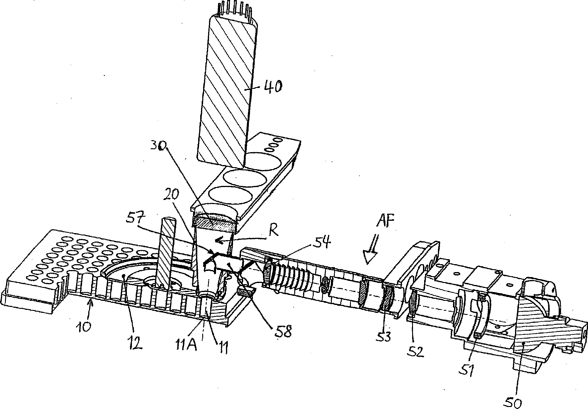
Die
Zwischen
dem ersten Reflektorelement
Zur
Messung von Fluoreszenz beinhaltet ein Anregungslichtpfad AF zunächst
in an sich bekannter Weise eine Lichtquelle
Das
Anregungslicht gelangt in ein Rohr
In
Eine
Fokussierlinse
Die
erfindungscharakteristischen Bauteile dieser Messvorrichtung, die
Reflektorelemente und deren Aufbau und Zuordnung, sind in den
Das
erste Reflektorelement
The first reflector element
Der
Brennpunkt BP1 dieser Parabel und damit der verspiegelten Innenwandung
Das
zur Einführung des Anregungslichtes im Anregungslichtpfad
AF (
Als
zweites Reflektorelement dient ein planer Spiegel
Wie
oben erwähnt, bewirkt die Fokussierlinse
Die
Differenz der Abstände a1 und a2 liegt bei der Verwendung
handelsüblicher Mikrotiterplatten
Mit
den geschilderten mechanischen und optischen Vorkehrungen ergibt
sich ein Emissionslichtpfad EF, dessen Bestandteile in
Ein erster Anteil EF1 (
A first fraction EF1 (
Ein
zweiter Teil EF2 (
Will
man vermeiden, dass der zweite Anteil EF2 des Emissionslichtes den
Detektor erreicht, so kann man oberhalb des Emissionsfilters
Ein
dritter Aneil EF3 (
Ein
Lasermodul
Werden
die optischen Bauteile des Anregungslichtpfads AF durch das Lasermodul
Das
Injektionselement
Anstelle eines Lasermoduls kann wahlweise auch ein weiteres Injektionselement vorgesehen sein.Instead of a laser module can optionally also another injection element be provided.
Ohne
weitere Ausgestaltungen können unter Erzielung der beschriebenen
Vorteile mit der erfindungsgemässen Messvorrichtung folgende
Messverfahren durchgeführt werden:
Das FRET-Verfahren
unterscheidet sich von der Standard-Fluoreszenzmessung dadurch,
dass dieselbe Probe bei zwei unterschiedlichen Emissions-Wellenlängenbereichen
gemessen wird.Without further developments, the following measuring methods can be carried out while achieving the described advantages with the measuring device according to the invention:
The FRET method differs from the standard fluorescence measurement in that the same sample is measured at two different emission wavelength ranges.
Beim TRF-Verfahren wird zur Anregung eine gepulste Lichtquelle, üblicherweise eine Xenon-Blitzlampe, verwendet. Für jede Messung erfolgt eine Serie von Blitzen, nach jedem Blitz wird nach einer anfänglichen Zeitverzögerung in einem bestimmten Zeitfenster die Emissionsstrahlung gemessen. Hierdurch werden Störsignale durch Fluoreszenz mit kürzerer Abklingzeit, als sie die bei TRF verwendeten Markierungen haben, ausgeschaltet.At the TRF method is used to excite a pulsed light source, usually a xenon flash lamp used. For each measurement takes place a series of flashes, after each flash is after an initial flash Time delay in a given time window the emission radiation measured. This causes interference by fluorescence with a shorter cooldown than the markers used in TRF have, turned off.
Das TR-FRET-Verfahren ist eine Kombination aus FRET und TRF derart, dass bei jeder Probe TRF bei zwei verschiedenen Emissions-Wellenlängen gemessen wird.The TR-FRET method is a combination of FRET and TRF such, that at each sample TRF at two different emission wavelengths is measured.
Zur Messung der Absorption befindet sich unter dem transparenten Boden eines Probenbehälters eine Fotodiode. Damit wird in bekannter Weise die Schwächung des durch den Anregungslichtptad kommenden Lichts beim vertikalen Durchtritt durch die Probe gemessen.to Measurement of absorption is below the transparent bottom a sample container a photodiode. This is known in the Way the weakening of the coming through the excitation light path Light measured during vertical passage through the sample.
Weitere
Anwendungen und Ausbildungen der Erfindung werden nun anhand der
Bei
Fluoreszenz-Polarisation wird die Probe von der Lichtquelle mit
polarisiertem Licht bestrahlt (Anregungslichtpfad), im Emissionslichtpfad
werden die Anteile bestimmt, die einerseits parallel, andererseits senkrecht
zur Polarisationsrichtung des eingestrahlten Lichts der Lichtquelle
polarisiert sind.Other applications and embodiments of the invention will now be described with reference to
In fluorescence polarization, the sample is irradiated by the light source with polarized light (excitation light path), in the emission light path the proportions are determined, which are polarized on the one hand parallel, on the other hand perpendicular to the polarization direction of the incident light of the light source.
Dazu
dient die in
Unmittelbar über
der Probe befindet sich eine von zwei Polarisationsfilteranordnungen
PF1, PF2, die nacheinander über die Probe positioniert
und in Bezug auf die optische Achse des Emissionslichtpfades EP
zentriert werden.The purpose of this is in
Immediately above the sample is one of two polarization filter arrays PF1, PF2, which are successively positioned over the sample and centered with respect to the optical axis of the emission light path EP.
Die
Polarisationsfilteranordnungen PF1, PF2 sind beim dargestellten
Ausführungsbeispiel konstruktiv auf demselben Blendenrad
In jeder dieser beiden Polarisationsfilteranordnungen PF1, PF2 befindet sich jeweils in der Mitte ein erstes, kreisförmiges Polarisationsfilter PF11, PF21, umgeben von einem zweiten, ringförmigen Polarisationsfilter PF12, PF22.In each of these two polarization filter arrangements PF1, PF2, a first, circular polarization filter PF11, PF21 is located in each case in the middle, surrounded by a second, annular Po larisation filter PF12, PF22.
Bei
der ersten Filteranordnung PF1 ist die Polarisationsrichtung der
beiden Polarisationsfilter PF11, PF12 im inneren Kreis- und äußeren
Ring-Bereich parallel, bei der zweiten Filteranordnung PF2 ist die
Polarisationsrichtung der beiden Polarisationsfilter PF21, PF22
senkrecht zueinander (die Schraffur in
Bei
der in
Eine
Anpassung der Dimensionierung der oben beschriebenen optischen Bauteile
im Anregungslichtpfad AF an den Durchmesser der ersten Polarisationsfilter
PF11, PF21 ist so vorgenommen, dass die Anregungsstrahlung (Pfeil
nach unten) nur durch den ersten Polarisationsfilter PF11, PF21
in die Probe eintritt, und dass im Emissionslichtpfad EP vom austretenden
Emissionslicht nur derjenige Teil gemessen wird (Pfeile nach oben),
der durch den zweiten Polarisationsfilter PF12, PF22 austritt. Letzteres
wird auch durch die vom vertikalen Abschnitt
Zur Messung einer Probe werden nacheinander die beiden Polarisationsfilteranordnungen PF1, PF2 in die Messposition über die Probe gebracht, das Verhältnis der dabei gemessenen Intensitäten ergibt ein Maß für die Polarisation bzw. Depolarisation.to Measurement of a sample are successively the two polarizing filter arrangements PF1, PF2 placed in the measuring position over the sample, the ratio the measured intensities gives a measure of the polarization or depolarization.
Eine
weitere vorteilhafte Ausgestaltung der erfindungsgemässen
Vorrichtung (
Der
Anregungslichtpfad AP entspricht dem oben für Fluoreszenzmessungen
erläuterten, jedoch trifft hier das Licht nicht direkt
auf die Probe, sondern tritt zunächst in einen Lichtleiter
Der
Lichtleiter
Vom
Austrittsende des Lichtleiterbündels
Bei dieser Anordnung ist die Probe gegenüber der optischen Achse des Emissionslichtpfads EP in der Reflexionskammer R seitlich versetzt.at This arrangement is the sample compared to the optical Axis of the emission light path EP in the reflection chamber R laterally added.
Der
Lichtleiter
Eine weitere Ausgestaltung der Erfindung betrifft den Bereich zwischen der oberen Austrittsöffnung des ersten Reflektorelements, welches z. B. als Rotationsparaboloid realisiert sein kann, und dem Detektor.A Another embodiment of the invention relates to the area between the upper outlet opening of the first reflector element, which z. B. can be realized as a paraboloid of revolution, and the detector.
Es
wurde bereits dargelegt, dass ein als EF2 bezeichneter Teil des
Emissionslichtes (
Bei bestimmten Formen der Fluoreszenzmessung, insbesondere TR-FRET, hat es sich als vorteilhaft erwiesen, oberhalb des Emissionsfilters eine Linse anzu ordnen, welche das Emissionslicht auf den Detektor hin konvergierend leitet und unter Umständen auf den Bereich der Detektoreintrittsfläche fokussiert. Je nach Messaufgabe werden dann noch verschiedene Eintrittsblenden vor den Detektor platziert.at certain forms of fluorescence measurement, in particular TR-FRET, it has proved to be advantageous, above the emission filter a Lens to arrange, which the emission light on the detector out Converges forward and may affect the area the detector entrance surface focused. Depending on the measurement task Then different entrance apertures are placed in front of the detector.
Erfindungsgemäß befinden sich zwischen der oberen Austrittsöffnung des ersten Reflektors und dem Detektor austauschbare Module, die je nach Messaufgabe in den optischen Pfad gebracht werden.According to the invention between the upper outlet opening of the first reflector and the detector interchangeable modules, depending on the measurement task in the be brought optical path.
Eine
bevorzugte Ausführungsform zeigt
Die Schiene mit den daran befestigten Modulen ist ihrerseits an einer (nicht abgebildeten) Linearführung fixiert.The Rail with the attached modules is in turn at one Fixed (not shown) linear guide.
Durch
einen Motor (nicht abgebildet) wird über ein Antriebsrad
Zwischen
der Austrittsöffnung aus der Reflexionskammer und der Eintrittsöffnung
in den U-Bügel befindet sich der Filterschieber
Die Trägerschiene ist so ausgerichtet, dass jedes daran montierte Modul in die erforderliche Position im Emissionslichtpfad gebracht werden kann.The Carrier rail is aligned so that each mounted on it Module placed in the required position in the emission light path can be.
Die Trägerschiene kann mit Hilfe ihres Antriebs die Module nach Öffnen einer lichtdichten Türklappe aus dem Gerät herausfahren, so dass der Benutzer die Modulbestückung ändern oder überprüfen kann. Zur Identifikation der Module können diese mit einem Barcode-Label oder einem Radio-Frequency-Identification (RFID) Modul versehen sein.The Carrier rail can with the help of their drive the modules after opening a light-tight door flap from the Pull out the device so that the user can change the module configuration or can check. For identification of the modules These can be labeled with a barcode label or a Radio Frequency Identification (RFID) module be provided.
Im einfachsten Falle ist das Gerät mit nur einem optischen Modul bestückt. Die Module und der Transportmechanismus sind so konstruiert, dass unterschiedliche Module schnell, d. h. in weniger als 0,5 Sekunden in den Emissionslichtpfad gebracht werden können. Dies erlaubt, dass dieselbe Probe, bzw. dieselbe Mikroplatte mit verschiedenen optischen Verfahren gemessen werden kann.in the The simplest case is the device with only one optical Module equipped. The modules and the transport mechanism are designed so that different modules quickly, d. H. be brought into the emission light path in less than 0.5 seconds can. This allows the same sample, or the same Microplate can be measured by various optical methods can.
Alle Module haben gleiche Außenabmessungen und die äußere Form von Quadern, wozu noch identische Teile zum Befestigen der Module an der Schiene kommen, so dass sie leicht ausgetauscht werden können.All Modules have the same external dimensions and the outer ones Form of blocks, to which still identical parts for securing the Modules come on the rail so they are easily replaced can.
Im Folgenden wird der Aufbau einzelner Module im Detail beschrieben.in the The structure of individual modules will be described in detail below.
Es hat sich gezeigt, dass der optimale Durchmesser der Blende vor dem Detektor je nach Anwendung verschieden ist. Daher werden verschiedene Module mit jeweils unterschiedlichen Blendenformen vorgesehen.It has been shown that the optimal diameter of the aperture before the Detector varies depending on the application. Therefore, different modules provided with different aperture shapes.
Solange der optische Teil der einzelnen Module im wesentlichen unverändert bleibt, können als kostengünstige Alternative die unterschiedlichen optischen Konstruktionen die als Zwischenoptik bezeichnet werden sollen, auch in einem einzigen, also nicht-modularen Schieber oder Rad untergebracht werden. Dieser Schieber läuft oberhalb des Filterschiebers und erlaubt eine beliebige Kombination von optischem Filter und Zwischenoptik.So long the optical part of the individual modules essentially unchanged stays can be considered a cost effective alternative the different optical constructions than the intermediate optics should be designated, even in a single, so non-modular Slider or wheel can be accommodated. This slider is running above the filter slide and allows any combination of optical filter and intermediate optics.
Der erfindungsgemäße Geräteaufbau mit Modulen unterscheidet sich in wesentlichen Aspekten von anderen bekannten Konzepten.Of the Device construction according to the invention with modules differs in essential aspects from other known ones Concepts.
In
Dieser teilt das Licht in zwei Wellenlängenbereiche auf. Jeder der beiden so gebildeten Teilstrahlen verlässt das Modul durch je eine weitere Apertur, um schließlich über zwei Filter und entsprechende Linsen in zwei Detektoren getrennt gemessen zu werden.This divides the light into two wavelength ranges. Everyone of the two sub-beams thus formed leaves the module through each a further aperture to finally over two filters and corresponding lenses separated into two detectors to be measured.
Diese Optik hat zunächst den entscheidenden Nachteil, dass die beiden dichroischen Spiegel bzw. Strahlteiler nur durch entweder konvergente oder divergente Lichtstrahlen getroffen werden, während die beste Performance nur bei parallelem Lichteinfall erreicht wird.These Optics initially has the decisive disadvantage that the both dichroic mirrors or beam splitters only by either convergent or divergent light rays are hit while the best performance is achieved only with parallel incidence of light.
Ein
anderer wesentlicher Nachteil dieser Optik ist, dass sie nicht zur
empfindlichen Messung von Chemilumineszenz geeignet ist. Für
diesen Zweck wird ein optionaler Detektor
Die erfindungsgemäße Anordnung vermeidet diese Nachteile und hat darüber hinaus weitere Vorteile.The arrangement according to the invention avoids these disadvantages and has other benefits as well.
Zunächst ist der Spiegel, der das Anregungslicht zur Probe lenkt, nicht Bestandteil eines Moduls, weil mit der Erfindung eine universell brauchbare Anordnung gefunden wurde, die nicht entsprechend dem gewählten Messprinzip jeweils geändert werden muss. Daher müssen diese Funktionen nicht wieder in jedem Modul enthalten sein, wodurch diese einfacher, kleiner und billiger werden. Wegen der hohen optischen Effizienz der Reflexionskammer kann auch Chemilumineszenz mit derselben Optik und demselben Detektor wie bei der Fluoreszenz gemessen werden, und zwar mit höchster Empfindlichkeit.First, the mirror that directs the excitation light to the sample, not part of a module, because with the invention, a universally useful arrangement was found, which does not have to be changed according to the chosen measuring principle. Therefore, these functions do not have to be included in each module, making them simpler, smaller, and cheaper. Because of the high optical efficiency of the reflection chamber, chemiluminescence can also be measured with the same optics and detector as fluorescence, with the highest sensitivity.
Injektion von Reagenzien in die Messposition ist möglich, außerdem können wellenlängenabhängige Chemilumineszenzmessungen durch Einbringen von Filtern in den optischen Pfad erfolgen.injection of reagents in the measuring position is possible, as well can use wavelength-dependent chemiluminescence measurements by introducing filters into the optical path.
Da die Strahlung nicht durch Aperturen in das Modul eintritt, wird auch die mechanische Justierung unkritischer, was bei austauschbaren Modulen wichtig ist.There the radiation does not enter the module through apertures also the mechanical adjustment uncritical, what with exchangeable Modules is important.
Beim erfindungsgemäßen Aufbau werden auch keine am Modul befindlichen Aperturöffnungen zur Einstellung des Durchmessers des auf die Probe treffenden Lichtstrahles verwendet, da hierzu das direkt über der Probe befindliche Blenden rad 12 dient, welches Blenden mit unterschiedlichen Durchmessern und Formen enthält.At the structure according to the invention are also no am Module located aperture openings for adjusting the Diameter of the light beam striking the sample, since this is the aperture directly above the sample Rad 12 is used which aperture with different diameters and forms.
Um maximale Flexibilität bei der Auswahl der zu messenden Wellenlängen zu erhalten, können Geräte auch mit Monochromatoren ausgerüstet werden. Mit diesen können über weite Spektralbereiche die gewünschten Wellenlängen ausgewählt werden. Zur optimalen Unterdrückung nicht erwünschter Wellenlängen werden Doppelmonochromatoren verwendet, von denen sich einer im Anregungslichtpfad, ein zweiter im Emissionslichtpfad befindet.Around maximum flexibility in the selection of the to be measured Wavelengths can be obtained by devices also be equipped with monochromators. With these can over long spectral ranges the desired Wavelengths are selected. To the optimum Suppression of unwanted wavelengths double monochromators are used, one of which is in the Excitation light path, a second located in the emission light path.
Allerdings haben Monochromatoren gegenüber Filtern auch Nachteile, da sie in einigen Spektralbereichen zu deutlich niedrigeren Nachweisempfindlichkeiten bei Multi-Label-Readern führen. Aus diesem Grunde wird gewünscht, dass in einem einzigen Gerät wahlweise mit Filtern oder mit Monochromatoren gemessen werden kann, wobei die Umschaltung zwischen den beiden Betriebsarten so einfach wie möglich sein soll.Indeed Monochromators also have disadvantages compared to filters. since they lead to significantly lower detection sensitivities in some spectral ranges lead to multi-label readers. That's why desired that in a single device optional can be measured with filters or with monochromators, where Switching between the two modes is as easy as possible should be.
Zur
Messung mit Monochromatoren eignet sich zum Lichttransport in die
Reflexionskammer die in
Auch ist für die Messung der Lichtabsorption mit einem unter dem transparenten Boden einer Mikroplatte positionierten Detektor eine ganz andere Fokusposition erforderlich als bei einer Fluoreszenzmessung.Also is for the measurement of light absorption with an under the transparent bottom of a microplate positioned detector a very different focus position required than in a fluorescence measurement.
Der Brennpunkt kann auch oberhalb der Probe positioniert werden, so dass darunter ein divergentes Lichtbündelt entsteht. Dies kann wünschenswert sein, um die gesamte Bodenfläche eines Probennäpfchens mit Anregungslicht zu bestrahlen.Of the Focus can also be positioned above the sample, so that under it creates a divergent bundle of light. This may be desirable to the entire floor area to irradiate a sample well with excitation light.
Die Einbringung des Anregungslichtes in die Reflexionskammer mit einem Lichtleiter ist zweckmäßig, wenn im Anregungspfad ein Monochromator benutzt wird und der Lichtleiter das Licht direkt vom Ausgang des Monochromators in den Emitterkopf bringt. Der Lichtleiter kann durch entsprechende Anordnung der Fasern gleichzeitig dazu dienen, das rechteckige Profil des Lichts am Austrittsspalt des Monochromators in ein rundes Profil am Ende des Lichtleiters im Emitterkopf zu wandeln.The Introduction of the excitation light in the reflection chamber with a Light guide is appropriate when in the excitation path a monochromator is used and the light guide uses the light directly from the output of the monochromator into the emitter head brings. The light guide can by appropriate arrangement of the fibers at the same time serve, the rectangular profile of the light at the exit slit of the monochromator in a round profile at the end of the light guide in the emitter head too convert.
Wenn das Licht im Emissionspfad wiederum einem Monochromator zugeführt werden soll, so ist die Ausführung der Reflexionskammer als Teil eines innen verspiegelten Rotationsellipsoids zweckmäßig, das die von der Probe emittierte Strahlung auf einen Lichtleiter fokussiert.If the light in the emission path in turn fed to a monochromator should be, so is the execution of the reflection chamber as part of an internally mirrored ellipsoid of revolution, the the radiation emitted by the sample focused on a light guide.
Die
Reflexionskammer kann auch ein Rotationsparaboloid sein, wobei das
aus der oberen Öffnung austretende, im Wesentlichen parallele
Licht mit einer Linse (
Die hier beschriebene Anordnung mit Lichtleiter und Emitterkopf ist nicht auf die Verwendung von Monochromatoren begrenzt. Der Lichtleiter im Anregungspfad kann das Licht auch nach Durchgang durch Filter und entsprechende Fokussierung auf seinen Eingangsquerschnitt, der in diesem Falle rund sein könnte, in die Reflexionskammer bringen.The here described arrangement with optical fiber and emitter head not limited to the use of monochromators. The light guide in the excitation path, the light can also after passing through filters and corresponding focus on its input cross section, the in this case could be round, in the reflection chamber bring.
In
einer weiteren Ausgestaltung der Erfindung wird das Anregungslicht
bis unmittelbar über die Probe nach außen vollständig
abgeschirmt geführt. Dafür sind mehrere Realisierungen
möglich:
Die
The
Wird
das Anregungslicht durch einen Lichtleiter zur Probe gebracht, so
kann, wie in
In
beiden Versionen stellt die über der Probe gelegene Lichtaustrittsöffnung
gleichzeitig eine Blende dar, bei welcher sichergestellt ist, dass
die innen auflaufende Streustrahlung nicht in den Emissionsstrahlengang
gelangen und eine Erhöhung der Hintergrundstrahlung verursachen
kann. Die innere und äußere Oberfläche
des Rohres
Der
Bereich der Abschirmung zwischen der sich über der Probe
befindlichen Linse und der Probe kann modular gestaltet sein, wobei
diverse auf einem Schieber oder einer Scheibe
Bei einer Reihe von Messverfahren, wie z. B. BRET, FRET oder TR-FRET ist es erforderlich, dass aus derselben Probe die Intensität des emittierten Lichtes in zwei unterschiedlichen Wellenlängenbereichen gemessen wird. Üblicherweise werden dazu nacheinander zwei Messungen mit unterschiedlichen optischen Fil tern vogenommen.at a number of measuring methods, such. BRET, FRET or TR-FRET it is necessary that from the same sample the intensity of the emitted light in two different wavelength ranges is measured. Usually, two will be used successively Measurements with different optical filters accepted.
Die
Dabei
bilden sich zusätzlich zur vertikal durch die Probe verlaufenden
optischen Hauptachse
Die zwischen der oberen Austrittsöffnung jedes Paraboloids und dem jeweiligen Detektor befindlichen Filter sind auf einem Filterschieber oder Filterrad montiert, sodass unterschiedliche Filter oder auch Leerpositionen jederzeit gegeneinander ausgetauscht werden können.The between the upper outlet of each paraboloid and the filter located at the respective detector are on a filter slide or filter wheel mounted so different filters or else Empty positions can be exchanged against each other at any time.
Der
Anregungslichtpfad beginnt am oberen Teil der optischen Hauptachse
Das
Anregungslicht kann auch von einem Monochromator im Anregungspfad
kommen, in diesem Falle ist die in
Die Detektoren können entweder direkt hinter den Emissionsfiltern stehen oder es werden noch weitere optische Komponenten wie z. B. Reflektoren, Linsen oder Blenden zwischen Filter und Detektoren positioniert.The Detectors can either be directly behind the emission filters stand or there are other optical components such. B. Reflectors, lenses or diaphragms positioned between filters and detectors.
Für Standard-Lumineszenzmessungen, bei denen keine Filter benötigt werden, können die Signale beider Detektoren addiert werden, um maximale Empfindlichkeit zu erreichen. Wenn die beiden Detektoren schnelle Photon-Counter sind, können sie auch mit einer Koinzinzidenzschaltung betrieben werden, um als Szintillationszähler Radioaktivitätsmessungen mit höchster Empfindlichkeit zu erlauben.For Standard luminescence measurements that do not require filters can be added, the signals of both detectors, to achieve maximum sensitivity. If the two detectors fast photon counters are, you can also use one Coincidence circuit operated to act as a scintillation counter Radioactivity measurements with highest sensitivity to allow.
- AFAF
- AnregungslichtpfadExcitation light path
- EFEF
- EmissionslichtpfadEmission light path
- RR
- Reflexionskammerreflection chamber
- 1010
- Mikrotiterplattemicrotiter plate
- 1111
- Probenbehältersample container
- 1212
- Blendenradaperture wheel
- 20, 2120 21
- erstes Reflektorelementfirst reflector element
- 20A, 21A20A, 21A
- Innenwandunginner wall
- BP1, BP2, BP3BP1, BP2, BP3
- Brennpunktefoci
- 3030
- Emissionsfilteremission filter
- 3131
- Hohlzylinderhollow cylinder
- 4040
- Detektordetector
- 5050
- Lichtquellelight source
- 5151
- Blendecover
- 5252
- Linselens
- 5353
- Anregungsfilterexcitation filter
- 5454
- Fokussierlinsefocusing lens
- a1a1
- erster Abstandfirst distance
- a2a2
- zweiter Abstandsecond distance
- 5555
- Spiegelmirror
- 5656
- Referenzdetektorreference detector
- 5757
- Umlenkspiegeldeflecting
- 5858
- Rohrpipe
- 58A58A
- horizontaler Abschnitthorizontal section
- 58B58B
- vertikaler Abschnittvertical section
- 5959
- Halterungbracket
- 6060
- Lasermodullaser module
- 6161
- Injektionselementinjection site
- 6262
- Lichtleiteroptical fiber
- 62A62A
- inneres Lichtleiterbündelinner Light pipe
- 62B62B
- äusseres Lichtleiterbündelouter Light pipe
- 6363
- U-BügelU-bolts
- 63a63a
- erste Öffnungfirst opening
- 7070
- Detektordetector
- 71,7271.72
- Modulmodule
- 7373
- Trägerschienesupport rail
- 7474
- Schraubescrew
- 7575
- Antriebsraddrive wheel
- 7676
- Zahnriementoothed belt
- 7777
- Filterschieberfilter slider
- 110110
- Lichtleiteroptical fiber
- 111111
- Emitterkopfemitter head
- 112112
- Ende des LichtleitersThe End of the light guide
- 113113
- Verbindungsstückjoint
- 114114
- Haltevorrichtungholder
- 116116
- Linselens
- 118118
- Rohrpipe
- 119119
- Abschirmrohrshielding
- 121, 122121 122
- Teilbereich der Reflexionskammersubregion the reflection chamber
- 123, 124123 124
- Öffnungopening
- 125, 126125 126
- Filterfilter
- 127, 128127 128
- Detektordetector
- 129129
- Hauptachsemain axis
- 130, 131130 131
- Nebenachseminor axis
- 150150
- Scheibedisc
- 150a, 150b150a, 150b
- Austrittsöffnungoutlet opening
ZITATE ENTHALTEN IN DER BESCHREIBUNGQUOTES INCLUDE IN THE DESCRIPTION
Diese Liste der vom Anmelder aufgeführten Dokumente wurde automatisiert erzeugt und ist ausschließlich zur besseren Information des Lesers aufgenommen. Die Liste ist nicht Bestandteil der deutschen Patent- bzw. Gebrauchsmusteranmeldung. Das DPMA übernimmt keinerlei Haftung für etwaige Fehler oder Auslassungen.This list The documents listed by the applicant have been automated generated and is solely for better information recorded by the reader. The list is not part of the German Patent or utility model application. The DPMA takes over no liability for any errors or omissions.
Zitierte PatentliteraturCited patent literature
- - EP 0803724 A2 [0011] EP 0803724 A2 [0011]
- - EP 1279946 A1 [0012, 0034] - EP 1279946 A1 [0012, 0034]
- - US 6891681 B2 [0017, 0118] US 6891681 B2 [0017, 0118]
- - EP 1279964 A1 [0063] - EP 1279964 A1 [0063]
Claims (50)
Priority Applications (3)
| Application Number | Priority Date | Filing Date | Title |
|---|---|---|---|
| DE202008009859U DE202008009859U1 (en) | 2007-12-21 | 2008-07-23 | Device for the optional measurement of in particular luminescence and / or fluorescence radiation |
| EP08021417.4A EP2072998B1 (en) | 2007-12-21 | 2008-12-10 | Device for the optional measurement of in particular luminescence and/or fluorescence radiation |
| US12/341,573 US20090159803A1 (en) | 2007-12-21 | 2008-12-22 | Apparatus for selected measurement of, in particular luminescent and/or fluorescent radiation |
Applications Claiming Priority (3)
| Application Number | Priority Date | Filing Date | Title |
|---|---|---|---|
| DE202007017895.6 | 2007-12-21 | ||
| DE202007017895 | 2007-12-21 | ||
| DE202008009859U DE202008009859U1 (en) | 2007-12-21 | 2008-07-23 | Device for the optional measurement of in particular luminescence and / or fluorescence radiation |
Publications (1)
| Publication Number | Publication Date |
|---|---|
| DE202008009859U1 true DE202008009859U1 (en) | 2009-03-05 |
Family
ID=40418508
Family Applications (1)
| Application Number | Title | Priority Date | Filing Date |
|---|---|---|---|
| DE202008009859U Expired - Lifetime DE202008009859U1 (en) | 2007-12-21 | 2008-07-23 | Device for the optional measurement of in particular luminescence and / or fluorescence radiation |
Country Status (3)
| Country | Link |
|---|---|
| US (1) | US20090159803A1 (en) |
| EP (1) | EP2072998B1 (en) |
| DE (1) | DE202008009859U1 (en) |
Cited By (5)
| Publication number | Priority date | Publication date | Assignee | Title |
|---|---|---|---|---|
| DE202011001569U1 (en) | 2011-01-14 | 2012-03-01 | Berthold Technologies Gmbh & Co. Kg | Device for measuring optical properties in microplates |
| DE102011055070B3 (en) * | 2011-11-04 | 2013-03-07 | Seramun Diagnostica Gmbh | A sample analysis apparatus for determining samples in a sample matrix and methods for determining samples in one or more sample matrices |
| DE102013100658A1 (en) | 2013-01-23 | 2014-07-24 | Seramun Diagnostica Gmbh | Optical assaying of test array arrangement in sample volume by sample analysis device, comprises e.g. providing sample matrix, optically detecting measuring array arrangement, digital processing of image recording, and mapping results |
| DE102015214414A1 (en) * | 2015-07-29 | 2017-02-02 | Berthold Technologies Gmbh & Co. Kg | Method and system for determining biological properties of samples |
| EP3614130A1 (en) * | 2018-08-22 | 2020-02-26 | Berthold Technologies GmbH & Co. KG | Device for determining optical properties of samples |
Families Citing this family (16)
| Publication number | Priority date | Publication date | Assignee | Title |
|---|---|---|---|---|
| JP5524698B2 (en) * | 2010-04-27 | 2014-06-18 | 株式会社日立ハイテクノロジーズ | Automatic analyzer |
| KR101917402B1 (en) * | 2011-02-04 | 2019-01-24 | 유니바사루 바이오 리사치 가부시키가이샤 | Automatic response/light measurement device and method therefor |
| JP6256345B2 (en) * | 2012-10-26 | 2018-01-10 | ソニー株式会社 | Condensing unit, condensing method, and light detection system |
| US20150177236A1 (en) * | 2013-03-15 | 2015-06-25 | Gold Standard Diagnostics | Combined chemiluminescence and elisa automated sample reader |
| JP2017527822A (en) | 2014-06-27 | 2017-09-21 | パルス ヘルス エルエルシー | Fluorescence detection assembly |
| US9261459B1 (en) * | 2014-08-12 | 2016-02-16 | Ecolab Usa Inc. | Handheld fluorometer |
| CN107850546B (en) * | 2015-07-30 | 2020-05-12 | 株式会社日立高新技术 | Detection device for luminescence analysis and automatic analysis device |
| JP6249089B2 (en) * | 2016-12-27 | 2017-12-20 | 株式会社島津製作所 | Detector for liquid chromatography |
| US10473591B2 (en) * | 2017-05-01 | 2019-11-12 | Wyatt Technology Corporation | High throughput method and apparatus for measuring multiple optical properties of a liquid sample |
| DE102018200646A1 (en) | 2018-01-16 | 2019-07-18 | Berthold Technologies Gmbh & Co. Kg | System for measuring optical properties of samples |
| DE102018218047A1 (en) * | 2018-10-22 | 2020-04-23 | Robert Bosch Gmbh | Shielding device for a chip laboratory analyzer, chip laboratory analyzer and method for operating a chip laboratory analyzer |
| CN110174352A (en) * | 2019-04-12 | 2019-08-27 | 吉林亚泰中科医疗器械工程技术研究院股份有限公司 | A kind of homogeneous phase time discrimination light path detecting device on multi-function microplate reader |
| DE102019215112A1 (en) * | 2019-10-01 | 2021-04-01 | Robert Bosch Gmbh | Device for shielding a light path and chip laboratory analyzer |
| EP3869183A1 (en) | 2020-02-24 | 2021-08-25 | Berthold Technologies GmbH & Co. KG | Device for determining the optical properties of samples |
| CN115931808A (en) * | 2023-02-09 | 2023-04-07 | 北京鹏宇昌亚环保科技有限公司 | Totally-enclosed light path device of mercury detector |
| CN117406362B (en) * | 2023-12-14 | 2024-03-05 | 鲲鹏基因(北京)科技有限责任公司 | Clamp spring connection structure, optical detection device for PCR instrument and PCR instrument |
Citations (4)
| Publication number | Priority date | Publication date | Assignee | Title |
|---|---|---|---|---|
| EP0803724A2 (en) | 1996-04-22 | 1997-10-29 | Wallac Oy | Device using several optical measuring methods |
| EP1279946A2 (en) | 2001-07-28 | 2003-01-29 | Berthold Technologies GmbH & Co. KG | Apparatus for alternative measurement of luminescence and/or fluorescence radiation |
| EP1279964A1 (en) | 2001-07-17 | 2003-01-29 | Texas Instruments Deutschland Gmbh | Resistance measuring circuit |
| US6891681B2 (en) | 2000-04-22 | 2005-05-10 | Optrel Ag | Anti-glare protection device |
Family Cites Families (35)
| Publication number | Priority date | Publication date | Assignee | Title |
|---|---|---|---|---|
| EP0148497B1 (en) * | 1983-12-24 | 1990-10-31 | Inotech Ag | Device for guiding and collecting light in photometry or the like |
| US4567370A (en) * | 1984-02-21 | 1986-01-28 | Baird Corporation | Authentication device |
| US5318024A (en) * | 1985-03-22 | 1994-06-07 | Massachusetts Institute Of Technology | Laser endoscope for spectroscopic imaging |
| US5089424A (en) * | 1988-06-14 | 1992-02-18 | Abbott Laboratories | Method and apparatus for heterogeneous chemiluminescence assay |
| EP0539743B1 (en) * | 1991-09-30 | 1997-08-06 | Beckman Instruments, Inc. | Enhanced fluorescence detection of samples in capillary column |
| US5614726A (en) * | 1995-03-23 | 1997-03-25 | Beckman Instruments, Inc. | Automated optical alignment system and method using Raman scattering of capillary tube contents |
| FI954511A0 (en) * | 1995-09-22 | 1995-09-22 | Labsystems Oy | fluorometer |
| US5611994A (en) * | 1995-11-22 | 1997-03-18 | Dynatech Laboratories, Inc. | Luminometer |
| JPH1019779A (en) * | 1996-06-28 | 1998-01-23 | Shimadzu Corp | Weak fluorescence measuring apparatus |
| CA2279574C (en) * | 1997-01-31 | 2007-07-24 | The Horticulture & Food Research Institute Of New Zealand Ltd. | Optical apparatus |
| DE19704732A1 (en) * | 1997-02-07 | 1998-08-13 | Stratec Elektronik Gmbh | Luminescence measurement device |
| EP0864898A1 (en) * | 1997-03-12 | 1998-09-16 | Karrai-Haines GbR | Near-field optical microscope |
| EP0864846A3 (en) * | 1997-03-12 | 2000-12-13 | Haines, Miles, Dr. | Scanning probe microscope |
| US6124597A (en) * | 1997-07-07 | 2000-09-26 | Cedars-Sinai Medical Center | Method and devices for laser induced fluorescence attenuation spectroscopy |
| US6097025A (en) * | 1997-10-31 | 2000-08-01 | Ljl Biosystems, Inc. | Light detection device having an optical-path switching mechanism |
| US5900942A (en) * | 1997-09-26 | 1999-05-04 | The United States Of America As Represented By Administrator Of National Aeronautics And Space Administration | Multi spectral imaging system |
| DE19810615A1 (en) * | 1998-03-12 | 1999-09-16 | Thomas Ruckstuhl | High efficiency optical system detecting light from e.g. excited marked biomolecules |
| AU4999099A (en) * | 1998-07-15 | 2000-02-07 | Ljl Biosystems, Inc. | Evanescent field illumination devices and methods |
| US6232608B1 (en) * | 1998-08-18 | 2001-05-15 | Molecular Devices Corporation | Optimization systems in a scanning fluorometer |
| DE19841931C2 (en) * | 1998-09-14 | 2002-06-20 | Zeiss Carl Jena Gmbh | Microscope for optical near-field microscopy |
| CA2371782A1 (en) * | 1999-01-25 | 2000-07-27 | Newton Laboratories, Inc. | Imaging of tissue using polarized light |
| US6795189B2 (en) * | 2000-06-15 | 2004-09-21 | Packard Instrument Company | Universal microplate analyzer |
| US7352459B2 (en) * | 2000-12-29 | 2008-04-01 | Chromagen, Inc. | Scanning Spectrophotometer for high throughput fluorescence detection and fluorescence polarization |
| JP2002236223A (en) * | 2001-02-09 | 2002-08-23 | Olympus Optical Co Ltd | Fiber probe photodetector |
| AT410375B (en) * | 2001-05-23 | 2003-04-25 | Anthos Labtec Instr Gmbh | fluorometer |
| AT410033B (en) * | 2001-06-06 | 2003-01-27 | Eurolab Instr Gmbh | METHOD AND MEASURING DEVICE FOR DETERMINING AT LEAST ONE LUMINESCENCE, FLOURENCE OR ABSORPTION PARAMETER OF A SAMPLE |
| US20030114919A1 (en) * | 2001-12-10 | 2003-06-19 | Mcquiston Jesse | Polymeric stent with metallic rings |
| US7404929B2 (en) * | 2002-01-18 | 2008-07-29 | Newton Laboratories, Inc. | Spectroscopic diagnostic methods and system based on scattering of polarized light |
| CA2490201A1 (en) * | 2002-06-24 | 2003-12-31 | Tsi Incorporated | Analysis systems detecting particle size and fluorescence |
| US20040057870A1 (en) * | 2002-09-20 | 2004-03-25 | Christer Isaksson | Instrumentation for optical measurement of samples |
| JP4717375B2 (en) * | 2004-05-21 | 2011-07-06 | オリンパス株式会社 | Fluorescence microscope and observation method |
| US20060060189A1 (en) * | 2004-08-30 | 2006-03-23 | Liu Yong Y | Optical reflector and optical collection system |
| US7324202B2 (en) * | 2004-12-07 | 2008-01-29 | Novx Systems Inc. | Optical system |
| US20070008528A1 (en) * | 2005-07-07 | 2007-01-11 | Chi-Hung Lin | Device and method for simultaneous optical trapping, stretching, and real-time detection and measurement for morphological deformation of micro-particles |
| WO2007041458A2 (en) | 2005-10-03 | 2007-04-12 | The Salk Institute For Biological Studies | Maximal-aperture reflecting objective |
-
2008
- 2008-07-23 DE DE202008009859U patent/DE202008009859U1/en not_active Expired - Lifetime
- 2008-12-10 EP EP08021417.4A patent/EP2072998B1/en active Active
- 2008-12-22 US US12/341,573 patent/US20090159803A1/en not_active Abandoned
Patent Citations (4)
| Publication number | Priority date | Publication date | Assignee | Title |
|---|---|---|---|---|
| EP0803724A2 (en) | 1996-04-22 | 1997-10-29 | Wallac Oy | Device using several optical measuring methods |
| US6891681B2 (en) | 2000-04-22 | 2005-05-10 | Optrel Ag | Anti-glare protection device |
| EP1279964A1 (en) | 2001-07-17 | 2003-01-29 | Texas Instruments Deutschland Gmbh | Resistance measuring circuit |
| EP1279946A2 (en) | 2001-07-28 | 2003-01-29 | Berthold Technologies GmbH & Co. KG | Apparatus for alternative measurement of luminescence and/or fluorescence radiation |
Cited By (8)
| Publication number | Priority date | Publication date | Assignee | Title |
|---|---|---|---|---|
| DE202011001569U1 (en) | 2011-01-14 | 2012-03-01 | Berthold Technologies Gmbh & Co. Kg | Device for measuring optical properties in microplates |
| WO2012095312A1 (en) | 2011-01-14 | 2012-07-19 | Berthold Technologies Gmbh & Co. Kg | Device for measuring optical properties of samples in microplates |
| DE102011055070B3 (en) * | 2011-11-04 | 2013-03-07 | Seramun Diagnostica Gmbh | A sample analysis apparatus for determining samples in a sample matrix and methods for determining samples in one or more sample matrices |
| EP2589950A1 (en) | 2011-11-04 | 2013-05-08 | Seramun Diagnostica GmbH | Sample analysis device for determining samples in a sample matrix and method for determining of samples in one or more sample matrices |
| DE102013100658A1 (en) | 2013-01-23 | 2014-07-24 | Seramun Diagnostica Gmbh | Optical assaying of test array arrangement in sample volume by sample analysis device, comprises e.g. providing sample matrix, optically detecting measuring array arrangement, digital processing of image recording, and mapping results |
| DE102015214414A1 (en) * | 2015-07-29 | 2017-02-02 | Berthold Technologies Gmbh & Co. Kg | Method and system for determining biological properties of samples |
| DE102015214414B4 (en) * | 2015-07-29 | 2020-10-22 | Berthold Technologies Gmbh & Co. Kg | Method and system for determining biological properties of samples |
| EP3614130A1 (en) * | 2018-08-22 | 2020-02-26 | Berthold Technologies GmbH & Co. KG | Device for determining optical properties of samples |
Also Published As
| Publication number | Publication date |
|---|---|
| EP2072998B1 (en) | 2013-11-13 |
| US20090159803A1 (en) | 2009-06-25 |
| EP2072998A2 (en) | 2009-06-24 |
| EP2072998A3 (en) | 2009-08-19 |
Similar Documents
| Publication | Publication Date | Title |
|---|---|---|
| EP2072998B1 (en) | Device for the optional measurement of in particular luminescence and/or fluorescence radiation | |
| DE69738555T2 (en) | Device using various optical measuring methods | |
| DE69634963T2 (en) | fluorometer | |
| DE19653413A1 (en) | Scanning microscope, in which a sample is simultaneously optically excited in several sample points | |
| EP0148497A2 (en) | Device for guiding and collecting light in photometry or the like | |
| EP0788615A1 (en) | Method and device for determining substance-specific parameters of one or a plurality of molecules by correlation-spectroscopy | |
| EP1279946B1 (en) | Apparatus for alternative measurement of luminescence and/or fluorescence radiation | |
| DE19745373A1 (en) | Optical measuring system for the detection of luminescence or fluorescence signals | |
| DE10223438B4 (en) | Fluorescence-measuring system | |
| DE19810615A1 (en) | High efficiency optical system detecting light from e.g. excited marked biomolecules | |
| DE4331570C2 (en) | Process for the optical excitation of a sample | |
| DE102004016361B4 (en) | Optical analyzer for fluorescence measurements on multiprobe carriers | |
| DE60205406T2 (en) | OPTICAL TWO-WAVELENGTH FLUORESCENT ANALYZER | |
| EP3271694A1 (en) | Light emission measuring device and method for measuring light emission | |
| DE10297062B4 (en) | Atomic Absorption Spectrometer | |
| EP3869183A1 (en) | Device for determining the optical properties of samples | |
| EP2663854A1 (en) | Device for measuring optical properties of samples in microplates | |
| WO2007135091A2 (en) | Module for reading from a biochip | |
| DE10221823A1 (en) | Measuring liquid level, degree of fouling of water, other transparent liquids involves passing different emission spectra through liquid, acquiring modified spectra, feeding to optoelectronic receiver | |
| DE10017824B4 (en) | Device for parallel photometric fluorescence or luminescence analysis of several separate sample areas on an object | |
| WO1999047914A1 (en) | Thin-layer chromatography apparatus | |
| DE19543729B4 (en) | spectrometer | |
| DE10155142A1 (en) | Dark-field imaging device for spatially resolved dark-field imaging of a flat sample | |
| EP3273224B1 (en) | Device for determining the optical properties of samples in different operating modes | |
| DE3447437A1 (en) | Method and device for guiding and collecting light in photometry or simular |
Legal Events
| Date | Code | Title | Description |
|---|---|---|---|
| R207 | Utility model specification |
Effective date: 20090409 |
|
| R150 | Utility model maintained after payment of first maintenance fee after three years |
Effective date: 20110419 |
|
| R151 | Utility model maintained after payment of second maintenance fee after six years | ||
| R151 | Utility model maintained after payment of second maintenance fee after six years |
Effective date: 20140505 |
|
| R152 | Utility model maintained after payment of third maintenance fee after eight years | ||
| R082 | Change of representative |
Representative=s name: SCHOEN, THILO, DIPL.-PHYS., DE |
|
| R071 | Expiry of right |