DE202005022038U1 - Free space pointing devices with slope compensation and improved usability - Google Patents
Free space pointing devices with slope compensation and improved usability Download PDFInfo
- Publication number
- DE202005022038U1 DE202005022038U1 DE202005022038U DE202005022038U DE202005022038U1 DE 202005022038 U1 DE202005022038 U1 DE 202005022038U1 DE 202005022038 U DE202005022038 U DE 202005022038U DE 202005022038 U DE202005022038 U DE 202005022038U DE 202005022038 U1 DE202005022038 U1 DE 202005022038U1
- Authority
- DE
- Germany
- Prior art keywords
- pointing device
- rotation
- free space
- value output
- space pointing
- Prior art date
- Legal status (The legal status is an assumption and is not a legal conclusion. Google has not performed a legal analysis and makes no representation as to the accuracy of the status listed.)
- Expired - Lifetime
Links
Images


Classifications
-
- G—PHYSICS
- G06—COMPUTING; CALCULATING OR COUNTING
- G06F—ELECTRIC DIGITAL DATA PROCESSING
- G06F3/00—Input arrangements for transferring data to be processed into a form capable of being handled by the computer; Output arrangements for transferring data from processing unit to output unit, e.g. interface arrangements
- G06F3/01—Input arrangements or combined input and output arrangements for interaction between user and computer
- G06F3/017—Gesture based interaction, e.g. based on a set of recognized hand gestures
-
- G—PHYSICS
- G06—COMPUTING; CALCULATING OR COUNTING
- G06F—ELECTRIC DIGITAL DATA PROCESSING
- G06F3/00—Input arrangements for transferring data to be processed into a form capable of being handled by the computer; Output arrangements for transferring data from processing unit to output unit, e.g. interface arrangements
- G06F3/01—Input arrangements or combined input and output arrangements for interaction between user and computer
- G06F3/03—Arrangements for converting the position or the displacement of a member into a coded form
- G06F3/033—Pointing devices displaced or positioned by the user, e.g. mice, trackballs, pens or joysticks; Accessories therefor
- G06F3/0346—Pointing devices displaced or positioned by the user, e.g. mice, trackballs, pens or joysticks; Accessories therefor with detection of the device orientation or free movement in a 3D space, e.g. 3D mice, 6-DOF [six degrees of freedom] pointers using gyroscopes, accelerometers or tilt-sensors
-
- G—PHYSICS
- G06—COMPUTING; CALCULATING OR COUNTING
- G06F—ELECTRIC DIGITAL DATA PROCESSING
- G06F3/00—Input arrangements for transferring data to be processed into a form capable of being handled by the computer; Output arrangements for transferring data from processing unit to output unit, e.g. interface arrangements
- G06F3/01—Input arrangements or combined input and output arrangements for interaction between user and computer
- G06F3/03—Arrangements for converting the position or the displacement of a member into a coded form
- G06F3/033—Pointing devices displaced or positioned by the user, e.g. mice, trackballs, pens or joysticks; Accessories therefor
- G06F3/038—Control and interface arrangements therefor, e.g. drivers or device-embedded control circuitry
- G06F3/0383—Signal control means within the pointing device
-
- H—ELECTRICITY
- H04—ELECTRIC COMMUNICATION TECHNIQUE
- H04N—PICTORIAL COMMUNICATION, e.g. TELEVISION
- H04N21/00—Selective content distribution, e.g. interactive television or video on demand [VOD]
- H04N21/40—Client devices specifically adapted for the reception of or interaction with content, e.g. set-top-box [STB]; Operations thereof
- H04N21/41—Structure of client; Structure of client peripherals
- H04N21/422—Input-only peripherals, i.e. input devices connected to specially adapted client devices, e.g. global positioning system [GPS]
- H04N21/42204—User interfaces specially adapted for controlling a client device through a remote control device; Remote control devices therefor
- H04N21/42206—User interfaces specially adapted for controlling a client device through a remote control device; Remote control devices therefor characterized by hardware details
- H04N21/42222—Additional components integrated in the remote control device, e.g. timer, speaker, sensors for detecting position, direction or movement of the remote control, microphone or battery charging device
Abstract
Description
VERWANDTE ANMELDUNGENRELATED APPLICATIONS
Diese Anmeldung betrifft die und beansprucht die Priorität der US-Provisional Patentanmeldung mit Seriennummer 60/566,444, eingereicht am 30. April 2004, mit dem Titel ”Freespace Pointing Device”, deren Offenbarung hier durch Inbezugnahme aufgenommen wird. Diese Anmeldung betrifft auch die und beansprucht die Priorität der US-Provisional Patentanmeldung mit Seriennummer 60/612,571, eingereicht am 23. September 2004, mit dem Titel ”Free Space Pointing Devices and Methods”, deren Offenbarung hier durch Inbezugnahme aufgenommen wird. Diese Anmeldung betrifft auch die und beansprucht die Priorität der US-Provisional Patentanmeldung mit Seriennummer 60/641,410, eingereicht am 5. Januar 2005, mit dem Titel ”Free Space Pointing Devices and Methods for Using Same”, deren Offenbarung hier durch Inbezugnahme aufgenommen wird.This application is related to and claims the benefit of US Provisional Patent Application Serial No. 60 / 566,444, filed April 30, 2004, entitled "Freespace Pointing Device," the disclosure of which is incorporated herein by reference. This application also relates to and claims priority to US Provisional Patent Application Serial No. 60 / 612,571, filed September 23, 2004, entitled "Free Space Pointing Devices and Methods," the disclosure of which is incorporated herein by reference. This application also relates to and claims priority to US Provisional Patent Application Serial No. 60 / 641,410, filed January 5, 2005, entitled "Free Space Pointing Devices and Methods for Using Same," the disclosure of which is incorporated herein by reference.
Diese Anmeldung betrifft auch die US-Patentanmeldungen Nr. 11/119,987, 11/119,688 und 11/119,663, mit den Titeln ”Methods and Devices for Removing Unintentional Movement in Free Space Pointing Devices, ”Methods and Devices for Identifying Users Based on Tremor” und ”Free Space Pointing Devices and Methods”, welche sämtlich gleichzeitig mit der vorliegenden Anmeldung eingereicht wurden und welche durch Inbezugnahme hier aufgenommen werden.This application also relates to US Patent Application Nos. 11 / 119,987, 11 / 119,688 and 11 / 119,663, entitled "Methods and Devices for Removing Unintentional Movement in Free Space Pointing Devices," Methods and Devices for Identifying Users Based on Tremor " and "Free Space Pointing Devices and Methods", all of which were filed concurrently with the present application and which are incorporated herein by reference.
HINTERGRUNDBACKGROUND
Die vorliegende Erfindung betrifft im Allgemeinen handgeführte Zeigevorrichtungen und insbesondere Freiraum-Zeigevorrichtungen und Verfahren für die Neigungskompensation und eine damit verbundene verbesserte Benutzbarkeit.The present invention relates generally to hand-held pointing devices, and more particularly to free-space pointing devices and methods for pitch compensation and associated improved usability.
Technologien, die der Informationsübertragung zugeordnet sind, haben sich in den letzten Jahrzehnten rasch entwickelt. Fernsehen, Mobilfunk, Internet und optische Kommunikationsverfahren (um nur ein paar Dinge zu nennen) werden kombiniert, um Verbraucher mit verfügbaren Informationen und Entertainment-Auswahlmöglichkeiten zu überschwemmen. Wird das Fernsehen als ein Beispiel genommen, so haben wir in den letzten drei Jahrzehnten die Einführung des Kabelfernsehens, des Satellitenfernsehens, der Pay-per-View-Filme und des Video-on-Demand erlebt. Während die Fernsehzuschauer in den 60-iger Jahren auf ihren Fernsehgeräten über den Äther normalerweise vielleicht vier oder fünf Fernsehkanäle empfangen konnten, haben die Fernsehzuschauer heutzutage die Möglichkeit, aus hunderten, tausenden und potenziell Millionen von Kanälen von Shows und Informationen auszuwählen. Die Video-on-Demand-Technologie, die gegenwärtig in erster Linie in Hotels und dergleichen eingesetzt wird, stellt das Potenzial für die Auswahl aus tausenden von Filmtiteln zur häuslichen Unterhaltung bereit.Technologies associated with information transfer have developed rapidly in recent decades. Television, mobile, Internet and optical communications (to name but a few) are combined to flood consumers with available information and entertainment choices. If television is taken as an example, we've seen the advent of cable television, satellite television, pay-per-view movies and video-on-demand over the past three decades. While televiewers typically received perhaps four or five television channels on their television sets in the 1960s, television viewers now have the ability to select from hundreds, thousands and potentially millions of channels of shows and information. Video-on-demand technology, which is currently used primarily in hotels and the like, provides the potential to select from thousands of home entertainment titles.
Das technologische Leistungsvermögen, um Endnutzern derartig viele Informationen und Inhalte bereitzustellen, bietet den Systemgestaltern und Dienstanbietern sowohl Chancen als auch Herausforderungen. Eine Herausforderung besteht darin, dass die Endnutzer gewöhnlich zwar vorziehen, über mehr Auswahl zu verfügen als über weniger, dieser Bevorzugung aber ihr Wunsch entgegensteht, dass der Auswahlvorgang sowohl schnell als auch einfach sein sollte. Leider hat die Entwicklung von Systemen und Schnittstellen, durch welche die Endnutzer auf Medienelemente zugreifen, zu Auswahlvorgängen geführt, die weder schnell noch einfach sind. Es soll wieder das Beispiel der Fernsehprogramme betrachtet werden. Als das Fernsehen in seinen Kinderschuhen steckte, war es wegen der geringen Zahl von Auswahlmöglichkeiten ein ziemlich einfacher Vorgang zu entscheiden, welches Programm angeschaut werden sollte. Es konnte ein gedruckter Programmführer zu Rate gezogen werden, der zum Beispiel in einer Reihe von Spalten und Zeilen formatiert war, welche die Übereinstimmung zwischen (1) den in der Nähe gelegenen Fernsehkanälen, (2) den auf diesen Kanälen übertragenen Programmen und (3) dem Datum und der Zeit angezeigt haben. Das Fernsehgerät wurde auf den gewünschten Kanal abgestimmt, indem ein Abstimmknopf eingestellt wurde, und der Zuschauer hat das ausgewählte Programm angeschaut. Später sind die Fernbedienungen eingeführt worden, die es den Zuschauern ermöglicht haben, das Fernsehgerät aus einem Abstand einzustellen. Mit diesem Zusatz zur Nutzer-Fernseher-Schnittstelle wurde das Phänomen des ”Kanalsurfens” geschaffen, wodurch ein Zuschauer schnell kurze Abschnitte anschauen konnte, die auf einer Anzahl von Kanälen gesendet wurden, um in kurzer Zeit zu erfahren, welche Programme zu einer gegebenen Zeit verfügbar waren.The technological ability to provide end users with so much information and content offers both system designers and service providers both opportunities and challenges. One challenge is that while end users usually prefer to have more choice than less, this preference is opposed to their desire that the selection process should be both quick and easy. Unfortunately, developing systems and interfaces that allow end users to access media assets has led to selections that are neither quick nor easy. Let's look again at the example of television programs. When television was in its infancy, it was a pretty straightforward process to decide which program to watch because of the small number of choices. A printed program guide could be consulted, for example, formatted in a series of columns and lines indicating the correspondence between (1) the nearby television channels, (2) the programs transmitted on those channels, and (3) the date and time. The TV was tuned to the desired channel by setting a tuning knob and the viewer watched the selected program. Later, the remote controls have been introduced, which have allowed the viewers to set the TV from a distance. With this addition to the user television interface, the phenomenon of "channel surfing" was created, allowing a viewer to quickly watch short sections broadcast on a number of channels to quickly find out which programs are available at a given time were.
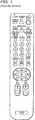
Ungeachtet der Tatsache, dass sich die Anzahl der Kanäle und der Umfang des zum Anschauen verfügbaren Inhalts dramatisch vergrößert haben, haben sich die durchgängig verfügbaren Nutzerschnittstellen, die Steuergerät Auswahlmöglichkeiten und die Grundstrukturen für die Fernsehgeräte über die letzten 30 Jahre hinweg nicht viel verändert. Gedruckte Programmführer stellen nach wie vor das vorherrschende Hilfsmittel zum Übermitteln der Programminformationen dar. Die mit mehreren Tasten versehene Fernbedienung mit Pfeilen nach oben und unten ist immer noch der am weitesten verbreitete Mechanismus zur Inhalts-/Kanal-Auswahl. Die Personen, welche die TV-Nutzerschnittstelle entwerfen und realisieren, haben auf das Anwachsen des verfügbaren Medieninhalts mit einer einfachen Erweiterung der vorhandenen Auswahlverfahren und Schnittstellenobjekte reagiert. So wurde die Anzahl der Zeilen in den gedruckten Programmführern erhöht, um mehr Kanäle unterzubringen. Die Anzahl der Tasten auf den Fernbedienungen wurde vergrößert, um die erweiterte Funktionalität und Handhabung von Inhalten zu unterstützen, wie es z. B. in
Über die Zunahme der Bandbreite und der Inhalte hinaus wird das Schnittstellenengpassproblem durch die Bündelung von Technologien verschärft. Die Verbraucher reagieren positiv auf die Möglichkeit des Erwerbs integrierter Systeme anstelle einer Anzahl von einzeln betreibbaren Komponenten. Ein Beispiel für diesen Trend ist die Kombination Fernsehen/Videorecorder/DVD, in der drei zuvor unabhängige Komponenten heute oft als eine integrierte Einheit verkauft werden. Es ist wahrscheinlich, dass sich dieser Trend fortsetzt, möglicherweise mit einem Endergebnis, dass die meisten, wenn nicht alle Kommunikationsgeräte, die heute in einem Haushalt anzutreffen sind, als eine integrierte Einheit, z. B. als eine Fernsehen/Videorecorder/DVD/Internetzugang/Radio/Stereo-Einheit, gebündelt werden. Selbst diejenigen, die weiterhin getrennte Komponenten erwerben, werden wahrscheinlich eine nahtlose Steuerung der getrennten Komponenten und ein Zusammenwirken zwischen ihnen anstreben. Mit dieser zunehmenden Bündelung kommt das Potenzial für mehr Komplexität in der Nutzerschnittstelle. Als zum Beispiel die sogenannten ”universellen” Fernbedienungseinheiten eingeführt wurden, um z. B. den Funktionsumfang der TV-Fernbedienungseinheiten und der Videorecorder-Fernbedienungseinheiten zu kombinieren, war normalerweise die Anzahl der Tasten auf diesen universellen Fernbedienungseinheiten größer als die Anzahl der Tasten auf der TV-Fernbedienungseinheit oder auf der Videorekorder-Fernbedienungseinheit allein. Diese hinzukommende Zahl von Tasten und der Funktionsumfang machen es sehr schwierig, irgendetwas zu steuern außer den einfachsten Aktionsarten eines TV-Geräts oder Videorecorders, ohne die Suche nach der richtigen Taste auf der Fernbedienung aufzunehmen. Häufig stellen diese universellen Fernbedienungen nicht genug Tasten bereit, um auf die vielen Steuerungsebenen oder die Merkmale zuzugreifen, die einzigartig für bestimmte Fernsehgeräte sind. In diesen Fällen wird die originale Geräte-Fernbedienungseinheit noch benötigt, und es bleiben die ursprünglichen Schwierigkeiten beim Umgang mit mehreren Fernbedienungen infolge der Nutzerschnittstellenprobleme, die sich aus der Komplexität der Bündelung ergeben. In einigen Fernbedienungseinheiten ist dieses Problem durch Hinzufügen von ”Soft”-Tasten behandelt worden, die mit den Expert-Befehlen programmiert werden können. Diese Soft-Tasten weisen manchmal zugehörige LCD-Displays auf, um ihre Wirkung anzuzeigen. Diese weisen auch den Mangel auf, dass sie schwer zu nutzen sind, ohne vom TV-Gerät weg auf die Fernbedienung zu schauen. Noch ein weiterer Mangel bei diesen Fernbedienungseinheiten ist die Verwendung von Betriebsarten, wenn versucht wird, die Anzahl der Tasten zu verringern. In diesen ”betriebsartangepassten” universellen Fernbedienungseinheiten gibt es eine spezielle Taste, um auszuwählen, ob die Fernbedienung mit dem TV-Gerät, dem DVD-Player, der Kabel-Set-Top-Box, dem Videorecorder usw. in Verbindung treten soll. Das erzeugt viele Einsatzprobleme einschließlich des Sendens von Befehlen an das falsche Gerät, wodurch der Nutzer gezwungen wird, auf die Fernbedienung zu schauen, um sicherzustellen, dass sie in der richtigen Betriebsart ist, und es stellt keinerlei Vereinfachung zur Integration von mehreren Geräten bereit. Die am weitesten entwickelte von diesen universellen Fernbedienungseinheiten liefert eine gewisse Integration, indem sie dem Nutzer ermöglicht, Abfolgen von Befehlen an mehrere Geräte in die Fernbedienung zu programmieren. Das ist eine derart komplizierte Aufgabe, dass viele Nutzer professionelle Einrichter beauftragen, ihre universellen Fernbedienungseinheiten zu programmieren.Beyond the increase in bandwidth and content, the interface bottleneck problem is exacerbated by the bundling of technologies. Consumers are responding positively to the possibility of acquiring integrated systems rather than a number of individually operable components. An example of this trend is the television / VCR / DVD combination, in which three previously independent components are often sold today as one integrated unit. It is likely that this trend will continue, possibly with the end result that most, if not all, of the communication devices that are present in a household today are integrated as one unit, e.g. B. as a television / VCR / DVD / Internet access / radio / stereo unit, bundled. Even those who continue to purchase separate components are likely to seek seamless control of the disparate components and interaction between them. With this increasing bundling comes the potential for more complexity in the user interface. For example, when the so-called "universal" remote control units were introduced to operate e.g. For example, to combine the functionality of the TV remote control units and the VCR remote control units, normally the number of buttons on these universal remote control units was greater than the number of buttons on the TV remote control unit or on the VTR remote control unit alone. This added number of buttons and features make it very difficult to control anything except the simplest types of action of a TV or VCR, without having to search for the right button on the remote. Often, these universal remote controls do not provide enough keys to access the many control levels or features unique to particular televisions. In these cases, the original device remote control unit is still needed, and the original difficulties in dealing with multiple remote controls remain due to user interface issues resulting from the complexity of the bundling. In some remote control units, this problem has been addressed by adding "soft" keys that can be programmed with the Expert commands. These soft keys sometimes have associated LCD displays to indicate their effect. These also have the defect that they are difficult to use without looking away from the TV set on the remote control. Yet another shortcoming of these remote units is the use of modes when trying to reduce the number of keys. In these "mode-matched" universal remote control units, there is a dedicated button to select if the remote control should contact the TV, DVD player, cable set-top box, VCR, etc. This creates many deployment problems, including sending commands to the wrong device, forcing the user to look at the remote to make sure it is in the correct mode, and it does not provide any simplification for integrating multiple devices. The most advanced of these universal remote control units provides some integration by allowing the user to program sequences of commands to multiple devices into the remote control. This is such a complicated task that many users hire professional installers to program their universal remote control units.
Es wurden auch einige Versuche unternommen, die Bildschirmschnittstelle zwischen dem Endnutzer und den Mediensystemen zu modernisieren. Unter anderen Nachteilen kranken diese Versuche jedoch typischerweise an einem Unvermögen, bequem zwischen großen Beständen von Medienelementen und kleinen Beständen von Medienelementen zu skalieren. Zum Beispiel können Schnittstellen, die sich auf Elementlisten stützen, für kleine Bestände von Medienelementen gut arbeiten, das Browsen für große Bestände von Medienelementen ist aber mühsam. Schnittstellen, die sich auf eine hierarchische Navigation (z. B. Baumstrukturen) stützen, können für große Bestände von Medienelementen schneller zu durchlaufen sein als Listenschnittstellen, sind aber nicht einfach anpassbar an kleine Bestände von Medienelementen. Dazu kommt, dass die Nutzer tendenziell das Interesse an den Auswahlvorgängen verlieren, in denen sich der Nutzer durch drei oder mehr Schichten in einer Baumstruktur zu bewegen hat. Für alle diese Fälle machen die heutigen Fernbedienungseinheiten diesen Auswahlvorgang sogar langwieriger, indem der Nutzer dazu gezwungen wird, die Up- und Down-Tasten wiederholt zu drücken, um in den Listen oder Hierarchien zu navigieren. Wenn Sprungsteuerungen zum Auswählen verfügbar sind, wie z. B. Page-Up und Page-Down, dann muss der Nutzer gewöhnlich auf die Fernsteuerung schauen, um diese speziellen Tasten zu finden, oder er muss dazu ausgebildet sein, dass er weiß, dass sie überhaupt vorhanden sind. Dementsprechend sind in der US-Patentanmeldung Serien-Nr. 10/768,432, mit dem Titel ”A Control Framework with a Zoomable Graphical User Interface for Organizing, Selecting and Launching Media Items”, eingereicht am 30. Januar 2004, Organisationsrahmenstrukturen, Techniken und Systeme vorgeschlagen worden, welche die Steuerung und die Bildschirmschnittstelle zwischen Nutzern und Mediensystemen vereinfachen wie auch den Auswahlvorgang beschleunigen, wobei es gleichzeitig den Dienstanbietern ermöglicht wird, einen Vorteil aus der Zunahme in der verfügbaren Bandbreite für die Endnutzerausrüstungen zu ziehen, was die Versorgung mit einer großen Zahl von Medienelementen und neuen Dienstleistungen für den Nutzer erleichtert.Some attempts have also been made to modernize the screen interface between the end user and the media systems. However, among other disadvantages, these attempts typically suffer from an inability to scale conveniently between large stocks of media assets and small collections of media assets. For example, interfaces that rely on element lists may work well for small media asset inventories, but browsing for large asset volumes is cumbersome. Interfaces relying on hierarchical navigation (eg tree structures) may be faster to pass through for large volumes of media assets than list interfaces, but are not easily adaptable to small footprints of media elements. On top of that, the users tend to lose interest in the selection processes in which the user has to move through three or more layers in a tree structure. For all these cases, today's remote control units make this selection process even more tedious, forcing the user to repeatedly press the up and down keys to navigate the lists or hierarchies. If jump controls are available for selection, such as: For example, page-up and page-down, the user usually has to look at the remote control to find those specific keys, or he must be trained to know that they are even present. Accordingly, in US patent application Ser. No. 10 / 768,432, entitled "A Control Framework with a Zoomable Graphical User Interface for Organizing, Selecting, and Launching Media Items," filed Jan. 30, 2004, has proposed organizational frameworks, techniques, and systems that control and display the interface between users Simplify and speed up the selection process, while allowing service providers to take advantage of the increase in available bandwidth for end-user equipment, which facilitates the provision of a large number of media items and new services to the user.
Von besonderem Interesse für diese Beschreibung sind die Fernbedienungsgeräte, die nutzbar sind, mit derartigen Rahmenstrukturen wie auch anderen Anwendungen und Systemen zu wechselwirken. Wie in der oben zitierten Anmeldung erwähnt ist, können verschiedene Typen von Fernbedienungsgeräten mit solchen Rahmenstrukturen verwendet werden, die zum Beispiel Rollkugeln, Zeigevorrichtungen vom ”Maus”-Typ, Lichtschreiber usw. einschließen. Eine weitere Gruppe von Fernbedienungsgeräten, die mit derartigen Rahmenstrukturen (und anderen Anwendungen) verwendet werden kann, sind die Freiraum-Zeigevorrichtungen. Der Ausdruck ”Freiraumanzeige” wird in dieser Beschreibung verwendet, um auf die Fähigkeit einer Eingabevorrichtung hinzuweisen, sich in drei (oder mehr) Dimensionen im freien Raum, z. B. vor einem Displaybildschirm, zu bewegen, und auf die dementsprechende Fähigkeit der Nutzerschnittstelle, diese Bewegungen unmittelbar in Nutzerschnittstellenbefehle zu übersetzen, z. B. in die Bewegung eines Zeigers auf einem Displaybildschirm. Die Übergabe von Daten zwischen der Freiraum-Zeigevorrichtung und einer weiteren Vorrichtung kann drahtlos oder über einen Draht erfolgen, der die Freiraum-Zeigevorrichtung und die andere Vorrichtung verbindet. Somit unterscheidet sich die ”Freiraumanzeige” z. B. von den herkömmlichen Computermaus-Anzeigetechniken, die eine Fläche, so z. B. eine Tischfläche oder ein Mauspad, als eine Kontaktfläche verwenden, von der die Relativbewegung der Maus in die Zeigerbewegung auf dem Computer-Displaybildschirm übertragen wird. Ein Beispiel für eine Freiraum-Zeigevorrichtung kann in der
In dem
Der Verwendungsspielraum, der mit den Freiraumanzeigern verbunden ist, erzeugt jedoch zusätzliche Probleme. Weil zum Beispiel im Allgemeinen keine Kontaktfläche vorhanden ist, auf der eine Freiraum-Zeigevorrichtung ruht, kann sich die Ausrichtung der handgeführten Steuervorrichtung von Nutzer zu Nutzer oder sogar von Einsatz zu Einsatz beträchtlich verändern. Wird eine Freiraum-Zeigevorrichtung zum Beispiel zum Steuern der Bewegung eines auf einem Bildschirm dargestellten Zeigers verwendet, dann wird eine bestimmte Abbildung zwischen der erfassten Bewegung der handgeführten Vorrichtung und der Bewegung des Zeigers auf dem Bildschirm ausgeführt.However, the latitude associated with the free space indicators creates additional problems. For example, because there is generally no contact surface on which a free space pointing device rests, the orientation of the handheld controller can vary considerably from user to user, or even from one mission to another. For example, if a free space pointing device is used to control the movement of a pointer displayed on a screen, then a particular mapping is made between the detected movement of the handheld device and the movement of the pointer on the screen.
Eine Technik zum Ausführen dieser Abbildung ist die Verwendung des Körpersystems der Vorrichtung als das Bezugssystem für das Abbilden der erfassten Bewegung der Freiraum-Zeigevorrichtung auf die beabsichtigte Bewegung des Zeigers. Der Begriff ”Körpersystem” bezieht sich auf einen Satz von Achsen, die mit dem Körper des bewegten Objekts verbunden sind, wie nachfolgend ausführlicher beschrieben wird. Die Verwendung des Körperbezugssystems zum Ausführen der Abbildung weist jedoch bestimmte Nachteile auf. Zum Beispiel ist es erforderlich, dass der Nutzer die Vorrichtung in einer bestimmten Ausrichtung hält, um die Zeigerbewegung zu erhalten, die er oder sie wünscht. Hält der Nutzer die Vorrichtung zum Beispiel an ihrer Seite fest und bewegt die Vorrichtung von links nach rechts, dann wird sich der Zeiger auf dem Bildschirm vertikal, nicht horizontal, bewegen.One technique for performing this mapping is to use the body system of the device as the reference system for mapping the detected movement of the free space pointing device to the intended movement of the pointer. The term "body system" refers to a set of axes associated with the body of the moving object, as described in more detail below. However, the use of the body reference system to perform the imaging has certain disadvantages. For example, the user is required to hold the device in a particular orientation to obtain the pointer movement he or she desires. For example, if the user holds the device by his side and moves the device from left to right, then the pointer on the screen will move vertically, not horizontally.
Entsprechend beschreibt die vorliegende Anmeldung Verfahren und Vorrichtungen zum Prozessieren von Daten, welche von einem Sensor oder mehreren Sensoren erhalten werden, auf eine Weise, welche diese und andere im Zusammenhang mit der herkömmlichen Freiraum-Zeigevorrichtung stehen, angeht. Accordingly, the present application describes methods and apparatus for processing data obtained from one or more sensors in a manner that is associated with these and others associated with the conventional free-space pointing device.
ZUSAMMENFASSUNGSUMMARY
Systeme und Verfahren gemäß der vorliegenden Erfindung beschreiben Freiraum-Zeigevorrichtungen, welche die Benutzbarkeit verbessern, in dem gemessene Bewegungsdaten von einem ersten Bezugssystem (zum Beispiel den Körper der Freiraum-Zeigevorrichtung) in ein zweites Bezugssystem (zum Beispiel das Bezugssystem eines Benutzers. Eine beispielhafte Ausführungsform der vorliegenden Erfindung entfernt Effekte, die im Zusammenhang mit einer Neigungsorientierung stehen, in welcher die Freiraum-Zeigevorrichtung durch einen Benutzer gehalten wird.Systems and methods according to the present invention describe free space pointing devices that improve usability in the measured motion data from a first frame of reference (e.g., the body of the free space pointing device) to a second frame of reference (e.g., a user's frame of reference The present invention eliminates effects associated with tilt orientation in which the free space pointing device is held by a user.
Gemäß einer beispielhaften Ausführungsform der vorliegenden Erfindung umfasst eine handgehaltene Zeigevorrichtung einen ersten Rotationssensor zum Bestimmen der Rotation der Zeigevorrichtung um eine erste Achse und zum Erzeugen einer dieser zugeordneten ersten Rotationsausgabe, einen zweiten Rotationssensor zum Bestimmen einer Rotation der Zeigevorrichtung um eine zweite Achse und zum Erzeugen einer dieser zugeordneten zweiten Rotationsausgabe, einen Beschleunigungsaufnehmer zum Bestimmen einer Beschleunigung der Zeigevorrichtung und zum Ausgeben einer dieser zugeordneten Beschleunigungsausgabe und eine Verarbeitungseinheit zum Erhalten der ersten und zweiten Rotationswertausgaben und der Beschleunigungswertausgabe, und zum: (a) Umwandeln der ersten und der zweiten Rotationswertausgabe und der Beschleunigungswertausgabe von einem Körper-Bezugssystem, welches der handgehaltenen Zeigevorrichtung zugeordnet ist, in ein Bezugssystem eines Benutzers, um Neigungseffekte zu entfernen, welche mit der Art verknüpft sind, mit welcher der Benutzer die handgehaltene Zeigevorrichtung hält; und (b) Bestimmen von Daten, welche x- und y-Koordinaten zugeordnet sind, welche wiederum der Bewegung eines Bildschirmcursors zugeordnet sind, wobei die Daten auf der umgewandelten ersten Rotationswertausgabe, der umgewandelten zweiten Rotationswertausgabe und der umgewandelten Beschleunigungswertausgabe beruhen, wobei der Schritt des Umwandelns die Bewegung des Bildschirmcursors im wesentlichen unabhängig von einer Orientierung macht, in welcher ein Benutzer die handgehaltene Vorrichtung hält.In accordance with an exemplary embodiment of the present invention, a hand-held pointing device includes a first rotation sensor for determining rotation of the pointing device about a first axis and producing a first rotation output associated therewith, a second rotation sensor for determining rotation of the pointing device about a second axis, and generating one and a processing unit for obtaining the first and second rotation value outputs and the acceleration value output, and for: (a) converting the first and second rotation value outputs and the acceleration value outputs from a body reference system associated with the hand-held pointing device into a user's frame of reference to remove tilting effects, as shown in FIG are associated with the type with which the user holds the hand-held pointing device; and (b) determining data associated with x and y coordinates associated with movement of a screen cursor, the data being based on the converted first rotation value output, the converted second rotation value output, and the converted acceleration value output, wherein the step of Transforming the movement of the screen cursor makes substantially independent of an orientation in which a user holds the hand-held device.
Gemäß einer weiteren beispielhaften Ausführungsform der vorliegenden Erfindung umfasst ein Verfahren zum Benutzen einer Freiraum-Zeigevorrichtung Schritte zum Detektieren der Bewegung der Freiraum-Zeigevorrichtung und zum Kompensieren der detektierten Bewegung durch Transformieren der detektierten Bewegung von einem Körper-Bezugssystem, welches mit der Freiraum-Zeigevorrichtung verknüpft ist, in ein Inertial-Bezugssystem.According to another exemplary embodiment of the present invention, a method of using a clearance pointing device includes steps of detecting the movement of the clearance pointing device and compensating for the detected motion by transforming the detected motion from a body reference system associated with the clearance pointing device is, in an inertial frame of reference.
Gemäß noch einer weiteren beispielhaften Ausführungsform der vorliegenden Erfindung umfasst eine Freiraum-Zeigevorrichtung wenigstens einen Sensor, um die Bewegung der Freiraum-Zeigevorrichtung zu detektieren, und eine Verarbeitungseinheit zum Kompensieren der detektierten Bewegung durch Transformieren der detektierten Bewegung von einem Körper-Bezugssystem, welches mit der Freiraum-Zeigevorrichtung verknüpft ist, in ein Inertial-Bezugssystem.In accordance with yet another exemplary embodiment of the present invention, a free space pointing device includes at least one sensor for detecting the movement of the free space pointing device, and a processing unit for compensating the detected motion by transforming the detected motion from a body reference frame associated with the Free-space pointing device is linked to an inertial frame of reference.
KURZE BESCHREIBUNG DER ZEICHNUNGENBRIEF DESCRIPTION OF THE DRAWINGS
Die beigefügten Zeichnungen veranschaulichen Ausführungsbeispiele der vorliegenden Erfindung, wobei:The accompanying drawings illustrate embodiments of the present invention wherein:
DETAILLIERTE BESCHREIBUNGDETAILED DESCRIPTION
Die nachfolgende detaillierte Beschreibung der Erfindung bezieht sich auf die beigefügten Zeichnungen. Gleiche Bezugszahlen in den verschiedenen Zeichnungen kennzeichnen dieselben oder ähnliche Elemente. Außerdem schränkt die nachfolgende detaillierte Beschreibung die Erfindung nicht ein. Stattdessen wird der Geltungsbereich der Erfindung durch die beigefügten Ansprüche festgelegt.The following detailed description of the invention refers to the attached drawings. Like reference numerals in the various drawings indicate the same or similar elements. In addition, the following detailed description does not limit the invention. Instead, the scope of the invention is defined by the appended claims.
Um für diese Erörterung einen gewissen Rahmen bereitzustellen, wird zuerst mit Bezugnahme auf
In diesem Ausführungsbeispiel enthält das Mediensystem
Das Entertainment-System
Wie in
Weitere Einzelheiten bezüglich dieses Entertainment-Systembeispiels und der damit verbundenen Grundstrukturen können in der oben zitierten, durch Inbezugnahme aufgenommenen US-Patentanmeldung ”A Control Framework with a Zoomable Graphical User Interface for Organizing, Selecting and Launching Media Items” gefunden werden. Alternativ können die Fernbedienungsvorrichtungen gemäß der vorliegenden Erfindung in Verbindung mit anderen Systemen, zum Beispiel Computersystemen, verwendet werden, die z. B. ein Display, einen Prozessor oder ein Speichersystem enthalten, oder mit verschiedenen anderen Systemen und Anwendungen.Further details regarding this entertainment system example and related basic structures can be found in the above cited, incorporated by reference US patent application "A Control Framework with a Zoomable Graphical User Interface for Organizing, Selecting and Launching Media Items". Alternatively, the remote control devices according to the present invention may be used in conjunction with other systems, for example computer systems, e.g. As a display, a processor or a storage system, or with various other systems and applications.
Wie im Hintergrund-Abschnitt erwähnt wurde, sind die Fernbedienungsvorrichtungen, die als Freiraumzeiger arbeiten, für die vorliegende Beschreibung von besonderem Interesse. Derartige Vorrichtungen ermöglichen die Überführung von Bewegung, z. B. Gesten, in Befehle an eine Nutzerschnittstelle. In
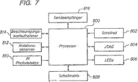
Wie in
Eine Herausforderung, mit welcher bei einer Realisierung der Beispiele für Freiraum-Zeigevorrichtungen
In
Die Ausgabe aus dem Beschleunigungswertaufnehmer
Die Skalen- und Offsetabweichungen des Beschleunigungswertaufnehmers
Über Skala und Offset hinaus können die vom Beschleunigungswertaufnehmer
Gemäß den Ausführungsbeispielen der vorliegenden Erfindung dient der Beschleunigungswertaufnehmer
Die abgetasteten Rotationsdaten
Die Offsetwerte offset(T) und dOffset können auf mehreren unterschiedlichen Wegen bestimmt werden. Wird zum Beispiel die Freiraum-Zeigevorrichtung
Ein Realisierungsbeispiel für die dOffset-Berechnung verwendet die kalibrierten Sensorausgaben, die tiefpassgefiltert sind. Die Stationärausgabe-Nachweisfunktion
Nach der Umwandlung/Kalibrierung am Block
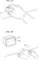
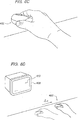
Um die Notwendigkeit einer Neigungskompensation gemäß den Ausführungsbeispielen der vorliegenden Erfindung besser zu verstehen, wird das Beispiel betrachtet, das in
Wenn der Nutzer demgegenüber die Freiraum-Zeigevorrichtung
Mit erneuter Bezugnahme auf ![]()
![]()
![]()
![]()
Sobald die kalibrierten Sensoranzeigewerte bezüglich der Linearbeschleunigung kompensiert worden sind, zu Anzeigewerten weiterverarbeitet worden sind, welche die Winkeldrehung der Freiraum-Zeigevorrichtung
Nachdem eine Prozessbeschreibung der als Beispiel dienenden Freiraum-Zeigevorrichtungen gemäß der vorliegenden Erfindung geliefert worden ist, veranschaulicht
In dem Ausführungsbeispiel von ![]()
![]()
Die Stationär-Nachweisfunktion
Ein weiteres Stationär-Nachweisverfahren gemäß den Ausführungsbeispielen der vorliegenden Erfindung bezieht das Umformen der Eingaben in die Frequenzebene ein, indem z. B. eine schnelle Fouriertransformation (FFT) an den Eingabedaten ausgeführt wird. Dann können die Daten analysiert werden, wobei z. B. Spitzenwertnachweisverfahren verwendet werden, um zu bestimmen, ob die Freiraum-Zeigevorrichtung
In den vorhergehenden Beispielen werden die Streuungen in der Frequenzdarstellung innerhalb eines speziellen Frequenzbereiches erfasst, wobei jedoch der aktuelle Frequenzbereich, der zu überwachen und zur Kennzeichnung des Zustandes der Freiraum-Zeigevorrichtung
Gemäß einem weiteren Ausführungsbeispiel der vorliegenden Erfindung kann der Stationär-Nachweismechanismus
Die Zustandsübergänge können anhand einer Anzahl unterschiedlicher Bedingungen bestimmt werden, die auf den interpretierten Sensorausgaben beruhen. Beispiele für die Bedingungskriterien schließen die Streuung der interpretierten Signale über ein Zeitfenster ein, zur Bestimmung der Zustandsübergänge können der Schwellenwert zwischen einem Bezugswert und dem interpretierten Signal über ein Zeitfenster, der Schwellenwert zwischen einem Bezugswert und dem gefilterten interpretierten Signal über ein Zeitfenster sowie der Schwellenwert zwischen einem Bezugswert und dem interpretierten Signal von einer Startzeit an verwendet werden. Es können alle oder eine beliebige Kombination von diesen Bedingungskriterien verwendet werden, um die Zustandsübergänge auszulösen. Alternativ können auch andere Kriterien verwendet werden. Gemäß einem Ausführungsbeispiel der vorliegenden Erfindung kommt es zu einem Übergang vom Zustand INAKTIV in den Zustand AKTIV, wenn entweder (1) ein Mittelwert der Sensorausgabe(n) über ein Zeitfenster größer als ein vorgegebener Schwellenwert (vorgegebene Schwellenwerte) ist oder (2) eine Streuung von Werten der Sensorausgabe(n) über ein Zeitfenster größer als ein vorgegebener Schwellenwert (vorgegebene Schwellenwerte) ist oder (3) ein momentanes Delta zwischen den Sensorwerten größer als ein vorgegebener Schwellenwert ist.The state transitions can be determined from a number of different conditions based on the interpreted sensor outputs. Examples of the conditional criteria include the dispersion of the interpreted signals over a time window, for determining the state transitions the threshold between a reference value and the interpreted signal over a time window, the threshold between a reference value and the filtered interpreted signal over a time window and the threshold between a reference value and the interpreted signal from a start time. Any or any combination of these condition criteria can be used to trigger the state transitions. Alternatively, other criteria may be used. According to an embodiment of the present invention, a transition from the INACTIVE state to the ACTIVE state occurs when either (1) an average of the sensor output (s) over a time window is greater than a predetermined threshold (predetermined thresholds) or (2) a spread of values of the sensor output (s) over a time window is greater than a predetermined threshold (predetermined thresholds) or (3) a current delta between the sensor values is greater than a predetermined threshold.
Der Zustand INAKTIV erlaubt dem Stationär-Nachweismechanismus
Die Freiraum-Zeigevorrichtung
Die Zustände STABIL und STATIONÄR legen Zeiten fest, während derer die Freiraum-Zeigevorrichtung
Beginnt sich die Freiraum-Zeigevorrichtung
Beim Empfang eines weiteren Befehls oder wenn sich die Freiraum-Zeigevorrichtung
Die Bedingungen für die Zustandsübergänge können symmetrisch sein oder können sich unterscheiden. So kann der Schwellenwert, der mit der Bedingungaktiv→inaktiv verbunden ist, der gleiche sein wie (oder ein anderer sein als) der (die) mit der Bedingunginaktiv→aktiv verbundene (n) Schwellenwert(e). Das ermöglicht es den Freiraum-Zeigevorrichtungen gemäß der vorliegenden Erfindung, die Nutzereingabe genauer zu erfassen. Zum Beispiel ermöglichen die Ausführungsbeispiele, die eine Realisierung der Zustandsmaschine einschließen, dass unter anderem der Schwellenwert für den Übergang in einen stationären Zustand ein anderer ist als der Schwellenwert für den Übergang aus einem stationären Zustand heraus.The conditions for the state transitions may be symmetric or may differ. Thus, the threshold associated with the Active → inactive condition may be the same as (or other than) the ( inactive) → actively connected threshold (s). This enables the free space pointing devices according to the present invention to more accurately detect the user input. For example, the embodiments involving realization of the state machine allow, inter alia, the threshold for transition to a steady state to be different than the threshold for transition from a steady state.
Das Erreichen oder Verlassen eines Zustandes kann auch dazu verwendet werden, andere Vorrichtungsfunktionen einzuleiten. Zum Beispiel kann die Nutzerschnittstelle basierend auf einem Übergang von einem beliebigen Zustand in den AKTIV-Zustand zugeschaltet werden. Umgekehrt kann die Freiraum-Zeigevorrichtung und/oder die Nutzerschnittstelle abgeschaltet werden (oder in einen Schlaf-Modus übergehen), wenn die Freiraum-Zeigevorrichtung von AKTIV oder STABIL zu STATIONÄR oder INAKTIV übergeht. Alternativ kann der Zeiger
Wie oben erwähnt wurde, werden in den Ausführungsbeispielen der vorliegenden Erfindung die Bewegungsdaten, die von dem(den) Sensor(en) in der Freiraum-Zeigevorrichtung empfangen wurden, bearbeitet, um diese Daten von dem Bezugssystem des Körpers der Freiraum-Zeigevorrichtung in ein anderes Bezugssystem, z. B. das Bezugssystem des Nutzers, umzuwandeln. In dem Anwendungsbeispiel einer Freiraum-Zeigevorrichtung, die zum Steuern einer auf einem Bildschirm, z. B. einem Fernseher, dargestellten Nutzerschnittstelle verwendet wird, könnte das Bezugssystem des Nutzers ein Koordinatensystem sein, das mit dem Fernsehbildschirm verbunden ist. Unabhängig davon verbessert die Überführung der Daten von dem Körperbezugssystem in ein anderes Bezugssystem die Brauchbarkeit der handgeführten Vorrichtung dadurch, dass sich ein Betrieb ergibt, der eher aus der Perspektive des Nutzers als aus der Perspektive der Vorrichtung erfolgt. Bewegt der Nutzer seine Hand vor einem Display von links nach rechts, während er die Freiraum-Zeigevorrichtung hält, so wird sich der Zeiger unabhängig von der Ausrichtung der Freiraum-Zeigevorrichtung in der Richtung von links nach rechts bewegen. As mentioned above, in the embodiments of the present invention, the movement data received from the sensor (s) in the free space pointing device is processed to transfer that data from the reference system of the free space pointing device body to another Reference system, e.g. B. the reference system of the user to convert. In the application example of a free-space pointing device, which is used to control on-screen display, e.g. As a television, displayed user interface is used, the reference system of the user could be a coordinate system that is connected to the TV screen. Regardless, transferring the data from the body reference system to another reference system improves the usefulness of the handheld device by providing an operation that is from the user's perspective rather than the device's perspective. If the user moves his hand in front of a display from left to right while holding the free-space pointing device, the pointer will move in the left-to-right direction regardless of the orientation of the free-space pointing device.
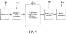
Um diese Darlegung zu vereinfachen, ist in
Im Block
In diesem Ausführungsbeispiel wird angenommen, dass das Nutzerbezugssystem stationär ist und eine feste Ausrichtung aufweist, obwohl Fachleute anerkennen werden, dass diese Technik gemäß der vorliegenden Erfindung leicht auf die Fälle erweitert werden kann, in denen das Bezugssystem des Nutzers nicht stationär ist, indem entweder direkt auf das zeitlich veränderliche Achsensystem transformiert wird oder indem zuerst auf ein stationäres Achsensystem umgewandelt und dann auf das sich bewegende Achsensystem umgewandelt wird. Für das stationäre, eine feste Ausrichtung aufweisende Nutzer-Bezugssystembeispiel kann die Umwandlung aus dem Körperachsensystem in das Nutzerachsensystem unter Verwendung der nachfolgenden Gleichungen ausgeführt werden:
Rotate den Quaternion-Rotationsoperator derart darstellt, dass Rotate(A, Q) gleich Q* AQ ist, wobei Q* die Quaternion-Konjugierte und der Vektor A eine Quaternion mit der komplexen Komponente gleich A und der reellen Komponente gleich 0 ist;
Pu die Position in dem Nutzerbezugssystem ist;
Pb die Position in dem Vorrichtungsbezugssystem ist;
' die Ableitung bezeichnet. Deshalb ist Pu' die Ableitung der Position im Nutzerbezugssystem, welche die Geschwindigkeit im Nutzerbezugssystem ist;
Wu ist die Winkelgeschwindigkeit der Vorrichtung in Körperwinkeln im Nutzerbezugssystem;
Wb ist die Winkelgeschwindigkeit der Vorrichtung in Körperwinkeln im Körperachsensystem der Vorrichtung;
Pdelta ist die Differenz zwischen dem Ursprung des Nutzerbezugssystems und des Körperbezugssystems im Koordinatensystem des Nutzerbezugssystems;
Q ist die normierte Rotationsquaternion, welche die Drehung aus dem Körperachsensystem in das Nutzerachsensystem darstellt. Da Q* die Rotationsquaternion für die Drehung aus dem Nutzerachsensystem in das Körperachsensystem ist, könnte Q durch R* ersetzt werden, wobei R die Drehung aus dem Nutzerachsensystem in das Körperachsensystem ist. Es wird angemerkt, dass Q in mehreren äquivalenten Formen dargestellt werden kann, welche die Eulerschen Winkel und die Richtungscosinusmatrix (DCM) enthalten, und dass sich die obigen Gleichungen in ihren äquivalenten Formen, die auf den verschiedenen Darstellungen von Q beruhen, geringfügig unterscheiden können.
Rotate represents the quaternion rotation operator such that rotates (A, Q) equals Q * AQ, where Q * is the quaternion conjugate and the vector A is a quaternion with the complex component equal to A and the real component equal to 0;
Pu is the location in the user reference system;
Pb is the position in the device reference system;
'designates the derivative. Therefore, Pu 'is the derivative of the position in the user reference system, which is the speed in the user reference system;
Wu is the angular velocity of the device in body angles in the user reference system;
Wb is the angular velocity of the device at body angles in the body axis system of the device;
Pdelta is the difference between the origin of the user reference system and the body reference system in the user reference system coordinate system;
Q is the normalized rotation quaternion, which represents the rotation from the body axis system to the user axis system. Since Q * is the rotation quaternion for rotation from the user axis system to the body axis system, Q could be replaced by R *, where R is the rotation from the user axis system into the body axis system. It is noted that Q can be represented in several equivalent forms containing the Euler angles and the direction cosine matrix (DCM), and that the equations above can be slightly different in their equivalent forms based on the different representations of Q.
Während des Betriebs schätzt die Vorrichtung in einer von der Realisierung abhängigen Weise Q ab, um diese Transformation auszuführen. Ein oben beschriebenes Realisierungsbeispiel bezieht die Kompensation hinsichtlich der Neigung (d. h. der Veränderungen in der x-Achsen-Querneigung der Freiraum-Zeigevorrichtung basierend auf der Art, wie es von einem Nutzer gehalten wird) ein. Die Ausrichtung wird berechnet, indem zuerst die Beschleunigungskomponente infolge der Erdanziehung im Körperachsensystem Ab abgeschätzt wird. Gemäß Festlegung wird der Beschleunigungsvektor infolge der Erdanziehung im Nutzerachsensystem Ag gleich [0, 0, –1] gesetzt. Da die Erdanziehung nicht den Kurs (Drehung um die z-Achse) abschätzen kann, wird die Körperachsensystem-Abschätzung für den Kurs verwendet. Deshalb weist die Rotationsquaternion eine Drehachse in der Ebene z = 0 auf. Es folgt eines von mehreren äquivalenten Verfahren für das Berechnen der Rotationsquaternion:
Wenn sich die Vorrichtung nicht bewegt, dann sind im Allgemeinen Pu', Pu'', Wu und Wu'' alle gleich 0. In diesem Ausführungsbeispiel werden Pb'' und Wb gemessen. Obwohl es eine unendliche Zahl von Drehungen Q gibt, kann die Minimaldrehung aus dem verfügbaren Satz ausgewählt und zur Abschätzung von Wu auf der Grundlage von Wb verwendet werden. Alternativ kann Q unter Verwendung einer angenommenen Start-Offsetausrichtung Q0 berechnet werden, indem Wb über die Zeit integriert wird, wie unten unter Verwendung des Diskretzeitintegrals gezeigt ist:
Es könnte eine Vielzahl verschiedener Sensoren eingesetzt werden, solange sie die Bewegung mit Bezug auf den Körper der Vorrichtung messen. Sensorbeispiele schließen Beschleunigungswertaufnehmer, Rotationssensoren, Kreiselgeräte, Magnetometer und Kameras ein. Das Nutzerachsensystem braucht nicht stationär zu sein. Wird das Nutzerbezugssystem zum Beispiel als der Unterarm des Nutzers ausgewählt, dann würde die Vorrichtung nur auf die Handgelenk- und Fingerbewegung reagieren. A variety of different sensors could be used as long as they measure the movement with respect to the body of the device. Sensor examples include acceleration transducers, rotation sensors, gyroscopes, magnetometers, and cameras. The user axis system does not need to be stationary. For example, if the user reference system is selected as the user's forearm, the device would only respond to the wrist and finger movement.
Fachleute werden erkennen, dass für die Bezugssystemtransformationen die in dieser Erfindung beschrieben sind, die Kommutativeigenschaft gilt. Deshalb kann die Reihenfolge der mathematschen Operationen verändert werden, ohne dass es eine wesentlich Auswirkung auf die hier beschriebene Erfindung hat. Außerdem können viele Bewegungsverarbeitungsalgorithmen in beiden Bezugssystemen gleichwertig arbeiten, insbesondere wenn das Nutzerachsensystem als stationär mit einer konstanten Ausrichtung gewählt wird.Those skilled in the art will recognize that for the reference system transformations described in this invention, the commutative property applies. Therefore, the order of mathematical operations can be changed without having a significant effect on the invention described herein. In addition, many motion processing algorithms can work equally well in both frames of reference, especially if the user axis system is chosen to be stationary with a constant orientation.
Über die Anwenderfreundlichkeit hinausgehend können die Bezugssystemtransformationen gemäß diesem Ausführungsbeispiel der vorliegenden Erfindung auch dazu verwendet werden, um anderen Anforderungen an die Realisierungen handgeführter Vorrichtungen gerecht zu werden. Wenn zum Beispiel ein Sensor (wie z. B. ein Beschleunigungswertaufnehmer) nicht genau im Rotationszentrum des Körperbezugssystems angeordnet ist, dann wird die gemessene Beschleunigung sowohl die Beschleunigung des Achsensystems als auch die Beschleunigungskomponenten infolge der Rotation des Achsensystems enthalten. Daher kann die gemessene Beschleunigung zuerst auf einen anderen Zielaufstellungsort im Körperachsensystem der Vorrichtung transformiert werden, wobei die folgende Beziehung verwendet wird:
Unglücklicherweise weisen verschiedene Nutzer unterschiedliche Werte für R auf. Zum Beispiel kann der eine Nutzer seine handgeführte Vorrichtung einsetzen, indem er seinen Ellbogen dreht, während ein anderer Nutzer seine Vorrichtung durch Drehen seines Handgelenks einsetzen kann. Darüber hinaus weisen die Personen Handgelenke und Unterarme unterschiedlicher Größe auf. Für eine verbesserte Benutzbarkeit wird in diesem Ausführungsbeispiel des Handgeräts R dynamisch berechnet und der Körpernullpunkt derart bewegt, dass er minimale Beschleunigungskomponenten infolge der Winkelbewegung aufweist. Im Ausführungsbeispiel wird R abgeschätzt, indem R als [Rx, 0, 0] festgelegt und nach Rx aufgelöst wird, wobei Akörper – Rotate[Ag, Q] verwendet und minimiert wird. Es wird angemerkt, dass viele numerische Verfahren existieren einschließlich der rekursiven kleinsten Quadrate und des Kalman-Filterns, mit denen eine Minimierung ausgeführt werden kann, um Rx zu berechnen.Unfortunately, different users have different values for R. For example, one user may use his handheld device by turning his elbow while another user may insert his device by turning his wrist. In addition, the persons have wrists and lower arms of different sizes. For improved usability in this embodiment of the handset R is calculated dynamically and the body zero point is moved so that it has minimal acceleration components due to the angular movement. In the embodiment, R is estimated by setting R as [Rx, 0, 0] and resolving to Rx using and minimizing Akobe rotates [Ag, Q]. It is noted that many numerical methods exist, including the recursive least squares and Kalman filtering, with which minimization can be performed to compute Rx.
Basierend auf den obigen Darlegungen wird eingeschätzt, dass die vorliegende Erfindung verschiedene Techniken zum Abbilden der erfassten Bewegung einer handgeführten Vorrichtung von einem Bezugssystem (z. B. einem Körperbezugssystem) in ein anderes Bezugssystem (z. B. ein Bezugssystem eines Nutzers) beschreibt. Diese Abbildungen können unabhängig von anderen Abbildungen sein, die mit dem Einsatz der handgeführten Vorrichtung verbunden sind, z. B. die Abbildung der erfassten Bewegung auf die Zeigerbewegung, oder sie können mit ihnen kombiniert werden. Außerdem können die Transformationen gemäß der vorliegenden Erfindung ausgeführt werden, um die erfasste Bewegung in allen drei Dimensionen, für die Translationsbewegung und die Rotationsbewegung oder eine beliebige Untermenge davon, aus der Perspektive entweder der Eingabeseite der Bewegungsgleichung oder der Ausgabeseite zu transformieren. Darüber hinaus kann die Auswahl des Bezugssystems, in welches die erfasste Bewegung abgebildet oder transformiert wird, auf mehreren unterschiedlichen Wegen erfolgen. Ein oben gegebenes Beispiel stellt dar, dass das zweite Bezugssystem ein Bezugssystem eines Nutzers ist, das mit der Neigung der Vorrichtung verknüpft ist, es sind jedoch viele andere Abänderungen möglich. Zum Beispiel kann der Nutzer sein gewünschtes Bezugssystem auswählen, dessen Einstellung in dem Handgerät als eine von mehreren Nutzerpräferenzen im Handgerät gespeichert und zum Ausführen der Transformation verwendet werden kann. Das zweite Bezugssystem kann basierend auf einer beliebigen Zahl von Techniken ausgewählt werden. Das zweite Bezugssystem kann ausgewählt werden auf Basis eines ausdrücklichen Befehls (z. B. Wahl einer Taste oder Nutzerschnittstelle) oder automatisch durch Nutzererkennung, die dadurch gegeben ist, dass die Vorrichtung Muster, die Zitterbewegung und andere biometrische Größen verwendet.Based on the above, it will be appreciated that the present invention describes various techniques for mapping the detected motion of a hand-held device from one reference system (eg, a body reference system) to another reference system (eg, a user's frame of reference). These illustrations may be independent of other illustrations associated with the use of the handheld device, e.g. Example, the mapping of the detected movement on the pointer movement, or they can be combined with them. In addition, the transformations according to the present invention may be performed to transform the detected motion in all three dimensions, for the translational motion and the rotational motion or any subset thereof, from the perspective of either the input side of the equation of motion or the output side. In addition, the selection of the reference system into which the detected motion is mapped or transformed can be done in several different ways. An example given above illustrates that the second frame of reference is a user's frame of reference associated with the tilt of the device however many other modifications possible. For example, the user may select his desired frame of reference, the setting of which may be stored in the handset as one of several user preferences in the handset and used to perform the transformation. The second frame of reference can be selected based on any number of techniques. The second frame of reference may be selected based on an explicit command (eg, choosing a button or user interface) or automatically by user recognition given by the device using patterns, dithering, and other biometric quantities.
Außerdem ist die vorliegende Erfindung, obwohl einige der oben beschriebenen Ausführungsbeispiele mit Daten im Geschwindigkeitsbereich arbeiten, nicht derart eingeschränkt. Das Abbilden oder die Transformation gemäß vorliegender Erfindung kann alternativ oder zusätzlich zum Beispiel an den Positions- oder Beschleunigungsdaten ausgeführt werden und kann für die Translationsbewegung, die Rotationsbewegung oder beide erfolgen. Auch der Verarbeitungsablauf ist nicht kritisch. Wenn die handgeführte Vorrichtung zum Beispiel zur Ausgabe von Gestenbefehlen verwendet wird, dann kann zuerst die Abbildung und dann die Geste bestimmt werden oder die Geste zuerst bestimmt und dann die Abbildung ausgeführt werden.In addition, although some of the above-described embodiments operate on data in the speed domain, the present invention is not so limited. The mapping or transformation of the present invention may alternatively or additionally be performed, for example, on the position or acceleration data, and may be for translational, rotational, or both. Also, the processing is not critical. For example, if the handheld device is used to issue gesture commands, then the image and then the gesture may be determined first or the gesture first determined and then the image performed.
Die oben beschriebenen Ausführungsbeispiele sind in jeder Hinsicht zur Veranschaulichung statt zur Einschränkung der vorliegenden Erfindung vorgesehen. Somit ist die vorliegende Erfindung zu vielen Veränderungen in der genauen Realisierung geeignet, die durch einen Fachmann aus der hier enthaltenen Beschreibung abgeleitet werden können. Obwohl die vorausgehenden Ausführungsbeispiele unter anderem den Einsatz von Trägheitssensoren zum Erfassen der Bewegung einer Vorrichtung beschreiben, können zum Beispiel andere Sensortypen (z. B. Ultraschall, magnetisch oder optisch) anstelle der oder zusätzlich zu den Trägheitssensoren in Verbindung mit der oben beschriebenen Signalverarbeitung verwendet werden. Alle derartigen Veränderungen und Abwandlungen werden als unter den Gedanken und den Schutzbereich der vorliegenden Erfindung liegend angesehen, der durch die nachfolgenden Ansprüche festgelegt ist. Kein Element, Vorgang oder keine Anweisung, die in der Beschreibung der vorliegenden Anmeldung verwendet wird, sollte als kritisch oder wesentlich für die Erfindung angesehen werden, es sei denn, sie werden ausdrücklich als solche beschrieben. Außerdem ist beabsichtigt, dass der Artikel ”ein” hier so verwendet wird, dass ein oder mehrere Objekte einbezogen sind.The embodiments described above are provided in all respects for purposes of illustration rather than limitation of the present invention. Thus, the present invention is susceptible to many changes in the precise implementation that may be derived by one of ordinary skill in the art from the description contained herein. For example, while the foregoing embodiments describe the use of inertial sensors to detect movement of a device, other types of sensors (eg, ultrasound, magnetic, or optical) may be used in place of or in addition to the inertial sensors in conjunction with the signal processing described above , All such changes and modifications are considered to be within the spirit and scope of the present invention as defined by the following claims. No element, act or instruction used in the description of the present application should be considered critical or essential to the invention unless expressly described as such. It is also intended that the term "a" be used here to include one or more objects.
ZITATE ENTHALTEN IN DER BESCHREIBUNG QUOTES INCLUDE IN THE DESCRIPTION
Diese Liste der vom Anmelder aufgeführten Dokumente wurde automatisiert erzeugt und ist ausschließlich zur besseren Information des Lesers aufgenommen. Die Liste ist nicht Bestandteil der deutschen Patent- bzw. Gebrauchsmusteranmeldung. Das DPMA übernimmt keinerlei Haftung für etwaige Fehler oder Auslassungen.This list of the documents listed by the applicant has been generated automatically and is included solely for the better information of the reader. The list is not part of the German patent or utility model application. The DPMA assumes no liability for any errors or omissions.
Zitierte PatentliteraturCited patent literature
- US 5440326 [0009, 0010] US 5440326 [0009, 0010]
Claims (16)
Applications Claiming Priority (6)
| Application Number | Priority Date | Filing Date | Title |
|---|---|---|---|
| US56644404P | 2004-04-30 | 2004-04-30 | |
| US566444P | 2004-04-30 | ||
| US61257104P | 2004-09-23 | 2004-09-23 | |
| US612571P | 2004-09-23 | ||
| US64141005P | 2005-01-05 | 2005-01-05 | |
| US641410P | 2005-01-05 |
Publications (1)
| Publication Number | Publication Date |
|---|---|
| DE202005022038U1 true DE202005022038U1 (en) | 2012-07-12 |
Family
ID=35320764
Family Applications (1)
| Application Number | Title | Priority Date | Filing Date |
|---|---|---|---|
| DE202005022038U Expired - Lifetime DE202005022038U1 (en) | 2004-04-30 | 2005-05-02 | Free space pointing devices with slope compensation and improved usability |
Country Status (11)
| Country | Link |
|---|---|
| US (4) | US7158118B2 (en) |
| EP (1) | EP1741088B1 (en) |
| JP (3) | JP5053078B2 (en) |
| KR (1) | KR101192514B1 (en) |
| AT (1) | ATE550709T1 (en) |
| DE (1) | DE202005022038U1 (en) |
| DK (1) | DK2337016T3 (en) |
| ES (2) | ES2664472T3 (en) |
| IN (1) | IN2014DN09404A (en) |
| PL (1) | PL1741088T3 (en) |
| WO (1) | WO2005108119A2 (en) |
Families Citing this family (355)
| Publication number | Priority date | Publication date | Assignee | Title |
|---|---|---|---|---|
| US7749089B1 (en) | 1999-02-26 | 2010-07-06 | Creative Kingdoms, Llc | Multi-media interactive play system |
| US7780967B2 (en) * | 2000-02-08 | 2010-08-24 | Allergan, Inc. | Reduced toxicity Clostridial toxin pharmaceutical compositions |
| US7878905B2 (en) | 2000-02-22 | 2011-02-01 | Creative Kingdoms, Llc | Multi-layered interactive play experience |
| US6761637B2 (en) | 2000-02-22 | 2004-07-13 | Creative Kingdoms, Llc | Method of game play using RFID tracking device |
| US7445550B2 (en) | 2000-02-22 | 2008-11-04 | Creative Kingdoms, Llc | Magical wand and interactive play experience |
| US7066781B2 (en) | 2000-10-20 | 2006-06-27 | Denise Chapman Weston | Children's toy with wireless tag/transponder |
| US6990639B2 (en) | 2002-02-07 | 2006-01-24 | Microsoft Corporation | System and process for controlling electronic components in a ubiquitous computing environment using multimodal integration |
| US6967566B2 (en) | 2002-04-05 | 2005-11-22 | Creative Kingdoms, Llc | Live-action interactive adventure game |
| US20070066396A1 (en) | 2002-04-05 | 2007-03-22 | Denise Chapman Weston | Retail methods for providing an interactive product to a consumer |
| US7033176B2 (en) * | 2002-07-17 | 2006-04-25 | Powergrid Fitness, Inc. | Motion platform system and method of rotating a motion platform about plural axes |
| US8797260B2 (en) | 2002-07-27 | 2014-08-05 | Sony Computer Entertainment Inc. | Inertially trackable hand-held controller |
| US8686939B2 (en) * | 2002-07-27 | 2014-04-01 | Sony Computer Entertainment Inc. | System, method, and apparatus for three-dimensional input control |
| US20060256081A1 (en) * | 2002-07-27 | 2006-11-16 | Sony Computer Entertainment America Inc. | Scheme for detecting and tracking user manipulation of a game controller body |
| US8313380B2 (en) | 2002-07-27 | 2012-11-20 | Sony Computer Entertainment America Llc | Scheme for translating movements of a hand-held controller into inputs for a system |
| US9393487B2 (en) | 2002-07-27 | 2016-07-19 | Sony Interactive Entertainment Inc. | Method for mapping movements of a hand-held controller to game commands |
| US10086282B2 (en) * | 2002-07-27 | 2018-10-02 | Sony Interactive Entertainment Inc. | Tracking device for use in obtaining information for controlling game program execution |
| US7760248B2 (en) | 2002-07-27 | 2010-07-20 | Sony Computer Entertainment Inc. | Selective sound source listening in conjunction with computer interactive processing |
| US20060282873A1 (en) * | 2002-07-27 | 2006-12-14 | Sony Computer Entertainment Inc. | Hand-held controller having detectable elements for tracking purposes |
| US8570378B2 (en) | 2002-07-27 | 2013-10-29 | Sony Computer Entertainment Inc. | Method and apparatus for tracking three-dimensional movements of an object using a depth sensing camera |
| US7782297B2 (en) * | 2002-07-27 | 2010-08-24 | Sony Computer Entertainment America Inc. | Method and apparatus for use in determining an activity level of a user in relation to a system |
| US9474968B2 (en) * | 2002-07-27 | 2016-10-25 | Sony Interactive Entertainment America Llc | Method and system for applying gearing effects to visual tracking |
| US9682319B2 (en) * | 2002-07-31 | 2017-06-20 | Sony Interactive Entertainment Inc. | Combiner method for altering game gearing |
| US7674184B2 (en) | 2002-08-01 | 2010-03-09 | Creative Kingdoms, Llc | Interactive water attraction and quest game |
| US20070155589A1 (en) * | 2002-12-04 | 2007-07-05 | Philip Feldman | Method and Apparatus for Operatively Controlling a Virtual Reality Scenario with an Isometric Exercise System |
| US20080146336A1 (en) * | 2002-12-04 | 2008-06-19 | Philip Feldman | Exercise Gaming Device and Method of Facilitating User Exercise During Video Game Play |
| US7727117B2 (en) * | 2002-12-04 | 2010-06-01 | Ialabs-Ca, Llc | Method and apparatus for operatively controlling a virtual reality scenario with a physically demanding interface |
| US7699755B2 (en) * | 2002-12-04 | 2010-04-20 | Ialabs-Ca, Llc | Isometric exercise system and method of facilitating user exercise during video game play |
| US9177387B2 (en) * | 2003-02-11 | 2015-11-03 | Sony Computer Entertainment Inc. | Method and apparatus for real time motion capture |
| US9446319B2 (en) | 2003-03-25 | 2016-09-20 | Mq Gaming, Llc | Interactive gaming toy |
| US8072470B2 (en) | 2003-05-29 | 2011-12-06 | Sony Computer Entertainment Inc. | System and method for providing a real-time three-dimensional interactive environment |
| US10279254B2 (en) | 2005-10-26 | 2019-05-07 | Sony Interactive Entertainment Inc. | Controller having visually trackable object for interfacing with a gaming system |
| US7874917B2 (en) | 2003-09-15 | 2011-01-25 | Sony Computer Entertainment Inc. | Methods and systems for enabling depth and direction detection when interfacing with a computer program |
| US8323106B2 (en) * | 2008-05-30 | 2012-12-04 | Sony Computer Entertainment America Llc | Determination of controller three-dimensional location using image analysis and ultrasonic communication |
| WO2005031502A2 (en) * | 2003-09-22 | 2005-04-07 | Kim Hyeung-Yun | Methods for monitoring structural health conditions |
| US7489299B2 (en) | 2003-10-23 | 2009-02-10 | Hillcrest Laboratories, Inc. | User interface devices and methods employing accelerometers |
| US7826641B2 (en) * | 2004-01-30 | 2010-11-02 | Electronic Scripting Products, Inc. | Apparatus and method for determining an absolute pose of a manipulated object in a real three-dimensional environment with invariant features |
| US7961909B2 (en) * | 2006-03-08 | 2011-06-14 | Electronic Scripting Products, Inc. | Computer interface employing a manipulated object with absolute pose detection component and a display |
| US9229540B2 (en) | 2004-01-30 | 2016-01-05 | Electronic Scripting Products, Inc. | Deriving input from six degrees of freedom interfaces |
| US8629836B2 (en) | 2004-04-30 | 2014-01-14 | Hillcrest Laboratories, Inc. | 3D pointing devices with orientation compensation and improved usability |
| EP1743322A4 (en) * | 2004-04-30 | 2008-04-30 | Hillcrest Lab Inc | Methods and devices for removing unintentional movement in free space pointing devices |
| WO2005109847A2 (en) * | 2004-04-30 | 2005-11-17 | Hillcrest Laboratories, Inc. | Methods and devices for identifying users based on tremor |
| EP1759529A4 (en) | 2004-04-30 | 2009-11-11 | Hillcrest Lab Inc | Free space pointing devices and method |
| ES2664472T3 (en) * | 2004-04-30 | 2018-04-19 | Idhl Holdings, Inc. | Free space signaling devices with tilt compensation and improved ease of use |
| US7746321B2 (en) * | 2004-05-28 | 2010-06-29 | Erik Jan Banning | Easily deployable interactive direct-pointing system and presentation control system and calibration method therefor |
| CA2578653A1 (en) | 2004-07-29 | 2006-02-09 | Kevin Ferguson | A human movement measurement system |
| US9900669B2 (en) | 2004-11-02 | 2018-02-20 | Pierre Touma | Wireless motion sensor system and method |
| US9317108B2 (en) * | 2004-11-02 | 2016-04-19 | Pierre A. Touma | Hand-held wireless electronic device with accelerometer for interacting with a display |
| WO2006058129A2 (en) | 2004-11-23 | 2006-06-01 | Hillcrest Laboratories, Inc. | Semantic gaming and application transformation |
| JP5080273B2 (en) | 2005-01-07 | 2012-11-21 | クアルコム,インコーポレイテッド | Tilt sensor based on optical flow |
| US7864159B2 (en) | 2005-01-12 | 2011-01-04 | Thinkoptics, Inc. | Handheld vision based absolute pointing system |
| KR100948095B1 (en) * | 2005-02-24 | 2010-03-16 | 노키아 코포레이션 | Motion-input device for a computing terminal and method of its operation |
| US7492367B2 (en) * | 2005-03-10 | 2009-02-17 | Motus Corporation | Apparatus, system and method for interpreting and reproducing physical motion |
| EP2902883A1 (en) * | 2005-05-04 | 2015-08-05 | Hillcrest Laboratories, Inc. | Method and system for scrolling in user interfaces |
| KR101403172B1 (en) * | 2005-05-17 | 2014-06-03 | 퀄컴 인코포레이티드 | Orientation-sensitive signal output |
| US20060262116A1 (en) * | 2005-05-19 | 2006-11-23 | Hillcrest Laboratories, Inc. | Global navigation objects in user interfaces |
| JP4748657B2 (en) * | 2005-06-24 | 2011-08-17 | 任天堂株式会社 | Input data processing program and input data processing apparatus |
| US9285897B2 (en) | 2005-07-13 | 2016-03-15 | Ultimate Pointer, L.L.C. | Easily deployable interactive direct-pointing system and calibration method therefor |
| US8313379B2 (en) * | 2005-08-22 | 2012-11-20 | Nintendo Co., Ltd. | Video game system with wireless modular handheld controller |
| US7942745B2 (en) | 2005-08-22 | 2011-05-17 | Nintendo Co., Ltd. | Game operating device |
| US7927216B2 (en) | 2005-09-15 | 2011-04-19 | Nintendo Co., Ltd. | Video game system with wireless modular handheld controller |
| JP4805633B2 (en) * | 2005-08-22 | 2011-11-02 | 任天堂株式会社 | Game operation device |
| US8870655B2 (en) | 2005-08-24 | 2014-10-28 | Nintendo Co., Ltd. | Wireless game controllers |
| JP4262726B2 (en) | 2005-08-24 | 2009-05-13 | 任天堂株式会社 | Game controller and game system |
| US8308563B2 (en) * | 2005-08-30 | 2012-11-13 | Nintendo Co., Ltd. | Game system and storage medium having game program stored thereon |
| US8157651B2 (en) * | 2005-09-12 | 2012-04-17 | Nintendo Co., Ltd. | Information processing program |
| JP4773170B2 (en) * | 2005-09-14 | 2011-09-14 | 任天堂株式会社 | Game program and game system |
| US7643850B2 (en) * | 2005-10-11 | 2010-01-05 | Sony Ericsson Mobile Communications Ab | Cellular communication terminals and methods that sense terminal movement for cursor control |
| US20070113207A1 (en) * | 2005-11-16 | 2007-05-17 | Hillcrest Laboratories, Inc. | Methods and systems for gesture classification in 3D pointing devices |
| KR100630806B1 (en) * | 2005-11-29 | 2006-10-04 | 한국전자통신연구원 | Command input method using motion recognition device |
| US7616186B2 (en) * | 2005-12-09 | 2009-11-10 | Sony Ericsson Mobile Communications Ab | Acceleration reference devices, cellular communication terminal systems, and methods that sense terminal movement for cursor control |
| US7509588B2 (en) | 2005-12-30 | 2009-03-24 | Apple Inc. | Portable electronic device with interface reconfiguration mode |
| JP4895352B2 (en) * | 2006-02-07 | 2012-03-14 | 任天堂株式会社 | Object selection program, object selection device, object selection system, and object selection method |
| JP4202366B2 (en) * | 2006-03-08 | 2008-12-24 | 任天堂株式会社 | Motion discrimination device and motion discrimination program |
| JP4837405B2 (en) * | 2006-03-09 | 2011-12-14 | 任天堂株式会社 | Coordinate calculation apparatus and coordinate calculation program |
| JP5424373B2 (en) * | 2006-03-09 | 2014-02-26 | 任天堂株式会社 | Image processing apparatus, image processing program, image processing system, and image processing method |
| JP4260814B2 (en) * | 2006-03-09 | 2009-04-30 | 任天堂株式会社 | GAME DEVICE AND GAME PROGRAM |
| JP4530419B2 (en) | 2006-03-09 | 2010-08-25 | 任天堂株式会社 | Coordinate calculation apparatus and coordinate calculation program |
| JP4151982B2 (en) | 2006-03-10 | 2008-09-17 | 任天堂株式会社 | Motion discrimination device and motion discrimination program |
| JP4330593B2 (en) * | 2006-03-13 | 2009-09-16 | 任天堂株式会社 | GAME DEVICE AND GAME PROGRAM |
| JP4547346B2 (en) * | 2006-03-22 | 2010-09-22 | 任天堂株式会社 | Inclination calculation apparatus, inclination calculation program, game apparatus, and game program |
| JP4798705B2 (en) * | 2006-03-23 | 2011-10-19 | 任天堂株式会社 | POSITION CALCULATION DEVICE, POSITION CALCULATION PROGRAM, GAME DEVICE, AND GAME PROGRAM |
| JP4684147B2 (en) * | 2006-03-28 | 2011-05-18 | 任天堂株式会社 | Inclination calculation device, inclination calculation program, game device, and game program |
| US20070291112A1 (en) * | 2006-04-13 | 2007-12-20 | Joseph Harris | Remote control having magnetic sensors for determining motions of the remote control in three dimensions that correspond to associated signals that can be transmitted from the remote control |
| JP4795087B2 (en) * | 2006-04-14 | 2011-10-19 | 任天堂株式会社 | GAME DEVICE AND GAME PROGRAM |
| WO2007125484A1 (en) * | 2006-05-02 | 2007-11-08 | Koninklijke Philips Electronics N.V. | 3d input/navigation device with freeze and resume function |
| JP4917346B2 (en) * | 2006-05-02 | 2012-04-18 | 任天堂株式会社 | Game image processing program and game image processing apparatus |
| US8210943B1 (en) | 2006-05-06 | 2012-07-03 | Sony Computer Entertainment America Llc | Target interface |
| KR100827236B1 (en) * | 2006-05-23 | 2008-05-07 | 삼성전자주식회사 | Pointing Device, Pointer movement method and Apparatus for displaying the pointer |
| US8913003B2 (en) * | 2006-07-17 | 2014-12-16 | Thinkoptics, Inc. | Free-space multi-dimensional absolute pointer using a projection marker system |
| US20080030466A1 (en) * | 2006-08-03 | 2008-02-07 | Leigh Simeon Keates | System and method for correcting positioning and triggering errors for aim-and-trigger devices |
| US8096880B2 (en) * | 2006-08-15 | 2012-01-17 | Nintendo Co., Ltd. | Systems and methods for reducing jitter associated with a control device |
| CN101558647A (en) * | 2006-08-29 | 2009-10-14 | 希尔克瑞斯特实验室公司 | Television control, playlist generation and DVR systems and methods |
| US10313505B2 (en) | 2006-09-06 | 2019-06-04 | Apple Inc. | Portable multifunction device, method, and graphical user interface for configuring and displaying widgets |
| JP4979313B2 (en) * | 2006-09-13 | 2012-07-18 | 任天堂株式会社 | GAME PROGRAM AND GAME DEVICE |
| US8781151B2 (en) | 2006-09-28 | 2014-07-15 | Sony Computer Entertainment Inc. | Object detection using video input combined with tilt angle information |
| USRE48417E1 (en) | 2006-09-28 | 2021-02-02 | Sony Interactive Entertainment Inc. | Object direction using video input combined with tilt angle information |
| US8310656B2 (en) | 2006-09-28 | 2012-11-13 | Sony Computer Entertainment America Llc | Mapping movements of a hand-held controller to the two-dimensional image plane of a display screen |
| GB0620332D0 (en) * | 2006-10-13 | 2006-11-22 | Malvern Scient Solutions Ltd | Switch arrangement and method for effecting switching |
| JP5101080B2 (en) * | 2006-10-19 | 2012-12-19 | 任天堂株式会社 | GAME PROGRAM, GAME DEVICE, GAME SYSTEM, AND GAME CONTROL METHOD |
| JP5131809B2 (en) * | 2006-11-16 | 2013-01-30 | 任天堂株式会社 | GAME DEVICE AND GAME PROGRAM |
| US9526995B2 (en) | 2006-11-22 | 2016-12-27 | Sony Interactive Entertainment America Llc | Video game recording and playback with visual display of game controller manipulation |
| WO2008065601A2 (en) * | 2006-11-27 | 2008-06-05 | Koninklijke Philips Electronics N.V. | 3d control of data processing through handheld pointing device |
| US8269746B2 (en) * | 2006-11-27 | 2012-09-18 | Microsoft Corporation | Communication with a touch screen |
| US8094129B2 (en) | 2006-11-27 | 2012-01-10 | Microsoft Corporation | Touch sensing using shadow and reflective modes |
| US7924272B2 (en) | 2006-11-27 | 2011-04-12 | Microsoft Corporation | Infrared sensor integrated in a touch panel |
| US8508472B1 (en) | 2006-11-28 | 2013-08-13 | James W. Wieder | Wearable remote control with a single control button |
| JP4689585B2 (en) * | 2006-11-29 | 2011-05-25 | 任天堂株式会社 | Information processing apparatus and information processing program |
| TWI317498B (en) * | 2006-12-12 | 2009-11-21 | Ind Tech Res Inst | Inertial input apparatus with six-axial detection ability and the opearting method thereof |
| TWI330802B (en) * | 2006-12-13 | 2010-09-21 | Ind Tech Res Inst | Inertial sensing method and system |
| US8508039B1 (en) | 2008-05-08 | 2013-08-13 | Invensense, Inc. | Wafer scale chip scale packaging of vertically integrated MEMS sensors with electronics |
| US8047075B2 (en) | 2007-06-21 | 2011-11-01 | Invensense, Inc. | Vertically integrated 3-axis MEMS accelerometer with electronics |
| US7796872B2 (en) | 2007-01-05 | 2010-09-14 | Invensense, Inc. | Method and apparatus for producing a sharp image from a handheld device containing a gyroscope |
| US8141424B2 (en) | 2008-09-12 | 2012-03-27 | Invensense, Inc. | Low inertia frame for detecting coriolis acceleration |
| US8462109B2 (en) | 2007-01-05 | 2013-06-11 | Invensense, Inc. | Controlling and accessing content using motion processing on mobile devices |
| US7934423B2 (en) | 2007-12-10 | 2011-05-03 | Invensense, Inc. | Vertically integrated 3-axis MEMS angular accelerometer with integrated electronics |
| US20090265671A1 (en) * | 2008-04-21 | 2009-10-22 | Invensense | Mobile devices with motion gesture recognition |
| US20090262074A1 (en) * | 2007-01-05 | 2009-10-22 | Invensense Inc. | Controlling and accessing content using motion processing on mobile devices |
| US8250921B2 (en) | 2007-07-06 | 2012-08-28 | Invensense, Inc. | Integrated motion processing unit (MPU) with MEMS inertial sensing and embedded digital electronics |
| US8020441B2 (en) | 2008-02-05 | 2011-09-20 | Invensense, Inc. | Dual mode sensing for vibratory gyroscope |
| US8952832B2 (en) | 2008-01-18 | 2015-02-10 | Invensense, Inc. | Interfacing application programs and motion sensors of a device |
| US8519964B2 (en) | 2007-01-07 | 2013-08-27 | Apple Inc. | Portable multifunction device, method, and graphical user interface supporting user navigations of graphical objects on a touch screen display |
| JP5127242B2 (en) | 2007-01-19 | 2013-01-23 | 任天堂株式会社 | Acceleration data processing program and game program |
| TWI330808B (en) * | 2007-01-23 | 2010-09-21 | Pixart Imaging Inc | Quasi-analog knob controlling method and apparatus using the same |
| US9486703B2 (en) * | 2007-01-31 | 2016-11-08 | Broadcom Corporation | Mobile communication device with game application for use in conjunction with a remote mobile communication device and methods for use therewith |
| JP4918376B2 (en) * | 2007-02-23 | 2012-04-18 | 任天堂株式会社 | Information processing program and information processing apparatus |
| JP5060798B2 (en) * | 2007-02-23 | 2012-10-31 | 任天堂株式会社 | Information processing program and information processing apparatus |
| US7657394B1 (en) * | 2007-03-12 | 2010-02-02 | Livermore Software Technology Corporation | Direct determination of rigid body motion using data collected from independent accelerometers |
| JP5420824B2 (en) * | 2007-03-30 | 2014-02-19 | 任天堂株式会社 | GAME DEVICE AND GAME PROGRAM |
| TW200844812A (en) * | 2007-05-08 | 2008-11-16 | Ming-Yan Lin | Three-demensional mouse appratus |
| US9176598B2 (en) * | 2007-05-08 | 2015-11-03 | Thinkoptics, Inc. | Free-space multi-dimensional absolute pointer with improved performance |
| US8147333B2 (en) * | 2007-05-09 | 2012-04-03 | Nintendo Co. Ltd. | Handheld control device for a processor-controlled system |
| US8100769B2 (en) * | 2007-05-09 | 2012-01-24 | Nintendo Co., Ltd. | System and method for using accelerometer outputs to control an object rotating on a display |
| US20080291160A1 (en) * | 2007-05-09 | 2008-11-27 | Nintendo Co., Ltd. | System and method for recognizing multi-axis gestures based on handheld controller accelerometer outputs |
| US8081162B2 (en) * | 2007-05-16 | 2011-12-20 | Avago Technologies Ecbu Ip (Singapore) Pte. Ltd. | Optical navigation device with surface and free space navigation |
| JP4916390B2 (en) * | 2007-06-20 | 2012-04-11 | 任天堂株式会社 | Information processing program, information processing apparatus, information processing system, and information processing method |
| US20100292007A1 (en) | 2007-06-26 | 2010-11-18 | Nintendo Of America Inc. | Systems and methods for control device including a movement detector |
| US7860676B2 (en) | 2007-06-28 | 2010-12-28 | Hillcrest Laboratories, Inc. | Real-time dynamic tracking of bias |
| EP2165159B1 (en) * | 2007-07-03 | 2013-07-17 | Nxp B.V. | Calibration of an amr sensor |
| JP5293603B2 (en) * | 2007-07-06 | 2013-09-18 | ソニー株式会社 | Input device, control device, control system, control method, and handheld device |
| CN101578571A (en) * | 2007-07-09 | 2009-11-11 | 索尼株式会社 | Electronic apparatus and method for controlling the same |
| US7826999B1 (en) | 2007-08-20 | 2010-11-02 | Pni Corporation | Magnetic tilt compensated heading compass with adaptive zoffset |
| US20090055003A1 (en) * | 2007-08-22 | 2009-02-26 | Estes-Cox, Inc. | Controlling Remote Control Devices |
| TWI334559B (en) * | 2007-08-28 | 2010-12-11 | Ind Tech Res Inst | Interactive pointing device |
| CN101377722B (en) * | 2007-08-31 | 2011-04-20 | 财团法人工业技术研究院 | Space directing device with interactive motion |
| US8619038B2 (en) | 2007-09-04 | 2013-12-31 | Apple Inc. | Editing interface |
| JP5407863B2 (en) * | 2007-09-12 | 2014-02-05 | ソニー株式会社 | INPUT DEVICE, CONTROL DEVICE, CONTROL SYSTEM, AND CONTROL METHOD |
| US8581845B2 (en) * | 2007-09-14 | 2013-11-12 | International Business Machines Corporation | Hand activated input device with horizontal control surface |
| US8077143B2 (en) * | 2007-09-27 | 2011-12-13 | Microsoft Corporation | Motion based display management |
| JP4964729B2 (en) | 2007-10-01 | 2012-07-04 | 任天堂株式会社 | Image processing program and image processing apparatus |
| JP5116424B2 (en) * | 2007-10-09 | 2013-01-09 | 任天堂株式会社 | GAME PROGRAM AND GAME DEVICE |
| JP2011501289A (en) | 2007-10-16 | 2011-01-06 | ヒルクレスト・ラボラトリーズ・インコーポレイテッド | Fast and smooth scrolling of the user interface running on the thin client |
| US7973768B2 (en) * | 2007-11-16 | 2011-07-05 | Avago Technologies Ecbu Ip (Singapore) Pte. Ltd. | Optical navigation device with consolidated processing for surface and free space navigation |
| US8150455B2 (en) * | 2007-11-27 | 2012-04-03 | Nvidia Corporation | Method and system for integrating a computer mouse function in a mobile communication device |
| JP5131908B2 (en) * | 2007-11-30 | 2013-01-30 | 任天堂株式会社 | Step count calculation program, step count calculation device, step count calculation system, and step count calculation method |
| US9098122B2 (en) * | 2007-12-12 | 2015-08-04 | The Charles Stark Draper Laboratory, Inc. | Computer input device with inertial instruments |
| TW200929014A (en) * | 2007-12-17 | 2009-07-01 | Omni Motion Technology Corp | Method that controls a controlled device by detecting movement of a hand-held control device, and the hand-held control device |
| KR20090065040A (en) * | 2007-12-17 | 2009-06-22 | 삼성전자주식회사 | Dual pointing device and method based on 3-d motion and touch sensors |
| US8542907B2 (en) * | 2007-12-17 | 2013-09-24 | Sony Computer Entertainment America Llc | Dynamic three-dimensional object mapping for user-defined control device |
| JP5224832B2 (en) * | 2008-01-21 | 2013-07-03 | 任天堂株式会社 | Information processing program and information processing apparatus |
| US8344998B2 (en) * | 2008-02-01 | 2013-01-01 | Wimm Labs, Inc. | Gesture-based power management of a wearable portable electronic device with display |
| US9008995B2 (en) | 2008-03-21 | 2015-04-14 | Analog Devices, Inc. | Activity detection in MEMS accelerometers |
| US20090240462A1 (en) * | 2008-03-21 | 2009-09-24 | Analog Devices, Inc. | System and Method for Capturing an Event in MEMS Inertial Sensors |
| WO2009145854A1 (en) * | 2008-04-15 | 2009-12-03 | Hillcrest Laboratories, Inc. | Tracking determination based on intensity angular gradient of a wave |
| JP4626671B2 (en) * | 2008-04-24 | 2011-02-09 | ソニー株式会社 | Input device and control system |
| GB0808081D0 (en) * | 2008-05-02 | 2008-06-11 | In2Games Ltd | Bridging ultrasonic position with accelerometer/gyroscope inertial guidance |
| US7650253B2 (en) * | 2008-05-08 | 2010-01-19 | L-3 Communications Corporation | Accelerometer and method for error compensation |
| TWI396967B (en) * | 2008-05-16 | 2013-05-21 | Htc Corp | Signal filtering method and electronic device and readable recording medium using the same |
| US20140184509A1 (en) | 2013-01-02 | 2014-07-03 | Movea Sa | Hand held pointing device with roll compensation |
| FR2933212B1 (en) | 2008-06-27 | 2013-07-05 | Movea Sa | MOVING CAPTURE POINTER RESOLVED BY DATA FUSION |
| US8010313B2 (en) * | 2008-06-27 | 2011-08-30 | Movea Sa | Hand held pointing device with roll compensation |
| EP2140919B1 (en) * | 2008-06-30 | 2018-09-05 | Nintendo Co., Ltd. | Orientation calculation apparatus, storage medium having orientation calculation program stored therein, game apparatus, and storage medium having game program stored therein |
| US7925467B2 (en) * | 2008-06-30 | 2011-04-12 | Nintendo Co., Ltd. | Orientation calculation apparatus, storage medium having orientation calculation program stored therein, game apparatus, and storage medium having game program stored therein |
| EP2140917B1 (en) * | 2008-06-30 | 2018-01-03 | Nintendo Co., Ltd. | Orientation calculation apparatus and storage medium having orientation calculation program stored therein |
| EP2140915B1 (en) * | 2008-06-30 | 2019-03-06 | Nintendo Co., Ltd. | Orientation calculation apparatus, storage medium having orientation calculation program stored therein, game apparatus, and storage medium having game program stored therein |
| EP2140916B1 (en) * | 2008-06-30 | 2018-10-31 | Nintendo Co., Ltd. | Coordinate calculation apparatus and storage medium having coordinate calculation program stored therein |
| US20110227825A1 (en) * | 2008-07-01 | 2011-09-22 | Hillcrest Laboratories, Inc. | 3D Pointer Mapping |
| JP5005627B2 (en) * | 2008-07-10 | 2012-08-22 | 任天堂株式会社 | Information processing program and information processing apparatus |
| KR101606834B1 (en) * | 2008-07-10 | 2016-03-29 | 삼성전자주식회사 | An input apparatus using motions and operations of a user, and an input method applied to such an input apparatus |
| US8342926B2 (en) * | 2008-07-13 | 2013-01-01 | Sony Computer Entertainment America Llc | Game aim assist |
| US8159455B2 (en) * | 2008-07-18 | 2012-04-17 | Apple Inc. | Methods and apparatus for processing combinations of kinematical inputs |
| EP2313883A4 (en) * | 2008-08-11 | 2014-12-17 | Imu Solutions Inc | Instruction device and communicating method |
| TWI400630B (en) * | 2008-08-11 | 2013-07-01 | Imu Solutions Inc | Selection device and method |
| JP5376874B2 (en) | 2008-09-05 | 2013-12-25 | 任天堂株式会社 | Image processing program and image processing apparatus |
| US20110172951A1 (en) * | 2008-09-23 | 2011-07-14 | Koninklijke Philips Electronics N.V. | Methods for processing measurements from an accelerometer |
| TWI459242B (en) * | 2008-10-01 | 2014-11-01 | Imu Solutions Inc | Inertial mouse and calibration method of the same |
| US8682606B2 (en) * | 2008-10-07 | 2014-03-25 | Qualcomm Incorporated | Generating virtual buttons using motion sensors |
| WO2010042703A2 (en) | 2008-10-09 | 2010-04-15 | Hillcrest Laboratories, Inc. | Methods and systems for analyzing parts of an electronic file |
| US8223121B2 (en) * | 2008-10-20 | 2012-07-17 | Sensor Platforms, Inc. | Host system and method for determining an attitude of a device undergoing dynamic acceleration |
| WO2010050736A2 (en) * | 2008-10-28 | 2010-05-06 | 실리콤텍 주식회사 | Grid signal receiver and wireless pointing system including same |
| US20110211132A1 (en) | 2008-10-28 | 2011-09-01 | Silicon Communications Technology Co., Ltd. | Grid signal receiver and wireless pointing system having the same |
| GB0820621D0 (en) | 2008-11-12 | 2008-12-17 | Barnardo Christopher J A | Remote control wand |
| KR101185589B1 (en) * | 2008-11-14 | 2012-09-24 | (주)마이크로인피니티 | Method and Device for inputing user's commands based on motion sensing |
| US20100123659A1 (en) * | 2008-11-19 | 2010-05-20 | Microsoft Corporation | In-air cursor control |
| US8970707B2 (en) * | 2008-12-17 | 2015-03-03 | Sony Computer Entertainment Inc. | Compensating for blooming of a shape in an image |
| US8253801B2 (en) * | 2008-12-17 | 2012-08-28 | Sony Computer Entertainment Inc. | Correcting angle error in a tracking system |
| US8761434B2 (en) * | 2008-12-17 | 2014-06-24 | Sony Computer Entertainment Inc. | Tracking system calibration by reconciling inertial data with computed acceleration of a tracked object in the three-dimensional coordinate system |
| JP5218016B2 (en) | 2008-12-18 | 2013-06-26 | セイコーエプソン株式会社 | Input device and data processing system |
| JP5251482B2 (en) * | 2008-12-18 | 2013-07-31 | セイコーエプソン株式会社 | Input device and data processing system |
| JP4702475B2 (en) * | 2008-12-25 | 2011-06-15 | ソニー株式会社 | Input device, handheld device and control method |
| US8587519B2 (en) | 2009-01-07 | 2013-11-19 | Sensor Platforms, Inc. | Rolling gesture detection using a multi-dimensional pointing device |
| US8515707B2 (en) * | 2009-01-07 | 2013-08-20 | Sensor Platforms, Inc. | System and method for determining an attitude of a device undergoing dynamic acceleration using a Kalman filter |
| US9459783B2 (en) | 2009-01-09 | 2016-10-04 | Hillcrest Laboratories, Inc. | Zooming and panning widget for internet browsers |
| JP2010170388A (en) * | 2009-01-23 | 2010-08-05 | Sony Corp | Input device and method, information processing apparatus and method, information processing system, and program |
| US20100188579A1 (en) * | 2009-01-29 | 2010-07-29 | At&T Intellectual Property I, L.P. | System and Method to Control and Present a Picture-In-Picture (PIP) Window Based on Movement Data |
| US20100192181A1 (en) * | 2009-01-29 | 2010-07-29 | At&T Intellectual Property I, L.P. | System and Method to Navigate an Electonic Program Guide (EPG) Display |
| US20100188429A1 (en) * | 2009-01-29 | 2010-07-29 | At&T Intellectual Property I, L.P. | System and Method to Navigate and Present Image Libraries and Images |
| KR101554958B1 (en) * | 2009-03-06 | 2015-09-22 | 삼성전자주식회사 | Method for remote control using visual code and system for executing the method |
| EP2228110B1 (en) * | 2009-03-09 | 2017-08-30 | Nintendo Co., Ltd. | Coordinate calculation apparatus and storage medium having coordinate calculation program stored therein |
| EP2251067B1 (en) * | 2009-05-07 | 2018-01-03 | Nintendo Co., Ltd. | Storage medium storing information processing program, and information processing apparatus |
| WO2010138743A2 (en) * | 2009-05-27 | 2010-12-02 | Oblong Industries, Inc. | Spatial, multi-modal control device for use with spatial operating system |
| US9058063B2 (en) * | 2009-05-30 | 2015-06-16 | Sony Computer Entertainment Inc. | Tracking system calibration using object position and orientation |
| US20100309121A1 (en) * | 2009-06-09 | 2010-12-09 | Kai-Fen Huang | Electonic apparatus with deviation correction of cursor position |
| TW201044226A (en) * | 2009-06-10 | 2010-12-16 | Weistech Technology Co Ltd | Integrated wired/wireless virtual unit control apparatus and method |
| KR101607476B1 (en) | 2009-06-12 | 2016-03-31 | 삼성전자주식회사 | Apparatus and method for motion detection in portable terminal |
| US9304601B2 (en) * | 2009-07-08 | 2016-04-05 | Open Invention Network, Llc | System, method, and computer-readable medium for facilitating adaptive technologies |
| KR101607264B1 (en) * | 2009-07-10 | 2016-04-11 | 엘지전자 주식회사 | 3d pointing device, digital television, control method and system of digital television |
| US9690386B2 (en) | 2009-07-14 | 2017-06-27 | Cm Hk Limited | Method and apparatus for performing motion recognition using motion sensor fusion, and associated computer program product |
| US8441438B2 (en) * | 2010-01-06 | 2013-05-14 | Cywee Group Limited | 3D pointing device and method for compensating movement thereof |
| US9760186B2 (en) * | 2010-01-06 | 2017-09-12 | Cm Hk Limited | Electronic device for use in motion detection and method for obtaining resultant deviation thereof |
| US20110050563A1 (en) * | 2009-08-31 | 2011-03-03 | Timothy Douglas Skutt | Method and system for a motion compensated input device |
| US8438503B2 (en) | 2009-09-02 | 2013-05-07 | Universal Electronics Inc. | System and method for enhanced command input |
| KR20110035609A (en) * | 2009-09-30 | 2011-04-06 | 삼성전자주식회사 | Apparatus and method for sensing motion |
| WO2011041884A1 (en) | 2009-10-06 | 2011-04-14 | Leonard Rudy Dueckman | A method and an apparatus for controlling a machine using motion based signals and inputs |
| US20110093888A1 (en) * | 2009-10-21 | 2011-04-21 | John Araki | User selection interface for interactive digital television |
| US8325136B2 (en) | 2009-12-01 | 2012-12-04 | Raytheon Company | Computer display pointer device for a display |
| US8649999B1 (en) * | 2009-12-28 | 2014-02-11 | Hillcrest Laboratories, Inc. | Methods, devices and systems for determining the zero rate output of a sensor |
| US8552978B2 (en) | 2010-01-06 | 2013-10-08 | Cywee Group Limited | 3D pointing device and method for compensating rotations of the 3D pointing device thereof |
| KR101646953B1 (en) * | 2010-01-12 | 2016-08-09 | 엘지전자 주식회사 | Display device and control method thereof |
| US10007393B2 (en) * | 2010-01-19 | 2018-06-26 | Apple Inc. | 3D view of file structure |
| US8810514B2 (en) * | 2010-02-12 | 2014-08-19 | Microsoft Corporation | Sensor-based pointing device for natural input and interaction |
| CN101788851A (en) * | 2010-02-22 | 2010-07-28 | 中国电信股份有限公司 | Method and system for simulating motion of handle |
| US20110231484A1 (en) * | 2010-03-22 | 2011-09-22 | Hillcrest Laboratories, Inc. | TV Internet Browser |
| CN101819475A (en) * | 2010-04-06 | 2010-09-01 | 郭小卫 | Method for acquiring indication information by indication equipment |
| US8423911B2 (en) | 2010-04-07 | 2013-04-16 | Apple Inc. | Device, method, and graphical user interface for managing folders |
| US10788976B2 (en) | 2010-04-07 | 2020-09-29 | Apple Inc. | Device, method, and graphical user interface for managing folders with multiple pages |
| US8581905B2 (en) * | 2010-04-08 | 2013-11-12 | Disney Enterprises, Inc. | Interactive three dimensional displays on handheld devices |
| US8760392B2 (en) * | 2010-04-20 | 2014-06-24 | Invensense, Inc. | Wireless motion processing sensor systems suitable for mobile and battery operation |
| US9310887B2 (en) | 2010-05-06 | 2016-04-12 | James W. Wieder | Handheld and wearable remote-controllers |
| WO2011153421A2 (en) | 2010-06-03 | 2011-12-08 | Hillcrest Laboratories Inc. | Determining forward pointing direction of a handheld device |
| US8966400B2 (en) * | 2010-06-07 | 2015-02-24 | Empire Technology Development Llc | User movement interpretation in computer generated reality |
| US9307288B2 (en) | 2010-06-23 | 2016-04-05 | Hillcrest Laboratories, Inc. | Television sign on for personalization in a multi-user environment |
| US9363571B2 (en) * | 2010-08-27 | 2016-06-07 | Intel Corporation | Touch sensing apparatus and method |
| TW201209638A (en) * | 2010-08-30 | 2012-03-01 | Rayfalcon Technology Corp | Gesture wireless remote control system |
| US20130185018A1 (en) * | 2010-10-01 | 2013-07-18 | Hua Sheng | Apparatuses and Methods for Estimating the Yaw Angle of a Device in a Gravitational Reference System Using Measurements of Motion Sensors and a Magnetometer Attached to the Device |
| US8957909B2 (en) | 2010-10-07 | 2015-02-17 | Sensor Platforms, Inc. | System and method for compensating for drift in a display of a user interface state |
| US8555205B2 (en) * | 2010-10-08 | 2013-10-08 | Cywee Group Limited | System and method utilized for human and machine interface |
| US8704766B1 (en) | 2010-10-29 | 2014-04-22 | Hillcrest Laboratories, Inc. | Apparatusses and methods to supress unintended motion of a pointing device |
| US8253684B1 (en) * | 2010-11-02 | 2012-08-28 | Google Inc. | Position and orientation determination for a mobile computing device |
| EP2455841A3 (en) * | 2010-11-22 | 2015-07-15 | Samsung Electronics Co., Ltd. | Apparatus and method for selecting item using movement of object |
| KR101929595B1 (en) | 2010-11-22 | 2018-12-14 | 아이디에이치엘 홀딩스, 인크. | 3d pointing device with up-down-left-right mode switching and integrated swipe detector |
| US8907892B2 (en) | 2010-11-22 | 2014-12-09 | Hillcrest Laboratories, Inc. | 3D pointing device with up-down-left-right mode switching and integrated swipe detector |
| US10621585B2 (en) | 2010-11-29 | 2020-04-14 | Biocatch Ltd. | Contextual mapping of web-pages, and generation of fraud-relatedness score-values |
| US10298614B2 (en) * | 2010-11-29 | 2019-05-21 | Biocatch Ltd. | System, device, and method of generating and managing behavioral biometric cookies |
| US10685355B2 (en) | 2016-12-04 | 2020-06-16 | Biocatch Ltd. | Method, device, and system of detecting mule accounts and accounts used for money laundering |
| US10728761B2 (en) | 2010-11-29 | 2020-07-28 | Biocatch Ltd. | Method, device, and system of detecting a lie of a user who inputs data |
| US10069837B2 (en) | 2015-07-09 | 2018-09-04 | Biocatch Ltd. | Detection of proxy server |
| US10949757B2 (en) | 2010-11-29 | 2021-03-16 | Biocatch Ltd. | System, device, and method of detecting user identity based on motor-control loop model |
| US10404729B2 (en) | 2010-11-29 | 2019-09-03 | Biocatch Ltd. | Device, method, and system of generating fraud-alerts for cyber-attacks |
| US11210674B2 (en) * | 2010-11-29 | 2021-12-28 | Biocatch Ltd. | Method, device, and system of detecting mule accounts and accounts used for money laundering |
| US10834590B2 (en) | 2010-11-29 | 2020-11-10 | Biocatch Ltd. | Method, device, and system of differentiating between a cyber-attacker and a legitimate user |
| US10897482B2 (en) | 2010-11-29 | 2021-01-19 | Biocatch Ltd. | Method, device, and system of back-coloring, forward-coloring, and fraud detection |
| US11269977B2 (en) | 2010-11-29 | 2022-03-08 | Biocatch Ltd. | System, apparatus, and method of collecting and processing data in electronic devices |
| US20190158535A1 (en) * | 2017-11-21 | 2019-05-23 | Biocatch Ltd. | Device, System, and Method of Detecting Vishing Attacks |
| US10949514B2 (en) | 2010-11-29 | 2021-03-16 | Biocatch Ltd. | Device, system, and method of differentiating among users based on detection of hardware components |
| US10474815B2 (en) | 2010-11-29 | 2019-11-12 | Biocatch Ltd. | System, device, and method of detecting malicious automatic script and code injection |
| US10776476B2 (en) | 2010-11-29 | 2020-09-15 | Biocatch Ltd. | System, device, and method of visual login |
| US10747305B2 (en) | 2010-11-29 | 2020-08-18 | Biocatch Ltd. | Method, system, and device of authenticating identity of a user of an electronic device |
| US10586036B2 (en) | 2010-11-29 | 2020-03-10 | Biocatch Ltd. | System, device, and method of recovery and resetting of user authentication factor |
| US10262324B2 (en) | 2010-11-29 | 2019-04-16 | Biocatch Ltd. | System, device, and method of differentiating among users based on user-specific page navigation sequence |
| US10917431B2 (en) | 2010-11-29 | 2021-02-09 | Biocatch Ltd. | System, method, and device of authenticating a user based on selfie image or selfie video |
| US11223619B2 (en) | 2010-11-29 | 2022-01-11 | Biocatch Ltd. | Device, system, and method of user authentication based on user-specific characteristics of task performance |
| US10970394B2 (en) | 2017-11-21 | 2021-04-06 | Biocatch Ltd. | System, device, and method of detecting vishing attacks |
| JP5640716B2 (en) * | 2010-12-15 | 2014-12-17 | ソニー株式会社 | Information processing apparatus and information processing system |
| JP2012141930A (en) | 2011-01-06 | 2012-07-26 | Sony Corp | Information processor, information processing system and information processing method |
| US9030405B2 (en) | 2011-02-04 | 2015-05-12 | Invensense, Inc. | High fidelity remote controller device for digital living room |
| WO2012125596A2 (en) | 2011-03-12 | 2012-09-20 | Parshionikar Uday | Multipurpose controller for electronic devices, facial expressions management and drowsiness detection |
| FI20115250L (en) | 2011-03-14 | 2012-09-15 | Vti Technologies Oy | POINTING METHOD, DEVICE AND SYSTEM THEREOF |
| KR20120105818A (en) | 2011-03-16 | 2012-09-26 | 한국전자통신연구원 | Information input apparatus based events and method thereof |
| CN106959770A (en) * | 2011-03-28 | 2017-07-18 | 曦恩体感科技股份有限公司 | 3D instruction devices and the method for the rotation of compensation 3D instruction devices |
| TWI494797B (en) * | 2011-03-28 | 2015-08-01 | Cywee Group Ltd | Electronic device for use in motion detection and method for obtaining resultant deviation thereof |
| US8884877B2 (en) | 2011-04-29 | 2014-11-11 | Movea | Pointing device |
| US8612426B2 (en) * | 2011-06-20 | 2013-12-17 | Conifer Research Llc | Systems and methods for arranging participant interview clips for ethnographic research |
| KR101893601B1 (en) * | 2011-07-22 | 2018-08-31 | 삼성전자 주식회사 | Input apparatus of display apparatus, display system and control method thereof |
| TWI474265B (en) * | 2011-08-04 | 2015-02-21 | Univ Nat Cheng Kung | Moving trajectory calibration method and moving trajectory generation method |
| CN102289305B (en) * | 2011-08-29 | 2013-12-11 | 江苏惠通集团有限责任公司 | Attitude sensing equipment and positioning method thereof and method for controlling mouse pointer |
| JP5816032B2 (en) * | 2011-09-09 | 2015-11-17 | 任天堂株式会社 | INPUT DEVICE, INPUT PROCESSING PROGRAM, INPUT PROCESSING METHOD, INPUT PROCESSING SYSTEM |
| FR2980005A1 (en) | 2011-09-09 | 2013-03-15 | Movea | METHOD FOR CONTROLLING A CURSOR BY ATTITUDE MEASUREMENTS OF A POINTER AND POINTER USING THE SAME |
| US9142182B2 (en) * | 2011-10-07 | 2015-09-22 | Lg Electronics Inc. | Device and control method thereof |
| US9007302B1 (en) | 2011-11-11 | 2015-04-14 | Benjamin D. Bandt-Horn | Device and user interface for visualizing, navigating, and manipulating hierarchically structured information on host electronic devices |
| US9442517B2 (en) | 2011-11-30 | 2016-09-13 | Blackberry Limited | Input gestures using device movement |
| US8994694B2 (en) | 2011-11-30 | 2015-03-31 | Blackberry Limited | Optical interference based user input device |
| ITTO20111144A1 (en) * | 2011-12-13 | 2013-06-14 | St Microelectronics Srl | SYSTEM AND METHOD OF COMPENSATION OF THE ORIENTATION OF A PORTABLE DEVICE |
| US9459276B2 (en) | 2012-01-06 | 2016-10-04 | Sensor Platforms, Inc. | System and method for device self-calibration |
| WO2013104006A2 (en) | 2012-01-08 | 2013-07-11 | Sensor Platforms, Inc. | System and method for calibrating sensors for different operating environments |
| US8610663B2 (en) | 2012-02-06 | 2013-12-17 | Lg Electronics Inc. | Portable device and method for controlling the same |
| KR20130092262A (en) * | 2012-02-10 | 2013-08-20 | 삼성전자주식회사 | Broadcast receiving apparatus and method for providing website accessing route using the same |
| US9228842B2 (en) | 2012-03-25 | 2016-01-05 | Sensor Platforms, Inc. | System and method for determining a uniform external magnetic field |
| KR101956173B1 (en) | 2012-03-26 | 2019-03-08 | 삼성전자주식회사 | Apparatus and Method for Calibrating 3D Position/Orientation Tracking System |
| JP5602181B2 (en) * | 2012-04-24 | 2014-10-08 | 任天堂株式会社 | Information processing program, information processing apparatus, information processing system, and information processing method |
| FR2982722B3 (en) * | 2012-06-20 | 2014-03-14 | Samsung Electronics Co Ltd | DISPLAY DEVICE, REMOTE CONTROL DEVICE, AND RELATED CONTROL FUNCTION |
| US8913008B2 (en) * | 2012-06-22 | 2014-12-16 | Blackberry Limited | Image data generation using a handheld electronic device |
| US9098516B2 (en) * | 2012-07-18 | 2015-08-04 | DS Zodiac, Inc. | Multi-dimensional file system |
| US8752761B2 (en) | 2012-09-21 | 2014-06-17 | Symbol Technologies, Inc. | Locationing using mobile device, camera, and a light source |
| WO2014062906A1 (en) | 2012-10-19 | 2014-04-24 | Interphase Corporation | Motion compensation in an interactive display system |
| TW201419047A (en) * | 2012-11-14 | 2014-05-16 | Pixart Imaging Inc | Handheld electronic apparatus, operating method thereof, and computer program product thereof |
| US9726498B2 (en) | 2012-11-29 | 2017-08-08 | Sensor Platforms, Inc. | Combining monitoring sensor measurements and system signals to determine device context |
| US9733729B2 (en) | 2012-12-26 | 2017-08-15 | Movea | Method and device for sensing orientation of an object in space in a fixed frame of reference |
| JP5841958B2 (en) * | 2013-02-22 | 2016-01-13 | セイコーエプソン株式会社 | Data processing system |
| US9244538B2 (en) * | 2013-03-08 | 2016-01-26 | Microsoft Technology Licensing, Llc | Using portable electronic devices for user input |
| US20170039867A1 (en) | 2013-03-15 | 2017-02-09 | Study Social, Inc. | Mobile video presentation, digital compositing, and streaming techniques implemented via a computer network |
| US9864405B2 (en) * | 2013-03-15 | 2018-01-09 | Videri Inc. | Smart frame for a mobile display device |
| US10120461B2 (en) | 2013-05-01 | 2018-11-06 | Idhl Holdings, Inc. | Mapped variable smoothing evolution method and device |
| US9482554B2 (en) * | 2013-05-02 | 2016-11-01 | Hillcrest Laboratories, Inc. | Gyroscope stabilizer filter |
| US20140340300A1 (en) * | 2013-05-17 | 2014-11-20 | Rolocule Games Private Limited | System and method for using handheld device as wireless controller |
| US20180046265A1 (en) * | 2013-06-06 | 2018-02-15 | Idhl Holdings, Inc. | Latency Masking Systems and Methods |
| JP2015049822A (en) * | 2013-09-04 | 2015-03-16 | ソニー株式会社 | Display control apparatus, display control method, display control signal generating apparatus, display control signal generating method, program, and display control system |
| CN110687969B (en) | 2013-10-30 | 2023-05-02 | 苹果公司 | Displaying related user interface objects |
| USD751072S1 (en) | 2014-02-18 | 2016-03-08 | Merge Labs, Inc. | Mobile head mounted display |
| US9274340B2 (en) | 2014-02-18 | 2016-03-01 | Merge Labs, Inc. | Soft head mounted display goggles for use with mobile computing devices |
| CN103822645B (en) * | 2014-03-03 | 2016-08-17 | 上海电力学院 | A kind of angle fusion proof of algorithm bearing calibration |
| WO2015153890A1 (en) | 2014-04-02 | 2015-10-08 | Hillcrest Laboratories, Inc. | Systems and methods for touch screens associated with a display |
| JP6333075B2 (en) * | 2014-06-04 | 2018-05-30 | 株式会社トプコン | Surveying equipment |
| JP2014241161A (en) * | 2014-08-28 | 2014-12-25 | セイコーエプソン株式会社 | Input device and data processing system |
| CN105808182B (en) | 2015-01-15 | 2019-09-17 | 财团法人工业技术研究院 | Display control method and system, advertisement breach judging device and video and audio processing device |
| US9977565B2 (en) | 2015-02-09 | 2018-05-22 | Leapfrog Enterprises, Inc. | Interactive educational system with light emitting controller |
| USD755789S1 (en) | 2015-02-20 | 2016-05-10 | Merge Labs, Inc. | Mobile head mounted display |
| USD760701S1 (en) | 2015-02-20 | 2016-07-05 | Merge Labs, Inc. | Mobile head mounted display controller |
| FR3035718B1 (en) * | 2015-04-28 | 2017-05-26 | Centre Nat Detudes Spatiales Cnes | METHOD FOR CONTROLLING A CALCULATION DEVICE VIA A MOBILE ELEMENT AND A CONTROL SYSTEM USING THE SAME |
| GB2539705B (en) | 2015-06-25 | 2017-10-25 | Aimbrain Solutions Ltd | Conditional behavioural biometrics |
| EP4050486A1 (en) | 2015-11-02 | 2022-08-31 | Apple Inc. | Restoring virtual network function (vnf) performance via vnf reset of lifecycle management |
| CN105371846B (en) * | 2015-11-13 | 2018-01-05 | 广州周立功单片机科技有限公司 | Attitude of carrier detection method and its system |
| US10429935B2 (en) | 2016-02-08 | 2019-10-01 | Comcast Cable Communications, Llc | Tremor correction for gesture recognition |
| US11577159B2 (en) | 2016-05-26 | 2023-02-14 | Electronic Scripting Products Inc. | Realistic virtual/augmented/mixed reality viewing and interactions |
| US10325462B2 (en) * | 2016-06-03 | 2019-06-18 | Arwin Technology Limited | Wireless motion monitoring system and method thereof |
| DK201670595A1 (en) | 2016-06-11 | 2018-01-22 | Apple Inc | Configuring context-specific user interfaces |
| US11816325B2 (en) | 2016-06-12 | 2023-11-14 | Apple Inc. | Application shortcuts for carplay |
| GB2552032B (en) | 2016-07-08 | 2019-05-22 | Aimbrain Solutions Ltd | Step-up authentication |
| CN106197376B (en) * | 2016-09-23 | 2018-08-07 | 华南农业大学 | Car body obliqueness measurement method based on uniaxial MEMS inertial sensor |
| US10579784B2 (en) | 2016-11-02 | 2020-03-03 | Biocatch Ltd. | System, device, and method of secure utilization of fingerprints for user authentication |
| US11099031B2 (en) | 2016-12-19 | 2021-08-24 | Idhl Holdings, Inc. | Methods and apparatus for determining the zero rate output of a sensor using a learning algorithm |
| US10013081B1 (en) * | 2017-04-04 | 2018-07-03 | Google Llc | Electronic circuit and method to account for strain gauge variation |
| US10635255B2 (en) | 2017-04-18 | 2020-04-28 | Google Llc | Electronic device response to force-sensitive interface |
| US10397262B2 (en) | 2017-07-20 | 2019-08-27 | Biocatch Ltd. | Device, system, and method of detecting overlay malware |
| FR3073622B1 (en) * | 2017-11-13 | 2021-06-25 | Sas Joyeuse | METHOD OF ORDERING A PORTABLE OBJECT AND PORTABLE OBJECT CONTROLLED BY SUCH A PROCESS |
| US10555781B2 (en) * | 2017-11-15 | 2020-02-11 | Stryker Corporation | High bandwidth and low latency hybrid communication techniques for a navigation system |
| US10701431B2 (en) * | 2017-11-16 | 2020-06-30 | Adobe Inc. | Handheld controller gestures for virtual reality video playback |
| WO2019168735A1 (en) | 2018-02-28 | 2019-09-06 | Idhl Holdings, Inc. | Methods and apparatus for planar magnetometer calibration, heading determination, gyroscope assisted magnetometer amplitude calibration, magnetometer amplitude and alignment calibration, magnetometer mapping, and sensor fusion |
| US11675476B2 (en) | 2019-05-05 | 2023-06-13 | Apple Inc. | User interfaces for widgets |
| EP3754636A1 (en) | 2019-06-07 | 2020-12-23 | Samsung Electronics Co., Ltd. | Method for compensating for screen movement of display and electronic device for supporting the same |
| WO2020264507A1 (en) | 2019-06-28 | 2020-12-30 | Ceva Technologies, Inc. | Methods, apparatus and systems using motion of various input devices for controlling consumer devices |
| CN110444149A (en) * | 2019-08-13 | 2019-11-12 | 四川长虹电器股份有限公司 | LED screen and the linked system and its interlock method for being wirelessly highlighted controller |
| DE102020205943B3 (en) * | 2020-05-12 | 2021-05-20 | Robert Bosch Gesellschaft mit beschränkter Haftung | Method for processing the sensor signals of a rotation rate sensor arrangement, device and method for operating the device |
| KR102349107B1 (en) * | 2020-07-20 | 2022-01-07 | 현대오토에버 주식회사 | Method for managing execution of runnables on autosar platform |
| EP4002064A1 (en) * | 2020-11-18 | 2022-05-25 | XRSpace CO., LTD. | Method and system for showing a cursor for user interaction on a display device |
| US11606353B2 (en) | 2021-07-22 | 2023-03-14 | Biocatch Ltd. | System, device, and method of generating and utilizing one-time passwords |
Citations (1)
| Publication number | Priority date | Publication date | Assignee | Title |
|---|---|---|---|---|
| US5440326A (en) | 1990-03-21 | 1995-08-08 | Gyration, Inc. | Gyroscopic pointer |
Family Cites Families (135)
| Publication number | Priority date | Publication date | Assignee | Title |
|---|---|---|---|---|
| US3474241A (en) * | 1966-10-06 | 1969-10-21 | Jack Kuipers | Coordinate transformer |
| US3660648A (en) * | 1969-10-15 | 1972-05-02 | Northrop Corp | Angular rate coordinate transformer |
| US4038876A (en) * | 1976-03-04 | 1977-08-02 | Systron Donner Corporation | Acceleration error compensated attitude sensing and control apparatus and method |
| NL7905061A (en) * | 1979-06-29 | 1980-12-31 | Hollandse Signaalapparaten Bv | METHOD AND APPARATUS FOR AUTOMATIC MEASUREMENT OF AIMING ERRORS AND IMPROVING GUIDE VALUES IN SHOOTING AND AIMING BALLISTIC WEAPONS AGAINST MOVING TARGETS. |
| DE3103467A1 (en) * | 1981-02-02 | 1982-08-26 | Teldix Gmbh, 6900 Heidelberg | COURSE ROTORS |
| GB8301653D0 (en) * | 1983-01-21 | 1989-07-05 | Secr Defence | Improvements in or relating to gun laying |
| US4578674A (en) * | 1983-04-20 | 1986-03-25 | International Business Machines Corporation | Method and apparatus for wireless cursor position control |
| JPS60143330A (en) * | 1983-12-29 | 1985-07-29 | Matsushita Electric Ind Co Ltd | Photographic device |
| US4787051A (en) | 1986-05-16 | 1988-11-22 | Tektronix, Inc. | Inertial mouse system |
| US5369889A (en) * | 1986-07-07 | 1994-12-06 | Honeywell Inc. | Single gyro northfinder |
| US4839838A (en) | 1987-03-30 | 1989-06-13 | Labiche Mitchell | Spatial input apparatus |
| BR8807486A (en) | 1987-04-29 | 1990-05-15 | Helmut Huberti | DEVICE FOR BODY ORGAN LOAD CONTROL |
| US5045843B1 (en) | 1988-12-06 | 1996-07-16 | Selectech Ltd | Optical pointing device |
| US5327161A (en) * | 1989-08-09 | 1994-07-05 | Microtouch Systems, Inc. | System and method for emulating a mouse input device with a touchpad input device |
| JP2881881B2 (en) | 1989-12-22 | 1999-04-12 | 日新電機株式会社 | Electronic shower |
| JP2612949B2 (en) | 1990-02-01 | 1997-05-21 | 信越化学工業株式会社 | Manufacturing method of optical fiber preform base material |
| JP2867564B2 (en) | 1990-03-13 | 1999-03-08 | オムロン株式会社 | Printing equipment |
| JPH03273531A (en) | 1990-03-23 | 1991-12-04 | Seiko Epson Corp | Lens actuator |
| US5138154A (en) | 1990-04-04 | 1992-08-11 | Gyration Inc. | Shaft angle encoder with rotating off-axis interference pattern |
| US5128671A (en) * | 1990-04-12 | 1992-07-07 | Ltv Aerospace And Defense Company | Control device having multiple degrees of freedom |
| US5396265A (en) * | 1990-09-17 | 1995-03-07 | Massachusetts Institute Of Technology | Three-dimensional tactile computer input device |
| US5181181A (en) * | 1990-09-27 | 1993-01-19 | Triton Technologies, Inc. | Computer apparatus input device for three-dimensional information |
| US5329276A (en) * | 1990-12-19 | 1994-07-12 | Kabushiki Kaisha Yaskawa Denki | Multidimensional signal input device |
| US6069594A (en) * | 1991-07-29 | 2000-05-30 | Logitech, Inc. | Computer input device with multiple switches using single line |
| EP0606388A4 (en) * | 1991-10-04 | 1994-12-07 | Micromed Systems Inc | Hand held computer input apparatus and method. |
| US5459489A (en) * | 1991-12-05 | 1995-10-17 | Tv Interactive Data Corporation | Hand held electronic remote control device |
| US6400996B1 (en) * | 1999-02-01 | 2002-06-04 | Steven M. Hoffberg | Adaptive pattern recognition based control system and method |
| JPH0644005A (en) * | 1992-01-24 | 1994-02-18 | Seiko Instr Inc | Coordinate input device |
| US5280744A (en) * | 1992-01-27 | 1994-01-25 | Alliedsignal Inc. | Method for aiming towed field artillery pieces |
| US5359348A (en) | 1992-05-21 | 1994-10-25 | Selectech, Ltd. | Pointing device having improved automatic gain control and information reporting |
| US5543591A (en) | 1992-06-08 | 1996-08-06 | Synaptics, Incorporated | Object position detector with edge motion feature and gesture recognition |
| US5481957A (en) * | 1992-07-06 | 1996-01-09 | Alliedsignal Inc. | Aiming and pointing system for ground based weapons equipment |
| US5296871A (en) * | 1992-07-27 | 1994-03-22 | Paley W Bradford | Three-dimensional mouse with tactile feedback |
| US5453758A (en) * | 1992-07-31 | 1995-09-26 | Sony Corporation | Input apparatus |
| US7098891B1 (en) * | 1992-09-18 | 2006-08-29 | Pryor Timothy R | Method for providing human input to a computer |
| US5430435A (en) * | 1992-11-13 | 1995-07-04 | Rhys Resources | Adjustable athletic training system |
| NL9300171A (en) | 1993-01-28 | 1994-08-16 | Josephus Godefridus Wilhelmus | Computer mouse based on a system of acceleration sensors disposed therein |
| JPH07284166A (en) * | 1993-03-12 | 1995-10-27 | Mitsubishi Electric Corp | Remote controller |
| US5822713A (en) * | 1993-04-05 | 1998-10-13 | Contraves Usa | Guided fire control system |
| US5598187A (en) * | 1993-05-13 | 1997-01-28 | Kabushiki Kaisha Toshiba | Spatial motion pattern input system and input method |
| JPH0728591A (en) * | 1993-05-13 | 1995-01-31 | Toshiba Corp | Space manipulation mouse system and space operation pattern input method |
| US5373857A (en) * | 1993-06-18 | 1994-12-20 | Forte Technologies, Inc. | Head tracking apparatus |
| US5484355A (en) * | 1993-10-01 | 1996-01-16 | Smith & Nephew Roylan, Inc. | System for therapeutic exercise and evaluation |
| JP2901476B2 (en) | 1993-12-27 | 1999-06-07 | アルプス電気株式会社 | Position detecting device and position detecting method |
| GB2316482B (en) | 1993-11-25 | 1998-07-01 | Alps Electric Co Ltd | Inclination detection apparatus and input apparatus |
| TW256900B (en) | 1993-11-25 | 1995-09-11 | Alps Electric Co Ltd | |
| US5574479A (en) * | 1994-01-07 | 1996-11-12 | Selectech, Ltd. | Optical system for determining the roll orientation of a remote unit relative to a base unit |
| US5615132A (en) * | 1994-01-21 | 1997-03-25 | Crossbow Technology, Inc. | Method and apparatus for determining position and orientation of a moveable object using accelerometers |
| JP3406046B2 (en) * | 1994-03-03 | 2003-05-12 | オリンパス光学工業株式会社 | Camera with shake correction |
| US5573011A (en) * | 1994-04-08 | 1996-11-12 | Felsing; Gary W. | System for quantifying neurological function |
| GB2289756B (en) * | 1994-05-26 | 1998-11-11 | Alps Electric Co Ltd | Space coordinates detecting device and input apparatus using same |
| US5645077A (en) * | 1994-06-16 | 1997-07-08 | Massachusetts Institute Of Technology | Inertial orientation tracker apparatus having automatic drift compensation for tracking human head and other similarly sized body |
| WO1996010185A1 (en) | 1994-06-27 | 1996-04-04 | Sergei Feodosievich Konovalov | Compensation accelerometer |
| US5572221A (en) | 1994-10-26 | 1996-11-05 | Telefonaktiebolaget Lm Ericsson | Method and apparatus for detecting and predicting motion of mobile terminals |
| GB2319374B (en) | 1994-11-30 | 1998-07-01 | Alps Electric Co Ltd | Remote coordinate designating device |
| US5835077A (en) * | 1995-01-13 | 1998-11-10 | Remec, Inc., | Computer control device |
| US5757360A (en) * | 1995-05-03 | 1998-05-26 | Mitsubishi Electric Information Technology Center America, Inc. | Hand held computer control device |
| JP3517482B2 (en) | 1995-06-08 | 2004-04-12 | キヤノン株式会社 | Coordinate detection device and method |
| US6732369B1 (en) | 1995-10-02 | 2004-05-04 | Starsight Telecast, Inc. | Systems and methods for contextually linking television program information |
| US6049823A (en) | 1995-10-04 | 2000-04-11 | Hwang; Ivan Chung-Shung | Multi server, interactive, video-on-demand television system utilizing a direct-access-on-demand workgroup |
| GB2307133A (en) | 1995-11-13 | 1997-05-14 | Secr Defence | Video camera image stabilisation system |
| US6100874A (en) * | 1995-11-17 | 2000-08-08 | Immersion Corporation | Force feedback mouse interface |
| US5892501A (en) | 1996-01-17 | 1999-04-06 | Lg Electronics Inc, | Three dimensional wireless pointing device |
| US5867146A (en) | 1996-01-17 | 1999-02-02 | Lg Electronics Inc. | Three dimensional wireless pointing device |
| US5698784A (en) | 1996-01-24 | 1997-12-16 | Gyration, Inc. | Vibratory rate gyroscope and methods of assembly and operation |
| US5703623A (en) | 1996-01-24 | 1997-12-30 | Hall; Malcolm G. | Smart orientation sensing circuit for remote control |
| US6164808A (en) * | 1996-02-09 | 2000-12-26 | Murata Mfg. Co., Ltd. | Three-dimensional data input device |
| US5825350A (en) | 1996-03-13 | 1998-10-20 | Gyration, Inc. | Electronic pointing apparatus and method |
| JPH09282085A (en) * | 1996-04-15 | 1997-10-31 | Mitsumi Electric Co Ltd | Position information input device |
| US5955988A (en) | 1996-08-14 | 1999-09-21 | Samsung Electronics Co., Ltd. | Graphical user interface for establishing installation location for satellite based television system |
| US5835156A (en) | 1996-08-14 | 1998-11-10 | Samsung Electroncis, Ltd. | Television graphical user interface employing remote random access pointing device |
| US6016144A (en) | 1996-08-14 | 2000-01-18 | Samsung Electronics Co., Ltd. | Multi-layered television graphical user interface |
| US6115028A (en) * | 1996-08-22 | 2000-09-05 | Silicon Graphics, Inc. | Three dimensional input system using tilt |
| US5745226A (en) * | 1996-11-04 | 1998-04-28 | Litton Systems, Inc. | Passive optical velocity measurement device and method |
| US5883619A (en) | 1996-11-12 | 1999-03-16 | Primax Electronics Ltd. | Computer mouse for scrolling a view of an image |
| US5796354A (en) * | 1997-02-07 | 1998-08-18 | Reality Quest Corp. | Hand-attachable controller with direction sensing |
| GB2325537B8 (en) | 1997-03-31 | 2000-01-31 | Microsoft Corp | Query-based electronic program guide |
| JP3710603B2 (en) * | 1997-07-25 | 2005-10-26 | 株式会社リコー | Pen-type input device |
| JP3748483B2 (en) * | 1997-09-12 | 2006-02-22 | 株式会社リコー | Posture input device, pen-type input device having posture input function, and pen-type input system having the pen-type input device |
| US5912612A (en) | 1997-10-14 | 1999-06-15 | Devolpi; Dean R. | Multi-speed multi-direction analog pointing device |
| US6353764B1 (en) | 1997-11-27 | 2002-03-05 | Matsushita Electric Industrial Co., Ltd. | Control method |
| US6181329B1 (en) | 1997-12-23 | 2001-01-30 | Ricoh Company, Ltd. | Method and apparatus for tracking a hand-held writing instrument with multiple sensors that are calibrated by placing the writing instrument in predetermined positions with respect to the writing surface |
| DE69928751T2 (en) * | 1998-05-13 | 2006-09-14 | Sega Corp. | Pistol-shaped regulator |
| EP0979990B1 (en) | 1998-08-10 | 2002-05-22 | Deutsches Zentrum für Luft- und Raumfahrt e.V. | Device for starting technical controlling operations and/or for starting the execution of technical functions |
| JP2000056897A (en) * | 1998-08-11 | 2000-02-25 | Toshiba Corp | Computer system |
| US6369794B1 (en) * | 1998-09-09 | 2002-04-09 | Matsushita Electric Industrial Co., Ltd. | Operation indication outputting device for giving operation indication according to type of user's action |
| JP2000270237A (en) | 1999-03-15 | 2000-09-29 | Nippon Hoso Kyokai <Nhk> | Selector for image display device |
| JP2000308756A (en) | 1999-04-27 | 2000-11-07 | Taito Corp | Input controller of game device |
| US6473713B1 (en) * | 1999-09-20 | 2002-10-29 | American Gnc Corporation | Processing method for motion measurement |
| US6753849B1 (en) | 1999-10-27 | 2004-06-22 | Ken Curran & Associates | Universal remote TV mouse |
| US6466198B1 (en) | 1999-11-05 | 2002-10-15 | Innoventions, Inc. | View navigation and magnification of a hand-held device with a display |
| JP2001175412A (en) | 1999-12-15 | 2001-06-29 | Shigekazu Koshiba | Remote controller for electronic equipment with multi- axial integral acceleration detector |
| US7500917B2 (en) * | 2000-02-22 | 2009-03-10 | Creative Kingdoms, Llc | Magical wand and interactive play experience |
| US20030159051A1 (en) * | 2000-03-27 | 2003-08-21 | Wilhelm Hollnagel | Method for generating electronic signatures |
| JP2002011250A (en) * | 2000-04-25 | 2002-01-15 | Nintendo Co Ltd | Game system and portable game machine |
| DE10029173A1 (en) | 2000-06-19 | 2002-01-03 | Deutsch Zentr Luft & Raumfahrt | Method and arrangement for commanding control operations for kinematic movements of an object using a hand-operated input device |
| JP4043702B2 (en) * | 2000-08-16 | 2008-02-06 | 日本放送協会 | Display screen instruction device |
| JP2002091692A (en) | 2000-09-12 | 2002-03-29 | Seiko Instruments Inc | Pointing system |
| US6757446B1 (en) * | 2000-11-27 | 2004-06-29 | Microsoft Corporation | System and process for image-based relativistic rendering |
| JP2002312117A (en) * | 2001-04-17 | 2002-10-25 | Japan Aviation Electronics Industry Ltd | Cylindrical image spherical image control device |
| US6929548B2 (en) * | 2002-04-23 | 2005-08-16 | Xiaoling Wang | Apparatus and a method for more realistic shooting video games on computers or similar devices |
| US6650313B2 (en) * | 2001-04-26 | 2003-11-18 | International Business Machines Corporation | Method and adapter for performing assistive motion data processing and/or button data processing external to a computer |
| US6847351B2 (en) | 2001-08-13 | 2005-01-25 | Siemens Information And Communication Mobile, Llc | Tilt-based pointing for hand-held devices |
| US6770863B2 (en) | 2001-10-26 | 2004-08-03 | Agilent Technologies, Inc. | Apparatus and method for three-dimensional relative movement sensing |
| US6687390B2 (en) | 2001-12-04 | 2004-02-03 | Applied Neural Conputing Ltd. | System for and method of web signature recognition system based on object map |
| US20030107551A1 (en) | 2001-12-10 | 2003-06-12 | Dunker Garrett Storm | Tilt input device |
| US6990639B2 (en) | 2002-02-07 | 2006-01-24 | Microsoft Corporation | System and process for controlling electronic components in a ubiquitous computing environment using multimodal integration |
| US6982697B2 (en) * | 2002-02-07 | 2006-01-03 | Microsoft Corporation | System and process for selecting objects in a ubiquitous computing environment |
| DE10219198A1 (en) | 2002-04-29 | 2003-11-06 | Univ Leipzig | Cursor movement control device comprises a device that is moved in space so that sensors, such as acceleration sensors, detect the movement which is converted into a command signal that is transmitted to a computer or similar |
| JP2004062774A (en) | 2002-07-31 | 2004-02-26 | Sharp Corp | Presentation display device |
| US6984208B2 (en) * | 2002-08-01 | 2006-01-10 | The Hong Kong Polytechnic University | Method and apparatus for sensing body gesture, posture and movement |
| JP2004086511A (en) * | 2002-08-27 | 2004-03-18 | Innotech Corp | Electronic equipment and pointer moving method |
| JP2004126756A (en) * | 2002-09-30 | 2004-04-22 | Pentel Corp | Correction value setting method for coordinate input device |
| US20040095317A1 (en) | 2002-11-20 | 2004-05-20 | Jingxi Zhang | Method and apparatus of universal remote pointing control for home entertainment system and computer |
| US8745541B2 (en) * | 2003-03-25 | 2014-06-03 | Microsoft Corporation | Architecture for controlling a computer using hand gestures |
| US20050008148A1 (en) | 2003-04-02 | 2005-01-13 | Dov Jacobson | Mouse performance identification |
| US20040268393A1 (en) | 2003-05-08 | 2004-12-30 | Hunleth Frank A. | Control framework with a zoomable graphical user interface for organizing, selecting and launching media items |
| US20040229693A1 (en) * | 2003-05-13 | 2004-11-18 | Clifton Lind | Multiple video display gaming machine and gaming system |
| US7038661B2 (en) * | 2003-06-13 | 2006-05-02 | Microsoft Corporation | Pointing device and cursor for use in intelligent computing environments |
| US7489299B2 (en) | 2003-10-23 | 2009-02-10 | Hillcrest Laboratories, Inc. | User interface devices and methods employing accelerometers |
| US6998966B2 (en) | 2003-11-26 | 2006-02-14 | Nokia Corporation | Mobile communication device having a functional cover for controlling sound applications by motion |
| US7173604B2 (en) * | 2004-03-23 | 2007-02-06 | Fujitsu Limited | Gesture identification of controlled devices |
| US7301529B2 (en) | 2004-03-23 | 2007-11-27 | Fujitsu Limited | Context dependent gesture response |
| ES2664472T3 (en) * | 2004-04-30 | 2018-04-19 | Idhl Holdings, Inc. | Free space signaling devices with tilt compensation and improved ease of use |
| EP1759529A4 (en) | 2004-04-30 | 2009-11-11 | Hillcrest Lab Inc | Free space pointing devices and method |
| WO2005109847A2 (en) | 2004-04-30 | 2005-11-17 | Hillcrest Laboratories, Inc. | Methods and devices for identifying users based on tremor |
| EP1743322A4 (en) | 2004-04-30 | 2008-04-30 | Hillcrest Lab Inc | Methods and devices for removing unintentional movement in free space pointing devices |
| JP2006113019A (en) | 2004-10-18 | 2006-04-27 | Alps Electric Co Ltd | Triaxial type electronic compass, and azimuth detecting method using same |
| US7683883B2 (en) * | 2004-11-02 | 2010-03-23 | Pierre Touma | 3D mouse and game controller based on spherical coordinates system and system for use |
| US20060262116A1 (en) | 2005-05-19 | 2006-11-23 | Hillcrest Laboratories, Inc. | Global navigation objects in user interfaces |
| US20070035518A1 (en) | 2005-07-01 | 2007-02-15 | Hillcrest Laboratories, Inc. | 3D pointing devices |
| WO2007007227A2 (en) | 2005-07-11 | 2007-01-18 | Philips Intellectual Property & Standards Gmbh | Method of controlling a control point position on a command area and method for control of a device |
| US7353134B2 (en) | 2006-03-09 | 2008-04-01 | Dean A. Cirielli | Three-dimensional position and motion telemetry input |
| US7188045B1 (en) | 2006-03-09 | 2007-03-06 | Dean A. Cirielli | Three-dimensional position and motion telemetry input |
| TWI317498B (en) | 2006-12-12 | 2009-11-21 | Ind Tech Res Inst | Inertial input apparatus with six-axial detection ability and the opearting method thereof |
-
2005
- 2005-05-02 ES ES10014911.1T patent/ES2664472T3/en active Active
- 2005-05-02 KR KR1020107016483A patent/KR101192514B1/en active IP Right Grant
- 2005-05-02 PL PL05744089T patent/PL1741088T3/en unknown
- 2005-05-02 JP JP2007511071A patent/JP5053078B2/en active Active
- 2005-05-02 DE DE202005022038U patent/DE202005022038U1/en not_active Expired - Lifetime
- 2005-05-02 WO PCT/US2005/015096 patent/WO2005108119A2/en active Application Filing
- 2005-05-02 EP EP05744089A patent/EP1741088B1/en not_active Revoked
- 2005-05-02 DK DK10014911.1T patent/DK2337016T3/en active
- 2005-05-02 US US11/119,719 patent/US7158118B2/en active Active
- 2005-05-02 ES ES05744089T patent/ES2384572T3/en active Active
- 2005-05-02 AT AT05744089T patent/ATE550709T1/en active
-
2006
- 2006-12-18 US US11/640,677 patent/US7262760B2/en active Active
-
2007
- 2007-06-20 US US11/820,517 patent/US7414611B2/en active Active
-
2008
- 2008-08-08 US US12/188,595 patent/US8072424B2/en active Active
-
2012
- 2012-06-04 JP JP2012126909A patent/JP5670384B2/en active Active
-
2014
- 2014-10-23 JP JP2014216431A patent/JP6026483B2/en active Active
- 2014-11-08 IN IN9404DEN2014 patent/IN2014DN09404A/en unknown
Patent Citations (1)
| Publication number | Priority date | Publication date | Assignee | Title |
|---|---|---|---|---|
| US5440326A (en) | 1990-03-21 | 1995-08-08 | Gyration, Inc. | Gyroscopic pointer |
Also Published As
| Publication number | Publication date |
|---|---|
| ES2384572T3 (en) | 2012-07-09 |
| IN2014DN09404A (en) | 2015-07-17 |
| US20080291163A1 (en) | 2008-11-27 |
| US7262760B2 (en) | 2007-08-28 |
| JP5053078B2 (en) | 2012-10-17 |
| KR20100096257A (en) | 2010-09-01 |
| US7158118B2 (en) | 2007-01-02 |
| US7414611B2 (en) | 2008-08-19 |
| KR101192514B1 (en) | 2012-10-17 |
| WO2005108119A2 (en) | 2005-11-17 |
| US20070257885A1 (en) | 2007-11-08 |
| US20050243062A1 (en) | 2005-11-03 |
| JP2007535776A (en) | 2007-12-06 |
| PL1741088T3 (en) | 2012-08-31 |
| EP1741088A2 (en) | 2007-01-10 |
| WO2005108119A3 (en) | 2006-06-29 |
| EP1741088B1 (en) | 2012-03-21 |
| JP6026483B2 (en) | 2016-11-16 |
| ATE550709T1 (en) | 2012-04-15 |
| EP1741088A4 (en) | 2008-04-09 |
| JP5670384B2 (en) | 2015-02-18 |
| US8072424B2 (en) | 2011-12-06 |
| DK2337016T3 (en) | 2018-04-23 |
| JP2012190479A (en) | 2012-10-04 |
| ES2664472T3 (en) | 2018-04-19 |
| US20070091068A1 (en) | 2007-04-26 |
| JP2015015058A (en) | 2015-01-22 |
Similar Documents
| Publication | Publication Date | Title |
|---|---|---|
| DE202005022038U1 (en) | Free space pointing devices with slope compensation and improved usability | |
| US11157091B2 (en) | 3D pointing devices and methods | |
| US10782792B2 (en) | 3D pointing devices with orientation compensation and improved usability | |
| EP2337016B1 (en) | Free space pointing devices with tilt compensation and improved usability | |
| KR101821781B1 (en) | Determining forward pointing direction of a handheld device | |
| JP2007535776A5 (en) | ||
| KR20060118448A (en) | User interface devices and methods employing accelerometers | |
| DE202010010850U1 (en) | MEMS sensor | |
| KR20070017400A (en) | Free space pointing devices with tilt compensation and improved usability |
Legal Events
| Date | Code | Title | Description |
|---|---|---|---|
| R151 | Utility model maintained after payment of second maintenance fee after six years | ||
| R207 | Utility model specification |
Effective date: 20120906 |
|
| R152 | Utility model maintained after payment of third maintenance fee after eight years | ||
| R152 | Utility model maintained after payment of third maintenance fee after eight years |
Effective date: 20130610 |
|
| R071 | Expiry of right |