DE102009057439B4 - Device and method for error-free capacitive measured value acquisition - Google Patents

Device and method for error-free capacitive measured value acquisition Download PDF

Info

Publication number
DE102009057439B4
DE102009057439B4 DE102009057439A DE102009057439A DE102009057439B4 DE 102009057439 B4 DE102009057439 B4 DE 102009057439B4 DE 102009057439 A DE102009057439 A DE 102009057439A DE 102009057439 A DE102009057439 A DE 102009057439A DE 102009057439 B4 DE102009057439 B4 DE 102009057439B4
Authority
DE
Germany
Prior art keywords
sensor
electrode
signal
potential
sensor electrode
Prior art date
Legal status (The legal status is an assumption and is not a legal conclusion. Google has not performed a legal analysis and makes no representation as to the accuracy of the status listed.)
Revoked
Application number
DE102009057439A
Other languages
German (de)
Other versions
DE102009057439A1 (en
Inventor
Patentinhaber gleich
Current Assignee (The listed assignees may be inaccurate. Google has not performed a legal analysis and makes no representation or warranty as to the accuracy of the list.)
Individual
Original Assignee
Individual
Priority date (The priority date is an assumption and is not a legal conclusion. Google has not performed a legal analysis and makes no representation as to the accuracy of the date listed.)
Filing date
Publication date
Family has litigation
First worldwide family litigation filed litigation Critical https://patents.darts-ip.com/?family=43828927&utm_source=google_patent&utm_medium=platform_link&utm_campaign=public_patent_search&patent=DE102009057439(B4) "Global patent litigation dataset” by Darts-ip is licensed under a Creative Commons Attribution 4.0 International License.
Application filed by Individual filed Critical Individual
Priority to DE102009057439A priority Critical patent/DE102009057439B4/en
Priority to CN201080048964.3A priority patent/CN102741711B/en
Priority to PCT/EP2010/006507 priority patent/WO2011054459A1/en
Priority to JP2012535668A priority patent/JP5836960B2/en
Priority to CA2775638A priority patent/CA2775638A1/en
Priority to EP10776306.2A priority patent/EP2494382B1/en
Priority to US12/911,806 priority patent/US9035662B2/en
Publication of DE102009057439A1 publication Critical patent/DE102009057439A1/en
Publication of DE102009057439B4 publication Critical patent/DE102009057439B4/en
Application granted granted Critical
Revoked legal-status Critical Current
Anticipated expiration legal-status Critical

Links

Images

Classifications

    • GPHYSICS
    • G01MEASURING; TESTING
    • G01VGEOPHYSICS; GRAVITATIONAL MEASUREMENTS; DETECTING MASSES OR OBJECTS; TAGS
    • G01V3/00Electric or magnetic prospecting or detecting; Measuring magnetic field characteristics of the earth, e.g. declination, deviation
    • G01V3/08Electric or magnetic prospecting or detecting; Measuring magnetic field characteristics of the earth, e.g. declination, deviation operating with magnetic or electric fields produced or modified by objects or geological structures or by detecting devices
    • G01V3/088Electric or magnetic prospecting or detecting; Measuring magnetic field characteristics of the earth, e.g. declination, deviation operating with magnetic or electric fields produced or modified by objects or geological structures or by detecting devices operating with electric fields
    • GPHYSICS
    • G01MEASURING; TESTING
    • G01DMEASURING NOT SPECIALLY ADAPTED FOR A SPECIFIC VARIABLE; ARRANGEMENTS FOR MEASURING TWO OR MORE VARIABLES NOT COVERED IN A SINGLE OTHER SUBCLASS; TARIFF METERING APPARATUS; MEASURING OR TESTING NOT OTHERWISE PROVIDED FOR
    • G01D5/00Mechanical means for transferring the output of a sensing member; Means for converting the output of a sensing member to another variable where the form or nature of the sensing member does not constrain the means for converting; Transducers not specially adapted for a specific variable
    • G01D5/12Mechanical means for transferring the output of a sensing member; Means for converting the output of a sensing member to another variable where the form or nature of the sensing member does not constrain the means for converting; Transducers not specially adapted for a specific variable using electric or magnetic means
    • G01D5/14Mechanical means for transferring the output of a sensing member; Means for converting the output of a sensing member to another variable where the form or nature of the sensing member does not constrain the means for converting; Transducers not specially adapted for a specific variable using electric or magnetic means influencing the magnitude of a current or voltage
    • G01D5/24Mechanical means for transferring the output of a sensing member; Means for converting the output of a sensing member to another variable where the form or nature of the sensing member does not constrain the means for converting; Transducers not specially adapted for a specific variable using electric or magnetic means influencing the magnitude of a current or voltage by varying capacitance
    • GPHYSICS
    • G01MEASURING; TESTING
    • G01RMEASURING ELECTRIC VARIABLES; MEASURING MAGNETIC VARIABLES
    • G01R27/00Arrangements for measuring resistance, reactance, impedance, or electric characteristics derived therefrom
    • G01R27/02Measuring real or complex resistance, reactance, impedance, or other two-pole characteristics derived therefrom, e.g. time constant
    • G01R27/26Measuring inductance or capacitance; Measuring quality factor, e.g. by using the resonance method; Measuring loss factor; Measuring dielectric constants ; Measuring impedance or related variables
    • G01R27/2605Measuring capacitance

Abstract

Vorrichtung zur kapazitiven Erfassung eines, vorzugsweise hinter einem für eine elektromagnetische Strahlung durchlässigen flächigen Gegenstand oder einer Wand (1.1) angeordneten, Objekts wie eines Pfosten (1.2), einer Leitung oder eines Fingers mit – einem Sensor (5.1, 8.1), der Sensorelektroden zur Detektion des Objekts, vorzugsweise zur Detektion von Relativbewegungen zwischen Sensor und flächigem Gegenstand oder Finger aufweist, – einer Steuerschaltung zur Ansteuerung der Sensorelektroden und zur Auswertung der Ausgangssignale des Sensors, dadurch gekennzeichnet, dass der Sensor wenigstens eine Sensorelektrode (5.2; SA, SB, SC, SD) aufweist, die von wenigstens einer weiteren Elektrode (5.3; 8.11) umgeben ist, wobei die umgebende wertere Elektrode (5.3; 8.11) über die Steuerschaltung so mit der Sensorelektrode verbunden ist, dass bei einer Änderung des Potentials der Sensorelektrode die umgebende weitere Elektrode in ihrem Potential so zur Sensorelektrode gegenläufig geregelt wird, dass die Sensorelektrode auf einem vorbestimmten oder vorbestimmbaren Potential bleibt.Device for the capacitive detection of an object, such as a post (1.2), a line or a finger, which is arranged behind a flat object or a wall (1.1) which is permeable to electromagnetic radiation, with a sensor (5.1, 8.1), the sensor electrodes for Detection of the object, preferably for the detection of relative movements between the sensor and the flat object or finger, a control circuit for controlling the sensor electrodes and for evaluating the output signals of the sensor, characterized in that the sensor has at least one sensor electrode (5.2; SA, SB, SC , SD), which is surrounded by at least one further electrode (5.3; 8.11), the surrounding further electrode (5.3; 8.11) being connected to the sensor electrode via the control circuit such that when the potential of the sensor electrode changes, the surrounding further one Electrode in its potential opposite to the sensor electrode applies that the sensor electrode remains at a predetermined or predeterminable potential.

Description

Gebiet der ErfindungField of the invention

Die Erfindung betrifft eine Verrichtung und ein Verfahren zur fehlerfreien kapazitiven Erfassung von Objekten hinter einem für elektromagnetische Strahlung durchlässigen flächigen Gegenstand, beispielsweise einer Platte, nach dem Oberbegriff der Ansprüche 1 bzw. 5.The invention relates to a device and a method for error-free capacitive detection of objects behind a transparent object permeable to electromagnetic radiation, for example a plate, according to the preamble of claims 1 and 5, respectively.

Stand der TechnikState of the art

Sensoren, die durch einen flächigen Gegenstand, beispielsweise durch eine Platte, der nicht für optische Strahlung durchlässig ist, die Anwesenheit oder Bewegung eines nicht metallischen Objektes erfassen, sind meist nach dem Prinzip der Kapazitätsmessung aufgebaut. Eine bekannte Anwendung sind z. B. kapazitive Touchpads wie z. B. aus der DE 103 24 579 A1 bekannt, kapazitive Annäherungssensoren oder der sogenannte „Stud-Detector” (Balkenfinder).Sensors that detect the presence or movement of a non-metallic object by a flat object, for example by a plate that is not transparent to optical radiation, are usually constructed on the principle of capacitance measurement. A known application are z. B. capacitive touchpad such. B. from the DE 103 24 579 A1 known, capacitive proximity sensors or the so-called "Stud-Detector" (beam finder).

Bei den beiden erstgenannten Anwendungen ist die Sensoreinheit fest mit der zu durchdringenden Platte verbunden und, von der Sensoreinheit aus gesehen, bewegt sich das zu erfassende Objekt hinter dieser Platte. Der Sensor und die Platte haben durch die mechanische Anordnung eine feste Kapazität zueinander, die sich im Messwert als konstante Grundkapazität widerspiegelt.In the first two applications, the sensor unit is firmly connected to the plate to be penetrated and, viewed from the sensor unit, the object to be detected moves behind this plate. Due to the mechanical arrangement, the sensor and the plate have a fixed capacitance to each other, which is reflected in the measured value as a constant basic capacity.

Eine weitere Anwendung sind Sensoren, die über dem flächigen Gegenstand bzw. der Platte bewegt werden müssen, um dahinter liegende Objekte zu orten, wie dies z. B. aus der EP 0 657 032 B1 und der EP 1 740 981 B1 bekannt ist. Dazu gehören die sogenannten „Balkenfinder” (Stud-Detector). Balkenfinder sind allgemeine Hilfsgeräte für Heimwerker und Profis, um z. B. in Fertighäusern hinter einer geschlossenen Holzverschalung oder Beplankung Balken, Pfosten oder Rohr- bzw. Stromleitungen zu detektieren. Dazu wird der Sensor über die Wand geführt. Er misst mittels einer Elektrode die Kapazität zur Wand. Befindet sich ein Holzbalken, eine Rohr- oder Stromleitung im Erfassungsbereich, erhöht sich durch die Veränderung des Dielektrikums die Kapazität. Diese wird entsprechend ausgewertet und dem Anwender zur Anzeige gebracht. So lange der Sensor mit exakt gleichem Abstand zum flächigen Gegenstand oder zur Platte bewegt wird, verändert sich die Kapazität zwischen Sensor und dem flächigen Gegenstand oder der Platte nicht. Sie geht wie bei den ersten beiden Beispielen nur als konstanter Wert in das Messsignal ein. Am Beispiel des Balkenfinders kann man jedoch nachvollziehen, dass das Einhalten eines konstanten Abstands in der Praxis nahezu unmöglich ist und sich daher die durch den Wandaufbau bedingte Grundkapazität in Abhängigkeit des Abstands erheblich ändert. Daher wird in der nachfolgenden Beschreibung der Erfindung auch der Balkenfinder als Ausführungsbeispiel gewählk.Another application is sensors that need to be moved over the sheet or the plate to locate objects behind it, as z. B. from the EP 0 657 032 B1 and the EP 1 740 981 B1 is known. These include the so-called "bar finder" (Stud-Detector). Bar finders are general auxiliary devices for do-it-yourselfers and professionals. B. in prefabricated houses behind a closed timber cladding or planking beams, posts or pipe or power lines to detect. For this, the sensor is guided over the wall. It uses an electrode to measure the capacitance to the wall. If a wooden beam, a pipe or power line is within the detection range, the capacitance increases as a result of the change in the dielectric. This is evaluated accordingly and brought to the user for display. As long as the sensor is moved with exactly the same distance to the flat object or to the plate, the capacitance between the sensor and the flat object or the plate does not change. As in the first two examples, it only enters the measurement signal as a constant value. However, with the example of the beam finder, it can be understood that the maintenance of a constant distance is virtually impossible in practice and therefore the basic capacitance caused by the wall construction changes considerably as a function of the distance. Therefore, in the following description of the invention, the beam finder will also be chosen as an exemplary embodiment.

Im Allgemeinen ist die Grundkapazität, die durch den Wandaufbau gebildet wird, wesentlich höher als die Kapazitätszunahme durch ein hinter der Wend liegendes Objekt. Wird der Balkenfinder über die Wand bewegt, können schon geringste Verklppungen, hervorgerufen durch Wandunebenheiten, eine starke Kapazitätsabnahme bewirken, so dass das zu erfassende Objekt nicht mehr erkannt werden kann. Besonders stark macht sich dieser Effekt bei Strukturputz, Raufasertapeten oder Übergängen zwischen Tapetenschichten bemerkbar. Der Strukturputz führt nicht nur zu Verkippung des Sensors, er ist in der Regel auch ungleichmäßig aufgetragen. Da die Stärke einer solchen Putzschicht auch auf das Messergebnis des Sensors einen starken Einfluss hat, wird die Suche nach dem Balken oder Pfosten reine Glückssache. Des Weiteren gehen in die Grundkapazität auch lokale Inhomogenitäten des Wandaufbaus ein, besonders wenn sie sich oberflächennah, also in Sensornähe befinden.In general, the basic capacity formed by the wall construction is substantially higher than the capacity increase by an object behind the turn. If the beam finder moves over the wall, even the slightest cleavage caused by wall unevenness can cause a strong decrease in capacity, so that the object to be detected can no longer be detected. This effect is particularly noticeable in structural plaster, woodchip wallpaper or transitions between wallpaper layers. The structure plaster not only leads to tilting of the sensor, it is also usually applied unevenly. Since the strength of such a plaster layer also has a strong influence on the measurement result of the sensor, the search for the beam or pole becomes a matter of luck. In addition, the basic capacity also includes local inhomogeneities of the wall structure, especially if they are located near the surface, ie near the sensor.

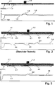
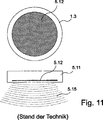
Zur besseren Erläuterung sei hier der Effekt des Verkippens bei einem herkömmlichen Sensor nach dem Stand der Technik dargestellt. 11 zeigt einen Sensor 1.3 mit einer Elektrode 5.12 zur Bestimmung der Kapazität mittels eines elektromagnetischen Feldes 5.15. Die dazugehörige Elektronik ist nicht dargestellt, die Funktionsweise wird als bekannt vorausgesetzt.For a better explanation, the effect of tilting is shown here in a conventional sensor according to the prior art. 11 shows a sensor 1.3 with an electrode 5.12 for determining the capacity by means of an electromagnetic field 5.15 , The associated electronics is not shown, the operation is assumed to be known.

Wird gemäß 1 der Sensor 1.3 aus einer vorgegebenen Position auf eine Wand 1.1 zu bewegt, verändert sich der Kapazitätswert C, dargestellt in der Messkurve 1.7 hin zu höheren Werten, bis die nächstmögliche Annäherung an die Wand 1.1 hergestellt ist. Eine ideale Bewegung entlang der Wand verändert den Messwert nicht, so lange kein Pfosten, Balken 1.2 oder ähnliches hinter der Wand liegt Zur Anzeige eines Balkens o. ä. kann dann z. B. ein Schwellwert 1.6 so oberhalb des Messwertes 1.7 gelegt werden, dass dieser bei einem Überfahren des Balkens 1.2 durch die entstehende Messwerterhöhung 1.8. überschritten wird.Is according to 1 the sensor 1.3 from a given position on a wall 1.1 moves to, the capacitance value C, shown in the trace changes 1.7 towards higher values, until the closest possible approach to the wall 1.1 is made. An ideal movement along the wall does not change the measured value, as long as no posts, beams 1.2 or similar is behind the wall To display a bar o. Ä. Can then z. B. a threshold 1.6 so above the reading 1.7 be put that this when crossing the beam 1.2 through the resulting increase in measured value 1.8 , is exceeded.

2 zeigt eine Messkurve, wie sie jedoch oft in der Realität vorkommt. Dargestellt ist die Wand 1.1 mit einer Putzbeschichtung 2.5, Unregelmäßigkeiten 2.1 und Inhomogenitäten 2.2. 2 shows a trace, as it often happens in reality. Shown is the wall 1.1 with a plaster coating 2.5 , Irregularities 2.1 and inhomogeneities 2.2 ,

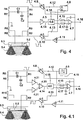
Die Unregelmäßigkeit kann z. B. eine etwas dickere Stelle im Putz sein oder ein Tapetenstoß. Trifft der Sensor 1.3 auf die Unregelmäßigkeit 2.1, hebt seine Sensorfläche zwangsweise leicht von der Wand ab. Dadurch verringert sich die Kapazität, die Messkurve 1.7 nimmt entsprechend ab (2, 2.3). Da dabei der Schwellwert 1.6 nicht überschritten wird, ist dies zunächst kein Problem.The irregularity can z. B. be a slightly thicker spot in the plaster or wallpaper splash. Meets the sensor 1.3 on the irregularity 2.1 , forcibly lifts its sensor surface slightly off the wall. This reduces the capacity, the trace 1.7 decreases accordingly ( 2 . 2.3 ). As the threshold value 1.6 is not exceeded, this is not a problem at first.

Kritisch wird es, wenn diese Unregelmäßigkeit im Bereich des zu ortenden Balkens 1.2 liegt. Dann kann es dazu kommen, das der Balken nicht erkannt wird (2, 2.6). Das heißt, die Kapazitätszunahme durch den hinter der Wand liegenden Balken wird durch das Verkippen des Sensors auf der Unregelmäßigkeit 2.1 überdeckt. In diesem Fall wird der Schwellwert 1.6 nicht überschritten und der Balken daher nicht geortet. Anders ist es bei einer Inhomogenität, z. B. einem Nagel. Dabei erhöht sich möglicherweise der Messwert 1.7 so weit, das der Schwellwert 1.6 überschritten und ein „Balken” vorgetäuscht wird.It becomes critical if this irregularity in the area of the beam to be located 1.2 lies. Then it can happen that the bar is not recognized ( 2 . 2.6 ). That is, the increase in capacity due to the behind-the-wall beam is due to the tilting of the sensor on the irregularity 2.1 covered. In this case, the threshold becomes 1.6 not exceeded and therefore the bar is not located. It is different in an inhomogeneity, z. B. a nail. This may increase the reading 1.7 so far, that's the threshold 1.6 exceeded and a "bar" is faked.

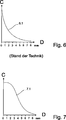
Die detektierte Kapazitätsabnahme des Sensors bei Verkippen bzw. leichten Abheben von der Wand nach dem Stand der Technik ist in 6 dargestellt. Es ist deutlich zu erkennen, dass im Stand der Technik in den ersten Millimetern einer Verkippung oder Entfernung des Sensors von der Oberfläche (6, D) die stärkste Änderung in der Kapazitatskurve 6.1 auftritt.The detected decrease in capacitance of the sensor during tilting or light lifting off the wall according to the prior art is in 6 shown. It can be clearly seen that in the prior art, in the first few millimeters, tilting or removal of the sensor from the surface (FIG. 6 , D) the strongest change in the capacity curve 6.1 occurs.

Aufgabe der ErfindungObject of the invention

Aufgabe der Erfindung ist die Schaffung eines kapazitiven Sensors, der vermindert und im besten Falle nicht auf Verkippung zur Oberfläche oder kleine Abstandsänderungen zur Oberfläche reagiert.The object of the invention is to provide a capacitive sensor which reduces and at best does not respond to tilting to the surface or small changes in the distance to the surface.

Aus der DE 10 2005 031 607 A1 ist eine Vorrichtung zur Wandlung der kapazitiven Signaländerung eines Differential-Kondensators, welcher in Beschleunigungssensoren verwendet wird, in ein digitales Signal bekannt. Hierzu wird ein Sigma-Delta-Modulator verwendet. Das Prinzip der Sigma-Delta-Modulation beruht auf einer groben Messung eines Signals mittels eines Quantisierers. Der dabei entstehende Messfehler wird integriert und über eine Gegenkopplung fortwährend kompensiert. Je nachdem, welche Art von Umwandlung vorgenommen werden soll, sind die einzelnen Blöcke des Sigma-Delta-Modulators digital oder analog ausgeführt. Der Differential-Kondensator ist in den Gegenkopplungspfad und die Referenzrückkopplungsstruktur integriert. Dadurch kann eine Kapazitätsänderung direkt von einem analogen Wert in ein digitales Signal gewandelt werden. Durch die Einbindung des Differential-Kondensators wird das Ausgangssignal des Wandlers in Form eines Binärstroms in erster Nährung nur abhängig von der Auslenkung der seismischen Masse des Differential-Kondensators. An die Elektroden des Differential-Kondensators werden verschiedene Referenzspannungen angelegt, die in einem bestimmten zeitlichen Muster mit bestimmter Amplitude wählbar sind. Durch verschieden gewählte Referenzspannungen können verschiedene Wertebereiche und Auflösungen des zu digitalisierenden Signals dargestellt werden. Durch eine geeignet gewählte Abfolge der Referenzspannungen wird ein Polaritätswechsel des Eingangssignals realisiert. Zudem kann für eine Selbsttestfunktion über die Folge der Referenzspannungen und eines geeigneten Taktschemas zum Aufschalten der Referenzspannungen auf die Elektroden eine Stellkraft auf die bewegliche Elektrode ausgeübt werden. Durch die Wahl der Referenzspannungen wird im zeitlichen Mittel eine Potentialgleichheit der Elektroden erreicht. Hierdurch wird eine elektrische Aufladung der seismischen Masse und die daraus entstehende Änderung des Ausgangssignals verhindert. Es erfolgt keine gegenläufige Regelung einer Sensorelektrode und einer die Sensorelektrode umgebenden weiteren Elektrode.From the DE 10 2005 031 607 A1 For example, a device for converting the capacitive signal change of a differential capacitor used in acceleration sensors into a digital signal is known. For this purpose, a sigma-delta modulator is used. The principle of sigma-delta modulation is based on a coarse measurement of a signal by means of a quantizer. The resulting measurement error is integrated and continuously compensated by a negative feedback. Depending on which type of conversion is to be made, the individual blocks of the sigma-delta modulator are digital or analog. The differential capacitor is integrated in the negative feedback path and the reference feedback structure. This allows a capacitance change to be converted directly from an analog value to a digital signal. Due to the integration of the differential capacitor, the output signal of the converter in the form of a binary current in the first approximation only depends on the deflection of the seismic mass of the differential capacitor. To the electrodes of the differential capacitor, different reference voltages are applied, which are selectable in a certain temporal pattern with a certain amplitude. Through different selected reference voltages different ranges of values and resolutions of the signal to be digitized can be displayed. By a suitably selected sequence of reference voltages, a polarity change of the input signal is realized. In addition, for a self-test function on the sequence of reference voltages and a suitable timing scheme for switching the reference voltages on the electrodes, a force acting on the movable electrode can be exercised. By selecting the reference voltages a potential equality of the electrodes is achieved in the time average. As a result, an electrical charge of the seismic mass and the resulting change in the output signal is prevented. There is no opposite control of a sensor electrode and a further electrode surrounding the sensor electrode.

Die DE 198 43 749 A1 zeigt als kapazitiver Näherungsschalter ein Verfahren und eine Schaltungsanordnung zur Auswertung kleiner Kapazitätsänderungen. Hierzu wird eine Brückenschaltung verwendet, in deren Brückenzweigen sich als Blindwiderstände je ein Kondensator befindet. Die beiden Brückenzweigspannungen werden getrennt nach dem jeweiligen Brückenzweig gleichgerichtet, wonach die Brückendiagonalspannung als sich entsprechend der Kapazitätsänderung der Kapazität ändernde Gleichspannung ausgewertet wird. Der Näherungsschalter besteht aus einer Mehrlagenplatine mit zwei elektrisch isolierenden Schichten, zwischen denen sich eine metallische Zwischenlage als erste Fläche eines Kondensators befindet. Auf einer der beiden Schichten ist eine flächige Auflage als Sonde aufgebracht, welche die zweite Fläche des Kondensators bildet. Eine Metallfläche ist relativ zur Sonde beweglich angeordnet und bildet mit dieser einen zweiten veränderbaren Kondensator. Durch diese Schaltungsanordnung wird eine erhöhte Störfestigkeit sowie eine erhöhte Temperaturstabilität erreicht. Hierzu wird die Schaltung mittels eines Drehkondensators derart abgeglichen, dass im Schaltzeitpunkt des Näherungsschalter die Differenzspannung gleich Null ist, da es dann ausreicht, lediglich das Vorzeichen auszuwerten.The DE 198 43 749 A1 shows as a capacitive proximity switch, a method and a circuit arrangement for the evaluation of small capacity changes. For this purpose, a bridge circuit is used, in whose bridge arms each reactance capacitor is a capacitor. The two bridge branch voltages are rectified separately after the respective bridge branch, after which the bridge diagonal voltage is evaluated as a DC voltage changing in accordance with the capacitance change of the capacitance. The proximity switch consists of a multi-layer board with two electrically insulating layers, between which a metallic intermediate layer is the first face of a capacitor. On one of the two layers, a flat support is applied as a probe, which forms the second surface of the capacitor. A metal surface is movably disposed relative to the probe and forms with it a second variable capacitor. By this circuit arrangement increased immunity to interference and increased temperature stability is achieved. For this purpose, the circuit is adjusted by means of a variable capacitor such that in the switching time of the proximity switch, the differential voltage is zero, since it is then sufficient to evaluate only the sign.

In der US 7,148,704 B2 ist eine kapazitive Erfassung der Position eines Objekts gezeigt, nämlich eines Fingers auf einem Touchpad. Der hierzu verwendete Sensor umfasst zwei Messkanäle, welche jeweils mit einer Elektrode verbunden sind. Die Kanäle werden synchron betrieben, wobei jeder Kanal eine nicht-lineare Antwort auf einen kapazitiven Einfluss des Fingers gibt. Diese jeweiligen Ausgangssignale werden linear zusammengefasst, um Positionssignale zu liefern, die sich linear mit der Position des Fingers verändern, weshalb der Sensor als ratiometrischer Sensor arbeitet.In the US 7,148,704 B2 For example, a capacitive detection of the position of an object, namely a finger on a touchpad, is shown. The sensor used for this purpose comprises two measuring channels, which are each connected to an electrode. The channels are operated synchronously, with each channel giving a non-linear response to a capacitive influence of the finger. These respective output signals are linearly combined to provide position signals that vary linearly with the position of the finger, which is why the sensor operates as a ratiometric sensor.

Die US 5,585,733 zeigt eine Vorrichtung und ein Verfahren zur Messung der Änderung der Kapazität eines kapazitiven Sensors. Hierzu sind Mittel zur Aufbringung eines konstanten elektrischen Stroms an einer Elektrode und Mittel zur Erzeugung einer ersten Reihe von Taktpulsen vorgesehen. Die Spannung des Kondensators wird mit einer Referenzspannung verglichen, wobei ein Signal erzeugt wird, wenn die Spannung des Kondensators die Referenzspannung überschreitet. Der kapazitive Sensor wird zur Messung der Änderung einer Dimension eines in den Dimensionen veränderlichen Gegenstands verwendet, wie beispielsweise einer Teleskopeinrichtung. Der Kondensator wird durch zwei elektrisch leitfähige Schichten gebildet, die dielektrische Hülsen eines Kolbens umschließen. Durch die Bewegung des Kolbens und damit der Hülsen wird die Kapazität des Kondensators verändert. Diese Änderung wird durch die Steuerung erfasst und ausgewertet, wodurch die Änderung der Position des Kolbens erfasst wird.The US 5,585,733 shows an apparatus and a method for measuring the change of Capacitance of a capacitive sensor. For this purpose, means for applying a constant electric current to an electrode and means for generating a first series of clock pulses are provided. The voltage of the capacitor is compared with a reference voltage, whereby a signal is generated when the voltage of the capacitor exceeds the reference voltage. The capacitive sensor is used to measure the change in dimension of a dimensionally variable article, such as a telescope device. The capacitor is formed by two electrically conductive layers which enclose dielectric sleeves of a piston. The movement of the piston and thus of the sleeves changes the capacitance of the capacitor. This change is detected and evaluated by the controller, which detects the change in the position of the piston.

Die DE 39 42 159 A1 zeigt eine Schaltungsanordnung zur Verarbeitung von Sensorsignalen, die mittels eines kapazitiven Sensors erfasst werden. Der Sensor umfasst eine durch die zu erfassenden physische Messgröße beeinflussbare Messkapazität und einen Referenzkondensator, der eine Referenzkapazität aufweist und einen von der Messkapazität und der Referenzkapazität abhängigen Messeffekt liefert. Erste Elektroden der Kondensatoren des Sensors liegen auf einem festen Potential, während zweite Elektroden zur Durchführung des Ladungstransports mit einem ersten Eingang eines Eingangsoperationsverstärkers verbunden sind, dessen zweiter Eingang auf einem Bezugspotential liegt. Die zur Bildung der transportierten Ladung erforderliche Umladung der Kondensatoren des Sensors erfolgt durch die Umschaltung des Bezugspotentials des Eingangsoperationsverstärkers. Somit liegen beide Eingänge des Operationsverstarkers im Wesentlichen virtuell auf dem gleichen Potential. Bedingt durch die Umschaltung des Bezugspotentials des Eingangsoperationsverstärkers wird daher auch das Potential der jeweils mit dem anderen Eingang verbundenen Kondensatorelektrode in gleicher Weise geändert. Somit werden die erforderlichen Spannungsänderungen an den mit der Signalleitung verbundenen Kondensatorelektroden vorgenommen, so dass nur diese aktiv sind. Die anderen Elektroden sind dann inaktiv und liegen auf einem beliebigen Potential, zum Beispiel auf dem Gehäusepotential des Sensors.The DE 39 42 159 A1 shows a circuit arrangement for processing sensor signals which are detected by means of a capacitive sensor. The sensor comprises a measuring capacitance which can be influenced by the physical measured variable to be detected and a reference capacitor which has a reference capacitance and supplies a measuring effect dependent on the measuring capacitance and the reference capacitance. First electrodes of the capacitors of the sensor are at a fixed potential, while second electrodes for carrying out the charge transport are connected to a first input of an input operational amplifier whose second input is at a reference potential. The transhipment of the capacitors of the sensor required to form the transported charge takes place by switching over the reference potential of the input operational amplifier. Thus, both inputs of the operational amplifier are essentially virtually at the same potential. Due to the switching of the reference potential of the input operational amplifier, therefore, the potential of each connected to the other input capacitor electrode is changed in the same way. Thus, the required voltage changes are made to the capacitor electrodes connected to the signal line, so that only these are active. The other electrodes are then inactive and are at an arbitrary potential, for example at the housing potential of the sensor.

Diese Aufgabe wird durch eine Vorrichtung mit den Merkmalen des Anspruches 1 und ein Verfahren mit den Merkmalen des Anspruches 5 gelöst.This object is achieved by a device having the features of claim 1 and a method having the features of claim 5.

Damit entsteht ein Sensor, der auch einen variablen Abstand zum flächigen Gegenstand beispielsweise einer Platte einnehmen kann. Gleichzeitig unterdrückt die umgebende Elektrode elektrische Einflüsse wie z. B. durch Feuchtigkeitsfilme auf der Sensoroberfläche. Am Ausführungsbeispiel eines „Balkenfinder” ergibt sich damit ein Sensor, der nicht auf Verkip-Zudem können vor allem bei einer Ausgestaltung nach den Ansprüchen 4 und 9 die Signale so stark verstärkt werden, dass eine deutlich höhere Reichweite z. B. hinter dem überstrichenen flächigen Gegenstand möglich wird oder sich die Objekte deutlicher abzeichnen. Findet dabei eine Messwertverrechnung aus mehreren Sensorelektroden zur Positionsdarstellung und/oder Dickendarstellung des Objekts statt, kann dieses auf einem Display dargestellt werden. Dies betrifft genauso die Darstellung einer Inhomogenität, z. B. einer Schraube als Einzelobjekt auf dem Display.This creates a sensor that can also take a variable distance to the flat object, for example, a plate. At the same time the surrounding electrode suppresses electrical influences such. B. by moisture films on the sensor surface. The embodiment of a "beam finder" thus results in a sensor that is not on Verkip-In addition, especially in an embodiment according to claims 4 and 9, the signals are amplified so strong that a significantly higher range z. B. behind the swept area object is possible or the objects are more apparent. If a measured value calculation takes place from a plurality of sensor electrodes for positional representation and / or thickness depiction of the object, this can be displayed on a display. This also applies to the representation of an inhomogeneity, z. B. a screw as a single object on the display.

Im Anwendungsfall der Touchpads und Annäherungssensoren kann ein kapazitiver Sensor in kleiner Ausführung realisiert werden, der die Position eines Fingers erfasst, bei der der Finger von einem festen Auflagepunkt aus nur gekippt, bzw. leicht aus der Position heraus „gerollt” wird. Die detektierte Position kann dann z. B. für eine Cursorsteuerung verwendet werden. Um eine fühlbare Haptik zu erreichen, wird zum Auslösen einer Funktion die Oberfläche gedrückt, z. B. um einen mechanische Microschalter zu betätigen. Ist aus konstruktiven Gründen der kapazitive Sensor nicht im beweglichen Teil integriert, wird trotz der Bewegung der Oberfläche während des Druckvorgangs die detektierte Position nicht „verrissen”.In the application of the touchpad and proximity sensors, a small-sized capacitive sensor can be realized which detects the position of a finger in which the finger is only tilted from a fixed support point, or slightly "rolled out" of position. The detected position can then z. B. be used for a cursor control. To achieve a tactile feel, the surface is pressed to trigger a function, z. B. to operate a mechanical microswitch. If, for structural reasons, the capacitive sensor is not integrated in the moving part, the detected position will not be "panned" despite the movement of the surface during the printing process.

Bei den Touchpads kann einer Mausfunktion gleich statt dem „Balken” auf dem Display eine Mausfunktion in Folge der Verrechnung der Messkurven mehrere Sensorteilbereiche dargestellt werden. Zudem ist auf Grund der hohen Empfindlichkeit des Systems auch eine Abstandserfassung eines sich annähernden Objekts wie eines Fingers in Richtung der Z-Achse möglich.In the case of touchpads, a mouse function can be displayed on the display instead of the "bar" on the display as a result of the billing of the measured curves of several sensor sections. In addition, due to the high sensitivity of the system, a distance detection of an approaching object such as a finger in the direction of the Z-axis is possible.

Vorzugsweise wird bei einer Ausführung nach den Ansprüchen 2 und 6 nicht nur die Anwesenheit sondern auch die Lage eines Balkens hinter der Wand dargestellt.Preferably, in an embodiment according to claims 2 and 6 not only the presence but also the position of a bar behind the wall is shown.

Weitere Vorteile ergeben sich aus den Unteransprüchen und der nachfolgenden Beschreibung.Further advantages emerge from the subclaims and the following description.

Kurzbeschreibung der FigurenBrief description of the figures

Im Folgenden wird die Erfindung an Hand von in den beigefügten Figuren dargestellten Ausführungsbeispielen erläutert. Es zeigen:In the following, the invention will be explained with reference to embodiments illustrated in the attached figures. Show it:

1 eine ideale Bewegung eines Sensors entlang eines flächigen Gegenstands sowie die dabei auftretende Änderung des Kapazitätswerts C, 1 an ideal movement of a sensor along a flat object as well as the occurring change in the capacitance value C,

2 eine Bewegung eines Sensors nach dem Stand der Technik entlang des flächigen Gegenstands gemäß 1 sowie die dabei auftretende Änderung des Kapazitätswerts C, 2 a movement of a sensor according to the prior art along the flat According to the article 1 as well as the occurring change of the capacitance value C,

3 eine Bewegung eines erfindungsgemäßen Sensors entlang des flächigen Gegenstends gemäß 1 sowie die dabei auftretende Änderung des Kapazitätswerts C, 3 a movement of a sensor according to the invention along the planar Gegenstends according to 1 as well as the occurring change of the capacitance value C,

4 ein Ausführungsbeispiel einer Sensorelektronik mit einer geschlossenen Regelung zur konstanten Erhaltung der Signalamplitude an der Sensorelektrode, 4 an embodiment of a sensor electronics with a closed control for the constant maintenance of the signal amplitude at the sensor electrode,

4.1 ein weiteres Ausführungsbeispiel einer Sensorelektronik mit Impedanzwandlern, 4.1 Another embodiment of a sensor electronics with impedance transformers,

5 einen erfindungsgemäßen Sensor, 5 a sensor according to the invention,

6, 7 die Abnahme der Kapazität bei zunehmendem Abstand von dem flächigen Gegenstand bei einem Sensor nach dem Stand der Technik und bei einem erfindungsgemäßen Sensor, 6 . 7 the decrease in the capacitance as the distance from the flat object increases in a sensor according to the prior art and in a sensor according to the invention,

8, 9 ein Ausführugsbeispiel eines weiteren erfindungsgemäßen Sensors mit Messwertverläufen verschiedener Kapazitätsverhältnisse und einer Anzeigeeinheit bei einem senkrecht und bei einem diagonal liegenden Balken oder Pfosten, 8th . 9 an exemplary embodiment of a further sensor according to the invention with measured value profiles of different capacitance ratios and a display unit in the case of a vertical and in a diagonally located beam or post,

10 ein Ausführungsbeispiel einer äußeren Beschaltung zur Realisierung der Erfindung mit einem IC, 10 An embodiment of an external circuit for implementing the invention with an IC,

11 einen Sensor mit einer Elektrode zur Bestimmung der Kapazität nach dem Stand der Technik. 11 a sensor with an electrode for determining the capacity of the prior art.

Beschreibung bevorzugter AusführungsbeispieleDescription of preferred embodiments

Bevor die Erfindung im Detail beschrieben wird, ist darauf hinzuweisen, dass sie nicht auf die jeweiligen Bauteile der Vorrichtung sowie die jeweiligen Verfahrensschritte beschränkt ist, da diese Bauteile und Verfahren variieren können. Die hier verwendeten Begriffe sind lediglich dafür bestimmt, besondere Ausführungsformen zu beschreiben und werden nicht einschränkend verwendet. Wenn zudem in der Beschreibung oder in den Ansprüchen die Einzahl oder unbestimmte Artikel verwendet werden, bezieht sich dies auch auf die Mehrzahl dieser Elemente, solange nicht der Gesamtzusammenhang eindeutig etwas Anderes deutlich macht.Before describing the invention in detail, it should be noted that it is not limited to the respective components of the device and the respective method steps, since these components and methods may vary. The terms used herein are intended only to describe particular embodiments and are not intended to be limiting. In addition, if singular or indefinite articles are used in the specification or claims, this also applies to the majority of these elements unless the overall context clearly makes otherwise clear.

Gegenüber dem Stand der Technik werden im erfindungsgemäßen Sensor 5.1 zur Detektion wenigstens zwei Elektroden eingesetzt 5 zeigt eine mögliche Anordnung. Eine ringförmige Elektrode 5.3 umgibt dabei die Sensorelektrode 5.2.Compared to the prior art are in the sensor according to the invention 5.1 used for detection at least two electrodes 5 shows a possible arrangement. An annular electrode 5.3 surrounds the sensor electrode 5.2 ,

Hierbei handelt es sich aber nicht um die im Stand der Technik so oft verwendete Schirmelektrode, die den inhomogenen Randbereich des elektrischen Felds eines kapazitiven Sensors von der Messelektrode abschirmt und so ein homogenes Feld bis an den Rand der Sensorfläche gewährleistet. Diese wird ja abhängig von dem Potential an der Messelektrode auf gleichem Potential mitgeführt. Dadurch wird die parasitäre Kapazität gegenüber einer umgebenden Massefläche eliminiert. Diese Maßnahme bevorzugt man, wenn nur kleine Kapazitätsänderungen an der Messelektrode detektiert werden sollen. Würde diese Messanordnung zur Balkenortung eingesetzt, ergibt sich beim Verkippen des Sensors in etwa die gleiche Kurve wie in 6 dargestellt.However, this is not the umbrella electrode used so often in the prior art, which shields the inhomogeneous edge region of the electric field of a capacitive sensor from the measuring electrode and thus ensures a homogeneous field up to the edge of the sensor surface. This is indeed carried depending on the potential at the measuring electrode at the same potential. This eliminates parasitic capacitance from a surrounding ground plane. This measure is preferred if only small changes in capacitance are to be detected at the measuring electrode. If this measuring arrangement were used for bar location, the tilting of the sensor results in approximately the same curve as in FIG 6 shown.

Nimmt im Stand der Technik das Potential an der Messelektrode zu oder ab, folgt die Schirmelektrode also diesem Potential. Als „Potential” kann eine Sinus- oder Recheckwechselspannung hochohmig auf die Messelektrode gegeben werden, eine Kapazitätserhöhung an der Messelektrode führt zu einer Verformung oder bei entsprechender Frequenz zu einer Abnahme der Wechselspannung.If the potential at the measuring electrode increases or decreases in the prior art, the shielding electrode thus follows this potential. As "potential" a sine or Recheckwechselspannung can be given high impedance to the measuring electrode, an increase in capacitance at the measuring electrode leads to a deformation or at a corresponding frequency to a decrease in the AC voltage.

„Hochohmige” Ankopplung heißt in der weiteren Darstellung, dass eine Kapazitätsänderung, z. B. durch einen Balken hinter der Wand, zu einer auswertbaren Änderung des Signals an der Messelektrode führt. „Niederohmige” Ankopplung heißt demnach, das z. B. die regelmäßig große Kapazitätsänderung durch Annähern des Sensors an die Wand nicht zu einer wesentlichen Beeinflussung des Kurvenverlaufs der Wechselspannung führt."High-impedance" coupling means in the further illustration that a change in capacity, for. B. by a bar behind the wall, leads to an evaluable change of the signal at the measuring electrode. "Low-impedance" coupling is accordingly, the z. B. the regularly large capacity change by approximating the sensor to the wall does not lead to a significant influence on the waveform of the AC voltage.

Eine „hochohmige” Ankoppelung der Messelektrode an die sendende Elektronik kann z. B. durch einen 470 KOhm Widerstand (bei einer Frequenz von z. B. 100 kHz) erfolgen. Dabei sind auch kleine Kapazitätsänderungen an der Messelektrode deutlich im Kurvenverlauf zu erkennen. Eine „niederohmige” Ankoppelung liegt z. B. bei Widerstandswerten um 100 Ohm vor, eine kleine Kapazitätsänderung an der angeschlossenen Elektrode führt dann zu einer kaum messbaren Signalbeeinflussung.A "high-impedance" coupling of the measuring electrode to the transmitting electronics can, for. B. by a 470 KOhm resistor (at a frequency of, for example, 100 kHz). At the same time, even small changes in capacity at the measuring electrode can be clearly seen in the course of the curve. A "low-impedance" coupling is z. For example, at resistance values of around 100 ohms, a small capacitance change at the connected electrode will lead to a hardly measurable signal interference.

Im erfindungsgemäßen Verfahren wird gemäß 5 die umgebende Elektrode 5.3 jedoch nicht auf dem Potential der Sensorelektrode 5.2 bzw. Messelektrode nachgeführt. Es wird vielmehr die Sensorelektrode ständig auf festgelegtem konstanten Potential gehalten. Bei Potentialabnahme durch eine Kapazitätserhöhung an der Sensorelektrode 5.2 wird das Potential der umgebenden Elektrode 5.3 so nachgeregelt, bis an der Sensorelektrode 5.2 wieder das festgelegte konstante Potential erreicht wird. Der Wert der Nachregelung ist dann der Wert der Kapazitätsänderung an der Sensorelektrode.In the inventive method is according to 5 the surrounding electrode 5.3 but not at the potential of the sensor electrode 5.2 or measuring electrode tracked. Rather, the sensor electrode is kept constantly at a fixed constant potential. When the potential is reduced by an increase in capacitance at the sensor electrode 5.2 becomes the potential of the surrounding electrode 5.3 so readjusted, up to the sensor electrode 5.2 again the fixed constant potential is reached. The value of the readjustment is then the value of the capacitance change at the sensor electrode.

Im nachfolgenden Ausführungsbeispiel wird eine Rechteck-Wechselspannung mit einer Frequenz von 100 kHz angelegt. Bei entsprechend hochohmiger Ankopplung verändert sich die Amplitude an der Sensorelektrode 5.2 bei Veränderung der Kapazität. Eine Amplitudenänderung bei Annäherung an einer Wand beträgt dann z. B. 10%, ein zusätzlicher Balken 1.2 hinter der Wand verändert die Amplitude zusätzlich z. B. um 0.1%. Diese Werte entsprechen der Praxis bei einer Holzwand von 18 mm Stärke und einem Balken von 5 × 5 cm, können jedoch bei unterschiedlichem Wandaufbau und div. Objekten dahinter stark unterschiedlich ausfallen. In the following embodiment, a rectangular AC voltage with a frequency of 100 kHz is applied. With correspondingly high-impedance coupling, the amplitude at the sensor electrode changes 5.2 when changing the capacity. An amplitude change when approaching a wall is then z. B. 10%, an additional bar 1.2 behind the wall the amplitude changes in addition z. By 0.1%. These values correspond to the practice of a wooden wall of 18 mm thickness and a beam of 5 × 5 cm, but may vary greatly with different wall structure and div. Objects behind it.

Wenn im Folgenden von Signalamplituden an den Elektroden die Rede ist, bezieht sich dieser Ausdruck auf oben genannte Darstellung.In the following, when referring to signal amplitudes at the electrodes, this term refers to the above-mentioned representation.

4 zeigt ein Ausführungsbeispiel einer Sensorelektronik mit einer geschlossenen Regelung zur konstanten Erhaltung der Signalamplitude an der Sensorelektrode. Ein Taktgenerator 4.8 liefert ein erstes Taktsignal 4.13 mit einer Frequenz von z. B. 100 kHz an eine erste geregelte Spannungsquelle 4.10 und ein zweites invertiertes Taktsignal 4.12 an eine zweite geregelte Spannungsquelle 4.9. Die erste geregelte Spannungsquelle 4.10 speist den niederohmigen Spannungsteiler aus R6 und R8, an dessen Mittelpunkt die Elektrode 5.3 liegt. 4 shows an embodiment of a sensor electronics with a closed control for the constant maintenance of the signal amplitude at the sensor electrode. A clock generator 4.8 provides a first clock signal 4.13 with a frequency of z. B. 100 kHz to a first regulated voltage source 4.10 and a second inverted clock signal 4.12 to a second regulated voltage source 4.9 , The first regulated voltage source 4.10 feeds the low-impedance voltage divider R6 and R8, at the center of which the electrode 5.3 lies.

Parallel dazu speist die gleiche Spannungsquelle 4.10 den hochohmigen Spannungsteiler R2 und R3. Der Fußpunkt von R3 liegt am Eingang des Wechselspannungsverstärkers 4.5. Da das Eingangssignal dieses Verstärkers aufgrund der im Folgenden näher erläuterten Regelung ständig auf „0” gehalten wird, kann hier für den Spannungsteller R2/R3 von einem virtuellen Massepotential ausgegangen werden. Am Mittelpunkt des Spannungsteilers R2 und R3 ist die Sensorelektrode 5.2 angeschlossen.In parallel, the same voltage source feeds 4.10 the high-impedance voltage divider R2 and R3. The base of R3 is at the input of the AC amplifier 4.5 , Since the input signal of this amplifier is constantly kept at "0" due to the control explained in more detail below, a virtual ground potential can be assumed here for the voltage regulator R2 / R3. At the midpoint of the voltage divider R2 and R3 is the sensor electrode 5.2 connected.

Das Verhältnis von R2 zu R3 entspricht vorzugsweise dem Verhältnis von R6 zu R8. In der Praxis z. B. je 100 Ohm für R6 und R8 und je 470 KOhm für R2 und R3.The ratio of R2 to R3 preferably corresponds to the ratio of R6 to R8. In practice z. For each 100 ohms for R6 and R8 and 470 KOhms for each of R2 and R3.

Analog zu dieser Anordnung speist die zweite geregelte Spannungsquelle 4.9 den niederohmigen Spannungsteller R5 und R7 und den hochohmigen Spannungsteiler R1 und R4. Die Sensorelektrode 5.2 bildet eine Kapazität gegenüber der Umwelt, z. B. gegenüber dem Gehäuse des Sensors. Die Kapazität des Kondensators C2 wird in etwa so groß wie diese Kapazität gewählt. Auch besteht zwischen der Sensorelektrode 5.2 und der umgebenden Elektrode 5.3 eine Kapazität. Die Kapazität des Kondensators C1 wird in etwa so groß wie diese Kapazität gewählt. C2 bildet somit die feststehende Referenzkapazität für die Sensorelektrode 5.2. Die Werte von R5, R7, R1 und R4 entsprechen den Werten für R6, R8, R2 und R3. Dieser Schaltungsteil bildet damit insgesamt eine Referenzstrecke zur den Sensor 5.1, 8.1 umfassenden Sendestrecke aus.Analogously to this arrangement, the second regulated voltage source feeds 4.9 the low-impedance voltage regulator R5 and R7 and the high-impedance voltage divider R1 and R4. The sensor electrode 5.2 forms a capacity towards the environment, eg. B. relative to the housing of the sensor. The capacitance of the capacitor C2 is selected to be about as large as this capacitance. Also exists between the sensor electrode 5.2 and the surrounding electrode 5.3 a capacity. The capacitance of the capacitor C1 is selected to be about as large as this capacity. C2 thus forms the fixed reference capacitance for the sensor electrode 5.2 , The values of R5, R7, R1 and R4 correspond to the values for R6, R8, R2 and R3. This circuit part thus forms a total of a reference path to the sensor 5.1 . 8.1 comprehensive transmission line.

Die Messwertverrechnung aus mehreren Sensorelektroden bzw. Sensorteilbereichen SA, SB, SC, SD kann somit zur Positionsdarstellung und/oder Dickendarstellung des Objekts hinter einer Wand auf einem Display oder auch zur Darstellung einer Inhomogenität wie einer Schraube als Einzelobjekt auf dem Display genutzt werden. In den anderen Anwendungsbereichen der Erfindung ist auch eine Mausfunktion auf dem Display vorstellbar. Statt dem „Balken” wird dann eine Mausfunktion auf dem Display dargestellt, wobei die Verrechnung der Messkurven in gleicher Weise erfolgen kann.The measured value calculation from a plurality of sensor electrodes or sensor subareas SA, SB, SC, SD can thus be used to display the position and / or thickness of the object behind a wall on a display or to display an inhomogeneity such as a screw as a single object on the display. In the other areas of application of the invention, a mouse function on the display is also conceivable. Instead of the "bar" then a mouse function is displayed, whereby the billing of the curves can be done in the same way.

Bei gleicher Spannung an den Ausgängen der Spannungsquellen 4.10 und 4.9 hebt sich das Eingangssignal am Wechselspannungsverstärker 4.5 auf.With the same voltage at the outputs of the voltage sources 4.10 and 4.9 the input signal at the AC amplifier rises 4.5 on.

Da der Verstärker 4.5 am Eingang im ausgeregeltem Zustand der Schaltung lediglich Rauschen sieht, kann er sehr hoch verstärken, bzw. als hoch verstärkender Begrenzerverstärker ausgeführt werden. Das Ausgangssignal des Verstärkers 4.5 wird dem Synchrondemodulator 4.6 zugeführt. Dieser erhält sein zur Demodulation nötiges Taktsignal über 4.18 aus dem Taktgenerator 4.8. Im einfachsten Fall führt der Synchrondemodulator 4.6 das Ausgangssignal des Verstärkers 4.5 während des gesamten Abschnitts einer Taktphase synchron den entsprechenden Eingängen des integrierenden Komparators 4.7 zu. Es ist jedoch auch möglich, nur taktabschnittsweise zu demodulieren.Because the amplifier 4.5 At the input in the regulated state of the circuit sees only noise, he can amplify very high, or be designed as a high-gain limiter amplifier. The output signal of the amplifier 4.5 becomes the synchronous demodulator 4.6 fed. This receives its necessary for demodulation clock signal over 4.18 from the clock generator 4.8 , In the simplest case, the synchronous demodulator leads 4.6 the output signal of the amplifier 4.5 during the entire portion of a clock phase synchronously with the corresponding inputs of the integrating comparator 4.7 to. However, it is also possible to demodulate only in a clock-wise manner.

Bei gleicher Spannung des ersten Eingangssignals 4.15 und zweiten Eingangssignals 4.17 des integrierenden Komparators 4.7 entsteht somit kein taktsynchroner Signalanteil am Eingang des Wechselspannungsverstärkers 4.5.At the same voltage of the first input signal 4.15 and second input signal 4.17 of integrating comparator 4.7 Thus, no isochronous signal component arises at the input of the AC amplifier 4.5 ,

Die den beiden Taktsignalen 4.12 und 4.13 zuordenbaren Ausgangssignale des Synchrondemodulators 4.6 werden vom integrierenden Komparator 4.7 auf Amplitudenunterschiede untersucht. Der Komparator 4.7 kann als hochverstärkende Vergleicherschaltung ausgeführt sein. Jede noch so kleine Abweichung der Eingangsspannungen 4.15 und 4.17 führt zu einer entsprechenden Abweichung des Regelwertes 4.16 vom momentanen Wert. Auf Grund der hohen Empfindlichkeit des Systems, d. h. auf Grund der hohen Verstärkung ist auch eine Annäherungsfunktion an den Sensor in Richtung einer Z-Achse möglich. Die zugehörige Information kann aus der Amplitude der Messkurven entnommen werden. So ist z. B. bei einer Mausfunktion eine Fingerdetektioqn z. B. bis 50 mm möglich.The two clock signals 4.12 and 4.13 assignable output signals of the synchronous demodulator 4.6 be from the integrating comparator 4.7 examined for amplitude differences. The comparator 4.7 can be designed as a high-gain comparator circuit. Every little deviation of the input voltages 4.15 and 4.17 leads to a corresponding deviation of the control value 4.16 from the current value. Due to the high sensitivity of the system, ie due to the high gain and an approach function to the sensor in the direction of a Z-axis is possible. The associated information can be taken from the amplitude of the traces. So z. B. in a mouse function a Fingerdetektioqn z. B. to 50 mm possible.

Die geregelten Spannungsquellen 4.9 und 4.10 werden mittels Invertierstufe 4.11 gegeneinander mit dem Regelwert 4.16 invertiert angesteuert. Steigt die Spannung einer der geregelten Spannungsquellen, so fällt sie in der anderen entsprechend ab. Für die Funktion des erfindungsgemäßen Sensors müssen jedoch nicht unbedingt die Spannungsquellen 4.9 bzw. 4.10 beide gegeneinander geregelt werden, es reicht auch die Regelung einer Spannungsquelle aus. Der Regelkreis wird über die Spannungsteiler, gebildet aus R1, R4 und R2, R3, geschlossen. Die Strecke über R1 und R4 bildet dementsprechend die Referenz zur Strecke über R3 und R2. The regulated voltage sources 4.9 and 4.10 are by means of Invertierstufe 4.11 against each other with the control value 4.16 controlled inverted. If the voltage of one of the regulated voltage sources rises, it drops accordingly in the other one. However, the voltage sources do not necessarily have to be necessary for the function of the sensor according to the invention 4.9 respectively. 4.10 Both are controlled against each other, it is also sufficient to control a voltage source. The control loop is closed via the voltage divider formed by R1, R4 and R2, R3. The route via R1 and R4 accordingly forms the reference to the route via R3 and R2.

Ohne den Einfluss eines flächigen Gegenstands der die Kapazität des Sensors verändert, z. B. der Wand, stellt sich daher ein Gleichgewicht der Spannungen am Ausgang der geregelten Spannungsquellen 4.9 und 4.10 in der Art ein, so das am Eingang des Verstärkers 4.5 keine taktsynchronen Anteile entstehen, das heißt, dass lediglich ein Rauschsignal am Eingang des Verstärkers 4.5 anliegt. Der Regelausgang 4.16 wird somit einen bestimmten elektrischen Wert einnehmen, der einem bestimmten, konstruktiv bedingten Kapazitätswert der Sensorelektrode 5.2 entspricht.Without the influence of a flat object of the capacity of the sensor changes, for. As the wall, therefore, a balance of voltages at the output of the regulated voltage sources 4.9 and 4.10 in the way, so at the input of the amplifier 4.5 no isochronous shares arise, that is, that only a noise signal at the input of the amplifier 4.5 is applied. The control output 4.16 Thus, it will assume a certain electrical value, which corresponds to a specific constructive capacitance value of the sensor electrode 5.2 equivalent.

Wenn nun z. B. der Sensor auf die Wand aufgesetzt wird, ändert sich die Kapazität der beiden Elektroden 5.2 und 5.3. Vorzugsweise ist dabei die aktiv auf die Oberfläche eines Objektes einwirkende Fläche der umgebenden Elektrode 5.3 etwa gleich groß der Fläche der Sensorelektrode 5.2. Die Kapazitätsänderung an der umgebenden Elektrode 5.3 wirkt sich so gut wie nicht auf den Regelkreis aus. Anders sieht es bei der Sensorelektrode 5.2 aus. Die Spannung wird aufgrund der Hochohmigkeit von R2, R3 abnehmen wollen. In diesem Fall entsteht am Eingang des Verstärkers 4.5 ein taktsynchroner Signalanteil, der sofort wieder zu „0” ausgeregelt wird. Dazu verändert sich der Regelwert 4.16 entsprechend.If now z. B. the sensor is placed on the wall, the capacitance of the two electrodes changes 5.2 and 5.3 , In this case, the surface of the surrounding electrode which actively acts on the surface of an object is preferably 5.3 about the same size of the surface of the sensor electrode 5.2 , The capacitance change at the surrounding electrode 5.3 has virtually no effect on the control loop. The situation is different with the sensor electrode 5.2 out. The voltage will decrease due to the high resistance of R2, R3. In this case arises at the input of the amplifier 4.5 an isochronous signal component, which is immediately corrected back to "0". This changes the control value 4.16 corresponding.

Die Spannung an der Sensorelektrode 5.2 wird somit immer gleich der Spannung an C2 gehalten. Eine Vergrößerung der Kapazität an der Sensorelektrode bewirkt somit keine Änderung des Spannungswertes an der Sensorelektrode, sondern führt zu einer Erhöhung der Spannung und somit des elektrischen Feldes 5.4 der umgebenden Elektrode 5.3.The voltage at the sensor electrode 5.2 is therefore always kept equal to the voltage at C2. An increase in the capacitance at the sensor electrode thus causes no change in the voltage value at the sensor electrode, but leads to an increase in the voltage and thus the electric field 5.4 the surrounding electrode 5.3 ,

Der dadurch entstehende Vorteil ist in 7 dargestellt.The resulting advantage is in 7 shown.

Zum Vergleich zeigt 6 die Kapazitätskurve 6.1 eines Sensors nach dem Stand der Technik. Bei Verkippen oder leichten Entfernen von der Wand entsteht sofort eine starke Kapazitätsänderung. Wird ein solcher Sensor über eine Wand mit Unregelmäßigkeiten geführt, entsteht der anfänglich in 2 beschriebene Fehler.For comparison shows 6 the capacity curve 6.1 a sensor according to the prior art. When tilted or easily removed from the wall, there is an immediate change in capacity. If such a sensor is routed over a wall with irregularities, the initial results in 2 described error.

7 zeigt dagegen die Kapazitätsänderung, wie sie bei gleichem Verkippen oder leichten Entfernen des Sensors von der Wand nach der erfindungsgemäßen Methode entsteht. Abstandsänderungen im Nahbereich der Wand führen zu fast keiner Veränderung der Kapazität und somit auch des Regelwertes. Kapazitätsänderungen in weiter vom Sensor entfernten Bereichen werden jedoch einwandfrei detektiert. 7 on the other hand shows the capacitance change, as it arises with the same tilting or easy removal of the sensor from the wall according to the method of the invention. Changes in distance in the vicinity of the wall lead to almost no change in the capacity and thus also in the control value. Capacitance changes in areas further away from the sensor are however detected correctly.

Wird, wie in 3 gezeigt, ein solcher Sensor über die Wand 1.1 geführt, so haben Unregelmäßigkeiten 2.1 sowie Inhomogenitäten 2.2 keinen Einfluss auf den Kapazitätswert C und somit auf den Regelwert 4.16. Die Ortung des hinter der Wand liegenden Balkens 1.2 erfolgt einwandfrei (3, 3.2).Will, as in 3 shown such a sensor over the wall 1.1 run, so have irregularities 2.1 as well as inhomogeneities 2.2 no influence on the capacitance value C and thus on the control value 4.16 , The location of the behind the wall beam 1.2 takes place flawlessly ( 3 . 3.2 ).

Messungen in der Praxis haben ergeben, des bei einem erfindungsgemäßen Sensor mit einer Fläche von 40 mm Durchmesser auf einer 18 mm starken Spanplatte eine Verkippung von 4–5 mm oder ein Abheben von 2 mm keinen wesentlichen Einfluss auf des Messergebnis hat. Dabei war es gleich, ob sich ein Balken hinter der Spanplatte befand oder nicht.Measurements in practice have shown that in a sensor according to the invention with an area of 40 mm diameter on a 18 mm chipboard has a tilt of 4-5 mm or a lift of 2 mm has no significant impact on the measurement. It did not matter if a beam was behind the chipboard or not.

Im Ausführungsbeispiel der 4 dienen die hochohmigen Widerstände R3 und R4 zur hochohmigen Abnahme des Spannungssignals an der Sensorelektrode 5.2. Werden ihre Werte gleich groß den Werten von R1 bzw. R2 gewählt, reduziert sich das zu detektierende Signal entsprechend.In the embodiment of 4 serve the high-impedance resistors R3 and R4 for high-impedance decrease of the voltage signal at the sensor electrode 5.2 , If their values are chosen equal to the values of R1 or R2, the signal to be detected is correspondingly reduced.

Zur Erhöhung der Empfindlichkeit des Sensors kann gemäß 4.1 das Signal der Sensorelektrode 5.2 bzw. des Kondensators C2 direkt über entsprechende Impedanzwandler 4.21 abgenommen und mit einem nachfolgenden Differenzverstärker 4.23 weiterverarbeitet werden. In diesem Fall sind die Signale der Spannungsquellen 4.9 und 4.10 im Gleichtakt. Die Widerstände R9 und R10 werden dann vorzugsweise gleich groß dem Eingangswiderstand der Eingangsimpedanz der impedanzwandler 4.21 gewählt oder können bei entsprechend hochohmigen Eingangsimpedanzen von 4.21 entfallen. Die Sendetakte 4.12 und 4.13 weisen dabei keine Phasenverschiebung auf.To increase the sensitivity of the sensor can according to 4.1 the signal of the sensor electrode 5.2 or the capacitor C2 directly via corresponding impedance converter 4.21 removed and with a subsequent differential amplifier 4.23 be further processed. In this case the signals are the voltage sources 4.9 and 4.10 in common mode. The resistors R9 and R10 are then preferably equal to the input resistance of the input impedance of the impedance converter 4.21 are selected or can be used with correspondingly high-impedance input impedances of 4.21 omitted. The transmission clock 4.12 and 4.13 have no phase shift.

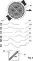
Eine weitere Ausführung eines erfindungsgemäßen Sensors 8.1 zeigt 8.Another embodiment of a sensor according to the invention 8.1 shows 8th ,

Die Sensorfläche 5.2 wurde in vier Sensorteilbereiche, also SA, SB, SC und SD aufgeteilt. Jeder Sensorteilbereich wird entsprechend 5 jeweils von dem entsprechenden umgebenden Elektrodenteilbereich 8.11 umfasst Ergänzend oder alternativ können auch die Sensorteilbereiche ihrerseits jeweils vollständig oder abschnittsweise von jeweils einer entsprechenden Elektrode umgeben sein. Eine Messung kann nun in der Weise erfolgen, dass jeweils ein Elektrodenteilbereich gegen die Referenzkapazität C2 gemessen wird. Z. B. SD gegen C2 usw. Zusätzlich kann auch jeder der Sensorteilbereiche gegenüber einem anderen Teilbereich gemessen werden, z. B. zur Entscheidung, ob es sich um einen länglichen Balken oder ein kleines Einzelobjekt hinter dem Sensor handelt. Im Ausführungsbeispiel in 8 werden die Messverläufe des Sensorteilbereichs SD gegen SB und SA gegen SC dargestellt.The sensor surface 5.2 was divided into four sensor subareas, ie SA, SB, SC and SD. Each sensor subarea will be corresponding 5 each from the corresponding surrounding electrode portion 8.11 In addition or as an alternative, the sensor subareas may also be in each case completely or partially in each case be surrounded by a corresponding electrode. A measurement can now take place in such a way that in each case one electrode subarea is measured against the reference capacitance C2. For example, SD against C2, etc. In addition, each of the sensor portions may be measured against another portion, for. To decide whether it is an elongated beam or a small single object behind the sensor. In the embodiment in 8th the measurement curves of the sensor section SD against SB and SA are shown against SC.

In 8 wird unter dem Sensor 8.1 ein Balken 8.2 von links nach rechts durchgeführt. Die Messungen der Sensorteilbereiche SA bis SD gegenüber der Referenzkapazität C2 ergeben die Messwertverläufe 8.3, 8.4, 8.5 und 8.6. Schon alleine aus diesen Messwertverläufen läst sich die Lage des Balkens berechnen und auf einem Display 8.9 als Balken 8.10 darstellen.In 8th will be under the sensor 8.1 a bar 8.2 performed from left to right. The measurements of the sensor subareas SA to SD relative to the reference capacitance C2 yield the measured value profiles 8.3 . 8.4 . 8.5 and 8.6 , Already from these measurements, the position of the bar can be calculated and displayed 8.9 as a bar 8.10 represent.

Zusätzliche Informationen liefert das Verhältnis der Kapazitäten der Sensorteilbereiche zueinander. Im Ausführungsbeispiel wird im Messwertverlauf 8.7 das Kapazitätsverhältnis des Sensorteilbereiches SD gegen den Sensorteilbereich SB und im Messwertverlauf 8.8 das Kapazitätsverhältnis des Sensorteilbereiches SA gegen den Sensorteilbereich SC dargestellt. Der Messwertverlauf 8,8 enthält z. B. keine Information, da der Balken bei seiner Bewegung die Sensorteilbereiche SA und SC gleich beeinflusst. So kann die genaue Lage des Balkens errechnet und entsprechend im Display dargestellt werden. Aus der Größe der Messwertänderungen im Messwertverlauf kann zusätzlich auf die Breite des Balkens geschlossen und dies entsprechend im Display dargestellt werden.Additional information provides the ratio of the capacities of the sensor sections to each other. In the exemplary embodiment, in the measured value course 8.7 the capacitance ratio of the sensor portion SD against the sensor portion SB and the measured value course 8.8 the capacity ratio of the sensor portion SA against the sensor portion SC shown. The measured value course 8th . 8th contains z. B. no information, since the beam in its movement affects the sensor portions SA and SC equal. Thus, the exact position of the bar can be calculated and displayed accordingly. From the size of the measured value changes in the measured value course can be additionally closed on the width of the bar and this is shown accordingly in the display.

9. zeigt die Messwertverläufe 9.3 bis 9.8 und die dazu entsprechende diagonale Darstellung des Balkens 9.1 auf dem Display 8.9 bei diagonaler Bewegung hinter dem Sensor 8.1. 9 , shows the measured value curves 9.3 to 9.8 and the corresponding diagonal representation of the bar 9.1 on the display 8.9 in diagonal movement behind the sensor 8.1 ,

Eine Möglichkeit für die Ausführung einer Elektronik 10.8 für die oben beschriebene Erfindung bietet der IC 909.05 der Fa. Elmos. Die prinzipielle äußere Beschattung zur Realisierung der Erfindung zeigt 10. Der IC beinhaltet fünf frei konfigurierbare geregelte Stromquellen 10.1 bis 10.5, (entsprechend den geregelten Spannungsquellen 4.9, 4.10) einen Eingang 10.6, die digitale Ausführung der in der Erfindung beschriebene Signalverarbeitung, eine interne Datenverarbeitungsmöglichkeit und einen entsprechenden Datentransfer 10.7.A possibility for the execution of an electronics 10.8 For the invention described above, the IC 909.05 from Elmos. The principal external shading for realizing the invention shows 10 , The IC contains five freely configurable regulated current sources 10.1 to 10.5 , (according to the regulated voltage sources 4.9 . 4.10 ) an entrance 10.6 , the digital implementation of the signal processing described in the invention, an internal data processing facility and a corresponding data transfer 10.7 ,

In 10 wird am Beispiel der Beschaltung der geregelten Stromquelle 10.1 dargestellt, wie die in der oben beschriebenen Erfindung eingesetzten Widerstände für die eine Sensorelektrode bzw. umgebende Elektrode beschaltet werden können, ebenso die Beschaltung für eine Referenzkapazität C2.In 10 is the example of the wiring of the regulated power source 10.1 illustrated how the resistors used in the invention described above for the one sensor electrode or the surrounding electrode can be connected, as well as the wiring for a reference capacitance C2.

BezugszeichenlisteLIST OF REFERENCE NUMBERS

1.11.1
Wandwall
1.21.2
Balkenbar
1.31.3
Sensor (Stand der Technik)Sensor (prior art)
1.41.4
Messwertreading
1.61.6
Schwellwertthreshold
1.71.7
Abnahme der MesskurveDecrease of the measuring curve
1.81.8
MesswerterhöhungMeasured value increase
1.91.9
Ruhezustand des RegelwertesHibernation of the control value
2.12.1
Unregelmäßigkeitirregularity
2,22.2
Inhomogenitätinhomogeneity
2.32.3
Messwert bei Verkappen ohne BalkenMeasured value for capping without bars
2.52.5
Putzbeschichtungplaster coating
2.62.6
Messwert bei Verkippen mit BalkenMeasured value for tilting with bars
1.81.8
MesswerterhöhungMeasured value increase
4.54.5
WechselspannungsverstäkerWechselspannungsverstäker
4.64.6
Synchrondemodulatorsynchronous
4.74.7
integrierender Komparatorintegrating comparator
4.84.8
Taktgeneratorclock generator
4.94.9
zweite geregelte Spannungsquellesecond regulated voltage source
4.104.10
erste geregelte Spannungsquellefirst regulated voltage source
4.114.11
Invertierstufeinverting
4.124.12
zweites, invertiertes Taktsignalsecond, inverted clock signal
4.134.13
erstes Taktsignalfirst clock signal
4.154.15
erstes Eingangssignal, Eingangsspannung des Komparatorfirst input signal, input voltage of the comparator
4.164.16
Regelwertcontrol value
4.174.17
zweites Eingangssignal, Eingangsspannung des Komparatorsecond input signal, input voltage of the comparator
4.184.18
Demodulator-TaktsignalDemodulator clock signal
4.214.21
Impedanzwandlerimpedance transformer
4.234.23
Differenzverstärkerdifferential amplifier
5.15.1
Erfindungsgemäßer SensorInventive sensor
5.115.11
Sensor mit einer ElektrodeSensor with an electrode
5.125.12
Sensorelektrode im Stand der TechnikSensor electrode in the prior art
5.155.15
Elektromagnetisches FeldElectromagnetic field
5.25.2
Sensorelektrodesensor electrode
5.35.3
Umgebende ElektrodeSurrounding electrode
5.45.4
Elektrisches Feld der umgebenden ElektrodeElectric field of surrounding electrode
6.16.1
Kapazitätskurve (Stand der Technik)Capacity curve (prior art)
8.18.1
weitere Ausführung des erfindungsgemäßen Sensorsfurther embodiment of the sensor according to the invention
8.28.2
Balkenbar
8.3–8.88.3-8.8
MesswertverlaufReading History
8.98.9
Displaydisplay
8.108.10
vertikale Balkendarstellungvertical bar graph
8.118.11
umgebende Elektrodesurrounding electrode
9.19.1
diagonale Balkendarstellungdiagonal bar graph
9.3–9.89.3-9.8
MesswertverlaufReading History
10.1–10.510.1-10.5
erste bis fünfte geregelte Stromquellefirst to fifth regulated current source
10.610.6
Eingangentrance
10.810.8
Elektronikelectronics
DD
Distanzdistance
C2C2
Referenzkapazitätreference capacity
SASA
Sensorteilbereich ASensor section A
SBSB
Sensorteilbereich BSensor section B
SCSC
Sensorteilbereich CSensor section C
SDSD
Sensorteilbereich DSensor section D

Claims (10)

Vorrichtung zur kapazitiven Erfassung eines, vorzugsweise hinter einem für eine elektromagnetische Strahlung durchlässigen flächigen Gegenstand oder einer Wand (1.1) angeordneten, Objekts wie eines Pfosten (1.2), einer Leitung oder eines Fingers mit – einem Sensor (5.1, 8.1), der Sensorelektroden zur Detektion des Objekts, vorzugsweise zur Detektion von Relativbewegungen zwischen Sensor und flächigem Gegenstand oder Finger aufweist, – einer Steuerschaltung zur Ansteuerung der Sensorelektroden und zur Auswertung der Ausgangssignale des Sensors, dadurch gekennzeichnet, dass der Sensor wenigstens eine Sensorelektrode (5.2; SA, SB, SC, SD) aufweist, die von wenigstens einer weiteren Elektrode (5.3; 8.11) umgeben ist, wobei die umgebende wertere Elektrode (5.3; 8.11) über die Steuerschaltung so mit der Sensorelektrode verbunden ist, dass bei einer Änderung des Potentials der Sensorelektrode die umgebende weitere Elektrode in ihrem Potential so zur Sensorelektrode gegenläufig geregelt wird, dass die Sensorelektrode auf einem vorbestimmten oder vorbestimmbaren Potential bleibt.Device for the capacitive detection of a, preferably behind an electromagnetic radiation transmissive sheet or a wall ( 1.1 ), objects such as a post ( 1.2 ), a wire or a finger with - a sensor ( 5.1 . 8.1 ), the sensor electrodes for detecting the object, preferably for detecting relative movements between the sensor and flat object or finger, - a control circuit for controlling the sensor electrodes and for evaluating the output signals of the sensor, characterized in that the sensor at least one sensor electrode ( 5.2 ; SA, SB, SC, SD) provided by at least one further electrode ( 5.3 ; 8.11 ), wherein the surrounding further electrode ( 5.3 ; 8.11 ) is connected via the control circuit to the sensor electrode so that when changing the potential of the sensor electrode, the surrounding further electrode is controlled in opposite directions in its potential to the sensor electrode, that the sensor electrode remains at a predetermined or predeterminable potential. Vorrichtung nach Anspruch 1, dadurch gekennzeichnet, dass die Sensorelektrode mehrere Sensorteilbereiche (SA, SB, SC, SD) aufweist, die insgesamt oder jeweils von der wenigstens einen umgebenden Elektrode (8.11) umgeben sind, und dass eine Auswerteeinheit vorgesehen ist, die die Kapazitätsverhältnisse der Sensorteilbereiche und/oder der umgebenden Elektrode zueinander oder zu einer Referenzkapazität (C2) zur Bestimmung der Lage und/oder Dicke des Objekts oder von Inhomogenitäten wie z. B. einer Schraube auswertet.Device according to Claim 1, characterized in that the sensor electrode has a plurality of sensor subregions (SA, SB, SC, SD) which are in total or in each case of the at least one surrounding electrode ( 8.11 ), and that an evaluation unit is provided, the capacity ratios of the sensor portions and / or the surrounding electrode to each other or to a reference capacitance (C2) for determining the position and / or thickness of the object or of inhomogeneities such. B. evaluates a screw. Vorrichtung nach Anspruch 1 oder 2, dadurch gekennzeichnet, dass die aktiv auf die Oberfläche des Objektes einwirkende Fläche der umgebenden Elektrode (5.3) etwa gleich groß der Fläche der Sensorelektrode (5.2) ist.Device according to claim 1 or 2, characterized in that the surface of the surrounding electrode actively acting on the surface of the object ( 5.3 ) is approximately equal to the area of the sensor electrode ( 5.2 ). Vorrichtung nach einem der vorhergehenden Ansprüche, dadurch gekennzeichnet, dass die Steuerschaltung eine Taktsteuerung (4.8) aufweist, die ein Taktsignal an die umgebende Elektrode (5.3; 8.11) zur Regelung des Potentials der Sensorelektrode (5.2) leitet und ein invertiertes Taktsignal als elektrisches Signal einer Referenzkapazität (C1, C2) zuleitet, wobei das von der Sensorelektrode (5.2) empfangene Signal durch äußere Einflüsse beeinflusst und mit dem invertierten Taktsignal überlagert ein Eingangssignal bildet, und/oder dass ein Synchrondemodulator (4.6) zur taktweisen Zuordnung des Eingangssignals so vorgesehen ist, dass an den Eingängen eines Komparators (4.7) das taktweise zerlegte Signal zur Bildung eines Vergleichswerts als Regelwert (4.16) ansteht, und dass im Signalgang des Taktsignals und/oder des invertierten Taktsignals wenigstens ein Amplitudenregler (4.9, 4.10) vorgesehen ist, der zur Regelung der Amplitudenwerte der Taktsignale den Regelwert (4.16) so verwendet, dass die Amplituden des taktweise zerlegten Eingangssignals zueinander im Wesentlichen gleich groß sind, sodass das Eingangssignal an den Eingängen des Vergleichers im ausgeregelten Zustand keine taktsynchronen Anteile enthält.Device according to one of the preceding claims, characterized in that the control circuit has a clock control ( 4.8 ), which sends a clock signal to the surrounding electrode ( 5.3 ; 8.11 ) for controlling the potential of the sensor electrode ( 5.2 ) and an inverted clock signal as an electrical signal of a reference capacitance (C1, C2) fed, wherein the of the sensor electrode ( 5.2 ) is influenced by external influences and superimposed on the inverted clock signal forms an input signal, and / or that a synchronous demodulator ( 4.6 ) is provided for the cyclic assignment of the input signal such that at the inputs of a comparator ( 4.7 ) the cyclically decomposed signal to form a comparison value as a control value ( 4.16 ) is present, and that in the signal path of the clock signal and / or the inverted clock signal at least one amplitude controller ( 4.9 . 4.10 ) is provided, which regulates the amplitude values of the clock signals, the control value ( 4.16 ) is used so that the amplitudes of the cyclically decomposed input signal to each other are substantially equal to each other, so that the input signal at the inputs of the comparator in the controlled state contains no isochronous components. Verfahren zur kapazitiven Erfassung eines, vorzugsweise hinter einem für eine elektromagnetische Strahlung durchlässigen flächigen Gegenstand oder eher Wand (1.1) angeordneten, Objekts wie einem Pfosten (1.2), einer Leitung oder eines Fingers, wobei eine Relativbewegung zwischen einem mit Elektroden versehener Sensor (5.1; 8.1) und einem flächigen Gegenstand oder dem Objekt erfolgt und durch die Erfassung von Kapazitätsänderungen die Lage des Objekts bestimmt wird und wobei eine Steuerschaltung die Sensorelektroden des Sensors ansteuert und dessen Ausgangssignal auswertet, dadurch gekennzeichnet, dass bei einer Änderung des Potentials der wenigstens einen Sensorelektrode (5.2; SA, SB, SC, AD) wenigstens eine die Sensorelektrode umgebende weitere Elektrode (5.3; 8.11) in Ihrem Potential gegenläufig zur Sensorelektrode geregelt wird, sodass die Sensorelektrode auf einem vorbestimmten oder vorbestimmbaren Potential bleibt.Method for the capacitive detection of a, preferably behind a electromagnetic radiation transmitting sheet or rather wall ( 1.1 ), objects such as a post ( 1.2 ), a wire or a finger, wherein a relative movement between an electrode-provided sensor ( 5.1 ; 8.1 ) and a flat object or the object takes place and the position of the object is determined by the detection of capacitance changes and wherein a control circuit controls the sensor electrodes of the sensor and evaluates the output signal, characterized in that when the potential of the at least one sensor electrode ( 5.2 ; SA, SB, SC, AD) at least one further electrode surrounding the sensor electrode ( 5.3 ; 8.11 ) is regulated in its potential in opposite directions to the sensor electrode, so that the sensor electrode remains at a predetermined or predeterminable potential. Verfahren nach Anspruch 5, dadurch gekennzeichnet, dass die Kapazitätsverhältnisse mehrerer Sensorteilbereiche (SA, SB, SC, SD) des Sensors (8.1) und/oder wenigstens einer die Sensorteilbereiche insgesamt oder jeweils einzeln umgebenden Elektrode (8.11) zueinander oder zu einer Referenzkapazität (C2) zur Bestimmung der Lage und/oder Dicke des Objekts oder von Inhomogenitäten wie z. B. einer Schraube ausgewertet werden.Method according to Claim 5, characterized in that the capacitance ratios of a plurality of sensor subregions (SA, SB, SC, SD) of the sensor ( 8.1 ) and / or at least one electrode surrounding the sensor subregions as a whole or in each case individually ( 8.11 ) to each other or to a reference capacitance (C2) for determining the position and / or thickness of the object or of inhomogeneities such. B. a bolt can be evaluated. Verfahren nach Anspruch 5 oder 6, dadurch gekennzeichnet, dass eine hochohmige Abnahme des Signals des Sensor über eine aktive Schaltung, insbesondere über Impedanzwandler (4.21) erfolgt und dass nach der aktiven Schaltung eine Zusammenführung des Signals der Sensorelektrode (5,2; SA, SB, SC, SD) und eines Referenzsignals aus einer Referenzstrecke aktiv über einen Differenzverstärker (4.23) erfolgt.A method according to claim 5 or 6, characterized in that a high-impedance decrease of the signal of the sensor via an active circuit, in particular via impedance converter ( 4.21 ) and that after the active circuit, a combination of the signal of the sensor electrode ( 5 . 2 ; SA, SB, SC, SD) and a reference signal from a reference path active via a differential amplifier ( 4.23 ) he follows. Verfahren nach einem der Ansprüche 5 bis 7, dadurch gekennzeichnet, dass eine Taktsteuerung (4.8) ein Taktsignal an die umgebende Elektrode (5.3) zur Regelung des Potentials der Sensorelektrode leitet und ein invertiertes Taktsignal an wenigstens einer Referenzkapazität (C1, C2) leitet und mit dem von der Sensorelektrode (5.1, 81.1) empfangenen Signal überlagert. Method according to one of claims 5 to 7, characterized in that a clock control ( 4.8 ) a clock signal to the surrounding electrode ( 5.3 ) for controlling the potential of the sensor electrode and an inverted clock signal at at least one reference capacitance (C1, C2) conducts and with the of the sensor electrode ( 5.1 . 81.1 ) received signal superimposed. Verfahren nach Anspruch 8, dadurch gekennzeichnet, dass die Taktsteuerung (4.8) der umgebenden Elektrode (5.3) das Taktsignal zuleitet, das gleichphasig von der Sensorelektrode (5.2) empfangen wird, wobei das an der Sensorelektrode anliegende Signal durch äußere Einflüsse beeinflussbar ist und mit dem invertierten Taktsignal überlagert ein Eingangssignal bildet, und dass das Eingangssignal taktweise so zergliedert wird, dass an den Eingängen eines Komparators (4.7) das taktweise zerlegte Signal zur Bildung eines Vergleichswerts als Regelwert (4.16) ansteht, und dass im Signalgang des Taktsignals und/oder des invertierten Taktsignals wenigstens ein Amplitudenregler (4.9, 4.10) vorgesehen ist, der zur Regelung der Amplitudenwerte der Taktsignale den Regelwert (4.16) so verwendet, dass die Amplituden des taktweise zerlegten Eingangssignals zueinander im Wesentlichen gleich groß sind, sodass das Eingangssignal an den Eingängen des Komparators (4.7) keine taktsynchronen Anteile enthält.Method according to claim 8, characterized in that the clock control ( 4.8 ) of the surrounding electrode ( 5.3 ) supplies the clock signal that is in phase with the sensor electrode ( 5.2 ), wherein the signal applied to the sensor electrode is influenced by external influences and superposed with the inverted clock signal forms an input signal, and that the input signal is cyclically dissected so that at the inputs of a comparator ( 4.7 ) the cyclically decomposed signal to form a comparison value as a control value ( 4.16 ) is present, and that in the signal path of the clock signal and / or the inverted clock signal at least one amplitude controller ( 4.9 . 4.10 ) is provided, which regulates the amplitude values of the clock signals, the control value ( 4.16 ) is used so that the amplitudes of the cyclically decomposed input signal to each other are substantially equal to each other, so that the input signal at the inputs of the comparator ( 4.7 ) contains no isochronous shares. Verfahren nach einem der Ansprüche 5 bis 9, dadurch gekennzeichnet, dass die Steuerschaltung mit hoch verstärkenden Bauelementen (4.5, 4.7, 4.23) den Abstand eines Objekts zum Sensor der Amplitude der Messkurven entnimmt.Method according to one of claims 5 to 9, characterized in that the control circuit with high-gain components ( 4.5 . 4.7 . 4.23 ) takes the distance of an object to the sensor of the amplitude of the traces.
DE102009057439A 2009-10-27 2009-12-09 Device and method for error-free capacitive measured value acquisition Revoked DE102009057439B4 (en)

Priority Applications (7)

Application Number Priority Date Filing Date Title
DE102009057439A DE102009057439B4 (en) 2009-10-27 2009-12-09 Device and method for error-free capacitive measured value acquisition
CA2775638A CA2775638A1 (en) 2009-10-27 2010-10-25 Apparatus and method for capacitively recording measured values without errors
PCT/EP2010/006507 WO2011054459A1 (en) 2009-10-27 2010-10-25 Apparatus and method for capacitively recording measured values without errors
JP2012535668A JP5836960B2 (en) 2009-10-27 2010-10-25 Apparatus and method for error-free capacitance measurement detection
CN201080048964.3A CN102741711B (en) 2009-10-27 2010-10-25 Apparatus and method for capacitively recording measured values without errors
EP10776306.2A EP2494382B1 (en) 2009-10-27 2010-10-25 Apparatus and method for capacitively recording measured values without errors
US12/911,806 US9035662B2 (en) 2009-10-27 2010-10-26 Method and device for accurate capacitive measured value acquisition

Applications Claiming Priority (3)

Application Number Priority Date Filing Date Title
DE102009050894.5 2009-10-27
DE102009050894 2009-10-27
DE102009057439A DE102009057439B4 (en) 2009-10-27 2009-12-09 Device and method for error-free capacitive measured value acquisition

Publications (2)

Publication Number Publication Date
DE102009057439A1 DE102009057439A1 (en) 2011-05-05
DE102009057439B4 true DE102009057439B4 (en) 2012-09-27

Family

ID=43828927

Family Applications (1)

Application Number Title Priority Date Filing Date
DE102009057439A Revoked DE102009057439B4 (en) 2009-10-27 2009-12-09 Device and method for error-free capacitive measured value acquisition

Country Status (7)

Country Link
US (1) US9035662B2 (en)
EP (1) EP2494382B1 (en)
JP (1) JP5836960B2 (en)
CN (1) CN102741711B (en)
CA (1) CA2775638A1 (en)
DE (1) DE102009057439B4 (en)
WO (1) WO2011054459A1 (en)

Cited By (1)

* Cited by examiner, † Cited by third party
Publication number Priority date Publication date Assignee Title
DE102014216246A1 (en) * 2014-08-15 2016-02-18 Mayser Gmbh & Co. Kg Circuit and method for evaluating measuring signals and sensor system for the capacitive detection of obstacles

Families Citing this family (13)

* Cited by examiner, † Cited by third party
Publication number Priority date Publication date Assignee Title
DE102011079704A1 (en) * 2011-07-25 2013-01-31 Robert Bosch Gmbh detector
JP5846930B2 (en) * 2012-01-24 2016-01-20 株式会社ジャパンディスプレイ Touch panel, display device and electronic device
DE102012205097A1 (en) * 2012-03-29 2013-10-02 Robert Bosch Gmbh Capacitive locating device
JP2015122141A (en) * 2013-12-20 2015-07-02 アイシン精機株式会社 Electrostatic capacitance sensor electrode
DE102015202880A1 (en) * 2015-02-18 2016-08-18 Zircon Corp. Method and device for detecting an object hidden behind an object
US9888843B2 (en) * 2015-06-03 2018-02-13 Microsoft Technology Licensing, Llc Capacitive sensors for determining eye gaze direction
US10571423B2 (en) * 2016-06-24 2020-02-25 Stanley Black & Decker Inc. Systems and methods for locating a stud
US10908312B2 (en) 2016-06-24 2021-02-02 Stanley Black & Decker Inc. Systems and methods for locating a metal object
CN107478145B (en) * 2017-09-05 2019-05-21 湘潭大学 A kind of tip formula multi-pole capacitance sensor of welding gun pose detection
EP3608624B1 (en) * 2018-08-06 2022-06-29 Hexagon Technology Center GmbH Capacitive distance sensor
CN110031883B (en) * 2019-03-05 2022-06-07 中国辐射防护研究院 High ionizing radiation dose sensor based on wireless capacitance
JP2022037568A (en) * 2020-08-25 2022-03-09 マックス株式会社 Power tool
US11640009B2 (en) * 2021-08-26 2023-05-02 Peaceful Thriving Enterprise Co., Ltd. In-wall feature detection device of mutual capacitive technology

Citations (5)

* Cited by examiner, † Cited by third party
Publication number Priority date Publication date Assignee Title
DE3942159A1 (en) * 1989-12-20 1991-06-27 Endress Hauser Gmbh Co ARRANGEMENT FOR PROCESSING SENSOR SIGNALS
US5585733A (en) * 1992-09-10 1996-12-17 David Sarnoff Research Center Capacitive sensor and method of measuring changes in capacitance
DE19843749A1 (en) * 1998-08-03 2000-02-17 Pepperl & Fuchs Method and circuit arrangement for evaluating small changes in capacity
DE102005031607A1 (en) * 2004-07-17 2006-02-09 Robert Bosch Gmbh Sigma-delta-modulator e.g. for acceleration sensor, has differential capacitor forming component of signal supply structure and reference feedback structure
US7148704B2 (en) * 2002-10-31 2006-12-12 Harald Philipp Charge transfer capacitive position sensor

Family Cites Families (19)

* Cited by examiner, † Cited by third party
Publication number Priority date Publication date Assignee Title
US4099118A (en) * 1977-07-25 1978-07-04 Franklin Robert C Electronic wall stud sensor
US4879508A (en) * 1986-04-04 1989-11-07 Mitutoyo Corporation Capacitance-type measuring device for absolute measurement of positions
DE4001814A1 (en) * 1990-01-23 1991-07-25 Vdo Schindling EVALUATION FOR A CAPACITIVE SENSOR
US5352974A (en) 1992-08-14 1994-10-04 Zircon Corporation Stud sensor with digital averager and dual sensitivity
US5726581A (en) * 1996-03-08 1998-03-10 The United States Of America As Represented By The Administrator Of The National Aeronautics And Space Administration 3-D capaciflector
US5917314A (en) * 1996-08-08 1999-06-29 Zircon Corporation Electronic wall-stud sensor with three capacitive elements
JP3772027B2 (en) * 1998-07-21 2006-05-10 有限会社イーグル電子 Capacitance type detection device
JP4083888B2 (en) * 1998-08-25 2008-04-30 ジェイ・エス・ケー株式会社 Moisture detector
DE10131243C1 (en) * 2001-06-28 2002-11-07 Luer Luetkens Capacitive proximity switch e.g. for production line robot, uses difference signal between 2 screened sensor electrodes
US6894508B2 (en) * 2002-06-28 2005-05-17 Solar Wide Industrial Ltd. Apparatus and method for locating objects behind a wall lining
DE10239431A1 (en) * 2002-08-28 2004-03-04 Robert Bosch Gmbh Locating device and method for producing a locating device
DE10324579A1 (en) 2003-05-30 2004-12-16 Daimlerchrysler Ag operating device
DE102004007315A1 (en) * 2004-02-14 2005-08-25 Robert Bosch Gmbh Short-range radar unit for detecting objects in a medium, e.g. for detecting reinforcement bars or electrical wiring buried in a wall, has one or more additional sensors, e.g. inductive, capacitive, photometric or infrared
US7116091B2 (en) * 2004-03-04 2006-10-03 Zircon Corporation Ratiometric stud sensing
US6989662B2 (en) 2004-04-29 2006-01-24 Zircon Corporation Sensor auto-recalibration
US20090045822A1 (en) * 2007-08-13 2009-02-19 Windbond Electronics Corporation Capacitive detection systems, modules and methods
DE102007048402A1 (en) 2007-10-09 2009-04-16 Gerd Reime Control unit and method for triggering a function
US7982450B2 (en) * 2008-02-13 2011-07-19 Lanny S Smoot Device and method allowing the detection and display of objects located behind an obscuring surface
DE102008035627A1 (en) * 2008-07-31 2010-02-11 Gerd Reime Device for the capacitive measurement of changes

Patent Citations (5)

* Cited by examiner, † Cited by third party
Publication number Priority date Publication date Assignee Title
DE3942159A1 (en) * 1989-12-20 1991-06-27 Endress Hauser Gmbh Co ARRANGEMENT FOR PROCESSING SENSOR SIGNALS
US5585733A (en) * 1992-09-10 1996-12-17 David Sarnoff Research Center Capacitive sensor and method of measuring changes in capacitance
DE19843749A1 (en) * 1998-08-03 2000-02-17 Pepperl & Fuchs Method and circuit arrangement for evaluating small changes in capacity
US7148704B2 (en) * 2002-10-31 2006-12-12 Harald Philipp Charge transfer capacitive position sensor
DE102005031607A1 (en) * 2004-07-17 2006-02-09 Robert Bosch Gmbh Sigma-delta-modulator e.g. for acceleration sensor, has differential capacitor forming component of signal supply structure and reference feedback structure

Cited By (1)

* Cited by examiner, † Cited by third party
Publication number Priority date Publication date Assignee Title
DE102014216246A1 (en) * 2014-08-15 2016-02-18 Mayser Gmbh & Co. Kg Circuit and method for evaluating measuring signals and sensor system for the capacitive detection of obstacles

Also Published As

Publication number Publication date
JP2013508734A (en) 2013-03-07
CN102741711B (en) 2014-11-12
JP5836960B2 (en) 2015-12-24
US20110095771A1 (en) 2011-04-28
WO2011054459A1 (en) 2011-05-12
EP2494382A1 (en) 2012-09-05
EP2494382B1 (en) 2020-03-11
CA2775638A1 (en) 2011-05-12
DE102009057439A1 (en) 2011-05-05
US9035662B2 (en) 2015-05-19
CN102741711A (en) 2012-10-17

Similar Documents

Publication Publication Date Title
DE102009057439B4 (en) Device and method for error-free capacitive measured value acquisition
EP2567459B1 (en) Detection of a dielectric object
EP2147364B1 (en) Sensor apparatus and method for generating signals indicative of the position or change in position of limbs
DE202017105709U1 (en) Device for detecting user input
EP2364526B1 (en) Sensor device for generating signals that are indicative of the position or change of position of limbs
EP3166228A1 (en) Sensor module, sensor system and method for capacitive and spatially resolved detection of approaching and contact, use of the sensor module
WO2011131557A1 (en) Method for measuring the coordinates of workpieces on a coordinate-measuring device
DE102012019329A1 (en) Method and sensor unit for locating and / or detecting metallic or metal-containing objects and materials
WO2016087231A1 (en) Sensor system for a motor vehicle steering wheel, steering wheel comprising said type of sensor system and method for operating a sensor system of said type
EP4325183A2 (en) Sensor system for detecting a movement of an infrared light source
DE102011078369B4 (en) Capacitive sensor device and method for calibrating a capacitive sensor device
DE102008047434B4 (en) Method and circuit for detecting an approach to an electrode device
DE102009021804A1 (en) Metal detector has at least one transmission coil and at least one reception coil working in a pulse induction mode
DE102012205126A1 (en) Capacitive locating device
DE102013106704A1 (en) Device for non-contact detection and / or distance determination of at least one object relative to a measuring body and method therefor
DE102007028335B4 (en) Capacitive measuring system with auto-calibration
EP3824323B1 (en) Detector for detecting electrically conductive material
DE102010024658A1 (en) Touch-sensitive surface
DE102013224235A1 (en) Sensor system for capacitive distance measurement
EP2862277B1 (en) Beam detector with control circuit
AT504403B1 (en) METHOD AND DEVICE FOR MEASURING TWO PARTIAL CAPACITIES
DE102020110172A1 (en) Method for capacitive touch and actuation detection
EP4191116A1 (en) Safety device
DE102009055143A1 (en) Touch-sensitive button
DE102015015072A1 (en) Keyboard with touch elements

Legal Events

Date Code Title Description
OP8 Request for examination as to paragraph 44 patent law
R016 Response to examination communication
R018 Grant decision by examination section/examining division
R026 Opposition filed against patent

Effective date: 20121221

R006 Appeal filed
R008 Case pending at federal patent court
R010 Appeal proceedings settled by withdrawal of appeal(s) or in some other way
R037 Decision of examining division or of federal patent court revoking patent now final