The application be that March 20 calendar year 2001, application number are 01109868.6 the applying date, denomination of invention divides an application for the application for a patent for invention of " auxiliary equipment for respiration ".
Background technology
There have been several that method of humidified gases is provided to the patient who needs Breath supplementing in the prior art.These humidifiers of the prior art generally include a compressed air (or other mist) source, one and hold humidifying container and conduit that is used for humidified gases is flowed to patient or user that a water source and are used to make the heater of water vapor.
For example U.S. Patent No. 4,038, and 980 have described " flash " humidifier, and wherein water droplet drops on the hot piece heater in bottom, thereby produce the dampness that is used to breathe.This patent is mentioned " can adopt a kind of device, make it the sensing device of relative humidity is produced response, thereby the delivery rate of regulating water automatically ", yet they recommend the flow rate of water is manually controlled.Like this, this patent comprises a humidity sensor and to the control of flow rate, rather than the electrical heating amount is controlled.
U.S. Patent No. 5,092,326 have also described the application of humidity sensor in humidifier.A high frequency air exchange system has been described in this invention, and this system has used humidifier and humidity sensor of a heating, and wherein these assemblies all are connected with a center microprocessor.This disclosure of the Invention one be the equipment of supply to the mist humidification of airway, and a microprocessor is controlled the amount of moisture of supplying with mist.Although this patent disclosure a humidity sensor that is positioned at patient's airway place, the practical structures with adopted humidification apparatus is not described.
U.S. Patent No. 5,769,071 has described a kind of humidifier, and this humidifier comprises a hot Wet exchanger (HME), water supply, heating element heater and the humidity sensor to HME.This humidity sensor can be controlled humidity by the delivery rate or the temperature (passing through heating element heater) of water.In this patent, humidity sensor also is disposed in patient's airway place.
U.S. Patent No. 5,988,164 have described a kind of and the heating breathing catheter system that humidifier is used.This system has adopted a near relative humidity sensor (being positioned at the patient), is used for the heating heat that adds that breathing circuit provided is controlled, thereby makes gas have constant relative humidity.This heating breathing circuit can use electrical heating, or heats by the warm recirculation water in the conduit.The method that a kind of output valve according to relative humidity sensor is controlled electrical heating wire or hot-water line has also been described in this invention.
Humidifying container in above-mentioned U.S. Patent No. 4,038,980 and 5,769, the 071 described humidifier all be disposed in patient near.Its disadvantage is, increased near weight, heat and the complexity of the equipment the patient, and this is not only inconvenient, but also patient is not felt well.In the prior art of mentioning, have only U.S. Patent No. 5,988 in the above, 164 have described especially and have been placed on the humidifying container at a distance apart from patient.
Adopted in the prior art systems of the humidifying container far away and also existed some shortcomings apart from patient.It is conventionally believed that when gas leaves this prior art humidifier the water vapour in this gas reach capacity (100% relative humidity).Yet can guarantee that without any basis the gas that leaves this humidifier has reached the saturated of water vapour really.(for example, when the gas of import has been heated) in some cases, the relative humidity that leaves the gas of this humidifier will be significantly less than 100%.This is to reach an ideal Outlet Gas Temperature because this gas is usually controlled, and the temperature of this Outlet Gas Temperature and intake air is more or less the same in the case.
Another shortcoming in the prior art systems is the phenomenon of condensing may occur at the conduit (being heated sometimes) that is used for patient is connected with respiratory assistance apparatus.If temperature is along the skewness of this conduit and make the temperature at some position of this conduit be lower than the gas temperature at these positions, so just be easy to generate this phenomenon of condensing.
The 3rd shortcoming of this prior art systems is, when gas leaves humidifier with 100% relative humidity, this gas must be subjected to the heating of the conduit heater of certain form immediately, otherwise heat wherein will lose by catheter wall, this will cause condensing of moisture, and therefore cause the decline of absolute humidity amount contained in the gas.
The 4th shortcoming of prior art systems is to need a pick off very near apart from patient, and this will increase the weight and volume of the equipment at patient's airway place.
The 5th shortcoming of prior art systems is that the absolute humidity that flow rate discontinuous or that change will make humidifier produce is inhomogeneous.This is because the variation of flow rate is all rapider than any variation that can be applied in the control loop in this humidifier.With flow through almost not free being heated or humidification of gas of humidifier of higher flow rate, all will be too high and flow through the temperature and the absolute humidity of gas of humidifier with lower flow rate.Therefore, be difficult to guarantee that conduit in this prior art systems does not produce hydrogenesis when carrying the air mass of these high humility and the reduction of the absolute humidity that causes thus.
Summary of the invention
Therefore, an object of the present invention is to provide a kind of humidification system, this humidification system can overcome above-mentioned shortcoming by certain mode, perhaps can provide a useful selection for the public at least.
In first aspect, main points of the present invention are a kind of humidification apparatus that are used for air-flow is carried out humidification, and described air-flow is transferred to patient or needs other people of this gas, and this humidification apparatus comprises:
Humidifying container device, this humidifying container device have an import and outlet that allows the described humidifying container device of described airflow passes,
The container heater, this container heater is disposed near the described humidifying container, and be used for making the aqueous water vaporization of described humidifying container device, thereby provide water vapour to the described air-flow of the described humidifying container device of flowing through,
The gas delivery channels device, this device is connected with the described outlet of described humidifying container device, thereby with described air-flow carry to patient or need this gas other people and
Humidity sensing device, this device are used to the absolute humidity at place more at least in the runner of the described air-flow that passes described equipment is indicated.
In second aspect, main points of the present invention are a kind of humidification apparatus that are used for air-flow is carried out humidification, and described air-flow is transferred to patient or needs other people of this gas, and this humidification apparatus comprises:
Humidifying container device, this humidifying container device have an import and outlet that allows the described humidifying container device of described airflow passes,
The container heater, this container heater is disposed near the described humidifying container, this device comprises the aqueous water vaporization that is used for making described humidifying container device, thereby provide the wet heater of water vapour to the described air-flow of the described humidifying container device of flowing through, carry out direct-fired dried heater with the described air-flow that is used for the described humidifying container device of flowing through
The gas delivery channels device, this device is connected with the described outlet of described humidifying container device, thereby with described air-flow carry to patient or need this gas other people and
Control device, this control device are used for described wet heater of conducting and described dried heater, thereby obtain ideal absolute humidity.
In the third aspect, main points of the present invention are a kind of humidification apparatus that are used for air-flow is carried out humidification, and described air-flow is transferred to patient or needs other people of this gas, and this humidification apparatus comprises:
Humidifying container device, this humidifying container device have an import and outlet that allows the described humidifying container device of described airflow passes,
The container heater, this container heater is disposed near the described humidifying container, and be used for making the aqueous water vaporization of described humidifying container device, thereby provide water vapour to the described air-flow of the described humidifying container device of flowing through,
The gas delivery channels device, this device is connected with the described outlet of described humidifying container device, thereby with described air-flow carry to patient or need this gas other people and
Controlled conduit heater, this device are used to regulate described air-flow along the Temperature Distribution of described gas delivery channels device and/or the Temperature Distribution of described gas delivery channels device, thereby make it a basic symbols unification predetermined distribution.
In fourth aspect, main points of the present invention are a kind of humidification apparatus that are used for air-flow is carried out humidification, and described air-flow is transferred to patient or needs other people of this gas, and this humidification apparatus comprises:
Humidifying container device, this humidifying container device have an import and outlet that allows the described humidifying container device of described airflow passes,
The container heater, this container heater is disposed near the described humidifying container, is used for making the aqueous water vaporization of described humidifying container device, thereby to the described air-flow of the described humidifying container device of flowing through provide water vapour and
Container manifold device, this container manifold device comprises erecting device, and this erecting device in use accommodates a sensing device near the described outlet of described humidifying container device at least, described container manifold device is used to:
The described import of described humidifying container device is connected with a feed line device, and described feed line device in use with between the gas supply device has gas to communicate, so that make described air-flow have ideal pressure, and/or
The described outlet of described humidifying container device is connected with a gas delivery channels device, thereby carries described air-flow to patient or need other people of this gas.
Those of ordinary skill in the field involved in the present invention should be understood that and can carry out various structural modifications to the present invention, and can design a large amount of different embodiment or application example, yet this does not depart from the scope of the present invention.Open and explanation herein only is for the convenience on illustrating, and the present invention is not constituted the restriction of going up in all senses.
The specific embodiment
Fig. 1 has represented a typical respiratory humidification system, and this system comprises following three parts:
1) one with patient's humidifying container separated by a distance, this container is used to its gas of flowing through is heated, and this gas is reached capacity substantially;
2) induction system, this system comprise an elastic tube that humidified gases is delivered to gas outlet 5 from humidifying container 1; With
3) heated base, this heated base heats humidifying container 1, and measurement and control function are provided.
Will be flowed into container 1 from opening 4 by the gas of humidification, and leave induction system 2 at gas outlet 5 places.Flow to patient from exporting 5 effluent airs by a face shield or similar device (not shown).This system is controlled by the pick off that use is arranged in 7 and 8 places, and described pick off is generally temperature sensor.The dry gas at gas feed 4 places is flowed through by the surface of the hot water from container 16 and is heated and humidification, like this, when these gases leave container 1 at outlet 10 places, just can reach the saturated of water vapour substantially.Hot water 6 is heated by heating plate 9, and adds heat and be controlled, thereby makes gas reach a predetermined temperature at outlet 10 places.This temperature is measured by pick off 7.Therefore, humidifying container 1 is used to medical gas is heated and humidification, thereby this gas is reached capacity substantially in the exit of container 1, and reaches a predetermined temperature.
Gas delivery system 2 (be also referred to as delivery conduit or breathe pipeline) comprises an elastic catheter 11, accommodates a heater 12 that can be made of resistive heater in this elastic catheter 11.Be subjected to the heating of heater 12 in the time of from the effusive airflow passes conduit of humidifying container 1 11, thereby the heat that the wall by conduit 11 is lost compensates.The heat that adds of heater 12 is controlled, thereby makes gas can reach a predetermined temperature at gas outlet 5 places, and this temperature will be measured by pick off 8.The control temperature at pick off 8 places so just can make gas be heated along conduit 11, thereby guarantee the phenomenon of condensing can not occur in this conduit usually above the control temperature at pick off 7 places.
Gas in the said system enters gas feed 4 from a continuous-flow gas source (not shown), and leaves this system by gas outlet 5.Yet this system is equally applicable to the situation that described gas source is a respiratory organ, and this respiratory organ produces flow pattern intermittently, thereby provides breathing for patient.In the case, gas outlet 5 directly is connected with gas feed 16.Patient inserts endotracheal conduit by one or similar device (not shown) is connected with opening 17.In the patient inhales process, enter this system from the dry gas of respiratory organ at import 4 places, the container 1 of flowing through, induction system 2, the Y shape connector 13 and arrive at patient of flowing through then by opening 17.In the patient exhales process, gas refluxes by opening 17, flow through Y shape connector 13, conduit 14, and by gas outlet's 18 outflows.Conduit 14 also can be heated by heater 15, thereby avoids occurring the phenomenon of condensing.
The absolute humidity induction
Adopted existing in the prior art description of humidifier of the humidity sensor that is used to show or controls, yet all adopted humidity sensors all are disposed in patient's airway place.The invention describes the structure configuration of novel humidifier, this novel humidifier comprises that is in a humidity sensor that is used to produce the breathing pipeline of the container of dampness, a heating of moisture transport being given patient and is used for the absolute humidity that offers patient or relative humidity are controlled away from patient locational.These humidity sensors will be according to arranging with one of upper/lower positions:
1) only be arranged in container exit,
2) be arranged in simultaneously container exit and patient near, or
3) only be arranged in patient near.
An aspect of of the present present invention will be to use a humidity sensor as pick off 7.The effect of humidity sensor 7 is absolute magnitudes of the humidity of determining that container 1 is producing.Therefore, although can adopt a relative humidity sensor that is used with temperature sensor herein, ideal scheme is to adopt an absolute humidity sensor.The advantage of this system is to have produced an absolute humidity level that is controlled at container outlet 10 places, yet if the phenomenon of condensing occurs in the conduit 11, this absolute humidity level will descend before arriving at patient to some extent so.
The another kind of system that can overcome this shortcoming has used one second absolute humidity sensor at test point 8 places, thereby replaces a temperature sensor.Absolute humidity official post humidifier between the pick off 7 and 8 can determine the phenomenon of condensing whether occurred between these two test points.If pick off 7 is identical with 8 shown absolute humidity values, then shows not produce in the conduit and condense.If the absolute humidity at pick off 7 places is greater than the absolute humidity at pick off 8 places, then the difference of the two has just represented to occur agglomerative ratio.
A kind of control strategy is that the heat that adds that heater 12 produces is controlled, thereby above-mentioned absolute humidity difference is reduced to zero.Yet because the humidity difference has only been represented coagulative ratio, and do not represent coagulative absolute magnitude in the conduit, so still may contain mobile concretion in the conduit.Another control strategy is by using heater 12 to remove concretion, and therefore making the conduit drying, the ratio that condenses that records like this will be negative value (for example, concretion is vaporized) in conduit 11, reach zero up to being heated to the ratio that condenses that records, represent that promptly all concretions all are removed.Can reduce to add heat then, when pick off demonstrates and have the phenomenon of condensing to begin to occur till, can make the heating amount be increased to optimum level slightly then.It can be a continuous process that conduit is carried out dry heat, also can intermittently carry out by certain time interval.
In the system of having passed through another change as shown in Figure 1, adopted a temperature sensor at pick off 7 places, and adopted an absolute humidity sensor at pick off 8 places.This system with all adopt the system of absolute humidity sensor to compare at test point 7 with 8 places, structure is simpler.In the course of the work, controller will be controlled the heat that adds of heater 12 and heating plate 9, reach suitable absolute humidity level in the delivery conduit 11 thereby make, and the phenomenon of not condensing.In fact will need two kinds of independently control algolithms, a kind of heat that adds that is used for controlling conduit 11, thereby the generation of the phenomenon of avoiding condensing, another kind is used to control heating plate 9, produces ideal absolute humidity level in the container 1 thereby make.These two kinds of algorithms can be worked simultaneously, and this is because heating plate 9 is slower than the response speed of heater 12, so the rapid variation of absolute humidity will be the result of heater 12 actions.Pick off 7 provides a control point for heating plate 9, but also can not need this control point.
The container of low relative humidity
The container 1 that adopts in above-mentioned all system is all attempted to make the gas of eluting gas outlet 10 reach a quite high relative humidity level by humidification.This condition is unessential for the appropriate work of above-mentioned novel humidifier structure, this is to be humidity control because above-mentioned novel humidifier adopts, but this condition then is necessary for humidifier of the prior art, because only adopted temperature control in the humidifier of the prior art.Yet use container that makes gas have suitable absolute humidity by heating but have a lower relative humidity (for example, the temperature of gas is higher than the dew point of this gas, so this gas does not reach capacity) still can obtain some advantages.
First advantage is an induction system of being convenient to design a heating, is used for this gas being carried not producing under the agglomerative condition, and this is because this gas needn't be heated for preventing to condense when just entering delivery conduit immediately.Second, the gas that employing has than the flow container of low relative humidity means that the rated power of heater 12 can be lower than other situation, this is because contained higher energy content in this gas, thereby gas condenses phenomenon in conduit 12 before, admit of more energy and scatter and disappear.If gas can obtain enough energy in container, so even can use a breathing pipeline not heated, good adiabatic function to replace the breathing pipeline of a heating.It should be noted that the container of low relative humidity only is applicable to the situation of using absolute humidity sensor that the heating in the container is controlled, and be not suitable for the situation that adopts temperature sensor, otherwise the output valve of absolute humidity will be low excessively.
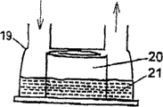
For this reason, Fig. 2-8 has represented the structure of the humidifying container of the output gas that some can provide high-temperature, low relative humidity.Fig. 2 has represented that has been adopted a humidifying container that does not have the hardware 20 (for example, the metal of a spiral web-like) of siphon paper.So just both provided dried heating (passing through hardware), the dampness from the heating of hot water 21 was provided again.In this structure, the container 19 unsaturated gas that provides, this is because some heat that adds that offers gas comes from dried heating by metallic coil.The relative humidity that produces in the container is subjected to the influence of gas channel, metallic coil shape, size and water level, so in use be not easy to any adjusting.Yet container 19 has lower relative humidity and controlled absolute humidity by making output gas, has shown the advantage that can alleviate the phenomenon of condensing really.
Fig. 3 and 4 has represented to provide in the exit other example of the humidifying container of low relative humidity, high-temperature gas.Fig. 3 has represented a container that has used a kind of porous material 22 (for example a kind of porous ceramics), contain water 23 in this porous material 22, thereby can provide heating or humidification function, and Fig. 4 has represented that has been adopted a container that the water in the container 25 is produced the semipermeable membrane 24 of obstructive action.In these two examples, these containers provide by porous material or semi-transparent material and do heating, and the dampness of heating is provided by water simultaneously.In both cases, the ratio of heating and humidification is fixed, can not be regulated simply, removes the supply of unrestricted water.
The represented container of Fig. 5-8 can provide the gas with different relative humidity levels and temperature.In Fig. 5, vario valve 26 allows the ratio of gas flow that we flow through drying by-pass conduit 27 and the gas flow that flows through from the surface of water 28 to regulate.By-pass conduit passes in water, so that gas is heated.These two strands of air-flows converge at outlet 29 places.This is an example of " parallel connection " system, and wherein gas is divided into two strands and heat and humidification by two different passages.In Fig. 6, gas also has been divided in two gas passages by an adjustable valve 30.Wherein a part of air-flow in container 32 water 31 and by humidification, another part gas is then heated by the heater 58 around conduit 33.These two gas passages converge at junction point 34 places.
Vario valve 26 shown in Fig. 5 and 6 and 30 angle can be set to steady state value, can or can be regulated automatically by manual adjustments.The advantage of automatic regulating valve is when matching with discontinuous flow rate, and for example when being used with a respiratory organ, effluent air can have constant humidity from container.The problem that these flow patterns may bring is, because the humidity that the higher gas of flow velocity obtains in container is less, so can cause the humidity of some parts in the breath cycle to be lower than the humidity of other parts.A kind of approach that addresses this problem is to use a flow sensor that responds fast that instantaneous velocity is measured, and regulates the angle of vario valve then rapidly.A kind of practical more method that can obtain this effect is to use spring 70 and the 71 pairs of valves 26 and 30 to carry out spring and loads.The gas that this means low flow rate by-pass conduit of will mainly flowing through, and the gas of high flow rate will be handled and pass through spring-biased valve, thus allow the water of more air-flow in humidifying container.Humidifier can also utilize through the angle of spring-loaded vario valve gas flow speed is measured.
Fig. 7 and 8 has represented the cascaded structure of low relative humidity container, and the dry gas that wherein enters the container 35 of contain hot water 36 can carry out preheating by the heater among Fig. 7 37, perhaps also can be heated by the heater among Fig. 8 38 after flow container.In both cases, heater is all only done heating to gas, and effluent air has lower relative humidity and higher temperature 39 from exporting thereby make.
The container of any low relative humidity shown in Fig. 2-8, high-temperature can use with foregoing moisture control system in this patent is collaborative, but can not successfully be used with humidifier of the prior art, this is because existing humidifier is controlled based on temperature, rather than humidity control.
Adiabatic delivery conduit
Another aspect of the present invention as shown in Figure 9.Herein, low relative humidity shown in Figure 8, humidification system and delivery conduit that do not heated, good adiabatic function of high-temperature are combined togather.Gas enters in the standard humidifying container 36 that water 37 is housed at import 35 places, and wherein water 37 is heated by heating plate 38.Gas reaches capacity in this container substantially, leaves this container by gas outlet 39 then, thereby enters heating duct part 40, and this heating duct part 40 is heated to higher temperature with humid gas, thereby makes it have lower relative humidity.This air-flow is surrounded by the conduit 41 of heat insulation layer 42 through an outside then.Recommend this of heat insulation layer employing to can be used for reducing the lost inside of heat and be filled with the not thin overcoat of moving air.When this conduit pipe with thermal insulation of airflow passes of high-temperature, low relative humidity, the sub-fraction heat is lost by catheter wall, and therefore gas temperature is descended to some extent.Yet control by the heat that heater 40 is produced, just can make the temperature of gas remain on it more than dew point always, thereby avoid in conduit 41, producing the phenomenon of condensing.
The present invention has recommended several different sensor configuration schemes.At first, pick off 43 can be an absolute humidity sensor, is used to control heating plate 38, thereby makes container 36 produce ideal humidity.In one embodiment, pick off 45 is temperature sensors, is used for control heater 40, thereby makes the gas of the pick off 45 of flowing through keep having certain ideal temperature.If this temperature is higher than the dew point temperature of the gas at pick off 43 places, just the phenomenon of condensing can not appear in the conduit 41 so.Yet when humidifier is opened, may originally will there be concretion in the conduit 41.If pick off 45 adopts a humidity sensor to replace a temperature sensor, so just can control the degree that produces the phenomenon of condensing in the conduit 41.The foregoing algorithm that is used for two humidity sensor controls also can be used in native system in this patent.
An alternative arrangement position of absolute humidity sensor is position 44, thus the position of substitution 43.The absolute humidity at 44 places, position should be identical with 43 places, and this is because gas has been subjected to heating, thereby does not lose any moisture.Yet it is very favourable that absolute humidity sensor is arranged in 44 places, and for example pick off can be worked in the lower environment of relative humidity better.This position of absolute humidity sensor can be used with temperature that is arranged in 45 places or absolute humidity sensor.
The humidifier structure that does not have any patient's airway pick off
Another aspect of the present invention relates to the necessity of cancellation at patient's airway place sensor installation.In order to cancel this pick off safely, we must guarantee that the gas that enters delivery conduit has safe temperature and absolute humidity, and guarantee that the temperature of the inner surface of delivery conduit is no more than safe temperature.This that is to say and will make delivery conduit have constant inner wall temperature.
Therefore, thus we needed be a kind of can be by keep the delivery conduit of the heating of ideal temperature from homoiothermic.Heater both can be embedded in the tube wall of delivery conduit, also can abut on the inner chamber of this delivery conduit, perhaps can also wrap in the outside of this delivery conduit.This heater can be processed by positive temperature coefficient (PTC) material (for example " Winterguard " of the Raychem company of California, USA Menlo Park production), so that the resistance that makes this heater increases with the rising of temperature, thereby causes reducing of power.Yet this delivery conduit can the multiple environment of extend past, perhaps can be provided with the local ventilation device on some position of this conduit.If the PTC element is arranged with parallel form, so just can imagine whole advantages that this heater has.If the PTC element arranges that with parallel form the low temperature of this conduit part will have lower resistance so, this will cause more shedding of frequent fever amount.Like this, this conduit is controlled the temperature of oneself with regard to tending to.PTC pipe notion can further extend to one in heating and temperature controlled endotracheal tube.
Figure 10 has represented the structure of a conduit, and this conduit has adopted the elasticity PTC element with the parallel conducting wire structural configuration.Conduit 48 is processed by a kind of elasticity ptc material, and it has two low-resistance connection straps 46 and 47 that are arranged in its both sides.This just makes each part of this pipe fitting all be made up of the short conductors pipeline section that is connected in parallel between conductor 46 and 47.These pipeline sections are used in Figure 10 around the dotted line of this conduit and are represented.Conductor 46 is connected with the power supply 49 of an adjustable voltage with 47, and this power supply can be alternating current power supply or dc source.This conduit has one makes this pipe insulation and adiabatic exterior layer (not shown).Each pipeline section longitudinally can carry out independent regulation to the temperature of oneself, and is not subjected to the influence of the other parts of this conduit.In order to improve this service behaviour, be necessary to process the perpendicular parallel slit 50 of axis of some and this conduit, thereby eliminate the electric interconnection between the different PTC pipeline sections.
Although above imagine and described a kind of design of concrete PTC heating duct, can use the design of other PTC conduit equally.The scheme that another possibility is favourable is to make the PTC conduit have different Temperature Distribution along its length direction, thereby replace stationary temperature to distribute.The design of PTC can also further expand, thereby ptc heater is arranged in the other parts place of patient respiration pipeline, for example, is arranged in the elastic catheter place between the conduit that is connected usually in Y shape connector (opening 17 among Fig. 1) and the patient's trachea.
PTC conduit shown in Figure 10 makes us can process a kind of humidifier that does not use any pick off at patient's airway place.Figure 11 has represented a humidifier structure that has adopted this conduit.Gas enters humidifying container 52 by import 51, and carries out humidification and heating respectively by water 53 and heating plate 54.The temperature of absolute humidity sensor 55 control heating plates 54, thus make the gas of the pick off 55 of flowing through have ideal absolute humidity.PTC conduit 56 is heated by an external voltage (not shown), thereby makes inner surface have constant ideal temperature, and this temperature should be higher than the dew point of gas.Therefore, will have the temperature close from exporting 57 gases that flow out conduit 56, and have the desirable absolute humidity of being controlled by absolute humidity sensor 55 with conduit temperature.
A variation of system shown in Figure 11 is that 55 places have used a temperature sensor in the position.Another variation with conduit of constant temperature inwall is a kind of water of process heating or delivery conduit that other fluid heats of using, and wherein said water or other fluid flow through the smaller conduit of the tube wall inside of this delivery conduit under the effect of pump pressure.Because the fluid of heating is compared with air and is had higher specific heat, so when fluid is flowed through the wall interior conduit of delivery conduit, can keep the temperature of quite stable.
The use of pick off/heater manifold
Traditional humidifier tends to use visits acicular pick off, and pick off just can pass the hole of specially designing and be inserted into the sidewall of breathing pipeline like this, thereby carries out the measurement of temperature.Yet the humidifier structure described in the present invention has been used a plurality of pick offs around the humidifying container, so adopt the manifold 59 as shown in figure 12 will be helpful.
Humidifying container 60 is knockdown pieces, and it can be contained on the humidifier base 61, as shown in figure 12 by sliding.When container 60 by sliding when being contained on the humidifier base 61, its end, contact with heating plate 62, its import simultaneously and export 63 and 64 and contact with the hole 67 and 68 of manifold 59 inside respectively.To be entered this manifold through opening 65 by the dry air of humidification, and flow out these manifolds, and the opening 63 of flowing through enters container 60 through opening 63, in container 60 by humidification.
Leave after the container 60, humid gas passes vessel port 64 and enters manifold opening 68.This humid gas leaves manifold 59 through opening 66 at last, thereby enters the breathing pipeline.
This manifold can be an independently detachable assembly, perhaps also can be an integral part of humidifier base.It can accommodate temperature sensor, humidity sensor, flow sensor or a heating element heater.These assemblies will be disposed in position 72 and 73 places in the manifold 59.Manifold 59 can be heated, thereby prevents condensing of humid gas.It can be connected with 64 with opening 63 as mentioned above simultaneously, perhaps also can only be connected with outlet 64.An advantage using manifold is that many pick offs or heater can be integrated with in simple, the assembly that can clean, and does not need to be inserted into the probe of breathing in the pipeline independent of each other.This has just simplified the connection and the fitting operation of user.Another advantage of manifold is that the temperature and the flow rate of the dry gas of coming in can be recorded easily, and does not need additional probe sensor and be connected.
Change to described structure
Although all adopted absolute humidity sensor in described all the different humidification systems of this patent, also can use relative humidity sensor.This may comprise the control algolithm slightly different with the control algolithm described in this patent.Perhaps, a relative humidity sensor also can be united use with a temperature sensor.The absolute humidity value just can be calculated by rh value and temperature value like this, rather than is directly measured.
The novel humidification system of described in this patent all can be used in combination with additional temperature sensor.This will bring additional benefit, and reserve safety for example were provided when humidity sensor lost efficacy.Another benefit is that the temperature of the gas that flows to patient is remained in certain limits, thereby avoids relative humidity low excessively, even if the absolute humidity of this moment can be accepted.
Similar with it, it also is of great use that the airflow rate of the humidifier of flowing through is measured, because this is an important parameter that influences humidifier control.Therefore, can adopt flow sensor in foregoing any system.A kind of useful flow sensor structure of the prior art is to use a pick off based on the heat loss of thermal element in air-flow.If use the humidity sensor of a heating, this pick off is required in order to reach uniform temperature so adds the flow velocity that heat can be used to determine gas.
The matter of utmost importance that should consider when infection control is the design medical device.For fear of produce bacterial reproduction in the assembly of this humidification system, any and contacted part of air-flow can adopt antibiotic plastic.Contaminated in order to prevent sensor probe, probe portion can be used a droppable sheath, thereby the protection probe avoids breathing being infected with of pathogen in the pipeline.This will be specially adapted to the probe of temperature sensor.Generally speaking, humidity sensor need directly contact with air-flow, so droppable sheath will not be suitable for humidity sensor, unless this humidity sensor is based on optical principle work, unless perhaps this sheath is formed by a kind of materials processing that allows steam permeable but do not allow pathogen to pass through.This protection sheath can be to abandon an integral part of breathing in the pipeline.