CN1299229C - Optical information reading apparatus and related information reading method - Google Patents
Optical information reading apparatus and related information reading method Download PDFInfo
- Publication number
- CN1299229C CN1299229C CNB2004100768563A CN200410076856A CN1299229C CN 1299229 C CN1299229 C CN 1299229C CN B2004100768563 A CNB2004100768563 A CN B2004100768563A CN 200410076856 A CN200410076856 A CN 200410076856A CN 1299229 C CN1299229 C CN 1299229C
- Authority
- CN
- China
- Prior art keywords
- direct light
- image
- reading
- zone
- information code
- Prior art date
- Legal status (The legal status is an assumption and is not a legal conclusion. Google has not performed a legal analysis and makes no representation as to the accuracy of the status listed.)
- Expired - Fee Related
Links
Images


Classifications
-
- G—PHYSICS
- G06—COMPUTING; CALCULATING OR COUNTING
- G06K—GRAPHICAL DATA READING; PRESENTATION OF DATA; RECORD CARRIERS; HANDLING RECORD CARRIERS
- G06K7/00—Methods or arrangements for sensing record carriers, e.g. for reading patterns
- G06K7/10—Methods or arrangements for sensing record carriers, e.g. for reading patterns by electromagnetic radiation, e.g. optical sensing; by corpuscular radiation
- G06K7/14—Methods or arrangements for sensing record carriers, e.g. for reading patterns by electromagnetic radiation, e.g. optical sensing; by corpuscular radiation using light without selection of wavelength, e.g. sensing reflected white light
-
- G—PHYSICS
- G06—COMPUTING; CALCULATING OR COUNTING
- G06K—GRAPHICAL DATA READING; PRESENTATION OF DATA; RECORD CARRIERS; HANDLING RECORD CARRIERS
- G06K7/00—Methods or arrangements for sensing record carriers, e.g. for reading patterns
- G06K7/10—Methods or arrangements for sensing record carriers, e.g. for reading patterns by electromagnetic radiation, e.g. optical sensing; by corpuscular radiation
- G06K7/10544—Methods or arrangements for sensing record carriers, e.g. for reading patterns by electromagnetic radiation, e.g. optical sensing; by corpuscular radiation by scanning of the records by radiation in the optical part of the electromagnetic spectrum
- G06K7/10821—Methods or arrangements for sensing record carriers, e.g. for reading patterns by electromagnetic radiation, e.g. optical sensing; by corpuscular radiation by scanning of the records by radiation in the optical part of the electromagnetic spectrum further details of bar or optical code scanning devices
- G06K7/10881—Methods or arrangements for sensing record carriers, e.g. for reading patterns by electromagnetic radiation, e.g. optical sensing; by corpuscular radiation by scanning of the records by radiation in the optical part of the electromagnetic spectrum further details of bar or optical code scanning devices constructional details of hand-held scanners
Abstract
A guide light indicating a rectangular reading portion, smaller than an imaging visual field of an area sensor, is irradiated on a reading objective. A control unit, under the irradiated guide light, causes the area sensor to capture a first image. Then, the control unit detects the position of the guide light based on captured first image data. Then, with no irradiation of the guide light, the control unit causes the area sensor to capture a second image. The control unit then estimates an existing region of a two-dimensional code in the second image. The control unit selects, as a processing objective, only a code that is completely contained in the reading portion and executes the decode processing only for the selected code. When failed in a reading operation, the control unit expands a processing objective region and executes the decode processing again.
Description
Invention field
The present invention relates to a kind of optical information reading apparatus, this device has and is used to read bar code and other one dimension sign indicating numbers, and the two-dimensional imaging visual field of QR sign indicating number and other two-dimension codes.In addition, the present invention relates to a kind of optical information read method.
Technical background
Usually, sell and commodity stocks, in various systems, use bar code and other one dimension sign indicating numbers or QR sign indicating number and other two-dimension codes widely for Care for Cargo.In order to read these sign indicating numbers optically, conventional optical information reading apparatus generally has area sensor, and is set to pocket two-dimension code reading device (being portable terminal), and this device makes the user can carry out manual read operation.According to such optical information reading apparatus, reading section is provided in its front end, thereby can being arranged on this reading section, the user reads near the two-dimension code that writes down on the object or print, this reads object such as catalogue, voucher and Commercial goods labels.In this case, the user operates trigger switch, so that reading device begins two-dimension code etc. is carried out the image pick-up operation of imaging and reads the read operation of (decoding) yard image that is picked up.
In recent years, need said system to use the sign indicating number of high compaction, thereby many information codes can be recorded in the limited zonule.In order to satisfy these needs, a kind of like this trend is arranged, promptly the sign indicating number reading device uses the area sensor of pixel quantity increase to improve resolution.But,, will be created in so in the same imaging viewing field and may write down a plurality of yards problem simultaneously if the two-dimension code size is dwindled.This is not desirable, because do not want other yards that read and must carry out the unnecessary processing of reading in order to read the user.In addition, when the pixel count of area sensor was big, this decoding processing can take a long time.
Simultaneously, conventional reading device provides a kind of subregion read mode, and this pattern makes device be positioned at the sign indicating number of the center section of area sensor imaging viewing field on only can reading along the longitudinal direction.According to this conventional equipment,, can read-onlyly take the sign indicating number that the family is wanted reading under a plurality of yards the situation that existence is arranged with multistage pattern (multi-stage pattern) on the target (for example) with reference to Japanese Patent Application Publication 2002-92542.
In addition, another kind of conventional reading device is arranged, this device is divided into a plurality of with the captured image zone, thereby detects the existence zone of sign indicating number in the captured image effectively, and carries out detecting operation in detected existence zone.According to the reading device of this routine, can shorten the processing time (for example, with reference to corresponding to United States Patent (USP) the 6th, 678,412 Japanese Patent Application Publication 2000-353210).
But under the situation of the subregion read mode of describing in providing as Japanese Patent Application Publication 2002-92542, this pattern is very effective under the situation that bar code is arranged along the longitudinal direction.But if two-dimension code is pressed close to each other along left and right directions, then the problem of Chu Xianing is, selects sign indicating number to be read very difficult in two-dimensional space.The leeway that the further shortening processing time is arranged in addition.According to a kind of prior art in back, it is characterized in that inferring the existence zone of this yard, also leaveing some room for improvement aspect shortening the processing time.
Summary of the invention
Consider the problems referred to above of prior art, an object of the present invention is to provide a kind of optical information reading apparatus, this device can exist in two-dimensional space selects the user to want the sign indicating number that reads at an easy rate under a plurality of yards the situation, can also shorten the processing time.
In order to realize above-mentioned relevant purpose with other, the invention provides a kind of optical information reading apparatus, this device comprises image pick-up device, direct light irradiation unit, treating apparatus and pick-up unit.This image pick-up device has the two-dimensional imaging visual field, reads the image of target with record, and this reads the sign indicating number that target includes record or is printed thereon.Provide the direct light irradiation unit to be used for direct light shone and read target, to show reading section.Provide treating apparatus to carry out the processing of reading of sign indicating number according to the image that image pick-up device was picked up.The direct light that penetrates from the direct light irradiation unit marks the 2 dimensional region as reading section, and this reading section is narrower than imaging viewing field.Provide pick-up unit to detect the irradiation position of direct light on the imaging viewing field of image pick-up device.When having a plurality of yards in the 2 dimensional region shown in the direct light, treating apparatus reads the target of processing according to the sign indicating number conduct that the testing result of pick-up unit is mainly selected to be completely contained in this 2 dimensional region.
According to this device, the direct light irradiation unit is configured such that direct light shines reads on the target, to mark the 2 dimensional region of representing reading section.The user is arranged on reading device and reads target proximity, so that this device readout code.The mode that the user adjusts this setting position makes when document image, obtains in the 2 dimensional region that is marked by direct light from the sense code for the treatment of that reads target.Therefore, the present invention makes this device can easily select and read expection sign indicating number to be read from read target.
When images acquired, from the optical axis of the direct light of direct light irradiation unit emission and the optical axis inconsistent physically (being relative tilt) of the light of image pick-up device reception.Therefore, according to this device with read variable in distance between the target, the irradiation position of direct light moves on the imaging viewing field of image pick-up device.On the other hand, the invention provides pick-up unit, this device is used to detect the irradiation position of direct light on the imaging viewing field of image pick-up device.Therefore, the present invention can make reading device collect really to be arranged in 2 dimensional region that direct light marks and as reading the sign indicating number of processing target, and can not be subjected to the restriction of the position of direct light irradiation unit.In addition, when having a plurality of yards in by the 2 dimensional region shown in the direct light, wherein this 2 dimensional region is as reading section, and narrower than imaging viewing field, and treating apparatus of the present invention mainly selects to be completely contained in sign indicating number in the 2 dimensional region as reading processing target.Therefore, the present invention can limit the image-region that becomes processing target.Just the processing time can be shortened.
In this case, can arrange the direct light irradiation unit, make to have line in irradiation in the projection of 2 dimensional region periphery, line segment, or the light of some shape perhaps to the whole area illumination light of 2 dimensional region, mark the 2 dimensional region as reading section thus.Under any circumstance, the user can discern the 2 dimensional region that marks to reading section at an easy rate.
In addition, the present invention provides a kind of device of practicality for above-mentioned detection device, and this pick-up unit is used to detect the irradiation position of direct light on the imaging viewing field of image pick-up device.Preferably shine the situation hypograph pick device that reads on the target and gather first image, and do not shine collection second image under the situation about reading on the target in direct light subsequently in direct light.Pick-up unit obtains the irradiation position of direct light on imaging viewing field according to the data of first image, and judges position identical with the irradiation position of direct light on second image.According to this device, the present invention makes reading device can utilize relative simple proposal to detect the position of direct light on the imaging viewing field of image pick-up device fully.
In addition, can be provided with above-mentioned treating apparatus, make the zone by the captured image of image pick-up device collection be divided into a plurality of, check the bright dark degree and the bright dark degree change of each pixel in each image block, and,, the relevant possibility that comprises at least a portion sign indicating number in each image block judges the existence zone of inferring sign indicating number by being made according to the result of checking procedure.
Utilize this device, the existence zone of the sign indicating number that the present invention can infer reading device to comprise in the captured image roughly.This might reduce fully or limit as the zone of reading processing target.Processing time can further shorten.
In addition, treating apparatus is preferably only selected by the image that is comprised in the 2 dimensional region that direct light marked as the processing target image.Utilize this device, can shorten the processing time.In addition, when a plurality of sign indicating numbers were completely contained in the 2 dimensional region that is marked by direct light, treating apparatus was preferably selected to read processing target with the immediate sign indicating number conduct of 2 dimensional region center position.Utilize this device, not only can shorten the processing time, and reading device can read the user really and wants the sign indicating number that reads.
In addition, when treating apparatus can not readout code, and the reason of failure is when coming from the part sign indicating number and being positioned at outside the 2 dimensional region that is marked by direct light, and this treating apparatus preferably outwards enlarges the processing target zone from this 2 dimensional region, the processing target zone that has enlarged is carried out once more read processing then.Utilize this device, even the user is inaccurate to sign indicating number location with respect to direct light, the also fault (that is error) in the blanking code read operation almost.In addition, carry out once more when treating apparatus and to read when handling, it preferably enlarges the processing target zone, thereby comprises the zone adjoining with there being the zone, infers that wherein this exists the zone to contain sign indicating number.Utilize this device, can prevent that the processing target zone from unnecessarily being widened, and therefore can prevent that the processing time from becoming unnecessarily long.
In addition,, the invention provides a kind of method that is used for the optically reading information sign indicating number, comprise following seven steps in order to realize above-mentioned relevant purpose with other.
First step is used to shine direct light to mark the two-dimentional reading section that reads on the target, and this part is less than the imaging viewing field of image pick-up device.Second step is used for gathering first image that reads target under the irradiation of direct light.Third step is used for detecting according to first view data of gathering the position of direct light.The 4th step is used for gathering second image that reads target after direct light stops to shine.The 5th step is used for inferring the existence zone of the second image information code.The 6th step is used for when a plurality of sign indicating number is positioned at the two-dimentional reading section that is marked by direct light, only selects to be completely contained in information code in the two-dimentional reading section as processing target.The 7th step is used for only the information code of selecting being carried out decoding processing.
Direct light preferably has line in the projection that limits two-dimentional reading section periphery, line segment, or the shape of point.Perhaps, direct light is the light in the whole zone of the two-dimentional reading section of irradiation.
Optical information read method of the present invention is preferably further comprising the steps of: the data according to first image obtain the irradiation position of direct light on imaging viewing field, and judge that the same position on second image is the direct light irradiation position.
Optical information read method of the present invention is preferably further comprising the steps of: the zone of the captured image of image pick-up device collection is divided into a plurality of, and check the bright dark degree and the bright dark degree change of each pixel in each image block, and according to the result of checking procedure, by making the existence zone that correlated judgment is inferred information code to comprising at least the possibility of partial information sign indicating number in each image block.
Optical information read method of the present invention is preferably further comprising the steps of: be chosen in the image that comprises in the two-dimentional reading section that is marked by direct light as the processing target image.
Optical information read method of the present invention is preferably further comprising the steps of: when a plurality of information codes are completely contained in the two-dimentional reading section that is marked by direct light, select to read processing target with the immediate information code conduct of two-dimentional reading section center position.
Optical information read method of the present invention is preferably further comprising the steps of: under can not the situation of sense information sign indicating number, and when the reason of failure stems from the partial information sign indicating number and is positioned at outside the two-dimentional reading section that is marked by direct light, the processing target zone is outwards enlarged from two-dimentional reading section, carry out for the processing target zone that enlarges then and read processing.
In this case, read in the processing procedure, preferably enlarge the processing target zone, thereby make it comprise the zone adjoining, infer that wherein this exists the zone to contain sign indicating number with there being the zone in execution.
The accompanying drawing summary
By detailed description below in conjunction with accompanying drawing, above-mentioned and other purposes of the present invention, feature and advantage will be more apparent, wherein:
Fig. 1 is for representing according to one embodiment of the invention the process flow diagram of handling procedure in the sign indicating number read operation;
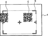
Fig. 2 A and 2B are respectively on the expression imaging viewing field view of the example of position relation between two-dimension code and the direct light;
Fig. 3 is the block diagram of the electronics layout of schematically illustrated two-dimension code reading device according to the preferred embodiment of the present invention;
Fig. 4 is the longitudinal cross-section view of demonstration according to the mechanical arrangement of the two-dimension code reading device of the preferred embodiment of the present invention;
The synoptic diagram that Fig. 5 changes the direct light occurrence positions for explanation according to the variation of reading distance;
Fig. 6 is used to infer that according to the preferred embodiment of the present invention there is the view of the processing in zone in two-dimension code for explanation;
Fig. 7 for explanation when the image section ground of two-dimension code is positioned at outside the reading section, according to the view in the processing target zone of preferred embodiment of the present invention expansion; And
Fig. 8 is corresponding with Fig. 2 A and 2B but the view of expression another embodiment of the present invention.
Detailed Description Of The Invention
Hereinafter with reference to description of drawings each preferred embodiment of the present invention.
Hereinafter, according to manual type (hand-operated type) (being pocket) two-dimension code reading device is described referring to figs. 1 through 7 one embodiment of the present of invention.
Fig. 4 is the figure that schematically shows the mechanical arrangement of two-dimension code reading device 1, and described sign indicating number reading device is as the optical information reading apparatus according to present embodiment.Two-dimension code reading device 1 comprises reading mechanism 3 and the control module 4 (with reference to figure 3) that is combined in the housing 2.Equipment reading mechanism 3 is to read in catalogue, and voucher, Commercial goods labels or other read the two-dimension code C as the QR sign indicating number (with reference to figure 2A and 2B) that writes down on the target.Control module 4 is mainly arranged by microcomputer, in order to system is totally controlled, and play treating apparatus, described treating apparatus reads processing (and decoding processing) according to the view data that reading mechanism 3 (being area sensor) picks up to two-dimension code C.
Housing 2 forms the part (grip portion) of holding with a firm grip at its near-end (that is, the right side among the figure), and broadens a little at its front end.The front portion of housing 2 also is bent downwardly a little, thereby extends forward with angle of declination.The leading section of housing 2 has the hole of reading 2a.The key input part of being made up of a plurality of keyswitch 5a 5 is arranged on the upper surface of housing 2.This key input part 5 makes the user can select the type of fetch program and designated code.
In addition, except keyswitch 5a, housing 2 has the trigger switch 6 (only shown in Figure 3) that is used to read instruction, and this trigger switch 6 is arranged on the outside surface of housing 2 (for example on the side).For example, this trigger switch 6 is set to cause two-step action when the user presses it.Although can illustrate in greater detail in the back, user's phase one is pressed action (being what is called half down state of switch) makes system begin the irradiation operation of direct light, and user's subordinate phase is pressed action makes system carry out read operation.
In addition, display part 7 is arranged on the upper surface of housing 2, and this display part for example is arranged to LCD (being LCD).These keyswitches 5a and display part 7 are installed on the printed circuit board (PCB) 8 that places housing 2.Although do not illustrate among the figure, control module 4 also is installed on the printed circuit board (PCB) 8.Although do not illustrate among the figure, the accumulator that is used as power supply is also coupled in the housing 2.
Reading mechanism 3 comprises area sensor 9, image pickup lens 10, a plurality of emitting led (being light emitting diode) 11 and a plurality of lighting lens 12.Area sensor 9 for example is arranged to CCD (being charge-coupled image sensor) image pick-up element, so that as image pick-up device of the present invention.Image pickup lens 10 is arranged on the front of area sensor 9.In the sign indicating number read operation, each emitting led 11 all is used as radiative light emitting source.Each illuminating lens 12 was positioned at before corresponding emitting led 11.
In this case, area sensor 9 is made as has two-dimensional imaging visual field F, and for example, F forms (with reference to Fig. 2 A, 2B and 5 to 7) by horizontal 640 pixels * vertical 480 pixels.Although be not shown specifically, image pickup lens 10 places the center of reading hole 2a, and a plurality of lighting lens 12 place (for example being positioned at part obliquely) around it.
Utilize this device, the user will read hole 2a place read object (voucher, label, catalogue etc.) near, sign indicating number C record or be printed on this and read on the target carries out read operation then, promptly connects trigger switch 6.Response user's operation, system makes LED 11 irradiations read target.In this case, area sensor 9 is gathered the image (that is, carrying out image pick-up operation) that reads target.Then, according to the view data of picking up, 4 pairs of these two-dimension codes of control module C carries out and reads (decoding) processing.
As shown in Figure 5, reading mechanism 3 comprises direct light laser diode 13 and the floodlight lens 14 as the direct light irradiation unit.For example, direct light laser diode 13 and floodlight lens 14 are arranged on area sensor 9 side of (with image pickup lens 10) (for example, among the figure being the left side).Shown in Fig. 2 A and 2B, they are to reading target irradiation direct light G to mark reading section.
Reading section is set to the rectangle 2 dimensional region, and this zone is less than the imaging viewing field F of area sensor 9.Direct light G is the line segment light of the periphery (being framework) of this 2 dimensional region of expression.More specifically, according to this embodiment, the cross light that direct light G marks two T shape light parts at this 2 dimensional region left side and center, right side and marks the center of this 2 dimensional region by four that limit four angles of 2 dimensional region L shaped light parts, is respectively partly formed.
The optical axis O inconsistent physically (that is relative tilt) of the light that the optical axis P of direct light irradiation unit (being direct light laser diode 13) and area sensor 9 are received.Therefore, as shown in Figure 5, according to the variation of reading hole 2a and reading distance between the target, the irradiation position of direct light G moves on the imaging viewing field F of area sensor 9.More specifically, when reading hole 2a and read distance between the target when lacking (being distance L 1), the direct light G of irradiation is towards the left side skew of imaging viewing field F.On the other hand, when reading hole 2a and read distance between the target when growing (being distance L 2), the direct light G of irradiation is towards the right side skew of imaging viewing field F.
Fig. 3 is the circuit diagram that schematically shows the electric layout of two-dimension code reading device 1, and described device comprises the control module 4 as critical piece.Control module 4 is with the operation signal input of key input part 5 and trigger switch 6, and control display part 7.Control module 4 control each emitting led 11 and direct light laser diode 13.
Control module 4 will be imported by the captured image data that read target that area sensor 9 is gathered, and carry out decoding processing.Although do not illustrate among the figure, control module 4 also comprises amplifier, is used for the image pickup signal of magnification region sensor 9; And binary circuit, be used for sensor signal is become binary coded data.Video memory 15 links to each other with area sensor 9 with control module 4.Control module 4 links to each other with audible segment 16, and this audible segment produces buzzer when finishing the read operation of two-dimension code C.Control module 4 also links to each other with data communication part 17, and this communications portion is carried out the data communication of decoded data via infrared ray and external unit.
Two-dimension code reading device 1 utilizes the software service (promptly carrying out the fetch program) of control module 4 to carry out following operation.More specifically, when the user with half down state operation trigger switch 6 (promptly respond the user phase one press action), control module 4 activates direct light laser diodes 13, is radiated at and reads on the target so that will mark the direct light G of reading section (being 2 dimensional region).Then, to press fully trigger switch 6 make response (promptly respond the user subordinate phase press action), control module 4 makes area sensor 9 gather the image that reads target.The collection of image is divided into two stages.In the phase one, be radiated at direct light G (that is, under the situation that does not have the irradiating illumination light beam) under the situation about reading on the target, area sensor 9 is gathered first image.Then, in subordinate phase, be not radiated at direct light G (that is, under the situation of irradiating illumination light beam) under the situation about reading on the target, area sensor 9 is gathered second image.
In this case, control module 4 obtains the irradiation position of direct light G on imaging viewing field F according to the view data of first image, and will be on second image identical position be used as the irradiation position of direct light G.In first image, the irradiation position of direct light G is compared enough bright with other positions.Therefore, be easy to distinguish the position of direct light G according to the brightness of view data.Therefore, control module 4 can play the effect of pick-up unit of the present invention.
Then, control module 4 reads processing (decoding processing) according to the view data of second image to two-dimension code C.In this case, according to the detection position of direct light G in above-mentioned imaging viewing field F, control module 4 specifies the two-dimension code C that is comprised in the direct light G reading section (being 2 dimensional region) as processing target.Exist in 2 dimensional region under the situation of a plurality of yards C, the control module 4 main two-dimension code C that are completely contained in the 2 dimensional region that specify are as reading processing target.In addition, according to this embodiment, in carrying out decoding processing, control module 4 is at first carried out the processing that is used for inferring in the existence zone of the second image two-dimension code C, and there is the bright and dark pattern in the zone in the two-dimension code C that reads supposition then.
Although in detail do not explain, carry out the processing in the existence zone that is used to infer two-dimension code C, as in Fig. 6 and 7 partly shown in.That is, control module 4 is divided into the pickup area of captured image (i.e. second image) longitudinally a plurality of image block B (being Examination region) that arrange with horizontal direction.Then, the bright dark degree of each pixel among control module 4 each image block B of check, and bright dark degree change.Then, according to its result (being bright and the quantity of dark change point), control module 4 extracts and may contain more greatly to the image block B of small part two-dimension code C.For example, each image block B has the size of 16 pixels * 16 pixels.Relevantly be used to infer the processing that has the zone, the applicant has proposed as disclosed detailed process in Japanese Patent Application Publication 2002-304594 number or the Japanese Patent Application Publication 2000-353210 number.
In addition, according to this embodiment, when it carried out decoding processing, control module 4 only specified in the image that comprised in the 2 dimensional region that direct light G marks as the processing target image.When it can not read (decoding) two-dimension code C, and the reason of failure is when coming from part two-dimension code C and being positioned at outside the 2 dimensional region that is marked by direct light G, control module 4 outwards enlarges the processing target zone from 2 dimensional region, carries out once more for the processing target zone that enlarges then and reads processing.Then, carry out once more when it and to read when handling, control module 4 enlarges the processing target zone, thereby it is comprised and zone that this 2 dimensional region is contiguous, and wherein this 2 dimensional region of this supposition comprises two-dimension code C (with reference to Fig. 7).
Next, the function of said apparatus is described with reference to figure 1.According to two-dimension code reading device 1 according to the above embodiment of the present invention, in reading and recording or be printed in the process of the two-dimension code C that reads on the target, the user moves the hole 2a that reads of housing 2 towards reading target, in this case, the user is pressed into half down state with the trigger switch 6 that is provided with on housing 2 sides.This user who is applied to trigger switch 6 presses action the phase one and system is shone direct light G read on the target, thereby marks reading section as mentioned above (being 2 dimensional region).Therefore, the user can be positioned at the two-dimension code C to be read of expection in the 2 dimensional region that is marked by direct light G, the reading section of visually confirming simultaneously to read on the target and being marked.Then, the user does subordinate phase to trigger switch 6 and presses action.
Control module 4 is carried out according to process flow diagram shown in Fig. 1 and is read processing.More specifically, shown in step S1, shining under the situation about reading on the target at direct light G (is not promptly having under the situation of irradiating illumination light beam), and control module 4 makes area sensor 9 carry out the collection of first image.Then, in step S2, according to first view data of gathering, the processing that control module 4 is carried out is used to obtain the irradiation position (that is, limit the 2 dimensional region of reading section) of direct light G on imaging viewing field F.This system that makes is easy to detect the position of direct light G, even as shown in Figure 5, according to reading hole 2a and reading the variation of distance between the target position of the direct light G that area sensor 9 gathered is moved on imaging viewing field F.
Subsequently, in step S3, control module 4 is stopped using direct light laser diode 13, to stop transmit steering light G.The substitute is, under the situation that reads target, it is emitting led 11 that control module 4 is connected, and make area sensor 9 gather second image in illumination beam.After the collection of second image was finished, control module 4 advanced to next step S4, handled to carry out, and described processing is used for inferring the existence zone (that is the 2 dimensional region that is marked by direct light G) of the image of the reading section two-dimension code C on imaging viewing field F.When carrying out this processing, control module 4 is divided into as mentioned above longitudinally a plurality of image block B (with reference to figure 6 and 7) that arrange with horizontal direction with the zone of second image, and checks the bright dark degree of each pixel among each image block B, and bright dark degree change.For example, according to the example shown in Fig. 6, comprise the pixel data that bright dark degree changes by thick line area surrounded ' A '.Therefore, control module 4 is inferred the existence zone of zone ' A ' as two-dimension code C.
In step S5, control module 4 specifies the two-dimension code C conduct that comprises in the reading section (that is, 2 dimensional region) to read target, and the target that reads of appointment is carried out decoding processing.Only the processing target image that is comprised in the 2 dimensional region that direct light G is marked carries out this decoding processing.In this case, second image can comprise a plurality of (for example two) two-dimension code C, they are positioned on the imaging viewing field F as shown in Fig. 2 A.In this case, if a two-dimension code C is completely contained in (being in the 2 dimensional region) in the reading section, then processing target is read in control module 4 its conducts of main appointment.Therefore, control module 4 selects to be positioned at the two-dimension code C on figure right side as reading target.Consider that by this when the two-dimension code of gathering had identical size, control module 4 was chosen in the two-dimension code C that comprises maximum area in the reading section, and the sign indicating number of selecting is carried out decoding processing.
Simultaneously, according to the example shown in Fig. 2 B, control module 4 selects to be positioned at the two-dimension code C in figure left side as reading target.
As above-mentioned conspicuous, the target area of decoding processing is not equal to the whole zone of imaging viewing field F, and be restricted to (promptly than the narrower reading section of the imaging viewing field F of area sensor 9,2 dimensional region), and further be restricted to existence zone (that is the zone of representing by thick line ' A ' among Fig. 6) by above-mentioned steps S4.Therefore, can correspondingly shorten the processing time.
Then, in step S6, whether control module 4 is judged for the decoding processing of selected two-dimension code C successful.When decoding processing when success (being among the step S6), then control module 4 output decoder data in next step S9.For example, control module 4 makes display part 7 show decoded data, and decoded data is sent to the computing machine of management.Then, control module 4 finishes the handling procedure of process flow diagram shown in Fig. 1.On the other hand, as shown in Figure 7, there is a kind of situation, promptly because failure of the positioning action of user's images acquired or other reasons may make the image section of two-dimension code C be positioned at outside the reading section (being 2 dimensional region).Therefore in this case, two-dimension code C partly is positioned at outside the processing target image, and the decoding processing to it will finish (be among the step S6 not) unsuccessfully.
Therefore, when decoding was unsuccessful, control module 4 advanced to step S7, so that the processing target zone is outwards enlarged from present reading section (being 2 dimensional region).Then, in step S8, control module 4 is carried out decoding processing once more, and turns back to step S6.Make in the process that the processing target zone widens at step S7, control module 4 enlarges the processing target zone by the part of adding selectively near certain zone, infers that wherein this zone comprises the two-dimension code C that is arranged in the image-region (being image block B) of (promptly along its periphery) beyond this 2 dimensional region.According to the example shown in Fig. 7, control module 4 is by increasing part A ' enlarge processing target zone, wherein this part A ' is made up of a plurality of B, and is expressed as along the hatched area of the upside existence of reading section (being 2 dimensional region).According to this adjustment, control module 4 can carry out decoding processing fully.
Therefore, in addition two-dimension code C with respect to the coarse situation in the location of direct light G under, unless two-dimension code C is positioned at beyond the imaging viewing field F fully, otherwise control module 4 can not read two-dimension code C.In addition, carrying out once more in the decoding processing, control module 4 does not need to enlarge widely the processing target zone, so that comprises unwanted zone.Therefore, can prevent that the processing time is elongated.
As mentioned above, this embodiment uses direct light G to limit the 2 dimensional region narrower than the imaging viewing field F of area sensor 9, and irradiation direct light G is to mark the reading section that reads on the target.This embodiment detects the irradiation position of direct light G on imaging viewing field F, and the two-dimension code C that comprises in the 2 dimensional region of only selecting to be marked by direct light G is as reading processing target.Therefore, this embodiment makes system can be easy to select the two-dimension code C that expects, this yard is one that wants among a plurality of two-dimension code C of existing in two-dimensional space of user to read.In addition, this embodiment makes system can limit or reduce image-region as processing target.Therefore, this embodiment can shorten the processing time.
In addition, this embodiment image-region that area sensor 9 is picked up is divided into a plurality of image block B.The assay that this embodiment changes according to bright dark degree and bright dark degree for pixel among each image block B is inferred the existence zone of two-dimension code C.Therefore, this embodiment can reduce fully as the zone of reading processing target system.Can further shorten the processing time.
In addition, the image that is comprised in the 2 dimensional region that this embodiment only selects to be marked by direct light G is as the processing target image.But, reading under the situation of two-dimension code C failure, this embodiment outwards enlarges the processing target zone comprising adjacent domain, and carries out decoding processing once more.Therefore, though the user with respect to direct light G to the location of two-dimension code C when inaccurate, this embodiment also can eliminate the error that reads of this two-dimension code C.In addition, this embodiment can prevent that the required in the case processing time is elongated.
Fig. 8 is the view that shows another embodiment of the present invention.According to this embodiment, write down or be printed on a plurality of two-dimension code C that read on the target be set between standoff distance shorter relatively.These a plurality of (in the son being two under this example) two-dimension code C is arranged in imaging viewing field F fully and goes up the 2 dimensional region that is marked by direct light G.In this case, control module 4 specify with the immediate two-dimension code C of 2 dimensional region center position as reading processing target (promptly among the figure one of the right).
According to this device, the user only need be provided with two-dimension code C to be read or be positioned at the center near the 2 dimensional region that is marked by direct light G.Therefore, not only this embodiment can reduce the processing time, and this embodiment makes the user can only finish the processing of reading for the two-dimension code C that means really.
According to the foregoing description, reading under the situation of two-dimension code C failure, control module 4 outwards enlarges the processing target zones, and comprising adjacent domain, and actuating code is handled once more.But, under the situation of read operation failure, also wish to notify the user any error that reads, thereby allow the user carry out read operation once more.More specifically, wish only to specify the sign indicating number conduct that is completely contained in the 2 dimensional region that marks by direct light G to read processing target.In addition, preferably be provided for measuring from housing 2 (promptly reading hole 2a) to the device that reads distance the target (promptly reading distance).In this case, for example, can revise pick-up unit according to the distance that reads that records, thereby obtain the position of direct light G on imaging viewing field F indirectly.
The present invention is not limited to the foregoing description.For example, for the irradiation pattern of direct light, the light that also can shine the shape with many line segments or a plurality of points in projection is used for along the peripheral framework that limits of 2 dimensional region.Also can use the whole 2 dimensional region of rayed.In addition, optical information reading apparatus according to the present invention is not limited to be used for the read operation of two-dimension code, therefore can be used to read bar code or other one dimension sign indicating numbers.Consider that through this abundant modification that can carry out the present invention is also implemented under the condition that does not break away from main idea of the present invention.
Claims (14)
1, a kind of optical information reading apparatus comprises:
Image pick-up device has the two-dimensional imaging visual field, is used to gather the image that reads target, and this reads target and comprises record information code thereon;
The direct light irradiation unit is used for direct light is shone the described target that reads, to mark reading section; And
Treating apparatus, the image that is used for picking up according to described image pick-up device carries out the processing of reading of described information code,
It is characterized in that
The direct light that penetrates from described direct light irradiation unit marks the 2 dimensional region as reading section, and this reading section is narrower than described imaging viewing field,
Pick-up unit is used to detect the irradiation position of described direct light on the described imaging viewing field of described image pick-up device, and
When having a plurality of yards in this 2 dimensional region that is marked by described direct light, described treating apparatus reads processing target according to the information code conduct that the testing result of described pick-up unit is mainly selected to be completely contained in the described 2 dimensional region;
When a plurality of sign indicating numbers were completely contained in the described 2 dimensional region that is marked by described direct light, the information code that described treating apparatus is selected and described 2 dimensional region center position is nearest was as the described processing target that reads.
2, optical information reading apparatus according to claim 1, wherein said direct light irradiation unit is set to: have line along irradiation in the projection of described 2 dimensional region periphery, line segment, or the light of some shape, perhaps, mark 2 dimensional region thus as described reading section to the whole area illumination light of described 2 dimensional region.
3, optical information reading apparatus according to claim 1 and 2, wherein
Described image pick-up device shines in described direct light and gathers first image under the described situation about reading on the target, and do not shine in described direct light subsequently and gather second image under the described situation about reading on the target, and
Described pick-up unit obtains the irradiation position of described direct light on described imaging viewing field according to the data of described first image, and judges position identical with the irradiation position of described direct light on described second image.
4, optical information reading apparatus according to claim 1, wherein described treating apparatus is set to: the zone of the captured image of described image pick-up device collection is divided into a plurality of, check the bright dark degree and the described bright dark degree change of each pixel in each image block, and,, the relevant possibility that comprises the described information code of at least a portion in described each image block judges the existence zone of inferring described information code by being made according to the result of this checkout procedure.
5, the described image that comprises in the described 2 dimensional region that optical information reading apparatus according to claim 1, wherein said treating apparatus are only selected to be marked by described direct light is as the processing target image.
6, optical information reading apparatus according to claim 1, when described treating apparatus can not read described information code, and the reason of failure is when coming from the described information code of part and being positioned at outside the described 2 dimensional region that is marked by described direct light, wherein this treating apparatus outwards enlarges the processing target zone from described 2 dimensional region, then the described processing of reading is carried out in the processing target zone that enlarges once more.
7, optical information reading apparatus according to claim 6, carry out once more when described treating apparatus and to read when handling, wherein this treating apparatus enlarges described processing target zone, thereby it is comprised and is speculated as the zone that has region adjacent that includes described information code.
8, a kind of method that is used for reading optically information code may further comprise the steps:
The irradiation direct light marks the two-dimentional reading section that reads on the target, and this part is less than the imaging viewing field of image pick-up device;
Under the irradiation of described direct light, gather described first image that reads target;
Detect the position of described direct light according to this first view data of gathering;
After stopping to shine, described direct light gathers described second image that reads target;
Infer the existence zone of information code in this second image;
When having a plurality of yards in the described two-dimentional reading section that marks by described direct light, only select to be completely contained in information code in the described two-dimentional reading section as processing target; And
Only the described information code of selecting is carried out decoding processing;
When comprising a plurality of information code fully in the two-dimentional reading section that is marked by described direct light, selection and the immediate information code of described two-dimentional reading section center position are as the described processing target that reads.
9, optical information read method according to claim 8, wherein said direct light has line in the projection that limits described two-dimentional reading section periphery, line segment, or the shape of point, perhaps described direct light is the light in the whole zone of the described two-dimentional reading section of irradiation.
10, each described optical information read method in 9 according to Claim 8, further comprising the steps of:
Data according to described first image obtain the irradiation position of described direct light on described imaging viewing field,
Judgement position identical on described second image with the irradiation position of described direct light.
11, optical information read method according to claim 8, further comprising the steps of:
The zone of captured image that will be by described image pick-up device collection is divided into a plurality of,
Check the bright dark degree and the described bright dark degree change of each pixel in each image block, and
According to the result of described checking procedure, by the relevant possibility that comprises the described information code of at least a portion in described each image block is made judgement, to infer the zone that exists of described information code.
12, optical information read method according to claim 8, further comprising the steps of: as to be chosen in the image that comprises in the described two-dimentional reading section that marks by described direct light as the processing target image.
13, optical information read method according to claim 8, further comprising the steps of: under the situation that can not read described information code, and when the reason of failure stems from the described information code of part and is positioned at outside the described two-dimentional reading section that is marked by described direct light, the processing target zone is outwards enlarged from described two-dimentional reading section, the processing target zone that enlarges is carried out read processing then.
14, optical information read method according to claim 13 wherein reads when handling in execution, the processing target zone is enlarged, thereby it is comprised and be speculated as the zone that has region adjacent that comprises described information code.
Applications Claiming Priority (2)
| Application Number | Priority Date | Filing Date | Title |
|---|---|---|---|
| JP2003315537A JP4058529B2 (en) | 2003-09-08 | 2003-09-08 | Optical information reader |
| JP315537/2003 | 2003-09-08 |
Publications (2)
| Publication Number | Publication Date |
|---|---|
| CN1595421A CN1595421A (en) | 2005-03-16 |
| CN1299229C true CN1299229C (en) | 2007-02-07 |
Family
ID=34131933
Family Applications (1)
| Application Number | Title | Priority Date | Filing Date |
|---|---|---|---|
| CNB2004100768563A Expired - Fee Related CN1299229C (en) | 2003-09-08 | 2004-09-08 | Optical information reading apparatus and related information reading method |
Country Status (5)
| Country | Link |
|---|---|
| US (1) | US7503492B2 (en) |
| EP (1) | EP1513095B1 (en) |
| JP (1) | JP4058529B2 (en) |
| KR (1) | KR100626329B1 (en) |
| CN (1) | CN1299229C (en) |
Families Citing this family (29)
| Publication number | Priority date | Publication date | Assignee | Title |
|---|---|---|---|---|
| US7721966B2 (en) * | 2004-10-18 | 2010-05-25 | Datalogic Scanning, Inc. | System and method of optical reading employing virtual scan lines |
| JP4254724B2 (en) * | 2005-02-16 | 2009-04-15 | 株式会社デンソーウェーブ | Bar code reading method and computer program |
| KR100784200B1 (en) * | 2005-10-24 | 2007-12-11 | 주식회사 케이티프리텔 | Method and Device for decoding the code having code information according to image |
| CN101237638B (en) * | 2007-02-02 | 2013-01-30 | 银河联动信息技术(北京)有限公司 | Dynamic information distribution system and method |
| JP2009129227A (en) * | 2007-11-26 | 2009-06-11 | Toshiba Mach Co Ltd | Control device, machine tool, and display method |
| JP4968043B2 (en) * | 2007-12-19 | 2012-07-04 | 株式会社デンソーウェーブ | Optical information reader |
| US8074173B2 (en) | 2008-05-08 | 2011-12-06 | Microsoft Corporation | Associating input with computer based content |
| JP5104713B2 (en) * | 2008-10-17 | 2012-12-19 | 株式会社デンソーウェーブ | Optical information reader |
| JP5083676B2 (en) * | 2010-02-16 | 2012-11-28 | 株式会社デンソーウェーブ | Reading system and optical information reading apparatus |
| CN101885391B (en) * | 2010-06-04 | 2012-05-30 | 北京赛腾工业标识系统有限公司 | Device and method for acquiring product coded identifier information |
| JP5130387B2 (en) | 2010-08-26 | 2013-01-30 | 東芝テック株式会社 | Code reader and product information processing system |
| JP2012073822A (en) * | 2010-09-29 | 2012-04-12 | Panasonic Corp | Form reading device |
| CN102646186A (en) * | 2012-02-27 | 2012-08-22 | 北京恒信彩虹科技有限公司 | Two-dimensional code reading method, equipment and device as well as computer and two-dimensional code reading system |
| CN102930192B (en) * | 2012-09-19 | 2016-02-03 | 腾讯科技(深圳)有限公司 | Security information generates and acquisition methods and relevant apparatus |
| CN105590077A (en) * | 2014-10-24 | 2016-05-18 | 秀传医疗财团法人彰滨秀传纪念医院 | Infrared identification positioning system and reading method thereof |
| CN104504553A (en) * | 2014-12-31 | 2015-04-08 | 刘训志 | Logistics sending/receiving information recording and processing method |
| CN104678953B (en) * | 2015-01-23 | 2017-08-18 | 深圳市捷佳伟创新能源装备股份有限公司 | A kind of graphite boat identifying system and method produced for silicon chip |
| CN104615786A (en) * | 2015-03-04 | 2015-05-13 | 庞迪 | Method and system for querying bus information based on two-dimensional codes |
| CN105005754B (en) * | 2015-08-14 | 2018-05-29 | 福建联迪商用设备有限公司 | A kind of dimensional code scanner of shared light compensating lamp and alignment lamp |
| CN105404837A (en) * | 2015-11-17 | 2016-03-16 | 上海斐讯数据通信技术有限公司 | Item locating method and system |
| JP2017187988A (en) * | 2016-04-07 | 2017-10-12 | 東芝テック株式会社 | Code recognition device |
| KR102079697B1 (en) * | 2016-08-09 | 2020-02-20 | 가부시키가이샤 아스타리스쿠 | Readers, Programs, and Units |
| US9798912B1 (en) * | 2016-09-26 | 2017-10-24 | Symbol Technologies, Llc | Imaging module and reader for, and method of, reading targets by image capture with a substantially constant resolution over an extended range of working distances |
| KR102169308B1 (en) * | 2016-12-16 | 2020-10-23 | 주식회사 디비하이텍 | Image sensor and method of sensing the same |
| US10169631B2 (en) * | 2017-03-06 | 2019-01-01 | International Business Machines Corporation | Recognizing fingerprints and fingerprint combinations as inputs |
| US11049279B2 (en) * | 2018-03-27 | 2021-06-29 | Denso Wave Incorporated | Device for detecting positional relationship among objects |
| US10671824B2 (en) * | 2018-04-17 | 2020-06-02 | Zebra Technologies Corporation | Decoding designated barcode in field of view of barcode reader |
| JP7366577B2 (en) * | 2019-04-15 | 2023-10-23 | 株式会社キーエンス | Optical information reading device and optical information reading method |
| CN115140471B (en) * | 2022-06-29 | 2024-01-02 | 山东西部智能科技有限公司 | Article management method, system, equipment and computer readable storage medium |
Citations (5)
| Publication number | Priority date | Publication date | Assignee | Title |
|---|---|---|---|---|
| US5510607A (en) * | 1993-09-28 | 1996-04-23 | Kabushiki Kaisha Tec | Optical code reader having an illumination light source emitting light for at least a preset period responsive to operation of a trigger switch |
| US5689104A (en) * | 1993-03-15 | 1997-11-18 | Kabushiki Kaisha Tec | Optical code reader with devices to locate a code in a reading window |
| US6034379A (en) * | 1996-03-01 | 2000-03-07 | Intermec Ip Corp. | Code reader having replaceable optics assemblies supporting multiple illuminators |
| JP2000353210A (en) * | 1999-04-08 | 2000-12-19 | Denso Corp | Information code existing region roughly estimating method, information code reading method and device and recording medium |
| JP2002140662A (en) * | 2000-11-06 | 2002-05-17 | Matsushita Electric Ind Co Ltd | Optical information reader |
Family Cites Families (15)
| Publication number | Priority date | Publication date | Assignee | Title |
|---|---|---|---|---|
| ATE185635T1 (en) * | 1992-03-12 | 1999-10-15 | Norand Corp | READER FOR DECODING TWO-DIMENSIONAL OPTICAL INFORMATION |
| WO1994008314A1 (en) * | 1992-09-28 | 1994-04-14 | Olympus Optical Co., Ltd. | Dot code and information recording/reproducing system for recording/reproducing dot code |
| KR950020294A (en) * | 1993-12-15 | 1995-07-24 | 키시나 요 | Reading device and reading method of two-dimensional code data |
| US5500516A (en) * | 1994-08-30 | 1996-03-19 | Norand Corporation | Portable oblique optical reader system and method |
| US5550516A (en) | 1994-12-16 | 1996-08-27 | Honeywell Inc. | Integrated resonant microbeam sensor and transistor oscillator |
| JP3118500B2 (en) * | 1995-02-23 | 2000-12-18 | 東芝テック株式会社 | Code reader |
| JPH0997304A (en) * | 1995-10-02 | 1997-04-08 | Sumitomo Electric Ind Ltd | Optical information reader |
| JP3331300B2 (en) | 1997-02-06 | 2002-10-07 | シャープ株式会社 | Optical reader |
| US6340114B1 (en) * | 1998-06-12 | 2002-01-22 | Symbol Technologies, Inc. | Imaging engine and method for code readers |
| JP3952613B2 (en) | 1998-10-23 | 2007-08-01 | 株式会社デンソー | Optical information reader |
| JP2001147987A (en) * | 1999-11-24 | 2001-05-29 | Denso Corp | Optical information reader |
| JP3632578B2 (en) | 2000-09-14 | 2005-03-23 | 株式会社デンソー | Optical information reader |
| EP1717728B1 (en) * | 2001-01-22 | 2010-09-01 | Hand Held Products, Inc. | Optical reader having partial frame operating mode |
| JP3890991B2 (en) | 2001-01-31 | 2007-03-07 | 株式会社デンソー | Information code existence estimation method, information code reader, and information code existence estimation program |
| JP4059173B2 (en) * | 2003-06-27 | 2008-03-12 | 株式会社デンソーウェーブ | Optical information reading apparatus and optical information reading method |
-
2003
- 2003-09-08 JP JP2003315537A patent/JP4058529B2/en not_active Expired - Fee Related
-
2004
- 2004-07-19 EP EP04016984A patent/EP1513095B1/en not_active Expired - Fee Related
- 2004-07-20 US US10/893,879 patent/US7503492B2/en active Active
- 2004-08-04 KR KR1020040061416A patent/KR100626329B1/en active IP Right Grant
- 2004-09-08 CN CNB2004100768563A patent/CN1299229C/en not_active Expired - Fee Related
Patent Citations (5)
| Publication number | Priority date | Publication date | Assignee | Title |
|---|---|---|---|---|
| US5689104A (en) * | 1993-03-15 | 1997-11-18 | Kabushiki Kaisha Tec | Optical code reader with devices to locate a code in a reading window |
| US5510607A (en) * | 1993-09-28 | 1996-04-23 | Kabushiki Kaisha Tec | Optical code reader having an illumination light source emitting light for at least a preset period responsive to operation of a trigger switch |
| US6034379A (en) * | 1996-03-01 | 2000-03-07 | Intermec Ip Corp. | Code reader having replaceable optics assemblies supporting multiple illuminators |
| JP2000353210A (en) * | 1999-04-08 | 2000-12-19 | Denso Corp | Information code existing region roughly estimating method, information code reading method and device and recording medium |
| JP2002140662A (en) * | 2000-11-06 | 2002-05-17 | Matsushita Electric Ind Co Ltd | Optical information reader |
Also Published As
| Publication number | Publication date |
|---|---|
| JP4058529B2 (en) | 2008-03-12 |
| US7503492B2 (en) | 2009-03-17 |
| EP1513095A2 (en) | 2005-03-09 |
| KR20050025894A (en) | 2005-03-14 |
| JP2005084890A (en) | 2005-03-31 |
| EP1513095B1 (en) | 2011-11-09 |
| US20050051627A1 (en) | 2005-03-10 |
| KR100626329B1 (en) | 2006-09-20 |
| CN1595421A (en) | 2005-03-16 |
| EP1513095A3 (en) | 2008-09-24 |
Similar Documents
| Publication | Publication Date | Title |
|---|---|---|
| CN1299229C (en) | Optical information reading apparatus and related information reading method | |
| US20190182413A1 (en) | Imaging module and reader for, and method of, expeditiously setting imaging parameters of imagers for imaging targets to be read over a range of working distances | |
| US6637658B2 (en) | Optical reader having partial frame operating mode | |
| US7475823B2 (en) | Hand held bar code reader with improved image capture | |
| US8450708B2 (en) | Arrangement for and method of generating uniform distributed illumination pattern for imaging reader | |
| CN1713208A (en) | Apparatus for optically reading information | |
| US8857719B2 (en) | Decoding barcodes displayed on cell phone | |
| JPH096891A (en) | Data symbol reader and data symbol read system | |
| CN101061487A (en) | System and method for aiming an optical code scanning device | |
| US7428991B2 (en) | 1-D barcode decoding with 2-D sensor array | |
| US20120097744A1 (en) | Arrangement For And Method Of Reducing Vertical Parallax Between An Aiming Pattern And An Imaging Field Of View In A Linear Imaging Reader | |
| CN102473236B (en) | Method of setting amount of exposure for photodetector array in barcode scanner | |
| CN102197403A (en) | Bar code reader with split field of view | |
| JP4186915B2 (en) | Optical information reader | |
| US7533815B2 (en) | Camera frame selection based on barcode characteristics | |
| CN112055858A (en) | Decoding a specified bar code in a field of view of a bar code reader | |
| US8740080B2 (en) | Imaging reader for and method of receipt acknowledgment and symbol capture | |
| US10491790B2 (en) | Imaging module and reader for, and method of, variably illuminating targets to be read by image capture over a range of working distances | |
| EP2335185B1 (en) | Arrangement for and method of enhancing performance of an imaging reader | |
| JP4650138B2 (en) | Optical information reader | |
| JPH11312212A (en) | Symbol reader | |
| US20120248189A1 (en) | End user-customizable data capture terminal for and method of imaging and processing target data | |
| JP2018136858A (en) | Optical information reader | |
| JPH0950472A (en) | Data symbol reader | |
| EP1178665A2 (en) | Optical scanner and image reader including one and two dimensional symbologies at variable depth of field |
Legal Events
| Date | Code | Title | Description |
|---|---|---|---|
| C06 | Publication | ||
| PB01 | Publication | ||
| C10 | Entry into substantive examination | ||
| SE01 | Entry into force of request for substantive examination | ||
| C14 | Grant of patent or utility model | ||
| GR01 | Patent grant | ||
| CF01 | Termination of patent right due to non-payment of annual fee | ||
| CF01 | Termination of patent right due to non-payment of annual fee |
Granted publication date: 20070207 |