CN103189018A - Pyrolytic carbon implants with porous fixation component and methods of making the same - Google Patents
Pyrolytic carbon implants with porous fixation component and methods of making the same Download PDFInfo
- Publication number
- CN103189018A CN103189018A CN2011800526488A CN201180052648A CN103189018A CN 103189018 A CN103189018 A CN 103189018A CN 2011800526488 A CN2011800526488 A CN 2011800526488A CN 201180052648 A CN201180052648 A CN 201180052648A CN 103189018 A CN103189018 A CN 103189018A
- Authority
- CN
- China
- Prior art keywords
- metal
- substrate
- implant
- porous
- skeletal fixation
- Prior art date
- Legal status (The legal status is an assumption and is not a legal conclusion. Google has not performed a legal analysis and makes no representation as to the accuracy of the status listed.)
- Pending
Links
Images


Classifications
-
- A—HUMAN NECESSITIES
- A61—MEDICAL OR VETERINARY SCIENCE; HYGIENE
- A61F—FILTERS IMPLANTABLE INTO BLOOD VESSELS; PROSTHESES; DEVICES PROVIDING PATENCY TO, OR PREVENTING COLLAPSING OF, TUBULAR STRUCTURES OF THE BODY, e.g. STENTS; ORTHOPAEDIC, NURSING OR CONTRACEPTIVE DEVICES; FOMENTATION; TREATMENT OR PROTECTION OF EYES OR EARS; BANDAGES, DRESSINGS OR ABSORBENT PADS; FIRST-AID KITS
- A61F2/00—Filters implantable into blood vessels; Prostheses, i.e. artificial substitutes or replacements for parts of the body; Appliances for connecting them with the body; Devices providing patency to, or preventing collapsing of, tubular structures of the body, e.g. stents
- A61F2/02—Prostheses implantable into the body
- A61F2/30—Joints
- A61F2/30767—Special external or bone-contacting surface, e.g. coating for improving bone ingrowth
-
- A—HUMAN NECESSITIES
- A61—MEDICAL OR VETERINARY SCIENCE; HYGIENE
- A61F—FILTERS IMPLANTABLE INTO BLOOD VESSELS; PROSTHESES; DEVICES PROVIDING PATENCY TO, OR PREVENTING COLLAPSING OF, TUBULAR STRUCTURES OF THE BODY, e.g. STENTS; ORTHOPAEDIC, NURSING OR CONTRACEPTIVE DEVICES; FOMENTATION; TREATMENT OR PROTECTION OF EYES OR EARS; BANDAGES, DRESSINGS OR ABSORBENT PADS; FIRST-AID KITS
- A61F2/00—Filters implantable into blood vessels; Prostheses, i.e. artificial substitutes or replacements for parts of the body; Appliances for connecting them with the body; Devices providing patency to, or preventing collapsing of, tubular structures of the body, e.g. stents
- A61F2/02—Prostheses implantable into the body
- A61F2/28—Bones
-
- A—HUMAN NECESSITIES
- A61—MEDICAL OR VETERINARY SCIENCE; HYGIENE
- A61F—FILTERS IMPLANTABLE INTO BLOOD VESSELS; PROSTHESES; DEVICES PROVIDING PATENCY TO, OR PREVENTING COLLAPSING OF, TUBULAR STRUCTURES OF THE BODY, e.g. STENTS; ORTHOPAEDIC, NURSING OR CONTRACEPTIVE DEVICES; FOMENTATION; TREATMENT OR PROTECTION OF EYES OR EARS; BANDAGES, DRESSINGS OR ABSORBENT PADS; FIRST-AID KITS
- A61F2/00—Filters implantable into blood vessels; Prostheses, i.e. artificial substitutes or replacements for parts of the body; Appliances for connecting them with the body; Devices providing patency to, or preventing collapsing of, tubular structures of the body, e.g. stents
- A61F2/02—Prostheses implantable into the body
- A61F2/30—Joints
- A61F2/32—Joints for the hip
- A61F2/34—Acetabular cups
-
- A—HUMAN NECESSITIES
- A61—MEDICAL OR VETERINARY SCIENCE; HYGIENE
- A61F—FILTERS IMPLANTABLE INTO BLOOD VESSELS; PROSTHESES; DEVICES PROVIDING PATENCY TO, OR PREVENTING COLLAPSING OF, TUBULAR STRUCTURES OF THE BODY, e.g. STENTS; ORTHOPAEDIC, NURSING OR CONTRACEPTIVE DEVICES; FOMENTATION; TREATMENT OR PROTECTION OF EYES OR EARS; BANDAGES, DRESSINGS OR ABSORBENT PADS; FIRST-AID KITS
- A61F2/00—Filters implantable into blood vessels; Prostheses, i.e. artificial substitutes or replacements for parts of the body; Appliances for connecting them with the body; Devices providing patency to, or preventing collapsing of, tubular structures of the body, e.g. stents
- A61F2/02—Prostheses implantable into the body
- A61F2/30—Joints
- A61F2/32—Joints for the hip
- A61F2/36—Femoral heads ; Femoral endoprostheses
- A61F2/3601—Femoral heads ; Femoral endoprostheses for replacing only the epiphyseal or metaphyseal parts of the femur, e.g. endoprosthetic femoral heads or necks directly fixed to the natural femur by internal fixation devices
- A61F2/3603—Femoral heads ; Femoral endoprostheses for replacing only the epiphyseal or metaphyseal parts of the femur, e.g. endoprosthetic femoral heads or necks directly fixed to the natural femur by internal fixation devices implanted without ablation of the whole natural femoral head
-
- A—HUMAN NECESSITIES
- A61—MEDICAL OR VETERINARY SCIENCE; HYGIENE
- A61F—FILTERS IMPLANTABLE INTO BLOOD VESSELS; PROSTHESES; DEVICES PROVIDING PATENCY TO, OR PREVENTING COLLAPSING OF, TUBULAR STRUCTURES OF THE BODY, e.g. STENTS; ORTHOPAEDIC, NURSING OR CONTRACEPTIVE DEVICES; FOMENTATION; TREATMENT OR PROTECTION OF EYES OR EARS; BANDAGES, DRESSINGS OR ABSORBENT PADS; FIRST-AID KITS
- A61F2/00—Filters implantable into blood vessels; Prostheses, i.e. artificial substitutes or replacements for parts of the body; Appliances for connecting them with the body; Devices providing patency to, or preventing collapsing of, tubular structures of the body, e.g. stents
- A61F2/02—Prostheses implantable into the body
- A61F2/30—Joints
- A61F2/38—Joints for elbows or knees
-
- A—HUMAN NECESSITIES
- A61—MEDICAL OR VETERINARY SCIENCE; HYGIENE
- A61F—FILTERS IMPLANTABLE INTO BLOOD VESSELS; PROSTHESES; DEVICES PROVIDING PATENCY TO, OR PREVENTING COLLAPSING OF, TUBULAR STRUCTURES OF THE BODY, e.g. STENTS; ORTHOPAEDIC, NURSING OR CONTRACEPTIVE DEVICES; FOMENTATION; TREATMENT OR PROTECTION OF EYES OR EARS; BANDAGES, DRESSINGS OR ABSORBENT PADS; FIRST-AID KITS
- A61F2/00—Filters implantable into blood vessels; Prostheses, i.e. artificial substitutes or replacements for parts of the body; Appliances for connecting them with the body; Devices providing patency to, or preventing collapsing of, tubular structures of the body, e.g. stents
- A61F2/02—Prostheses implantable into the body
- A61F2/30—Joints
- A61F2/40—Joints for shoulders
- A61F2/4003—Replacing only the epiphyseal or metaphyseal parts of the humerus, i.e. endoprosthesis not comprising an entire humeral shaft
-
- A—HUMAN NECESSITIES
- A61—MEDICAL OR VETERINARY SCIENCE; HYGIENE
- A61F—FILTERS IMPLANTABLE INTO BLOOD VESSELS; PROSTHESES; DEVICES PROVIDING PATENCY TO, OR PREVENTING COLLAPSING OF, TUBULAR STRUCTURES OF THE BODY, e.g. STENTS; ORTHOPAEDIC, NURSING OR CONTRACEPTIVE DEVICES; FOMENTATION; TREATMENT OR PROTECTION OF EYES OR EARS; BANDAGES, DRESSINGS OR ABSORBENT PADS; FIRST-AID KITS
- A61F2/00—Filters implantable into blood vessels; Prostheses, i.e. artificial substitutes or replacements for parts of the body; Appliances for connecting them with the body; Devices providing patency to, or preventing collapsing of, tubular structures of the body, e.g. stents
- A61F2/02—Prostheses implantable into the body
- A61F2/30—Joints
- A61F2/42—Joints for wrists or ankles; for hands, e.g. fingers; for feet, e.g. toes
-
- A—HUMAN NECESSITIES
- A61—MEDICAL OR VETERINARY SCIENCE; HYGIENE
- A61F—FILTERS IMPLANTABLE INTO BLOOD VESSELS; PROSTHESES; DEVICES PROVIDING PATENCY TO, OR PREVENTING COLLAPSING OF, TUBULAR STRUCTURES OF THE BODY, e.g. STENTS; ORTHOPAEDIC, NURSING OR CONTRACEPTIVE DEVICES; FOMENTATION; TREATMENT OR PROTECTION OF EYES OR EARS; BANDAGES, DRESSINGS OR ABSORBENT PADS; FIRST-AID KITS
- A61F2/00—Filters implantable into blood vessels; Prostheses, i.e. artificial substitutes or replacements for parts of the body; Appliances for connecting them with the body; Devices providing patency to, or preventing collapsing of, tubular structures of the body, e.g. stents
- A61F2/02—Prostheses implantable into the body
- A61F2/30—Joints
- A61F2/44—Joints for the spine, e.g. vertebrae, spinal discs
-
- A—HUMAN NECESSITIES
- A61—MEDICAL OR VETERINARY SCIENCE; HYGIENE
- A61F—FILTERS IMPLANTABLE INTO BLOOD VESSELS; PROSTHESES; DEVICES PROVIDING PATENCY TO, OR PREVENTING COLLAPSING OF, TUBULAR STRUCTURES OF THE BODY, e.g. STENTS; ORTHOPAEDIC, NURSING OR CONTRACEPTIVE DEVICES; FOMENTATION; TREATMENT OR PROTECTION OF EYES OR EARS; BANDAGES, DRESSINGS OR ABSORBENT PADS; FIRST-AID KITS
- A61F2/00—Filters implantable into blood vessels; Prostheses, i.e. artificial substitutes or replacements for parts of the body; Appliances for connecting them with the body; Devices providing patency to, or preventing collapsing of, tubular structures of the body, e.g. stents
- A61F2/02—Prostheses implantable into the body
- A61F2/30—Joints
- A61F2/3094—Designing or manufacturing processes
-
- A—HUMAN NECESSITIES
- A61—MEDICAL OR VETERINARY SCIENCE; HYGIENE
- A61F—FILTERS IMPLANTABLE INTO BLOOD VESSELS; PROSTHESES; DEVICES PROVIDING PATENCY TO, OR PREVENTING COLLAPSING OF, TUBULAR STRUCTURES OF THE BODY, e.g. STENTS; ORTHOPAEDIC, NURSING OR CONTRACEPTIVE DEVICES; FOMENTATION; TREATMENT OR PROTECTION OF EYES OR EARS; BANDAGES, DRESSINGS OR ABSORBENT PADS; FIRST-AID KITS
- A61F2/00—Filters implantable into blood vessels; Prostheses, i.e. artificial substitutes or replacements for parts of the body; Appliances for connecting them with the body; Devices providing patency to, or preventing collapsing of, tubular structures of the body, e.g. stents
- A61F2/02—Prostheses implantable into the body
- A61F2/30—Joints
- A61F2002/30001—Additional features of subject-matter classified in A61F2/28, A61F2/30 and subgroups thereof
- A61F2002/30003—Material related properties of the prosthesis or of a coating on the prosthesis
- A61F2002/30004—Material related properties of the prosthesis or of a coating on the prosthesis the prosthesis being made from materials having different values of a given property at different locations within the same prosthesis
- A61F2002/30011—Material related properties of the prosthesis or of a coating on the prosthesis the prosthesis being made from materials having different values of a given property at different locations within the same prosthesis differing in porosity
-
- A—HUMAN NECESSITIES
- A61—MEDICAL OR VETERINARY SCIENCE; HYGIENE
- A61F—FILTERS IMPLANTABLE INTO BLOOD VESSELS; PROSTHESES; DEVICES PROVIDING PATENCY TO, OR PREVENTING COLLAPSING OF, TUBULAR STRUCTURES OF THE BODY, e.g. STENTS; ORTHOPAEDIC, NURSING OR CONTRACEPTIVE DEVICES; FOMENTATION; TREATMENT OR PROTECTION OF EYES OR EARS; BANDAGES, DRESSINGS OR ABSORBENT PADS; FIRST-AID KITS
- A61F2/00—Filters implantable into blood vessels; Prostheses, i.e. artificial substitutes or replacements for parts of the body; Appliances for connecting them with the body; Devices providing patency to, or preventing collapsing of, tubular structures of the body, e.g. stents
- A61F2/02—Prostheses implantable into the body
- A61F2/30—Joints
- A61F2002/30001—Additional features of subject-matter classified in A61F2/28, A61F2/30 and subgroups thereof
- A61F2002/30003—Material related properties of the prosthesis or of a coating on the prosthesis
- A61F2002/3006—Properties of materials and coating materials
- A61F2002/3008—Properties of materials and coating materials radio-opaque, e.g. radio-opaque markers
-
- A—HUMAN NECESSITIES
- A61—MEDICAL OR VETERINARY SCIENCE; HYGIENE
- A61F—FILTERS IMPLANTABLE INTO BLOOD VESSELS; PROSTHESES; DEVICES PROVIDING PATENCY TO, OR PREVENTING COLLAPSING OF, TUBULAR STRUCTURES OF THE BODY, e.g. STENTS; ORTHOPAEDIC, NURSING OR CONTRACEPTIVE DEVICES; FOMENTATION; TREATMENT OR PROTECTION OF EYES OR EARS; BANDAGES, DRESSINGS OR ABSORBENT PADS; FIRST-AID KITS
- A61F2/00—Filters implantable into blood vessels; Prostheses, i.e. artificial substitutes or replacements for parts of the body; Appliances for connecting them with the body; Devices providing patency to, or preventing collapsing of, tubular structures of the body, e.g. stents
- A61F2/02—Prostheses implantable into the body
- A61F2/30—Joints
- A61F2002/30001—Additional features of subject-matter classified in A61F2/28, A61F2/30 and subgroups thereof
- A61F2002/30108—Shapes
- A61F2002/3011—Cross-sections or two-dimensional shapes
- A61F2002/30138—Convex polygonal shapes
- A61F2002/30143—Convex polygonal shapes hexagonal
-
- A—HUMAN NECESSITIES
- A61—MEDICAL OR VETERINARY SCIENCE; HYGIENE
- A61F—FILTERS IMPLANTABLE INTO BLOOD VESSELS; PROSTHESES; DEVICES PROVIDING PATENCY TO, OR PREVENTING COLLAPSING OF, TUBULAR STRUCTURES OF THE BODY, e.g. STENTS; ORTHOPAEDIC, NURSING OR CONTRACEPTIVE DEVICES; FOMENTATION; TREATMENT OR PROTECTION OF EYES OR EARS; BANDAGES, DRESSINGS OR ABSORBENT PADS; FIRST-AID KITS
- A61F2/00—Filters implantable into blood vessels; Prostheses, i.e. artificial substitutes or replacements for parts of the body; Appliances for connecting them with the body; Devices providing patency to, or preventing collapsing of, tubular structures of the body, e.g. stents
- A61F2/02—Prostheses implantable into the body
- A61F2/30—Joints
- A61F2/30767—Special external or bone-contacting surface, e.g. coating for improving bone ingrowth
- A61F2/30771—Special external or bone-contacting surface, e.g. coating for improving bone ingrowth applied in original prostheses, e.g. holes or grooves
- A61F2002/30878—Special external or bone-contacting surface, e.g. coating for improving bone ingrowth applied in original prostheses, e.g. holes or grooves with non-sharp protrusions, for instance contacting the bone for anchoring, e.g. keels, pegs, pins, posts, shanks, stems, struts
-
- A—HUMAN NECESSITIES
- A61—MEDICAL OR VETERINARY SCIENCE; HYGIENE
- A61F—FILTERS IMPLANTABLE INTO BLOOD VESSELS; PROSTHESES; DEVICES PROVIDING PATENCY TO, OR PREVENTING COLLAPSING OF, TUBULAR STRUCTURES OF THE BODY, e.g. STENTS; ORTHOPAEDIC, NURSING OR CONTRACEPTIVE DEVICES; FOMENTATION; TREATMENT OR PROTECTION OF EYES OR EARS; BANDAGES, DRESSINGS OR ABSORBENT PADS; FIRST-AID KITS
- A61F2/00—Filters implantable into blood vessels; Prostheses, i.e. artificial substitutes or replacements for parts of the body; Appliances for connecting them with the body; Devices providing patency to, or preventing collapsing of, tubular structures of the body, e.g. stents
- A61F2/02—Prostheses implantable into the body
- A61F2/30—Joints
- A61F2/30767—Special external or bone-contacting surface, e.g. coating for improving bone ingrowth
- A61F2002/3092—Special external or bone-contacting surface, e.g. coating for improving bone ingrowth having an open-celled or open-pored structure
-
- A—HUMAN NECESSITIES
- A61—MEDICAL OR VETERINARY SCIENCE; HYGIENE
- A61F—FILTERS IMPLANTABLE INTO BLOOD VESSELS; PROSTHESES; DEVICES PROVIDING PATENCY TO, OR PREVENTING COLLAPSING OF, TUBULAR STRUCTURES OF THE BODY, e.g. STENTS; ORTHOPAEDIC, NURSING OR CONTRACEPTIVE DEVICES; FOMENTATION; TREATMENT OR PROTECTION OF EYES OR EARS; BANDAGES, DRESSINGS OR ABSORBENT PADS; FIRST-AID KITS
- A61F2310/00—Prostheses classified in A61F2/28 or A61F2/30 - A61F2/44 being constructed from or coated with a particular material
- A61F2310/00005—The prosthesis being constructed from a particular material
- A61F2310/00161—Carbon; Graphite
-
- A—HUMAN NECESSITIES
- A61—MEDICAL OR VETERINARY SCIENCE; HYGIENE
- A61F—FILTERS IMPLANTABLE INTO BLOOD VESSELS; PROSTHESES; DEVICES PROVIDING PATENCY TO, OR PREVENTING COLLAPSING OF, TUBULAR STRUCTURES OF THE BODY, e.g. STENTS; ORTHOPAEDIC, NURSING OR CONTRACEPTIVE DEVICES; FOMENTATION; TREATMENT OR PROTECTION OF EYES OR EARS; BANDAGES, DRESSINGS OR ABSORBENT PADS; FIRST-AID KITS
- A61F2310/00—Prostheses classified in A61F2/28 or A61F2/30 - A61F2/44 being constructed from or coated with a particular material
- A61F2310/00389—The prosthesis being coated or covered with a particular material
- A61F2310/00395—Coating or prosthesis-covering structure made of metals or of alloys
-
- A—HUMAN NECESSITIES
- A61—MEDICAL OR VETERINARY SCIENCE; HYGIENE
- A61F—FILTERS IMPLANTABLE INTO BLOOD VESSELS; PROSTHESES; DEVICES PROVIDING PATENCY TO, OR PREVENTING COLLAPSING OF, TUBULAR STRUCTURES OF THE BODY, e.g. STENTS; ORTHOPAEDIC, NURSING OR CONTRACEPTIVE DEVICES; FOMENTATION; TREATMENT OR PROTECTION OF EYES OR EARS; BANDAGES, DRESSINGS OR ABSORBENT PADS; FIRST-AID KITS
- A61F2310/00—Prostheses classified in A61F2/28 or A61F2/30 - A61F2/44 being constructed from or coated with a particular material
- A61F2310/00389—The prosthesis being coated or covered with a particular material
- A61F2310/00574—Coating or prosthesis-covering structure made of carbon, e.g. of pyrocarbon
-
- Y—GENERAL TAGGING OF NEW TECHNOLOGICAL DEVELOPMENTS; GENERAL TAGGING OF CROSS-SECTIONAL TECHNOLOGIES SPANNING OVER SEVERAL SECTIONS OF THE IPC; TECHNICAL SUBJECTS COVERED BY FORMER USPC CROSS-REFERENCE ART COLLECTIONS [XRACs] AND DIGESTS
- Y10—TECHNICAL SUBJECTS COVERED BY FORMER USPC
- Y10T—TECHNICAL SUBJECTS COVERED BY FORMER US CLASSIFICATION
- Y10T156/00—Adhesive bonding and miscellaneous chemical manufacture
- Y10T156/10—Methods of surface bonding and/or assembly therefor
Abstract
An orthopedic implant including an articulation portion having a pyrolytic carbon bearing surface and a porous bone on- or in-growth structure, and methods of making the same.
Description
The cross reference of related application
The U.S. Provisional Patent Application No.61/387 that the application requires JIUYUE in 2010 to submit in 29th, 678 priority, and incorporate this paper in full into as a reference with it.
Technical field
The disclosure relates in general to prosthese bone surgery implant, particularly for the prosthese bone surgery implant of osteoarthrosis and the method for this implant of manufacturing.More particularly, the disclosure relates to the prosthese bone surgery implant that comprises RESEARCH OF PYROCARBON supporting/hinged surface and porous skeletal fixation structure.
Background technology
Supporting material during RESEARCH OF PYROCARBON is used as bone surgery has obtained many concerns in the past few years.This material list reveal outstanding durable feature, with the similar elastic modelling quantity of skeleton and high intensity.The RESEARCH OF PYROCARBON implant is generally made by one deck RESEARCH OF PYROCARBON is deposited on graphite base or the core.Usually, the RESEARCH OF PYROCARBON implant comprises solid or non-porous skeletal fixation part, in the implanted skeleton of described skeletal fixation part, and relies on the interference press-fit of osseous tissue on every side and realizes that implant arrives fixing of skeleton.
Skeleton outgrowth or interior growth loose structure, for example porous tantalum and titanium structure are used for the bone surgery implant as the skeletal fixation member of implant sometimes.In the implanted skeleton of this loose structure, and be designed to promote bone to integrate.It is the integration of osseous tissue in artificial material of living that bone is integrated.Loose structure and bone material produce in skeleton is grown into the hole time and merge.This fusion of osseous tissue and loose structure can strengthen fixing between bone surgery implant and the osseous tissue.Owing to be difficult to porous outgrowth and interior growth structure are attached to RESEARCH OF PYROCARBON and graphite surface, the RESEARCH OF PYROCARBON implant does not comprise this porous fixed surface.
Summary of the invention
On the one hand, the disclosure relates to a kind of bone surgery implant, and described implant comprises the hinge portion with RESEARCH OF PYROCARBON area supported.Described implant also comprises the skeletal fixation part, and described skeletal fixation part is extended from hinge portion, and has the loose structure that is configured to growth in skeleton outgrowth or the skeleton.
On the other hand, the present invention relates to a kind of method that forms the bone surgery implant.Described method comprises the parts that the second portion with first and porous is provided.One deck RESEARCH OF PYROCARBON is put on the surface of described first, and metal is put on the second portion of porous.
Aspect another, the present invention relates to a kind of method that forms the bone surgery implant, comprising: one deck RESEARCH OF PYROCARBON is put on the first surface of substrate, and will comprise that the interlayer of metal is placed between the second surface and porous metal structure of described substrate.Porous metallic layers, substrate and interlayer are combined.
Aspect another, the present invention relates to a kind of method that forms the bone surgery implant, comprising: one deck RESEARCH OF PYROCARBON is put on the first surface of substrate, and metal sandwich is put on the second surface of described substrate.Porous metal structure is placed to described metal sandwich contacts, and metal second skin is put on substrate, interlayer and porous metal structure, so that porous metal structure is combined with substrate.
Aspect another, the present invention relates to a kind of method that forms the bone surgery implant, comprising: one deck RESEARCH OF PYROCARBON is put on the first surface of substrate, and will be put on the second surface of described substrate by the interlayer that metal constitutes.Then, sheet metal is placed between described interlayer and the porous metal structure, and applies heat and pressure, so that metal structure, sheet metal and interlayer combine.
Description of drawings
In this manual will be with reference to the accompanying drawings, in the accompanying drawings:
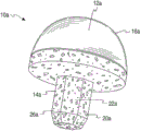
Fig. 1 is the perspective view of an embodiment of implant of the present disclosure;
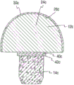
Fig. 2 is the cutaway view of the implant of Fig. 1;
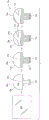
Fig. 3 is the cutaway view of another embodiment of implant of the present disclosure;
Fig. 4 is the front view of the another embodiment of implant of the present disclosure;
Fig. 5 is the cutaway view of the implant of Fig. 4;
Fig. 6 is the cutaway view of the another embodiment of implant of the present disclosure;
Fig. 7 is the cutaway view of the another embodiment of implant of the present disclosure;
Fig. 8 is the cutaway view of the another embodiment of implant of the present disclosure;
Fig. 9 a is the explanatory view of an embodiment of making the method for implant of the present disclosure;
Fig. 9 b is the flow chart that the method shown in Fig. 7 a is shown;
Figure 10 a is the explanatory view of another embodiment of making the method for implant of the present disclosure;
Figure 10 b is the flow chart that the method shown in Fig. 8 a is shown;
Figure 11 a is the explanatory view of another embodiment of making the method for implant of the present disclosure;
Figure 11 b is the flow chart that the method shown in Fig. 9 a is shown;
Figure 12 is the flow chart of an embodiment of making the method for implant of the present disclosure; And
Figure 13 is the flow chart of another embodiment of making the method for implant of the present disclosure.
The specific embodiment
As requested, the specific embodiment of the present invention is disclosed in this; Yet, should be understood that disclosed embodiment only is the example of the present invention that can implement in a variety of forms.Therefore, detail disclosed herein should not be read as restrictive, but only as the foundation of claim, and as representative foundation, differently utilize the present invention with professor those skilled in the art in fact any suitable mode.
In general, prothesis implant body disclosed herein comprises: hinge portion, described hinge portion have RESEARCH OF PYROCARBON supporting or hinged surface; With with the combination of described hinge portion or otherwise grow or outgrowth fixed structure or part in the related porous skeleton.RESEARCH OF PYROCARBON is and skeleton and the biocompatible fragile material of cartilage.It has good durable and strength characteristics, and is considered to good supporting or articulate material for joint repair and displacement application.The area supported of implant for example can be articulated in bodily tissue, for example skeleton of nature, perhaps can be articulated in the surface of contiguous prosthesis structure.This implant is particularly useful in osteoarthrosis reparation and displacement, and can be used for treating or repair the defective in for example knee, buttocks, shoulder, finger, elbow, toe or the ankle.Yet, should be appreciated that the use of this implant is not limited to the joint of joint repair or concrete appointment.
See figures.1.and.2, implant 10a comprises: first or hinge portion 12a, it is related with second portion or skeletal fixation part 14a.In the illustrated embodiment, skeletal fixation part 14a is configured as in the section of the skeleton that can be received or be implanted to the joint position place, and comprises growth or outgrowth structure or zone in the porous skeleton.Hinge portion 12a also comprises area supported 16a, and described area supported 16a is made of RESEARCH OF PYROCARBON, and serves as the hinged or area supported of implant 10a.In the illustrated embodiment, skin or the covering of area supported 16a formation hinge portion 12a more specifically fully cover matrix or substrate 24a(sees Fig. 2).Yet, should be appreciated that the size of area supported 16a can be chosen to only cover a part or a plurality of part of substrate 24a according to the pin joint of the expectation of implant.Alternatively, whole hinge portion 12a can be formed by RESEARCH OF PYROCARBON.
At Fig. 1 and Fig. 2 and in the embodiment shown in other accompanying drawings that this comprises, hinge portion 12a is hemispherical or sphere.In this configuration, hinge portion 12a for example can serve as articulated joint or the hinged ball that sees the ball-and-socket joint in buttocks or the shoulder usually.Yet the hinge portion 12a of this embodiment described here and other embodiment can be designed to other functions of joint, for the joint of other types or even for other bone surgery application scenarios.Therefore, according to the application scenario, hinge portion 12a can present various suitable sizes and the geometry of regular and irregular.For example, hinge portion can be cuboidal, columniform, cup-shaped etc.In addition, according to the application scenario of expectation, area supported 16a can present various configurations, for example spill.
Second or skeletal fixation part 14a preferably include loose structure or regional 26a, to allow growth or outgrowth in the skeleton.In one embodiment, skeletal fixation part 14a can be made of porous materials fully or partly, or is made for and comprises hole, surface holes 20a more specifically.In addition, skeletal fixation part 14a comprises that size is selected to and is configured as protuberance or the handle element 22a that can implant in the skeleton.In the illustrated embodiment, handle element 22a has polygon cross section, particularly hexagonal cross-section.In other embodiments, can to have other polygonal shapes maybe can be cylindrical, spherical, conical or any other suitable configuration to handle element 22a.In a further embodiment, can form a plurality of protuberances or handle element 22a, to help the rotation of restriction implant or different skeletal fixation structures is provided.
In the time of in implanting skeleton, skeletal fixation part 14a, the particularly loose structure of handle element 22a or the outer and/or interior growth that regional 26a is easy to osteocyte and tissue, thereby strengthened implant 10a fixing to skeleton.The porous zone of the skeletal fixation part of the porous of skeletal fixation part 14a zone 26a and other embodiment described here can have promote osseous tissue outer and/or in grow into hole dimension, hole interconnectivity and/or other architectural features in the hole, as known in the art.Preferably, skeletal fixation part 14a is entirely by highly porous material or be suitable for being adjusted into porous materials and form, and the porosity that described material has can be low to moderate about percent by volume of 55,65 or 75 or high to about percent by volume of 80,85 or 90.Yet, should be appreciated that skeletal fixation part 14a can entirely not constructed by porous material, but comprise a zone or a plurality of zone that is constituted by location porous material thereon.
With reference to Fig. 2, in this embodiment, implant 10a has core 18a, and described core 18a comprises: porous section or the regional 26a of the main body of hinge portion 12a or substrate 24a and skeletal fixation part 14a.In one embodiment, thus core 18a substrate 24a and porous zone 26a can be by homogenous material for example carbon, particularly fine and close isotropic graphite structure.Similarly, substrate 24a and porous handle element 22a can be single-piece or integral body or integral type structure.
In order to strengthen implant or its part visibility under fluoroscopic examination or x radial imaging, carbon can be mixed with or otherwise comprise any suitable ray saturating material, for example tungsten, zirconium oxide or barium sulfate.Among the embodiment, substrate 24a comprises outer surface 28a shown in figure 2, and described outer surface 28a has location pyrolytic carbon layer 30a thereon at least in part.Pyrolytic carbon layer 30a helps to form the area supported 16a of hinge portion 12a.Should be appreciated that core 18a also can be constructed by any other suitable material that can apply RESEARCH OF PYROCARBON in the above and be suitable in the bone surgery application scenario.
The 14a of skeletal fixation part again, in this embodiment, skeletal fixation part 14a comprises the porous zone 26a of core 18a.As explained in more detail below, the porous of core 18a zone 26a can form in the following manner: with hole or the hole drill hole of hole or hole 20a or array or be machined to and/or pass porous zone 26a.Then, hole or the hole 20a of the porous of formation zone 26a can be soaked into and be coated with coating, for example metal coating, to promote growth or outgrowth in the skeleton, as explained in more detail below.In one embodiment, hole 20a spreads all over whole skeletal fixation part 14a.In other embodiments, hole 20a is formed on the porous zone, described porous zone from outer surface extend about 500um to 4000um, preferably approximately 1000um to 2000um goes forward side by side into skeleton standing part 14a.Alternatively, at as described in Fig. 7 and Fig. 8, porous zone 26a can be by the material structure of the porosity with expectation and attached or put on core as following.
The explanatory view of an embodiment of the method for the implant 10a shown in shop drawings 1 and Fig. 2 and flow chart are respectively shown in Fig. 9 a and Fig. 9 b.Should be understood that the step of described method can be carried out with any suitable order of implant that formation meets the bone surgery purposes of its expectation.In a step, carbon 32a, a preferably fine and close isotropic graphite are machined or otherwise are processed into the shape of expectation, to form the core 18a of implant 10a.In the illustrated embodiment, piece 32a is machined to the core 18a with substrate 24a and skeletal fixation part 14a.Substrate 24a forms hinge portion 12a at least in part.Then, the hole of hole or hole 20a or array or hole form in the skeletal fixation part 14a of core 18a, thereby form the porous zone 26a of skeletal fixation part 14a.In one embodiment, skeletal fixation part 14a is holed or otherwise machined, to form hole 20a in the 26a of porous zone.
In another step, skeletal fixation part 14a is by shade or otherwise protection or covering, and the substrate 24a of the core 18a that stays exposes, and pyrolytic carbon layer 30a is applied in the outer surface 28a of substrate 24a.Pyrolytic carbon layer 30a can apply by any suitable process.In one embodiment, pyrolytic carbon layer 30a applies by CVD.In another step, hinge portion 12a/ substrate 24a is by shade or otherwise protection or covering, the skeletal fixation part 14a that stays, particularly porous zone 26a expose, and coating is applied at least a portion of porous zone 26a, makes coating soak into hole 20a and applies the porous zone 26a of second portion 14a.In one embodiment, coating be metal, such as but not limited to tantalum, titanium, niobium, their alloy or any other suitable metal or alloy.In addition, metal for example can put on porous zone 26a by CVD, PVD or any other suitable process.Other examples of coating comprise that skeleton outgrowth or interior growth coating, for example hydroxyapatite or calcium phosphate form thing.
The implant 10a that forms comprises: the hinged or 12a of first, and it comprises RESEARCH OF PYROCARBON area supported 16a; With second or skeletal fixation part 14a, it has and is suitable for osteocyte and tissue is outer and/or loose structure or the regional 26a of interior growth.
Fig. 3 shows another embodiment of implant 10b of the present disclosure, and it comprises hinged or the 12b of first and second or skeletal fixation part 14b with porous zone 26b.Similar with previous embodiment, above comprising, hinge portion 12b has main body or the substrate 24b of pyrolytic carbon layer 30b, and described pyrolytic carbon layer 30b forms area supported 16b.Substrate 24b can be by being fit to apply any material of RESEARCH OF PYROCARBON thereon or the combination of material is made, and in one embodiment, and substrate 24b is carbon, fine and close isotropic graphite preferably.Additionally, in order to strengthen implant or its part visibility under fluoroscopic examination or x radial imaging, carbon can be mixed with or otherwise comprise any suitable ray saturating material, for example tungsten, zirconium oxide and barium sulfate.
In this embodiment, skeletal fixation part 14b comprises preferred loose structure by metal construction.Skeletal fixation part 14b is individually formed, and does not become whole with substrate 24b.Skeletal fixation part 14b can be by any suitable porous skeleton known in the art outer or interior growing metal structure make.For example, skeletal fixation part 14b can be by usually can be by Zimmer, and Inc.(is positioned at the Warsaw of the state of Indiana) the Trabecular Metal that provides
@Make.This material can be disclosed in U.S. Patent No. 5,282,861 mode is formed by netted vitreous body carbon foam substrate by the CVD process, and described substrate is soaked into and is coated with metal, for example tantalum, titanium, niobium, their alloy or any other suitable metal or alloy.Porous metal structure can have hole dimension, hole interconnectivity and/or other architectural features that promotes osseous tissue outgrowth and/or interior growth.
As described in more detail below, skeletal fixation part 14b is bonding or otherwise be attached to the substrate 24b of hinge portion 12b by metal sandwich 34b and/or metal outer 36b.Metal sandwich 34b can be deposition or the lip-deep metal level that otherwise places substrate 24b, maybe can be sheet or the paper tinsel that is positioned between substrate 24b and the skeletal fixation part 14b.Preferably, metal sandwich 34b is constructed by the metal or alloy identical with the metal or alloy of skeletal fixation part 14 with metal outer 36b.The thickness that should be pointed out that metal sandwich 34b and metal outer 36b does not draw in the accompanying drawings in proportion, but for showing that purpose is strengthened.The thickness of this interlayer 34b can be at about 100um between about 1mm, more preferably approximately between the extremely about 600um of 400um.The thickness of skin 36b can be at about 50um between about 400um, more preferably approximately between the extremely about 250um of 150um.Yet, should be appreciated that the implant characteristic in order to obtain to expect, described thickness can be changed.
The explanatory view of an embodiment of the method for making implant 10b and flow chart are shown respectively shown in Figure 10 a and Figure 10 b.Should be understood that the step of described method can be made any suitable order of the implant that is suitable in the bone surgery application scenario and carry out.Carbon 32b, preferably fine and close isotropic or fibre-reinforced graphite are machined or otherwise processing, with the substrate 24b of the hinge portion 12b that forms implant 10b.In order to form area supported 16b, pyrolytic carbon layer 30b is applied in the outer surface 28b of substrate 24b by any suitable method as known in the art.For example, pyrolytic carbon layer can apply by CVD.
By porous metal structure, preferably the skeletal fixation part 14b that constitutes of porous tantalum structure places against metal sandwich 34b.Metal outer 36b, preferably the tantalum metal outer is applied in skeletal fixation part 14b, metal sandwich 34b and substrate 24b/ hinge portion 12b.Similarly, substrate 24b can comprise and recessedly cuts portion, hole or other wrong partially portions, thereby when outer 36b was applied in, metal can engage and enter this recessed portion, hole or other the wrong partially portions of cutting in the surface, to provide mechanical interlocked.Preferably but and optionally, interlayer 34b, outer 36b and skeletal fixation part 14b are all by identical metal construction.After outer 36b had been applied in, metal sandwich 34b, metal outer 36b and skeletal fixation part 14b stood high temperature, so that skeletal fixation part 14b is adhered to substrate 24b and forms implant 10b.
Fig. 4 and Fig. 5 show another embodiment of implant 10c of the present disclosure.Similar with other embodiment, implant 10c comprises hinged or the 12c of first and skeletal fixation or second portion 14c.With reference to Fig. 5, hinge portion 12c comprises main body or substrate 24c.Substrate 24c comprises surperficial 28c, is positioned with pyrolytic carbon layer 30c on the described surperficial 28c.Substrate 24c can be by being fit to apply any material of RESEARCH OF PYROCARBON thereon or the combination of material is made, and in one embodiment, and substrate 24c is carbon, fine and close isotropic or fibre-reinforced graphite preferably.Additionally, in order to strengthen implant or its part visibility under fluoroscopic examination or x radial imaging, carbon can be mixed with or otherwise comprise any suitable ray saturating material, for example tungsten, zirconium oxide or barium sulfate.
In another embodiment, as shown in Figure 6, implant 10c can comprise the interlayer 40c of deposition and thin interlayer, and described thin interlayer for example is to be positioned between skeletal fixation part 14c and the substrate 24c to assist metal forming or the sheet 42c of adhesion process.The thickness that should be pointed out that metal sandwich 40c and metal forming 42c does not draw in the accompanying drawings in proportion, but for showing that purpose is strengthened.The thickness of interlayer 40c can be at about 100um between about 1000um, more preferably approximately between the extremely about 600um of 400um.The thickness of paper tinsel or sheet 42c can be at about 100um between about 1000um, more preferably approximately between the extremely about 600um of 400um.
The explanatory view of an embodiment of method of implant 10c shown in shop drawings 5 and Fig. 6 and flow chart are shown respectively shown in Figure 11 a and Figure 11 b.The step of method described here can be made any order of the implant that is suitable in the bone surgery application scenario and carry out.Carbon 32c, preferably fine and close isotropic graphite are machined or otherwise processing, with the substrate 24c of the hinge portion 12c that forms implant.Pyrolytic carbon layer 30c is applied in the outer surface 28c of substrate 24c.Preferably by easily and the metal sandwich 40c that constitutes of the metal that dissolves each other of the metal of porous metals second portion 14c be applied in the surperficial 38c of substrate 24c.In one embodiment, metal sandwich is made of titanium.Metal sandwich 40c can apply by any suitable process as known in the art, for example CDV.Recessed portion, hole and/or other the wrong partially portions in surface of cutting can be arranged in substrate 24c, particularly surperficial 38c, thereby when metal sandwich 40c is applied in substrate 24c, metal enters and engage described recessed portion, the hole etc. of cutting, and is mechanical interlocked to form between metal sandwich 40c and substrate 24c.In another embodiment, interlayer 40c is metal forming or sheet.
By porous metal structure, for example the skeletal fixation part 14c that constitutes of any porous metal structure described here or as known in the art places against metal sandwich 40c, to form assembly.In one embodiment, one among porous skeletal fixation part 14c and the interlayer 40c is made of tantalum, and another is made of titanium.Alternatively, interlayer, for example metal forming or sheet (not shown) can be placed between the metal sandwich 34c of porous metals skeletal fixation part 14c and deposition, thereby implant comprises metal sandwich 40c and metal forming or the sheet of deposition.In one embodiment, metal forming or sheet and interlayer 34c are by identical metal construction.
Heat and pressure are applied in described assembly and continue sufficiently long a period of time, to cause solid-state diffusion between interlayer 40c and porous metals skeletal fixation part 14c and (if using) metal forming or sheet.As is known to persons skilled in the art, solid-state diffusion is movement and the transfer of the atom in the solid phase.Solid-state diffusion is bonding form to be connected in the following manner: since atom between two or more metal surfaces transfer and under atom level, form bonding.Heat and pressure can put on described assembly by the whole bag of tricks as known in the art.For example, can heat described assembly by electric power, radiation, optics, induction, burning, microwave or any other suitable method as known in the art.As known in the art, can before put into stove at described assembly, described assembly be clamped together and mechanically exert pressure, maybe can exert pressure by the hot-pressing system that can when described assembly reaches target temperature, exert pressure.In addition, hot pressing can comprise in this area also known high temperature insostatic pressing (HIP).In one embodiment, described assembly in a vacuum or be held and be heated to about at least 940 ℃ and continue 4 hours under the pressure below atmospheric pressure of another inert atmosphere.
Preferably, the assembly that is held is heated to the fusion temperature that is lower than member.Forming the bonding required time may be as short as less than 1 hour and grows to about 48 hours, and this depends on related metal, temperature, atmosphere and applied pressure.Implant forms after diffusion process is finished.
The another embodiment of implant 10d of the present disclosure is shown in Figure 7.Implant 10d comprises core 18d, and described core 18d limits for the substrate 24d of hinge portion 12d and is used for the substrate 25d of skeletal fixation part 14d.Similar with other embodiment disclosed herein, have the pyrolytic carbon layer 30d that forms area supported 16d on the substrate 24d of hinge portion 12d.Core 18d can be by being fit to apply any material of RESEARCH OF PYROCARBON thereon or the combination of material is made, and in one embodiment, and substrate 24d is carbon, fine and close isotropic graphite preferably.Additionally, in order to strengthen implant or its part visibility under fluoroscopic examination or x radial imaging, carbon can be mixed with or otherwise comprise any suitable ray saturating material, for example tungsten.
Figure 12 is the flow chart of an embodiment that the method for the implant 10d shown in the shop drawings 7 is shown.Any order of the implant of the step of method described here shown in can shop drawings 7 is carried out.In a step, carbon, a preferably fine and close isotropic graphite are machined or otherwise processing, have the core 18d of substrate 24d and substrate 25d with formation.In another step, pyrolytic carbon layer 30d is applied in the outer surface 28d of the substrate 24d of hinge portion 12d.Preferably the intermediate layer 44d that is made of the metal that can adhere to graphite base 24e preferably is applied to the outer surface of the substrate 25d of skeletal fixation part 14d by CVD or PVD.Porous outer layer 46d preferably puts on intermediate layer 44d by plasma spraying.Yet, should be appreciated that and can use any other suitable method that outer 46d is attached to intermediate layer 44d or directly be attached to substrate 25d when being omitted in the intermediate layer.In order to obtain roughly smooth hinged surface, the area supported 16d of pyrolytic carbon layer 30d can be polished or be done other processing or finishing.
Forward Fig. 8 to, implant 10e is another embodiment of bone surgery device of the present disclosure, and with disclosed other implants are similar herein.Implant 10e comprises the core 18e of metal (such as but not limited to titanium or tungsten), and described core 18e partly limits hinge portion 12e and skeletal fixation part 14e.Has the pyrolytic carbon layer 30e that forms area supported 16e on the hinge portion 12e.Intermediate layer 19e is positioned between pyrolytic carbon layer 30e and the core 18e.Preferably by carbon for example, the material structure of fine and close isotropic graphite preferably, described material can bonding or otherwise adhere to metal core 18e and pyrolytic carbon layer 30e to intermediate layer 19e.Core 18e also forms the interior section of skeletal fixation part 14e, and is surrounded by the porous outer layer 46e that forms porous zone 26e at least in part.In the illustrated embodiment, outer 46e is by metal, make such as but not limited to POROUS TITANIUM or tantalum metal structure.In one embodiment, outer 46e is usually can be by Zimmer, and Inc.(is positioned at the Warsaw of the state of Indiana) the Trabecular Metal that provides
@Make.Yet, should be appreciated that feature according to the expectation of implant can be outer 46e and uses other materials.Outer 46e/ porous zone 26e preferably has outside the promotion osseous tissue and/or thickness, hole dimension, hole seriality and/or other architectural features of interior growth.
Figure 13 is the flow chart of an embodiment that the method for the implant 10e shown in the shop drawings 8 is shown.Any order of the implant of the step of method described here shown in can shop drawings 8 is carried out.In a step, the metal core uses metal, forms the shape of expectation such as but not limited to titanium or tungsten.In another step, carbon, a preferably fine and close isotropic graphite are machined or otherwise processing, to form intermediate layer 19e.Core 18e and intermediate layer 19e locate located adjacent one anotherly.Heat and pressure are applied in described assembly and continue sufficiently long a period of time, to cause solid-state diffusion between core 18e and intermediate layer 19e.In another step, pyrolytic carbon layer 30e is applied in the outer surface 28e of intermediate layer 19e.In order to obtain roughly smooth hinged surface, the area supported 16e of pyrolytic carbon layer 30e can be polished or be done other processing or finishing.Outer 46e is applied in the core 18e of skeletal fixation part 14e, to form porous zone 26e.Outer 46e is preferably by constituting with the metal of the material adhesion of core 18e.In one embodiment, the outer 46e that is made of metal, for example titanium preferably puts on core 18e by plasma spraying.Alternatively, outer 46e can by the porous tantalum metal structure, for example usually can be by Zimmer, Inc.(is positioned at the Warsaw of the state of Indiana) the Trabecular Metal that provides
@Constitute.In this embodiment, but metal outer 46e adjacent core 18e location.Heat and pressure are applied in described assembly and continue sufficiently long a period of time, to cause solid-state diffusion between metal outer 46e and core 18e.Should be appreciated that core 18e and intermediate layer 19e bonding and outer 46e each other can form to the bonding of core 18e in single step or two step process.
Should be understood that said method, constituent, device and embodiment are that the application for the principle of theme disclosed herein explains.It is to be further understood that some modification can be made by those skilled in the art under the situation of the spirit and scope that do not deviate from disclosed herein and/or the theme that requires.Therefore, scope of the present invention is not limited to above description, but proposes in the claims and/or in the claim in any future of making in any application that requires priority of the present disclosure.
Claims (23)
1. bone surgery implant comprises:
Hinge portion with RESEARCH OF PYROCARBON area supported; And
The skeletal fixation part, described skeletal fixation part is extended from hinge portion, and has the loose structure that is configured to growth in skeleton outgrowth or the skeleton.
2. implant as claimed in claim 1 is characterized in that, described hinge portion also comprises substrate, and described skeletal fixation partly is attached to described substrate.
3. implant as claimed in claim 2 is characterized in that, described implant also comprises at least part of metal sandwich between described skeletal fixation part and described substrate.
4. implant as claimed in claim 3 is characterized in that, described metal sandwich is made of identical metal material with described skeletal fixation part.
5. implant as claimed in claim 3 is characterized in that, described interlayer is made of first metal, and described skeletal fixation part is made of second metal, and described first metal can dissolve each other with described second metal.
6. implant as claimed in claim 3, it is characterized in that, described implant also comprises the metal outer that covers described skeletal fixation part and described interlayer at least in part, and wherein, described interlayer and metal outer partly are attached to described substrate with described skeletal fixation.
7. implant as claimed in claim 1 is characterized in that, described skeletal fixation part is made of porous tantalum.
8. implant as claimed in claim 2 is characterized in that, described substrate is made of isotropic graphite.
9. method that forms the bone surgery implant comprises:
Carbon spare with hinge portion and skeletal fixation part is provided, and described skeletal fixation partly has the porous zone;
One deck RESEARCH OF PYROCARBON is applied on the outer surface of hinge portion;
Metal coating is put on the described porous zone of described skeletal fixation part.
10. method as claimed in claim 9 is characterized in that, described metal coating is selected from the group of being made up of tantalum, titanium, niobium or their alloy or chemical compound.
11. method as claimed in claim 9 is characterized in that, described RESEARCH OF PYROCARBON applies by chemical vapour deposition (CVD).
12. a method that forms the bone surgery implant comprises:
Substrate with first surface and second surface is provided;
One deck RESEARCH OF PYROCARBON is put on the described first surface of described substrate;
The interlayer that will comprise metal is placed between the described second surface and porous metal structure of described substrate; And
Described porous metal structure and described substrate are combined, to form the bone surgery implant.
13. method as claimed in claim 12 is characterized in that, described combination comprises: with heat with pressure puts on substrate, interlayer and porous metal structure and make the persistent period be long enough to realize solid-state diffusion between described interlayer and described porous metal structure.
14. method as claimed in claim 12 is characterized in that, one in described porous metal structure and the described interlayer is made of tantalum, and another is made of titanium.
15. method as claimed in claim 12 is characterized in that, described interlayer puts on the described second surface of described substrate by chemical vapour deposition (CVD).
16. method as claimed in claim 12 is characterized in that, described RESEARCH OF PYROCARBON applies by chemical vapour deposition (CVD).
17. a method that forms the bone surgery implant comprises:
One deck RESEARCH OF PYROCARBON is put on the first surface of substrate;
Metal sandwich is put on the second surface of described substrate;
Porous metal structure is contacted with described metal sandwich; And
Second metal outer is put on described substrate, described interlayer and described porous metal structure.
18. method as claimed in claim 17 is characterized in that, described metal sandwich, described metal outer and described porous metal structure all comprise identical metal.
19. method as claimed in claim 18 is characterized in that, described metal is selected from the group of being made up of tantalum, titanium, niobium or their alloy or chemical compound.
20. method as claimed in claim 17 is characterized in that, described RESEARCH OF PYROCARBON puts on described substrate by chemical vapour deposition (CVD).
21. method as claimed in claim 17 is characterized in that, described metal sandwich puts on described substrate by chemical vapour deposition (CVD).
22. method as claimed in claim 17 is characterized in that, described metal outer applies by chemical vapour deposition (CVD).
23. a method that forms the bone surgery implant comprises:
One deck RESEARCH OF PYROCARBON is put on the first surface of substrate;
To be put on the second surface of described substrate by the interlayer that metal constitutes;
Porous metal structure is provided;
Metal forming is placed between described interlayer and the described porous metal structure; And
Make described porous metal structure, described metal forming and described interlayer diffusion combination.
Applications Claiming Priority (3)
| Application Number | Priority Date | Filing Date | Title |
|---|---|---|---|
| US38767810P | 2010-09-29 | 2010-09-29 | |
| US61/387,678 | 2010-09-29 | ||
| PCT/US2011/053492 WO2012050837A1 (en) | 2010-09-29 | 2011-09-27 | Pyrolytic carbon implants with porous fixation component and methods of making the same |
Publications (1)
| Publication Number | Publication Date |
|---|---|
| CN103189018A true CN103189018A (en) | 2013-07-03 |
Family
ID=44860506
Family Applications (1)
| Application Number | Title | Priority Date | Filing Date |
|---|---|---|---|
| CN2011800526488A Pending CN103189018A (en) | 2010-09-29 | 2011-09-27 | Pyrolytic carbon implants with porous fixation component and methods of making the same |
Country Status (6)
| Country | Link |
|---|---|
| US (2) | US20120101592A1 (en) |
| EP (1) | EP2621410A1 (en) |
| CN (1) | CN103189018A (en) |
| AU (1) | AU2011314157A1 (en) |
| CA (1) | CA2812933A1 (en) |
| WO (1) | WO2012050837A1 (en) |
Cited By (2)
| Publication number | Priority date | Publication date | Assignee | Title |
|---|---|---|---|---|
| CN105105875A (en) * | 2015-08-04 | 2015-12-02 | 西安交通大学 | Biomimetic artificial hip joint with internal growth function |
| CN110870812A (en) * | 2018-08-29 | 2020-03-10 | 捷迈有限公司 | Metatarsophalangeal joint replacement device and method |
Families Citing this family (21)
| Publication number | Priority date | Publication date | Assignee | Title |
|---|---|---|---|---|
| US7892288B2 (en) | 2001-08-27 | 2011-02-22 | Zimmer Technology, Inc. | Femoral augments for use with knee joint prosthesis |
| US20040162619A1 (en) | 2001-08-27 | 2004-08-19 | Zimmer Technology, Inc. | Tibial augments for use with knee joint prostheses, method of implanting the tibial augment, and associated tools |
| US20030065397A1 (en) | 2001-08-27 | 2003-04-03 | Hanssen Arlen D. | Prosthetic implant support structure |
| IT1398443B1 (en) * | 2010-02-26 | 2013-02-22 | Lima Lto S P A Ora Limacorporate Spa | INTEGRATED PROSTHETIC ELEMENT |
| WO2012050837A1 (en) | 2010-09-29 | 2012-04-19 | Zimmer, Inc. | Pyrolytic carbon implants with porous fixation component and methods of making the same |
| US20140088716A1 (en) * | 2012-09-21 | 2014-03-27 | Zimmer, Inc. | Variable density implant and method |
| ITMI20132154A1 (en) * | 2013-12-20 | 2015-06-21 | Adler Ortho S R L | FEMORAL COMPONENT FOR KNEE PROSTHESIS. |
| RU2016144388A (en) * | 2014-04-14 | 2018-05-18 | Керамтек Гмбх | SURFACE ENDOPROTHESIS FOR NATURAL FEMORAL HEAD |
| ES2552703B1 (en) * | 2014-05-30 | 2016-10-07 | Universidad Pública de Navarra | Measurement sensor of the distribution of physical quantities in an optical fiber and associated measurement procedure |
| CN106470644A (en) * | 2014-07-09 | 2017-03-01 | 陶瓷技术有限责任公司 | The face instead prosthese of the full pottery of the medial surface with porous |
| US10182917B2 (en) * | 2016-04-11 | 2019-01-22 | Arthrex, Inc. | Components for artificial joints |
| RU167669U1 (en) * | 2016-06-07 | 2017-01-10 | Олег Викторович Барзинский | IMPLANT FOR SURGICAL REPLACEMENT OF BONE DEFECTS |
| EP3287150B1 (en) * | 2016-08-22 | 2022-12-14 | WALDEMAR LINK GmbH & Co. KG | Coating for an implant |
| EP3570787B1 (en) | 2017-01-20 | 2022-05-04 | Biomet Manufacturing, LLC | Modular augment component |
| US10772731B2 (en) * | 2017-04-14 | 2020-09-15 | Smed-Ta/Td, Llc | Orthopaedic implant with bonded porous material |
| RU178565U1 (en) * | 2017-09-18 | 2018-04-11 | Федеральное государственное бюджетное образовательное учреждение высшего образования "Самарский государственный медицинский университет" Министерства здравоохранения Российской Федерации | Joint Endoprosthesis Element |
| DE102018218498A1 (en) * | 2018-10-29 | 2020-04-30 | Aesculap Ag | Implant, preferably for treating a bone and / or cartilage defect |
| USD948052S1 (en) * | 2019-10-07 | 2022-04-05 | L&K Biomed Co., Ltd. | Part of spinal fusion cage |
| WO2021150490A1 (en) * | 2020-01-20 | 2021-07-29 | Biopoly, Llc | A toe implant, related kit, surgical method, and method of manufacturing |
| USD945620S1 (en) | 2020-01-29 | 2022-03-08 | Biopoly, Llc | Great toe implant |
| EP4167909A1 (en) * | 2020-06-18 | 2023-04-26 | Encore Medical, L.P. dba DJO Surgical | Intramedullary canal sparing humeral implant and related methods |
Citations (10)
| Publication number | Priority date | Publication date | Assignee | Title |
|---|---|---|---|---|
| US3707006A (en) * | 1970-08-26 | 1972-12-26 | Gulf Oil Corp | Orthopedic device for repair or replacement of bone |
| EP0001147A1 (en) * | 1977-09-08 | 1979-03-21 | CarboMedics, Inc. | Joint prosthesis element |
| US5198308A (en) * | 1990-12-21 | 1993-03-30 | Zimmer, Inc. | Titanium porous surface bonded to a cobalt-based alloy substrate in an orthopaedic implant device |
| EP0560279A1 (en) * | 1992-03-11 | 1993-09-15 | Ultramet | Open cell tantalum structures for cancellous bone implants and cell and tissue receptors |
| US6436146B1 (en) * | 1997-12-10 | 2002-08-20 | Bioprofile | Implant for treating ailments of a joint or a bone |
| CN1416330A (en) * | 2000-01-30 | 2003-05-07 | 岱密克龙有限公司 | Component for prosthetic joint having diamond load bearing and articulation surface |
| US20070225822A1 (en) * | 2005-12-09 | 2007-09-27 | Santilli Albert N | Orthopedic Implants Coated with Pyrolytic Carbon |
| CN101198724A (en) * | 2005-06-15 | 2008-06-11 | 丹福斯有限公司 | A corrosion resistant object having an outer layer of a precious metal |
| US20090098310A1 (en) * | 2007-10-10 | 2009-04-16 | Zimmer, Inc. | Method for bonding a tantalum structure to a cobalt-alloy substrate |
| US20090240336A1 (en) * | 2006-03-22 | 2009-09-24 | Ascension Orthopedics, Inc. | Prosthetic implant and assembly method |
Family Cites Families (44)
| Publication number | Priority date | Publication date | Assignee | Title |
|---|---|---|---|---|
| GB1165698A (en) | 1965-11-05 | 1969-10-01 | Guinness De Laszlo M A P Henry | Improvements in or relating to Prostheses |
| US3623164A (en) | 1969-10-06 | 1971-11-30 | Gulf Oil Corp | Prosthetic device |
| US3893196A (en) | 1970-08-06 | 1975-07-08 | Robert F Hochman | Body implant material |
| US3926567A (en) | 1973-04-05 | 1975-12-16 | Nasa | Cermet composition and method of fabrication |
| US4012796A (en) | 1975-09-24 | 1977-03-22 | Howmedica, Inc. | Interpositioning collar for prosthetic bone insert |
| US4126924A (en) | 1977-02-07 | 1978-11-28 | General Atomic Company | Socket and joint prostheses |
| DE3169607D1 (en) | 1980-12-29 | 1985-05-02 | Carbomedics Inc | Method of making all-pyrocarbon prosthetic device components |
| JPS57134154A (en) | 1981-02-12 | 1982-08-19 | Otani Sugirou | Carbonacious artificial filler and prosthetic material and production thereof |
| FR2566272B1 (en) | 1984-06-20 | 1987-04-03 | France Implant Est | IMPROVED SURGICAL IMPLANTS WITH COATING, ESPECIALLY TITANIUM NITRIDE |
| KR960005871B1 (en) | 1986-05-15 | 1996-05-03 | 스미또모 시멘트 가부시끼가이샤 | Artificial biocompatible material |
| US4846834A (en) | 1986-05-27 | 1989-07-11 | Clemson University | Method for promoting tissue adhesion to soft tissue implants |
| US4718905A (en) | 1986-08-13 | 1988-01-12 | Freeman Jerre M | Haptic element using ion beam implantation for an intraocular lens |
| DE4009337A1 (en) | 1990-03-23 | 1991-09-26 | Repenning Detlev | METHOD FOR PRODUCING OSTEO-INTEGRATING SURFACES ON SKELETON IMPLANTS AND SKELETON IMPLANT |
| DE19517843B4 (en) | 1995-05-18 | 2007-07-05 | Hörmansdörfer, Gerd | Elastic ball head for hip joint implants |
| US5593445A (en) * | 1995-03-24 | 1997-01-14 | Waits; C. Thomas | Bi-axial prosthetic joint |
| US5534033A (en) | 1995-06-05 | 1996-07-09 | Carbomedics, Inc. | Orthopedic prosthetic implants with pyrolytic carbon or ceramic articulating surfaces |
| US5671322A (en) * | 1996-01-17 | 1997-09-23 | Advanced Ceramics Corporation | Lateral flash evaporator |
| US5981827A (en) | 1996-11-12 | 1999-11-09 | Regents Of The University Of California | Carbon based prosthetic devices |
| US6217616B1 (en) | 1998-09-09 | 2001-04-17 | Ascension Orthopedics, Inc. | Elbow prosthesis |
| US7632309B1 (en) | 1999-12-13 | 2009-12-15 | St. Jude Medical, Inc. | Pyrolytic carbon and metal/metalloid carbide composites |
| FR2833156B1 (en) | 2001-12-12 | 2004-10-15 | Bioprofile | TRAPEZIAN OR TRAPEZO-METACARPIAN IMPLANT |
| AU2003279231A1 (en) * | 2002-06-21 | 2004-01-06 | Medical Carbon Research Institute | Bone and tissue implants and method of making |
| US7641696B2 (en) | 2003-01-07 | 2010-01-05 | Ascension Orthopedics, Inc. | Carpometacarpal joint prosthesis |
| EP1643945B1 (en) | 2003-04-18 | 2012-12-05 | Ascension Orthopedics, Inc. | Interpositional biarticular disk implant |
| US20050171604A1 (en) | 2004-01-20 | 2005-08-04 | Alexander Michalow | Unicondylar knee implant |
| US20070156250A1 (en) | 2005-12-09 | 2007-07-05 | Seitz William H Jr | Orthopedic Implants Coated with Pyrolytic Carbon |
| FR2903157B1 (en) | 2006-06-29 | 2009-10-30 | Bioprofile Sa | ASSEMBLY OF A PIECE OF PYROCARBON AND ANOTHER PIECE |
| EP2086471B1 (en) | 2006-11-29 | 2010-11-03 | Ascension Orthopedics, Inc. | Shoulder joint implant |
| WO2008090468A2 (en) | 2007-01-22 | 2008-07-31 | Zimmer, Gmbh | An implant and a method for partial replacement of joint surfaces |
| US8177849B2 (en) | 2007-05-07 | 2012-05-15 | Zimmer, Inc. | Methods and apparatuses for attaching tissue to orthopaedic implants |
| US8979935B2 (en) | 2007-07-31 | 2015-03-17 | Zimmer, Inc. | Joint space interpositional prosthetic device with internal bearing surfaces |
| EP2249887B1 (en) | 2008-01-30 | 2017-06-21 | Zimmer, Inc. | Othopedic component of low stiffness |
| FR2928828B1 (en) | 2008-03-21 | 2010-04-02 | Tornier Sa | CARTILAGE RESURFACING IMPLANT |
| FR2928829B1 (en) | 2008-03-21 | 2011-07-08 | Tornier Sa | JOINT IMPLANT COMPRISING A PYROLYTIC CARBON CONTACT SURFACE AND A FASTENING PART OBTAINED BY OVERMOLDING |
| WO2009115616A1 (en) | 2008-03-21 | 2009-09-24 | Tornier | Pyrolytic carbon implant with adhesive polymer or elastomer layer |
| US20100094292A1 (en) | 2008-10-14 | 2010-04-15 | Zimmer, Inc. | Modular intramedullary nail |
| US8556972B2 (en) | 2009-04-02 | 2013-10-15 | Sevika Holding AG | Monolithic orthopedic implant with an articular finished surface |
| FR2946862B1 (en) | 2009-06-17 | 2011-07-08 | Tornier Sa | GLENOIDAL PROTHETIC COMPONENT AND SET OF AT LEAST TWO OF THESE COMPONENTS. |
| FR2946864B1 (en) | 2009-06-19 | 2011-07-08 | Tornier Sa | TRAPEZO-METACARPIAN JOINT IMPLANT |
| US9549820B2 (en) | 2009-06-25 | 2017-01-24 | Zimmer, Inc. | Glenoid implant with synthetic labrum |
| US8123813B2 (en) | 2009-07-14 | 2012-02-28 | Biomet Manufacturing Corp. | Pyrocarbon orthopedic implant |
| WO2012024266A1 (en) * | 2010-08-18 | 2012-02-23 | Ascension Orthopedics, Inc. | Pyrocarbon coated bone implants |
| WO2012050837A1 (en) | 2010-09-29 | 2012-04-19 | Zimmer, Inc. | Pyrolytic carbon implants with porous fixation component and methods of making the same |
| US20120158139A1 (en) * | 2010-12-17 | 2012-06-21 | Bio2 Technologies, Inc. | Method and Apparatus for a Porous Orthopedic Implant |
-
2011
- 2011-09-27 WO PCT/US2011/053492 patent/WO2012050837A1/en active Application Filing
- 2011-09-27 EP EP11774127.2A patent/EP2621410A1/en not_active Withdrawn
- 2011-09-27 AU AU2011314157A patent/AU2011314157A1/en not_active Abandoned
- 2011-09-27 CN CN2011800526488A patent/CN103189018A/en active Pending
- 2011-09-27 CA CA2812933A patent/CA2812933A1/en not_active Abandoned
- 2011-09-27 US US13/246,544 patent/US20120101592A1/en not_active Abandoned
-
2014
- 2014-03-05 US US14/197,689 patent/US9192476B2/en active Active
Patent Citations (10)
| Publication number | Priority date | Publication date | Assignee | Title |
|---|---|---|---|---|
| US3707006A (en) * | 1970-08-26 | 1972-12-26 | Gulf Oil Corp | Orthopedic device for repair or replacement of bone |
| EP0001147A1 (en) * | 1977-09-08 | 1979-03-21 | CarboMedics, Inc. | Joint prosthesis element |
| US5198308A (en) * | 1990-12-21 | 1993-03-30 | Zimmer, Inc. | Titanium porous surface bonded to a cobalt-based alloy substrate in an orthopaedic implant device |
| EP0560279A1 (en) * | 1992-03-11 | 1993-09-15 | Ultramet | Open cell tantalum structures for cancellous bone implants and cell and tissue receptors |
| US6436146B1 (en) * | 1997-12-10 | 2002-08-20 | Bioprofile | Implant for treating ailments of a joint or a bone |
| CN1416330A (en) * | 2000-01-30 | 2003-05-07 | 岱密克龙有限公司 | Component for prosthetic joint having diamond load bearing and articulation surface |
| CN101198724A (en) * | 2005-06-15 | 2008-06-11 | 丹福斯有限公司 | A corrosion resistant object having an outer layer of a precious metal |
| US20070225822A1 (en) * | 2005-12-09 | 2007-09-27 | Santilli Albert N | Orthopedic Implants Coated with Pyrolytic Carbon |
| US20090240336A1 (en) * | 2006-03-22 | 2009-09-24 | Ascension Orthopedics, Inc. | Prosthetic implant and assembly method |
| US20090098310A1 (en) * | 2007-10-10 | 2009-04-16 | Zimmer, Inc. | Method for bonding a tantalum structure to a cobalt-alloy substrate |
Cited By (5)
| Publication number | Priority date | Publication date | Assignee | Title |
|---|---|---|---|---|
| CN105105875A (en) * | 2015-08-04 | 2015-12-02 | 西安交通大学 | Biomimetic artificial hip joint with internal growth function |
| CN105105875B (en) * | 2015-08-04 | 2018-01-16 | 西安交通大学 | A kind of biomimetic prosthetic hip joint with interior growth function |
| CN110870812A (en) * | 2018-08-29 | 2020-03-10 | 捷迈有限公司 | Metatarsophalangeal joint replacement device and method |
| US11076964B2 (en) | 2018-08-29 | 2021-08-03 | Zimmer, Inc. | Metarsophalangeal joint replacement device and methods |
| US11779467B2 (en) | 2018-08-29 | 2023-10-10 | Zimmer, Inc. | Metarsophalangeal joint replacement device and methods |
Also Published As
| Publication number | Publication date |
|---|---|
| AU2011314157A1 (en) | 2013-05-09 |
| CA2812933A1 (en) | 2012-04-19 |
| US20120101592A1 (en) | 2012-04-26 |
| WO2012050837A1 (en) | 2012-04-19 |
| US20140188244A1 (en) | 2014-07-03 |
| US9192476B2 (en) | 2015-11-24 |
| EP2621410A1 (en) | 2013-08-07 |
Similar Documents
| Publication | Publication Date | Title |
|---|---|---|
| CN103189018A (en) | Pyrolytic carbon implants with porous fixation component and methods of making the same | |
| EP0566427B1 (en) | A prothesis and a method of making the same | |
| EP0760687B1 (en) | A biomaterial and bone implant for bone repair and replacement | |
| Balla et al. | Tantalum—A bioactive metal for implants | |
| US5496372A (en) | Hard tissue prosthesis including porous thin metal sheets | |
| US20100179662A1 (en) | Monoblock ceramic prosthesis devices | |
| US20100174377A1 (en) | Reticulated particle porous coating for medical implant use | |
| US9265612B1 (en) | Hip implant with porous body | |
| JP2003175099A (en) | Acetabular cup and method of producing the same | |
| US10149765B1 (en) | Hip implant with porous body | |
| EP3409241B1 (en) | Customizable augments for acetabular implants | |
| JP2009514576A (en) | Open-hole biocompatible surface layer for implants, method for production and use thereof | |
| CN104411271A (en) | Artificial joint stem, artificial joint stem component, and artificial joint stem manufacturing method | |
| US10258474B2 (en) | Artificial joint cup | |
| US11419725B2 (en) | Implants including a monolithic layer of biocompatible metallic material | |
| US20160128837A1 (en) | Ceramic components for replacing joint surfaces | |
| CN101984939A (en) | Design method of artificial elbow joint prosthesis with tantalum coating | |
| CN201879868U (en) | Tantalum-coated elbow prosthesis | |
| US10687947B2 (en) | Augments and methods for implanting hip prostheses | |
| CN108472409B (en) | Orthopedic implant | |
| CN101474425A (en) | Artificial metal spongy bone and method for producing the same | |
| CN101999949A (en) | Design method for tantalum coating artificial shoulder prosthesis | |
| KR20220060540A (en) | Bone Implants with Coated Porous Structures | |
| JP2005278874A (en) | Artificial joint | |
| JPH01265954A (en) | Substitute bone |
Legal Events
| Date | Code | Title | Description |
|---|---|---|---|
| C06 | Publication | ||
| PB01 | Publication | ||
| C10 | Entry into substantive examination | ||
| SE01 | Entry into force of request for substantive examination | ||
| C02 | Deemed withdrawal of patent application after publication (patent law 2001) | ||
| WD01 | Invention patent application deemed withdrawn after publication |
Application publication date: 20130703 |