CN102573672A - Endoscopic instrument - Google Patents
Endoscopic instrument Download PDFInfo
- Publication number
- CN102573672A CN102573672A CN2010800326218A CN201080032621A CN102573672A CN 102573672 A CN102573672 A CN 102573672A CN 2010800326218 A CN2010800326218 A CN 2010800326218A CN 201080032621 A CN201080032621 A CN 201080032621A CN 102573672 A CN102573672 A CN 102573672A
- Authority
- CN
- China
- Prior art keywords
- far
- scissor blade
- end effector
- tubular element
- control member
- Prior art date
- Legal status (The legal status is an assumption and is not a legal conclusion. Google has not performed a legal analysis and makes no representation as to the accuracy of the status listed.)
- Pending
Links
Images


Classifications
-
- A—HUMAN NECESSITIES
- A61—MEDICAL OR VETERINARY SCIENCE; HYGIENE
- A61B—DIAGNOSIS; SURGERY; IDENTIFICATION
- A61B17/00—Surgical instruments, devices or methods, e.g. tourniquets
- A61B17/32—Surgical cutting instruments
- A61B17/320016—Endoscopic cutting instruments, e.g. arthroscopes, resectoscopes
-
- A—HUMAN NECESSITIES
- A61—MEDICAL OR VETERINARY SCIENCE; HYGIENE
- A61B—DIAGNOSIS; SURGERY; IDENTIFICATION
- A61B17/00—Surgical instruments, devices or methods, e.g. tourniquets
- A61B17/28—Surgical forceps
- A61B17/29—Forceps for use in minimally invasive surgery
- A61B17/295—Forceps for use in minimally invasive surgery combined with cutting implements
-
- A—HUMAN NECESSITIES
- A61—MEDICAL OR VETERINARY SCIENCE; HYGIENE
- A61B—DIAGNOSIS; SURGERY; IDENTIFICATION
- A61B17/00—Surgical instruments, devices or methods, e.g. tourniquets
- A61B17/28—Surgical forceps
- A61B17/29—Forceps for use in minimally invasive surgery
- A61B2017/2926—Details of heads or jaws
- A61B2017/2932—Transmission of forces to jaw members
- A61B2017/2933—Transmission of forces to jaw members camming or guiding means
- A61B2017/2936—Pins in guiding slots
-
- A—HUMAN NECESSITIES
- A61—MEDICAL OR VETERINARY SCIENCE; HYGIENE
- A61B—DIAGNOSIS; SURGERY; IDENTIFICATION
- A61B17/00—Surgical instruments, devices or methods, e.g. tourniquets
- A61B17/32—Surgical cutting instruments
- A61B2017/320064—Surgical cutting instruments with tissue or sample retaining means
Abstract
An endoscopic instrument includes a control wire having a push rod at its distal end and an end effector assembly having first and second effector elements such as scissors blades mounted on a clevis. The effector elements are operated by a cam-pin on the push rod riding in cam-slots defined in the effector elements. According to one aspect of the invention, the effector elements are symmetrically opened even when the push rod is canted relative to the clevis. According to another aspect of the invention, the effector elements can be rotated into a closed configuration that minimizes the distal dimension across the effector elements. In addition, the effector elements, when in the closed configuration, can rotate together to facilitate insertion of the end effector into an entry portion of an endoscope.
Description
Technical field
The present invention relates generally to surgical instruments.More specifically, the present invention relates to insert the soft endoscope scissors apparatus of the inner chamber that passes endoscope.
Background technology
Endoscopy is to utilize endoscope to get into the minimum intrusive mood medical procedure of inside of human body.Endoscope is made up of rigidity or flexible pipe, optical fiber illuminating system and viewing system usually; Wherein optical fiber illuminating system will pass the pipe of endoscope so that illuminate checked organ or object by the light guiding that light source provides; Viewing system is used to collect the image of checked organ or object and is used for image recording upward perhaps is used for image is sent to the external video processor via fibre bundle through pipe at inner CCD device (video-endoscope), so that observe (optical fiber-endoscope).Endoscope can comprise one or more " work " passage (general diameter is 2-4 mm); Said " work " passage has the come-at-able entry port of surgeon, and special medical apparatus and instruments can enter into the service aisle of endoscope and get into the visual field through said entry port.This special apparatus (it can comprise nipper, biopsy forceps, shears etc.) can be used for promptly organizing, being used for the sample tissue of biopsy or independent tissue, and all these are organized all from inside of human body.
Laparoscopy is a kind of minimum intrusive mood surgical technic, in this technology, passes little otch (being generally 0.5-1.5 cm) through rigidity or flexible peritoneoscope and carries out the operation of abdominal part or chest.Usually there is two types peritoneoscope, comprises: the expansion link lens combination, it is connected in video camera (one chip or three-chip type) usually; With digital peritoneoscope, wherein camera arrangements is in laparoscopically end, thereby saved the bar lens combination.The cable system that is connected in light source (halogen or xenon) inserts and to pass surgical port, to illuminate field of operation so that observe.Abdominal part usually by filled carbon dioxide with generation work and observation space.Passing surgical port can be incorporated into special surgical instruments in abdominal part or the chest, so that take live body away and exteriorize (or its fragment) and/or external object from inside of human body.
Be used for endoscope and laparoscopically surgical instruments and generally include the end effector device that the far-end with pipe or coil is adjacent to install.Handle (or other actuation control devices) is installed on the near-end of pipe or coil, and actuator shaft is managed or coil to moving through.The far-end of actuator changes into the end effector device of expectation with the axially-movable with actuator the mode of motion mechanically is connected in the end effector device.This special endoscope and laparoscopic surgical instrument are referred to as endoscopic surgical instrument or endoscopic instrument at this, and one or more endoscope and one or more peritoneoscope are referred to as endoscope at this.These rules are applicable to most endoscopic instrument; But because apparatus generally is to design to certain applications; So concrete endoscopic instrument is different aspect length, size, hardness and other characteristics; This is because these apparatuses can be used in multiple minimum intrusive mood surgical procedure, comprises the endoscope and the laparoscopic use of above general introduction.
Summary of the invention
The present invention provides a kind of endoscopic instrument, and it has scissor blade and is suitable for keeping organizing not along the structure of blade to front slide, and the cutting edge of this structure and blade departs from.
The present invention also provides end effector, and it has the operation of cam path and cam pin, and allow end effector when closed fully together along same direction rotation, crooked with the inflexibility at the entry port place of the service aisle of eliminating endoscope.
The present invention also provides a kind of device of guaranteeing that end effector is opened around the longitudinal axis symmetry of the forked element that extends through apparatus of being used to.
The present invention further provides a kind of push rod and cam pin structure, and it does not need high tolerance, and manufactures comparatively cheap.
The present invention is also with a kind of high accuracy rotary manipulation that makes that end effector can even provide the longitudinal axis of end effector winding apparatus in the mode of endoscope's internal rotation of opisthotonos.
According to the present invention, endoscopic instrument comprises: the elongated flexible tubular element with near-end and far-end; Be positioned at the forked element of the far-end of tubular element; And end effector, it has first element and second element such as scissor blade or clamp on the axle that is installed in pivotally on the forked element.Control member can axially move through tubular element; And the far-end of this control member is provided with push rod; This push rod is connected in the end effector element, with realize when control member in tubular element longitudinally back and forth during translation these elements move the relative motion of carrying out with relative open and close.The proximal handle assembly is connected in the near-end of tubular element and control member, with allow control member in tubular element lengthwise movement and allow the rotation of control member alternatively with respect to tubular element, like what further discuss below.
According to an aspect of the present invention; With cutting edge lateral deviation ground; Endoscopic scissors blade at least one, be preferably in the blade two and comprise that friction strengthens and organize the stopper section that it is used for before the cutting tissue or when cutting is organized, keeps structural pull strength and/or apply pull strength organizationally.In a specific embodiment, organize the stopper section to comprise to be arranged on blade far-end and/or and near-end and far-end between at least one group of tenaculum or the grasping needle point of position.In another embodiment, organize the stopper section to comprise a gang saw shape projection that is adjacent to (perhaps " closely ") installation with the cutting edge of blade.Each organizes the stopper section all to be and the blade various structure, and each organizes the stopper section to be set on the abradant surface of scissor blade or lateral surface or interior separate part, and mechanically is incorporated into this.
In second aspect of the present invention, preferably the far-end of the near-end of each end effector element and control member with cam pin and cam path assemblies be linked together.The far-end of control member comprises the push rod that is provided with cam pin.Divide a word with a hyphen at the end of a line in the cam path of cam pin in the near-end of each element.When the control member translation, cam pin is at the cam path internal migration, thus make the end effector element with relative to the open and close action jointly move.Therefore the relative proximal motion of control member makes the end effector element move to closed configuration.According to this aspect of the present invention; The near-end of cam path comprises bilateral widened section (on the both sides of the longitudinal axis of cam path); Make that when selling out when retracting in this bilateral widened section full end effector element this moment, freely the same direction in edge rotated jointly.This has shortened the inflexible length of rigidity of end effector effectively, thereby allow to insert the end effector than conventional length, and former, and this long end effector can not be inserted in the entering part of endoscope and pass wherein.In addition, several kinds of structure and the configurations with push rod of cam pin are provided, the advantage of these structures and configuration is, they need the tolerance to assembly identical with the push rod with cam pin structure of prior art, and manufactures comparatively cheap.In addition, be provided with guiding piece at the far-end of push rod, even so that the end effector element is opened symmetrically around this longitudinal axis that passes forked element.
According to another aspect of the present invention, when when proximal handle activates, the end effector of endoscopic instrument can be through the rotation of control member around the axis rotation of tubular element.According to another aspect of the present invention, in order to allow this rotation, the far-end of tubular element is provided with fixed inner bearing, and the forked element that is used for end effector can be anchored on the outer bearing that on this inner bearing, rotates rotatably.The moment of torsion that puts on control member is passed to push rod and the cam pin that is positioned at its far-end.Because the moment of torsion that is applied, end effector and forked element are in the rotation smoothly at the interface of inner bearing and outer bearing.
According to a further aspect of the invention, control member has reversing and bending stiffness that distal portions from near-end towards its length reduces.Control member preferably by proximal part with distal portions and the connection element that mechanically is connected proximal part and distal portions constitute.Proximal part is compound carbon-point or spring steel rustless metal silk.Distal portions is thin multiply, drawing pyrite share of cable or single superelastic metal silk.Distal portions can provide resilient flexibility significantly and moment of torsion (clockwise with counterclockwise) accurately and orientation apply uniformly and do not cause and jump or prominent moving (inhomogeneous or rotation suddenly).Connection element preferably is arranged on the part of the hypotube (hypotube) of the abutting end of proximal part and distal portions, but its also can comprise other devices or method and be threaded, welding etc.
After with reference to the accompanying drawing of describing in detail and combining to be provided, attendant advantages of the present invention will become obvious to those of ordinary skills.
Description of drawings
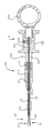
Fig. 1 is the side view according to endoscopic instrument of the present invention.
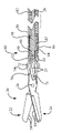
Fig. 2 is the longitudinal section along the endoscopic instrument of Fig. 1 of the line 2-2 intercepting of Fig. 1.
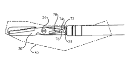
Fig. 3 is that the partial perspective axle of far-end of the endoscopic instrument of Fig. 1 is surveyed view.
Fig. 4 is the partial section of disconnection of far-end of the endoscopic instrument of Fig. 1.
Fig. 5 is that the axle of endoscopic scissors blade that has first specific embodiment of organizing the stopper section of the blade that is connected in endoscopic instrument is surveyed view, and shows the using-system stopper section and keep blood vessel.
Fig. 6 is that the axle of endoscopic scissors blade that has second specific embodiment of organizing the stopper section of the blade that is connected in endoscopic instrument is surveyed view.
Fig. 7 is that the axle of endoscopic scissors blade that has the 3rd specific embodiment of organizing the stopper section of the blade that is connected in endoscopic instrument is surveyed view.
Fig. 8 shows and uses the stopper section of organizing of Fig. 7 to come joining tissue.
Fig. 9 and Figure 10 are the indicative icons of operation of cam pin and the cam path device of endoscopic instrument.
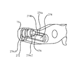
Figure 11 is the indicative icon of end effector that is provided with the substituting specific embodiment of cam pin and cam path device.
Figure 12-the 14th, the partial perspective axonometric chart of the specific embodiment shown in Figure 11.
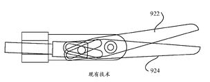
Figure 15 to Figure 17 of prior art is the cam pin of prior art and the indicative icon of the shears end effector that cam path is operated.
Figure 18 to Figure 20 is the indicative icon that is provided with according to the end effector of the guiding push rod of an aspect of endoscopic instrument of the present invention.
Figure 21 is to use the longitudinal stereoscopic figure of a push cam pin assemblies in endoscopic instrument.
Figure 22 is to use the longitudinal stereoscopic figure of the second push cam pin assemblies in endoscopic instrument.
Figure 23 is the exploded view of the push cam pin assemblies shown in Figure 22.
Figure 24 is to use the partial perspective longitudinal stereoscopic figure of the 3rd push cam pin assemblies in endoscopic instrument.
Figure 25 is the exploded view of the part of the push cam pin assemblies shown in Figure 24.
Figure 26 is the axonometric chart of the said part of the push cam pin assemblies shown in Figure 25.
Figure 27 is the sectional view of disconnection of the mid portion of endoscopic instrument.
The specific embodiment
Turn to Fig. 1 to Fig. 4 now, show according to endoscopic instrument 10 of the present invention.Endoscopic instrument 10 comprises: elongated tubular element 12, and it is preferably the flexible construction with near-end 14 and far-end 16; Forked element 18, it is rotatably installed in the far-end 16 of tubular element 12; And end effector assembly 20, its size is set at and can in the service aisle of endoscope, passes through.Control member 28 can move axially and pass tubular element 12 and can be at tubular element 12 internal rotation.The far-end 30 of control member 28 is provided with push rod 32; Push rod 32 is connected in end effector 20; With realize when control member 28 tubular element 12 in during longitudinal translation end effector move with open and close, the scissor action relative motion of carrying out for example is like more detailed argumentation below.Proximal handle assembly 34 is connected in the near-end 14 of tubular element 12 and the near-end 36 of control member 28, to realize the vertical relatively of control member 28 and tubular element 12 and to rotatablely move, like what further discuss below.
With reference to Fig. 3 and Fig. 4, shown in the specific embodiment in, end effector assembly 20 is shears assemblies, it comprises the scissor blade 22,24 of axle on 26 that is installed in forked element 18 pivotally. Blade 22,24 respectively comprises: medial surface 40; Grind (or polishing) face 42, it extends to the sharp cutting edge 44 that intersects with medial surface and ends at cutting edge 44; And the lateral surface 62 opposite with medial surface.Cutting edge 44 extends to the far-end 46 of blade from the position away from pivotal point.
According to an aspect of the present invention, at least one blade preferably, and more preferably be that two blades comprise that friction with cutting edge 44 lateral deviation biases 45 strengthens and organize stopper section 50 (so that not being present in the cutting edge place fully).Bias 45 can be the full blade thickness that departs from cutting edge still preferably less than 0.25 mm (0.012 inch), makes and organizes the stopper section mechanically to attach to lateral surface 62.Organize stopper section 50 to be used for keeping structural pull strength and/or apply pull strength organizationally and do not cut biological tissue; Apply pull strength such as the pull strength on the non-metal article of suture or on non-metal article and do not cut non-metal article keeping such as suture, and not with cutting edge 44 interferences of blade.Advantageously, the far-end 46 of organizing at least a portion of stopper section can be close to scissor blade is provided with, stably to keep tissue and to prevent that it from advancing to the far-end 46 of blade along abradant surface 42.Each organizes stopper section 50 can be set to the insert in the corresponding recess 52, and recess 52 extends in the lateral surface 62 of corresponding blade 22,24.Each organizes stopper section 50 preferably to remain in its recess 52 through welding, bonding, soldering, riveted joint or another kind of mechanical cohesive bond mode or cooperation.Alternatively, organize stopper section 50 can with one or more material material different manufacturings that limit blade 22,24.As just example,, organize stopper section 50 also can constitute by same metal, different metal, carbon composite or polymer composites although blade 22,24 preferably is made up of metal.Organize the stopper section easily to be shaped through molded, casting, machined, photoetching, molding or impression.
As an example, in the specific embodiment shown in Fig. 3 to Fig. 5, organize stopper section 50 to be arranged on two scissor blades 22,24, and comprise a successive gang saw shape tooth projection 54.These projections do not have the enough height or the sharpness of cutting edge 44 tops and wear tissue to cut.These projections are with helping being prone to sliding tissue; Comprise that for example the blood vessel of tremulous pulse 56 keeps in position; Even the position after the leaning on most of the scissor blade of opening 22,24 (for example; At 58 places), and prevent recurrently to skid off to front slide and between the blade along with blade moves to this tissue of closed configuration.Turn to Fig. 6, organize stopper section 50 can be contained in the groove 60 in the abradant surface 42 (wherein the medial surface 40 of blade and lateral surface 62 both surround the some parts of stopper section) substitutingly.Work in the same manner as described above in the stopper section.Substitute as another, it is outside to organize stopper section 50 can be installed in lateral surface 62 top cutters.
Referring now to Fig. 7, show another specific embodiment of organizing stopper section 150 in conjunction with each scissor blade 22,24.Each organizes stopper section 150 to comprise first tenaculum (or grasping needle point), 152 and second tenaculum 154; Wherein first tenaculum, 152 contiguous corresponding blades (for example; Blade 24) far-end setting; But be shifted to near-end with respect to this far-end, second tenaculum 154 is in the near-end of blade and the position between the far-end.In each stopper section 150, far-end tenaculum 152 preferably extends bigger height from abradant surface 42, and than more the tenaculum 154 near end is big.As shown in Figure 8, far-end tenaculum 152 is suitable for puncturing effectively and manipulation of tissue 154 easily, and more is configured to prevent to organize the far-end 46 that slides to blade 24 along abradant surface 42 near the tenaculum of holding 154.
Back with reference to Fig. 3 and Fig. 4, the blade end actuator element 22,24 of end effector assembly 20 moves opening between configuration and the closed configuration through cam pin and cam path assemblies.More specifically, the tang 25 of the proximal end of each blade 22,24 (near axle 26) comprises the cam path 70 (illustrating best about blade 24) of longitudinal extension, and cam path 70 is located with the oblique angle with respect to the longitudinal axis A of tubular element 12.Cam path 70 comprises bilateral widened section 72 (in the both sides of the axis of cam path), and bilateral widened section 72 is preferably placed at the proximal end 74 of cam path.The push rod 32 that is connected in the far-end 30 of control member 28 comprises and is provided with transverse cam pin 76 that cam pin 76 is divided a word with a hyphen at the end of a line in the cam path 70 of each blade 22,24.Discuss the assembling of cam pin 76 to push rod 32 below in detail.When control member 28 through the operation of proximal handle assembly 34 in tubular element 12 during translation; Cause cam pin 76 at cam path 70 internal migrations; Thereby make blade 22,24 move with scissor action; Wherein the relative proximal motion of control member makes blade move in the closed configuration, and is as shown in Figure 9.In closed configuration shown in Figure 9, scissor blade is kept through the tolerance of cam pin and cam path device firmly, around forked element 18, to limit (non-giving) assembly (Fig. 3) of rigidity " non-giving ".This possibly have difficulties when the firm and crooked relatively entry port 80 (being shown in broken lines) of the service aisle through endoscope is handled the end effector assembly, especially under the situation when using the long end effector of long scissor blade or other.Yet; Shown in figure 10; When cam pin further retracts in the bilateral widened section 72 of near-end 74 of cam path 70,, rotates jointly along same direction around the longitudinal axis A of apparatus cam pin 76 with the blade 22,24 that allows end effector assembly 20 for providing enough spaces.This has shortened the inflexible length of rigidity of end effector assembly 20 effectively, thus the entering part 80 that allows long end effector assembly 20 to pass through and get into the service aisle of endoscope.Like this, shown in figure 10, can use long rigid tip executor 20 by cam pin and the operation of cam path device.
In Fig. 9 and Figure 10, the near-end of tang 25 need have the near-end widened section, to give the bilateral widened section 72 that is formed on groove wherein the space is provided.This causes the near-end of end effector 20 to have the width of relative broad, and when end effector was in complete closed configuration, this width can extend to outside the forked element.This part of end effector can with cross protection big envelope that forked element extends or with the entry port interference of endoscope.
Referring now to Figure 11 to Figure 14, show another specific embodiment of cam pin and cam path device.Cam path 274 is stair-stepping, so that limit the inner side slot part 274a of broad and narrower outer side slot part 274b (cam path 74 than among Fig. 3,4 and 9 is little).Inboard and the outside are that the longitudinal axis with respect to apparatus limits, and wherein the inboard is more near this longitudinal axis, and the outside is far away from longitudinal axis, and are opening between configuration and the closed configuration in the mobile plane of being passed at end effector.Outer side slot part 276a comprises the proximal slot 272a that widens, and wherein width is to be parallel to end effector to move the plane survey of being passed opening between configuration and the closed configuration.Inner side slot part 274b is uncovered and near the proximal slot 272a that widens at the proximal slot 272a place of widening.Cam pin 276 also has the diameter of scalariform, has: mid portion 276a, and cam pin 276 is connected in push rod 232 at mid portion 276a place; Contiguous and be positioned at the first diameter inside part 274a1, the 274a2 on the either side of mid portion 276a; And it is contiguous and be positioned at the less second diameter Outboard Sections 276c1, the 276c2 on the either side of inside part 274a1,274a2.In the most of stroke of cam pin 276 in cam path 274; The size of each inside part 274a1,274a2 is set in the inner side slot part 272a of corresponding end effector element and closely divides a word with a hyphen at the end of a line, and the size of each Outboard Sections 276c1,276c2 is set at outside and closely divides a word with a hyphen at the end of a line in the side channel part 274b.With reference to Figure 13, when end effector was in complete closed configuration, the inside part of cam pin 276 and Outboard Sections be all right to enter the groove of the widening zone 272a at cam path 274 places of the rear end of end effector element.Being limited in the boundary of widened section 272 of cam path 274 of cam pin 276 than minor diameter Outboard Sections 276c1,276c2, and get in " air " and leave inner side slot part 274a than major diameter inside part 276b1,276b2.With reference to Figure 14, inside part 276b1,276b2 can further cross tang and advance backward, straddle in the rear end of tang 75.This provides the gradient that allows end effector element 22,24 to be rotated in together when (being used for being inserted into the entering part of endoscope) when in closed configuration; Reduced the near-end size of whole end effector 20 when in closed configuration; And allow end effector element 22,24 to be closed together, to reduce closed configuration lower end executor 20 distal dimension through (in the specific embodiment shown in Fig. 9 and 10) relatively large swing.
Figure 15 to Figure 17 with reference to prior art; Recognize; Push rod 932 to be to move to end effector 922,924 when opening configuration (Figure 17) from closed configuration (Figure 15) before with respect to forked element 918, in the hole of forked element 918, provides enough space to allow push rod 932 with respect to axially bored line A
BRemove from concentric position, and cause push rod 932 to tilt.Even very under the situation of slight inclination, cam pin 976 also moves to the off-center position in its stroke at push rod 932.This misalignment causes end effector 922,924 to move to when opening in the configuration (Figure 17) with respect to axially bored line A at them
BRotate with asymmetric theta alignment mode.The difficulty that apparatus control accuracy that this causes reducing and operator engage destination organization and on destination organization, operate.
Turn to Figure 18 to Figure 20 now, in order to eliminate end effector 320,322 around axially bored line A
BAsymmetric opening, the far-end of push rod 332 is formed with or otherwise is connected in alignment guide 333.Alignment guide 333 comprises having the cannelure 335 that extends out opening 337.When guiding piece advances so that end effector is moved to closed configuration with respect to end effector, the opening 337 that extends out of guiding piece is ridden and is leaned against on the axle 26 (Figure 19).When push rod was advanced further, axle 26 is constrained in groove 335 advanced, even and guaranteed at push rod with respect to axially bored line A
BEnd effector 320,322 also can be opened (Figure 20) symmetrically during inclination.Although accompanying drawing combines traditional shears end effector to show this conception, any one that this aspect of the present invention also can be in the end effector that this paper quotes from used.
The cam pin that is used for the Fig. 3 and the specific embodiment shown in Figure 4 can be connected in push rod with any traditional mode.With reference to Figure 21, a kind of traditional mode be provided for machined push rod 32 and cam pin 76 both and with interference fit both are combined together.This needs the external diameter of cam pin 76 and passes very accurate dimensional tolerance between the internal diameter of transverse holes 39 of push rod.A kind of mode of making these parts needs the CNC machined, and this causes higher relatively constructions cost.In addition, use this design and manufacturing, if these parts not in required tolerance, cam pin 76 may be removed from push rod 32 immodestly so.
According to another aspect of the present invention, provide a kind of alternate configurations to be used for cam pin is matched with the push rod of the open and close of handling end effector.In first specific embodiment of the alternate configurations shown in Figure 22 and 23, cam pin 476 is machined to the smooth cylinder with annular protrusion 477, annular protrusion 477 at least in part, preferably fully around cylindrical circumferential extension.Push rod 432 is formed by four component-assembled: tabular central neck portion part 434; Two flat outer neck part 435a, 435b locate one on each side of central neck portion part both sides; And the proximal tubular base portion 437 that holds above-mentioned three neck member at its far-end.Three neck member 434,435a, 435b are preferably by photoetching (PCM) or be embossed into the configuration of present description.Central neck portion part 434 is elongated boards, and it has the circular open that extends through this plate 441 that is positioned at its far-end.The size of circular open 441 is set the annular protrusion 477 that closely holds cam pin for.Thickness in the dimension of plate in extending the plane of plate promptly can be increased around the some parts of circular open 441 at 443 places, to keep structural intergrity. Outer neck part 435a, 435b are the elongated board that has with the basic equal length of central neck portion part, and in passing the planar dimension of plate, are provided with the near-end width and reduce part 445a, 445b. Outer neck part 435a, 435b have circular open 447a, 447b separately, and the size of circular open 447a, 447b is set the smooth column part that closely holds cam pin 476 for, but diameter is too little annular protrusion 477 is passed through.When assembling, cam pin 476 is positioned in the central neck portion part 434, and wherein annular protrusion 477 is positioned at opening 441.Then, outer neck part 435a, 435b are located one in each of cam pin 476 above the end, so that annular protrusion 477 is remained in the opening of central neck portion part 434.Three neck member 434,435a, 435b then with sandwich by spot welding or otherwise be coupled together, producing the assembling that maintains cam pin 476 effectively, and thus, cam pin can not fluff.The assembly of welding is inserted in the opening 449 of far-end of tubulose base portion 437 then, and is laser-welded to the tubulose base portion, to accomplish the assembling of cam pin to push rod.This assembling can be by automatization, and bigger manufacturing ability when allowing close tolerance required when parts are machined to the tradition assembling through CNC.
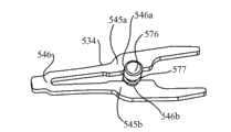
With reference to Figure 24 to Figure 26, show second specific embodiment of push cam pin assemblies, its can be used for Fig. 3 and 4 and Figure 11 to the specific embodiment of end effector shown in Figure 14.Cam pin 576 limits mating groove 577.Single machined or platen 534 form two arm 545a, the 545b that is connected in bridging part 546 places.The inboard of arm is limited to mating groove 577 interior extensions and therefore catches isometrical recess 546a, the 546b of cam pin 576.The far-end of arm preferably still forms guide portion 535 alternatively, and guide portion 535 works as described in Figure 18 to Figure 20 as top.With reference to Figure 25, arm 545a, 545b can form (being used to be arranged in around the cam pin 576) to open configuration.Then, arm is closed and by laser weld or otherwise be fastened to together in the cam pin bent around, becomes sub-component shown in Figure 26 580.Alternately, arm 545a, 545b can form closed basically, and do not have enough spaces to hold cam pin.Arm 545a, 545b then flexibly bending open holding cam pin 576, and be released then to rebound rapidly around cam pin 576.Arm 545a, 545b then preferably around the cam pin by laser weld or otherwise be fastened to together.In case plate 535 has been fastened on around the cam pin 576, the near-end of the plate of contiguous bridge part 546 just is fixed in tubulose base portion 537 then, to accomplish assembling.
With reference to another aspect of apparatus, end effector assembly 20 can rotate around the axis of tubular element 12 through the rotation of control member 28 when being activated by proximal handle 30.Get back to Fig. 4 once more, the effective and level and smooth rotation when receiving the moment of torsion at proximal handle assembly 30 places at control member 28 utilizes swivel bearing assembly 80 that forked element is installed on tubular element.More specifically, inner bearing 82 is fixed in the far-end 16 of tubular element through bonding, welding or such as any of the mechanical system of crimping.Inner bearing 82 comprises the far-end bearing surface from the remote extension of tubular element.Bearing surface comprises distal face 84 and circumferential surface 86.The proximal end face 88 of forked element 18 rotatably rests on the distal face 84 of inner bearing 82.Outer bearing 90 is rotatably installed on the said circumferential surface 84 of said inner bearing 82; And for example be fastened on around the proximal part 92 of forked element 18, thereby forked element longitudinally be anchored on inner bearing 82 and therefore be anchored on tubular element with mode that can smooth-going rotation through crimping.Therefore the moment of torsion that puts on control member 28 is passed to the cam pin 76 of push rod 32 and its far-end, thereby directly makes end effector 22,24 far-end rotation around tubular element 16 on forked element 18.Importantly, moment of torsion is directly put on end effector 22,24 but not forked element 18 (control member 28 is removed with forked element 18 and connected).
Referring now to Figure 27, tubular element 12 is preferably flat or circular wire-wound coil 94, and its qualification has the flexible structure of slick polymer flexibility outer sleeve 96.Control member 28 is configured to have different moments of torsion and longitudinal rigidity along the proximal part of its length with distal portions.Control member 28 preferably is made up of the isolating proximal part and the distal portions that are connected with connection element 98, and connection element 98 for example is the hypotube of one section weak point, and it is crimped to connect these parts.The preferably single spring steel of proximal part 100 rustless metal silk or flexible compound carbon-point, but also can process (twining) by the biradial cable that winds the line as the opposite direction in " velometer " cable edge.Distal portions 102 has 8 to 20 inches length; It more preferably is about 12 inches long; And be the cable or drawing pyrite thigh (DBS) cable of the thin multiply of the above-mentioned type; Promptly from mould, extracted and by the cable of soldering, so that under opposing edge and the situation of twining the load rotation on the opposite direction, reduce the unfolded trend of cable so that line is bonded together.Alternately, distal portions is single superelastic metal silk.Distal portions can provide resilient flexibility significantly and moment of torsion (clockwise with counterclockwise) accurately and orientation apply uniformly and do not cause and jump or prominent moving (inhomogeneous or rotation suddenly).Use two separated portions cost, function and repeatable aspect optimized control member.In the close end office of apparatus, it is straight relatively that apparatus keeps during use, and individual wire or compound bar 100 are suitable for transmitting length travel and the rotation torque from proximal handle easily.When the crooked zigzag path through highly crooked (perhaps or even opisthotonos) endoscope of apparatus, the distal portions of apparatus possibly suffer violent distortion.The cable of multiply or ultra snap the line are suitable for realizing along the vertical shift of these parts of apparatus well and even provide when the serious crooked or opisthotonos of the far-end of apparatus accurately and directed moment of torsion uniformly.As stated, the far-end of control member 28 is provided with push rod 32, but also can provide other distal structure to be used for control member is attached to end effector.Be provided with polymeric tubular bearing 104 at control member 28 and coiling between the coil 94, to occupy the space between these two elements and to prevent the bending of control member 28.
Back with reference to Fig. 1 and 2, Handleset 34 comprises axle 100, and axle 100 has far-end 111, near-end thumb rings 112 and cannelure 114.Lasso 118 is rotatably mounted in the far-end 111 of the axle 110 that is communicated with cannelure 114.The near-end of tubular element 14 is fixed in the lasso 118.Finger central siphon 120 can be in vertical shift on the axle 110 at groove 114.The near-end 122 of control member is for example fixing with central siphon 120 through dog screw 124.The vertical shift of central siphon 120 on axle causes the operation of control member 28 with respect to the vertical shift and the end effector of tubular element 12, as stated.Axle 110 and central siphon 120 cause control member 28 with respect to the rotation of tubular element 12 and end effector element 22,24 rotations with respect to tubular element that therefore produce, equally as stated with respect to the rotation of lasso 118.
Here described and illustrated the specific embodiment of endoscopic instrument.Although described the specific specific embodiment of the present invention, and be not intended to and make the present invention be limited to these specific embodiment, because be intended to make the present invention wide as much as possible in the scope that this area allowed, and description is understood in the same way.Therefore, although described this apparatus, will be appreciated that numerous aspects of this device can be applied in other endoscopic instruments of the end effector that has except that scissor blade especially in regard to scissors apparatus.For example, cam path design, the rotatable bearing support of end effector and the control member that is used for the operational tip executor all are the conceptions that generally can be applicable to comprise the endoscopic instrument of clasper and pliers at least.In addition; Although about scissor blade disclose two exemplary depart from organize the stopper section, its hetero-organization stopper section design according to the present invention can be arranged at the abradant surface extension of cutting edge and the adjacently situated surfaces opposite with medial surface of scissor blade.Therefore, those of ordinary skills can recognize, can under the situation of the spirit and scope of the invention that does not depart from the requirement protection, carry out other other changes to the invention that is provided.
Claims (43)
1. endoscopic scissors apparatus comprises:
A) tubular element, it has near-end and far-end, and limits longitudinal axis;
B) control member, it has near-end and far-end, and extends through said tubular element;
C) be arranged on the end effector assembly of the far-end of said tubular element; Said end effector assembly comprises first executive component and second executive component; In the said executive component at least one can move with respect to another; The said far-end of said control member operationally connects with respect to said executive component, thereby said control member makes said executive component between the open and close configuration, move with respect to the longitudinal translation of said tubular element; And
D) proximal handle assembly is used to make said control member and said tubular element relative to each other to move, and opens relatively moving between configuration and the said closed configuration to realize said executive component said.
2. endoscopic scissors apparatus comprises:
A) tubular element, it has near-end and far-end, and limits longitudinal axis;
B) control member, it has near-end and far-end, and extends through said tubular element;
C) be arranged on the end effector assembly of the far-end of said tubular element; Said end effector assembly comprises first scissor blade and second scissor blade; In the said scissor blade at least one can move with respect to another; The said far-end of said control member operationally connects with respect to said scissor blade, thereby said control member makes said scissor blade move opening between configuration and the closed configuration with respect to the longitudinal translation of said tubular element
Said first scissor blade has medial surface, abradant surface and is positioned at sharp cutting edge and the lateral surface opposite with said medial surface of the intersection of said medial surface and said abradant surface; And
Said second scissor blade has medial surface, abradant surface and is positioned at sharp cutting edge and the lateral surface opposite with said medial surface of the intersection of said medial surface and said abradant surface;
D) stopper section is organized in the friction enhancing; It mechanically is connected at least one said abradant surface or at least one in the lateral surface in said first scissor blade and said second scissor blade, and the said said cutting edge of stopper section and corresponding blade of organizing laterally departs from; And
E) proximal handle assembly, it is used to make said control member and said tubular element relative to each other to move, and opens relatively moving between configuration and the said closed configuration to realize said scissor blade said.
3. endoscopic scissors apparatus according to claim 2, wherein:
Saidly organize the stopper section to be configured to keep but do not cut biological tissue or suture.
4. endoscopic scissors apparatus according to claim 2, wherein:
At least one said scissor blade can be with respect to said another scissor blade rotation.
5. endoscopic scissors apparatus according to claim 4, wherein:
In said first scissor blade and said second scissor blade each all rotatably is connected in said forked element, and the said far-end of said control member is connected in said first scissor blade and said second scissor blade.
6. endoscopic scissors apparatus according to claim 2, wherein:
With organizing the stopper section to be set to each said abradant surface or the lateral surface in said first scissor blade and said second scissor blade.
7. endoscopic scissors apparatus according to claim 2, wherein:
In said abradant surface or the lateral surface said at least one be included in the upwardly extending opening of near-end-far end party, and the said stopper section of organizing is to be individually formed and to be installed in the isolating element in the said opening with corresponding scissor blade.
8. endoscopic scissors apparatus according to claim 6, wherein:
Said opening is a groove.
9. endoscopic scissors apparatus according to claim 6, wherein:
Said opening is an open recess on the said outside.
10. endoscopic scissors apparatus according to claim 2, wherein:
The said stopper section of organizing mechanically is adhered to said scissor blade.
11. endoscopic scissors apparatus according to claim 2, wherein:
The said stopper section of organizing comprises at least one grasping needle point.
12. endoscopic scissors apparatus according to claim 2, wherein:
The said stopper section of organizing comprises the first grasping needle point and the second grasping needle point.
13. endoscopic scissors apparatus according to claim 12, wherein:
Said at least one far-end in said needle point tenaculum and said abradant surface or the lateral surface is adjacent to be provided with, and the contiguous said first needle point setting of said second needle point.
14. endoscopic scissors apparatus according to claim 2, wherein:
The said stopper section of organizing comprises a toothrow shape projection of extending along the length of said abradant surface or lateral surface.
15. endoscopic scissors apparatus according to claim 14, wherein:
Said dentation is successive.
16. endoscopic scissors apparatus according to claim 2, wherein:
Said tubular element is a resilient flexibility fully, so that pass the tortuous passageway of the endoscope of opisthotonos.
17. an endoscopic scissors apparatus comprises:
A) tubular element, it has near-end and far-end, and limits longitudinal axis;
B) control member, it has near-end and far-end, and extends through said tubular element;
C) forked element, it rotatably is connected in the far-end of said tubular element;
D) end effector assembly; It comprises first scissor blade and second scissor blade; In the said scissor blade at least one is installed on said forked element and can moves with respect to another scissor blade, and the said far-end of said control member is connected in said at least one scissor blade movably;
Said first scissor blade has medial surface, abradant surface and is positioned at sharp cutting edge and the lateral surface opposite with said medial surface of the intersection of said medial surface and said abradant surface; And
Said second scissor blade has medial surface, abradant surface and is positioned at sharp cutting edge and the lateral surface opposite with said medial surface of the intersection of said medial surface and said abradant surface; And
In the said abradant surface of said first scissor blade and said second scissor blade or the lateral surface said at least one comprise that friction strengthens and organize the stopper section; Said friction strengthen organize the stopper section to be installed in said abradant surface or the lateral surface or on, and laterally depart from the said cutting edge of corresponding blade; And
E) proximal handle assembly; It is connected in the said near-end of said tubular element and said control member; Be used to make said control member and said tubular element relative to each other longitudinally and rotatably to move, opening relatively moving between configuration and the closed configuration to realize said scissor blade.
18. endoscopic scissors apparatus according to claim 17, wherein:
Said control member has along its length from its near-end and reverses and bending stiffness towards what its far-end reduced.
19. endoscopic scissors apparatus according to claim 17, wherein:
Said at least one rotatable scissor blade comprises cam path, and the said far-end of said control member is connected in the cam pin at said cam path internal migration, to realize relative to each other moving between open position and make position of said scissor blade.
20. endoscopic scissors apparatus according to claim 19, wherein:
Said first scissor blade and the said second scissor blade both are rotatably mounted in said forked element; And the said cam path in each in the said scissor blade comprises the bilateral widened section of near-end; Thereby when said cam pin retraction so that said scissor blade is moved to said closed configuration, said cam pin further retracts to and allows said scissor blade together to a sideway swivel of said longitudinal axis in the said bilateral widened section.
21. endoscopic scissors apparatus according to claim 17, wherein:
Saidly organize the stopper section to be configured to keep but do not cut the tissue of inside of human body.
22. endoscopic scissors apparatus according to claim 17, wherein:
The said abradant surface of each in said first scissor blade and said second scissor blade all holds organizes the stopper section.
23. endoscopic scissors apparatus according to claim 16, wherein:
Said tubular element is a resilient flexibility fully, so that pass the tortuous passageway of the endoscope of opisthotonos.
24. an endoscopic instrument comprises:
A) tubular element, it has near-end and far-end, and limits longitudinal axis;
B) control member, it has near-end and far-end, and extends through said tubular element;
C) proximal handle assembly, it is used to make said control member and said tubular element relative to each other to move;
D) be connected in the cam pin of the said far-end of said control member;
E) be connected in the forked element of the said far-end of said tubular element; And
F) be rotatably installed in first end effector and second end effector on the said forked element;
In the said end effector each all comprises the cam path of longitudinal extension; One end of said cam path has bilateral widened section; The vertical shift of wherein said cam pin in said cam path realizes that said end effector opening moving between configuration and the closed configuration; Wherein the said end effector of the mobile realization on first direction gets into moving of closed configuration, and said cam pin allows said end effector together to a sideway swivel of said longitudinal axis along in said cam path, being moved further and getting into said bilateral widened section on the said first direction.
25. endoscopic instrument according to claim 24, wherein:
Said bilateral widened section is arranged on the near-end of said cam path, and said first direction is the retraction direction along relative proximal direction.
26. endoscopic instrument according to claim 24, wherein:
Said cam path is crossed over corresponding to the near-end-distal length of the diameter at least of said cam pin and is widened by bilateral.
27. endoscopic instrument according to claim 24, wherein:
The said bilateral widened section of said cam path has the lateral separation less than the width of said end effector in this zone.
28. endoscopic instrument according to claim 24, wherein:
Said end effector is a scissor blade.
29. endoscopic instrument according to claim 24, wherein:
Said forked element is rotatably mounted in the said far-end of said tubular element.
30. endoscopic instrument according to claim 24, wherein:
Said tubular element is a resilient flexibility fully, so that pass the tortuous passageway of the endoscope of opisthotonos.
31. endoscopic instrument according to claim 24, wherein:
Said control member has length and along said length reversing and bending stiffness near-end reducing to the distal direction.
32. endoscopic instrument according to claim 24, wherein:
The said cam path of each in said first end effector and said second end effector is scalariform dimensionally, to limit the outer side slot part of inner side slot part and relative narrower; And
Said cam pin is scalariform dimensionally, with first diameter parts that is limited to said inner side slot part internal migration with at the second less relatively diameter parts of said outer side slot part internal migration.
33. endoscopic instrument according to claim 32, wherein:
The said inner side slot of each in said first end effector and said second end effector partly has open near-end.
34. an endoscopic instrument comprises:
A) tubular element, it has near-end and far-end, and limits longitudinal axis;
B) control member, it has near-end and far-end, and extends through said tubular element;
C) proximal handle assembly, it is used to make said control member and said tubular element relative to each other to move;
D) be connected in the forked element of the said far-end of said tubular element, said forked element limits longitudinal axis;
E) be rotatably installed in a place and state first end effector and second end effector on the forked element; And
F) push rod; It is fixed in the said far-end of said control member and extends through said forked element; Said push rod is connected in said end effector, thereby said push rod makes said end effector move opening between configuration and the closed configuration with respect to the vertical shift of said forked element, and said push rod is provided with the far-end alignment guide; When said end effector moves to said when opening configuration; Said far-end alignment guide is extended around said axle, and guiding said push rod with respect to the moving of said axle, thereby said end effector is opened around said longitudinal axis symmetrically.
35. endoscopic instrument according to claim 34, wherein:
Said alignment guide comprises the cannelure with the distal openings of extending out, and wherein when said push rod moved forward with respect to said forked element far-end, said alignment guide was with self being aligned on the said axle.
36. endoscopic instrument according to claim 34, wherein:
Said push rod comprises near the cam pin that is positioned at the said alignment guide; And said end effector limits cam path; Said cam pin is divided a word with a hyphen at the end of a line in said cam path, opens moving between configuration and the said closed configuration to realize said end effector said.
37. an endoscopic instrument comprises:
A) tubular element, it has near-end and far-end, and limits longitudinal axis;
B) be connected in the forked element of the said far-end of said tubular element;
C) be installed in first end effector and second end effector on the said forked element, at least one in the said end effector can move and comprise cam path with respect to another;
D) control member, it has near-end and far-end, and extends through said tubular element;
E) be fixed on the push rod of the said far-end of said control member, said push rod is included in the cam pin of said cam path internal migration; And
F) be connected in the proximal handle assembly of said control member and said tubular element, it is used to make said cam pin in said cam path, to move, so that said end effector moves opening between configuration and the closed configuration;
Wherein, said cam pin has core, and said core is scalariform on diameter with respect to peripheral part of said cam pin, and said push rod is captured in said cam pin the said central part office of said cam pin.
38. according to the described endoscopic instrument of claim 37, wherein:
The said core of said cam pin has the diameter bigger than said peripheral part; And
Said push rod comprises three plates; Said three plates comprise central plate and two external plates; Said central plate limits first diametric hole of the said core that holds said cam pin; Said two external plates have second diametric hole littler than said first diametric hole separately, and the said core of wherein said cam pin is contained in said first diametric hole of said central plate, and said peripheral part of said cam pin is contained in said second diametric hole of said two external plates.
39. according to the described endoscopic instrument of claim 38, wherein:
Said three plates are fixed by welding in together.
40. according to the described endoscopic instrument of claim 38, wherein:
The said core of said cam pin have the groove that limits in the said cam pin than minor diameter; And
Said push rod comprises two arms, and said two arms have the recess that occupy in the said groove.
41. according to the described endoscopic instrument of claim 40, wherein:
Said push rod comprises plate, and said plate limits said two arms and with said two bridge parts that arm links together.
42. according to the described endoscopic instrument of claim 37, wherein:
Said end effector is installed on said forked element and is installed on the axle; And said push rod is provided with the far-end alignment guide; When said end effector moves to saidly when opening configuration, said far-end alignment guide is extended around said axle, to guide said push rod moving with respect to said axle.
43. according to the described endoscopic instrument of claim 42, wherein:
Said push rod comprises plate, and said plate limits said two arms and with said two bridge parts that arm links together, said guiding piece is limited said arm.
Priority Applications (1)
| Application Number | Priority Date | Filing Date | Title |
|---|---|---|---|
| CN201510003440.7A CN104840238B (en) | 2009-05-22 | 2010-05-21 | Endoscopic instrument |
Applications Claiming Priority (9)
| Application Number | Priority Date | Filing Date | Title |
|---|---|---|---|
| US12/471041 | 2009-05-22 | ||
| US12/471,066 US20100298854A1 (en) | 2009-05-22 | 2009-05-22 | Endoscopic Instrument with Control Member Having Decreasing Torsional and Flexural Stiffness Along Its Length |
| US12/471,024 US9277932B2 (en) | 2009-05-22 | 2009-05-22 | Endoscopic scissors instrument with friction enhancing tissue stops |
| US12/471057 | 2009-05-22 | ||
| US12/471066 | 2009-05-22 | ||
| US12/471,057 US20100298853A1 (en) | 2009-05-22 | 2009-05-22 | Endoscopic Instrument Having Rotatably Mounted End Effector Assembly |
| US12/471024 | 2009-05-22 | ||
| US12/471,041 US8690909B2 (en) | 2009-05-22 | 2009-05-22 | Endoscopic instrument with bi-laterally widened cam-slot at end effector |
| PCT/US2010/035714 WO2010135615A1 (en) | 2009-05-22 | 2010-05-21 | Endoscopic instrument |
Related Child Applications (1)
| Application Number | Title | Priority Date | Filing Date |
|---|---|---|---|
| CN201510003440.7A Division CN104840238B (en) | 2009-05-22 | 2010-05-21 | Endoscopic instrument |
Publications (1)
| Publication Number | Publication Date |
|---|---|
| CN102573672A true CN102573672A (en) | 2012-07-11 |
Family
ID=43126519
Family Applications (2)
| Application Number | Title | Priority Date | Filing Date |
|---|---|---|---|
| CN2010800326218A Pending CN102573672A (en) | 2009-05-22 | 2010-05-21 | Endoscopic instrument |
| CN201510003440.7A Active CN104840238B (en) | 2009-05-22 | 2010-05-21 | Endoscopic instrument |
Family Applications After (1)
| Application Number | Title | Priority Date | Filing Date |
|---|---|---|---|
| CN201510003440.7A Active CN104840238B (en) | 2009-05-22 | 2010-05-21 | Endoscopic instrument |
Country Status (8)
| Country | Link |
|---|---|
| EP (1) | EP2432406B1 (en) |
| JP (1) | JP5671682B2 (en) |
| CN (2) | CN102573672A (en) |
| AU (1) | AU2010249437B2 (en) |
| BR (1) | BRPI1012156A2 (en) |
| CA (1) | CA2762172A1 (en) |
| ES (1) | ES2752055T3 (en) |
| WO (1) | WO2010135615A1 (en) |
Cited By (5)
| Publication number | Priority date | Publication date | Assignee | Title |
|---|---|---|---|---|
| CN106572874A (en) * | 2014-07-28 | 2017-04-19 | 泰利福医疗公司 | Needlescopic scissor end effector and method of use |
| CN109106425A (en) * | 2018-09-17 | 2019-01-01 | 南京市第医院 | One kind is intravascular to take object to clamp |
| CN109875653A (en) * | 2019-03-11 | 2019-06-14 | 南京市第一医院 | The minimally invasive incision of osteofascial compartment syndrome subtracts prop tool |
| WO2020248719A1 (en) * | 2019-06-13 | 2020-12-17 | 中国人民解放军陆军军医大学第一附属医院 | Flexible medical scissors |
| CN113038897A (en) * | 2018-11-20 | 2021-06-25 | 科瑞欧医疗有限公司 | Interface joint for interconnecting an electrosurgical generator and an electrosurgical instrument |
Families Citing this family (5)
| Publication number | Priority date | Publication date | Assignee | Title |
|---|---|---|---|---|
| US9364239B2 (en) * | 2011-12-19 | 2016-06-14 | Covidien Lp | Jaw closure mechanism for a surgical clip applier |
| JP6737652B2 (en) * | 2016-07-12 | 2020-08-12 | オリンパス株式会社 | Medical device wire and medical device |
| US10779813B2 (en) * | 2018-01-10 | 2020-09-22 | C.R. Bard, Inc. | Articulating surgical instruments |
| US11020214B2 (en) * | 2018-03-29 | 2021-06-01 | Boston Scientific Scimed, Inc. | Devices, systems, and methods for pyloric occlusion |
| DE102021201311A1 (en) | 2021-02-11 | 2022-08-11 | Aesculap Ag | Surgical instrument, tooling for such a surgical instrument and method for manufacturing such a tooling |
Citations (9)
| Publication number | Priority date | Publication date | Assignee | Title |
|---|---|---|---|---|
| US2012648A (en) * | 1933-06-10 | 1935-08-27 | Wheeler Howard Murwin | Florist's shears |
| US5439471A (en) * | 1994-01-05 | 1995-08-08 | Kerr; Harry D. | Combined surgical needle holder and scissors |
| US5496347A (en) * | 1993-03-30 | 1996-03-05 | Olympus Optical Co., Ltd. | Surgical instrument |
| CN1163558A (en) * | 1994-10-11 | 1997-10-29 | 查尔斯·H·克利曼 | Endoscopic instrument with detachable end effector |
| US5904702A (en) * | 1997-08-14 | 1999-05-18 | University Of Massachusetts | Instrument for thoracic surgical procedures |
| US6015412A (en) * | 1997-01-08 | 2000-01-18 | Atlantech Medical Devices Limited | Cutting device |
| CN2868212Y (en) * | 2005-11-11 | 2007-02-14 | 钟李宽 | Random-replaceable laparoscope surgical forceps |
| US20070244515A1 (en) * | 2004-10-14 | 2007-10-18 | Fanous Medhat Y Z | Multipurpose Surgical Tool |
| US7494501B2 (en) * | 2003-11-12 | 2009-02-24 | Applied Medical Resources Corporation | Overmolded grasper jaw |
Family Cites Families (6)
| Publication number | Priority date | Publication date | Assignee | Title |
|---|---|---|---|---|
| US2052870A (en) * | 1936-02-18 | 1936-09-01 | Sara Coco | Clamping device |
| DE19521257C2 (en) * | 1995-06-10 | 1999-01-28 | Winter & Ibe Olympus | Surgical forceps |
| US5758422A (en) * | 1996-11-13 | 1998-06-02 | Frank; Lisa Deborah | Scissors with interchangeable blades |
| US9089355B2 (en) * | 2003-09-16 | 2015-07-28 | Vitalitec International, Inc. | Surgical clamp inserts with hooked traction elements |
| EP2022417B1 (en) * | 2004-02-27 | 2010-04-07 | Applied Medical Resources Corporation | System for actuating a laparoscopic surgical instrument |
| CN201019780Y (en) * | 2007-04-24 | 2008-02-13 | 南京微创医学科技有限公司 | Biopsy sampling forceps |
-
2010
- 2010-05-21 BR BRPI1012156A patent/BRPI1012156A2/en not_active IP Right Cessation
- 2010-05-21 AU AU2010249437A patent/AU2010249437B2/en not_active Ceased
- 2010-05-21 EP EP10778444.9A patent/EP2432406B1/en active Active
- 2010-05-21 JP JP2012512054A patent/JP5671682B2/en active Active
- 2010-05-21 CN CN2010800326218A patent/CN102573672A/en active Pending
- 2010-05-21 CN CN201510003440.7A patent/CN104840238B/en active Active
- 2010-05-21 CA CA2762172A patent/CA2762172A1/en not_active Abandoned
- 2010-05-21 WO PCT/US2010/035714 patent/WO2010135615A1/en active Application Filing
- 2010-05-21 ES ES10778444T patent/ES2752055T3/en active Active
Patent Citations (9)
| Publication number | Priority date | Publication date | Assignee | Title |
|---|---|---|---|---|
| US2012648A (en) * | 1933-06-10 | 1935-08-27 | Wheeler Howard Murwin | Florist's shears |
| US5496347A (en) * | 1993-03-30 | 1996-03-05 | Olympus Optical Co., Ltd. | Surgical instrument |
| US5439471A (en) * | 1994-01-05 | 1995-08-08 | Kerr; Harry D. | Combined surgical needle holder and scissors |
| CN1163558A (en) * | 1994-10-11 | 1997-10-29 | 查尔斯·H·克利曼 | Endoscopic instrument with detachable end effector |
| US6015412A (en) * | 1997-01-08 | 2000-01-18 | Atlantech Medical Devices Limited | Cutting device |
| US5904702A (en) * | 1997-08-14 | 1999-05-18 | University Of Massachusetts | Instrument for thoracic surgical procedures |
| US7494501B2 (en) * | 2003-11-12 | 2009-02-24 | Applied Medical Resources Corporation | Overmolded grasper jaw |
| US20070244515A1 (en) * | 2004-10-14 | 2007-10-18 | Fanous Medhat Y Z | Multipurpose Surgical Tool |
| CN2868212Y (en) * | 2005-11-11 | 2007-02-14 | 钟李宽 | Random-replaceable laparoscope surgical forceps |
Cited By (8)
| Publication number | Priority date | Publication date | Assignee | Title |
|---|---|---|---|---|
| CN106572874A (en) * | 2014-07-28 | 2017-04-19 | 泰利福医疗公司 | Needlescopic scissor end effector and method of use |
| CN106572874B (en) * | 2014-07-28 | 2019-05-07 | 泰利福医疗公司 | The scissors end effector and application method of pin type |
| US10765443B2 (en) | 2014-07-28 | 2020-09-08 | Teleflex Medical Incorporated | Needlescopic scissor end effector and methods of use |
| CN109106425A (en) * | 2018-09-17 | 2019-01-01 | 南京市第医院 | One kind is intravascular to take object to clamp |
| CN113038897A (en) * | 2018-11-20 | 2021-06-25 | 科瑞欧医疗有限公司 | Interface joint for interconnecting an electrosurgical generator and an electrosurgical instrument |
| CN109875653A (en) * | 2019-03-11 | 2019-06-14 | 南京市第一医院 | The minimally invasive incision of osteofascial compartment syndrome subtracts prop tool |
| WO2020248719A1 (en) * | 2019-06-13 | 2020-12-17 | 中国人民解放军陆军军医大学第一附属医院 | Flexible medical scissors |
| US11350962B2 (en) | 2019-06-13 | 2022-06-07 | The First Hospital Affiliated To Army Medical Univ | Flexible medical scissors |
Also Published As
| Publication number | Publication date |
|---|---|
| ES2752055T3 (en) | 2020-04-02 |
| EP2432406B1 (en) | 2019-07-24 |
| EP2432406A1 (en) | 2012-03-28 |
| CA2762172A1 (en) | 2010-11-25 |
| CN104840238A (en) | 2015-08-19 |
| BRPI1012156A2 (en) | 2016-04-05 |
| WO2010135615A1 (en) | 2010-11-25 |
| EP2432406A4 (en) | 2013-08-28 |
| CN104840238B (en) | 2017-09-08 |
| AU2010249437B2 (en) | 2015-01-22 |
| JP2012527328A (en) | 2012-11-08 |
| JP5671682B2 (en) | 2015-02-18 |
| AU2010249437A1 (en) | 2011-12-08 |
Similar Documents
| Publication | Publication Date | Title |
|---|---|---|
| CN102573672A (en) | Endoscopic instrument | |
| US9566082B2 (en) | Endoscopic instrument | |
| US10568613B2 (en) | Multi-linked endoscopic device with spherical distal assembly | |
| US7951165B2 (en) | Endoscopic medical instrument and related methods of use | |
| CN110799136B (en) | End effector and end effector driving apparatus | |
| EP1870034B1 (en) | Tissue vitality comparator with light pipe with fiber optic imaging bundle | |
| US7918784B2 (en) | Endoscopic surgical tool with retractable blade for carpal tunnel release | |
| US8690909B2 (en) | Endoscopic instrument with bi-laterally widened cam-slot at end effector | |
| US20060259073A1 (en) | Surgical instrument | |
| US20090259105A1 (en) | Medical treatment system and suturing method | |
| US9277932B2 (en) | Endoscopic scissors instrument with friction enhancing tissue stops | |
| US20130317291A1 (en) | Treatment system and endoscope system | |
| EP3123963B1 (en) | Endoscope surgical device, surgical tool and guide member | |
| CN106923875A (en) | A kind of operation anastomat | |
| JP2012527328A5 (en) | ||
| JP7426405B2 (en) | Suture security device for minimally invasive surgical suturing | |
| US20100298853A1 (en) | Endoscopic Instrument Having Rotatably Mounted End Effector Assembly | |
| US20170196438A1 (en) | Surgical apparatus for endoscope and outer tube |
Legal Events
| Date | Code | Title | Description |
|---|---|---|---|
| C06 | Publication | ||
| PB01 | Publication | ||
| C10 | Entry into substantive examination | ||
| SE01 | Entry into force of request for substantive examination | ||
| C05 | Deemed withdrawal (patent law before 1993) | ||
| WD01 | Invention patent application deemed withdrawn after publication |
Application publication date: 20120711 |