The application require application number that on May 4th, 2007 submitted to be 60/927,640 and denomination of invention be the priority of the U.S. Provisional Patent Application of " Fluidic Connectors and Microfluidic Systems ", incorporate it into this paper by reference.
The specific embodiment
The fluid connector, the method and apparatus that are used for analyzing at microfluid system (for example immunoassays) are provided.In some embodiments, the fluid connector that has a fluid path be used for being connected to form in two of substrate independently passage to allow two fluids between the autonomous channel to be communicated with.One or two in the autonomous channel can be pre-charged with the reagent (for example antibody-solutions, cleaning buffer solution and reinforcing agent) that can be used to execution analysis.These reagent can be stored in the passage of substrate for a long time (for example 1 year) before using in.With before substrate is connected, fluid path can be filled with sample (for example blood) at fluid connector.Sample can be for example by the finger that punctures the user until (for example passing through capillary force) is drawn into blood fluid path from finger obtains.After the passage of being connected with substrate at fluid connector connected, sample just can be by the conversion zone in the first passage of substrate.This process can allow the component of sample and the component that is arranged in conversion zone to interact.Then, can flow to conversion zone via fluid path from the reagent of second channel, allow the component in conversion zone is processed (for example strengthening to produce the signal that can detect).Then can utilize various detection methods to determine component in conversion zone.
the microfluid system of describing herein may be for being used for carrying out chemistry and/or biological respinse, particularly immunoassays, useful, and have one or more advantages, for example (a) uses a small amount of sample, only have seldom or there is no a sample waste, (b) be stored in chemistry in equipment and/or the long-time stability of biological reagent, (c) reduced between storing reagent and/or the cross pollution between sample and reagent, (d) sample metering, (e) be easy to use for unbred user, be used for sample is incorporated into equipment, (f) effective mix reagent, the reliability of (g) measuring.Below in conjunction with specification and accompanying drawing, these and other advantage is described in further detail.
the device of describing herein, system and method can be that WO2005/066613 (international patent application no is PCT/US2004/043585) and name are called the international patent application of " Assay Device and Method " with the publication number of submitting on December 20th, 2004, the publication number that on January 26th, 2005 submitted to is WO2005/072858, (international patent application no is PCT/US2005/003514) and name are called the international patent application of " Fluid Delivery System and Method " and the publication number of submission on April 19th, 2006 is WO2006/113727, the content that (international patent application no is PCT/US06/14853) and name are called described in the international patent application of " Fluid StructuresIncluding Meandering and Wide Channels " combines, incorporate the full content of above each piece patent into this paper by reference.
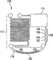
Fig. 1 shows the microfluidic device 10 according to one embodiment of the present invention.As shown in this illustrated embodiment, but equipment 10 comprises two connection units: comprise the substrate 20 of microfluid system 22, and be connected connect substrate two the independently fluid connectors 40 of microfluidic channel.The microfluid system 22 of substrate 20 comprises the passage 24 with entrance 26 and outlet 28 and has entrance 36 and the passage 34 of outlet 38.As shown in the illustrated embodiment of Figure 1A, passage 24 does not connect with being connected; That is to say do not have fluid to be communicated with between passage.As hereinafter more describing in detail, the passage that does not connect may be favourable in some cases, for example in the situation that be used at the different reagent of each passage storage.For example, passage 24 can be used for storing dried reagent and passage 34 can be used for the wet reagent of storage.Make passage each other physics separately can improve the long-time stability of the reagent of storing in each passage, for example with (one or more) reagent of stem body form storage, its impact of avoiding the moisture that may be produced by (one or more) reagent with wet bodily form formula storage is realized by protection.
As shown in the figure, fluid connector 40 comprises the fluid path 42 with entrance 46 and outlet 44.Fluid connector 40 can for example be connected to substrate 20 by entrance and exit.In case connect, fluid path entrance 46 is connected to the outlet 38 of microfluidic channel 34, and fluid path outlet 44 is connected to the outlet 26 of microfluidic channel 24.This connection has caused that between passage 24 and 34, the fluid by fluid path 42 is communicated with.Device and the entrance of substrate with export between be connected and can form Fluid Sealing, to prevent the leakage at the tie point place.Therefore, as shown in Figure 1B, if fluid is mobile along the direction of arrow 56, at least a portion of the fluid in passage 34 can flow in fluid path 42 and flow into subsequently in passage 24 so, alternatively in outlet 28 places outflow.
Although Figure 1A only shows two passages that separate that form microfluid system 22, but in other embodiment, microfluid system can comprise the passage that separates more than two, and fluid connector can be used in three or more such passages that connect substrate.In such embodiment, fluid connector can have several different microfluidic channel that can be connected to substrate a plurality of fluid paths (they can be interconnection or independently) and/or a plurality of entrance and/or outlet.In addition, although Fig. 1 shows in same on-chip two passages that separate 24 and 34, install 40 passages that can be used for connecting on substrates of different.
The microfluid system that forms by two autonomous channels that utilize fluid connector to connect substrate as shown in Figure 1B is an example of " open loop " system.When using in this article, " open loop " System Construction and being arranged to in the situation that the microfluid system inner fluid can not recycle operates.In other words, the fluid section that originates in the primary importance in microfluid system can not pass through primary importance again after it leaves this position.But fluid section can leave in the exit equipment (unless for example fluid section is carried out processing or exhausts in microfluid system).For example, as shown in Figure 1B, can flow into fluid path 42 at position " A " and along the fluid section that the direction of arrow 56 flows at first in and then flow into passage 24, leave at outlet 28 places alternatively; But the design of microfluid system does not allow to flow partly again admission passage 34 also again through position " A ".Similarly, in the position " B " and can leave outlet 28 along the fluid section that the direction of arrow 56 flows at first; This fluid section can not enter into passage 34 or 24 to allow this part again through position " B ".In some cases, microfluid system does not allow fluid to recycle (for example in following use procedure) in system.
In other embodiment, fluid connector can be used in formation " closed loop " system.When using in this article, " closed loop " system can allow fluid to recycle in microfluid system, can again pass through primary importance so that originate in the fluid section of the primary importance in microfluid system after it leaves this position.For example, if second fluid connector (for example fluid connector that is similar to fluid connector 40) is used for connecting entrance 36 and the outlet 28 of Figure 1B substrate 20, just will form closed-loop system.Alternately, if microfluid system 22 is designed to make entrance 36 and outlet 28 to engage so that passage 24 and 34 forms a continuous passage, so fluid connector 40 is connected to entrance 38 and just will forms closed-loop system with outlet 26.
Be also to be understood that the equipment of describing can comprise the fluid connector more than herein.A plurality of fluid connectors are used for connecting a plurality of passages (or various piece of passage) of one or more substrates.
In some embodiments, fluid connector can be used for two (or more) parts of the single microfluidic channel of connection substrate.Should be appreciated that, the place of (independently) passage of opening at least the first and second minutes of substrate is described in this article, fluid connector can be used for connecting similar embodiment, but use fluid connector connect before at least a portion of first passage be communicated with at least a portion fluid of second channel except the situation of (for example to form the passage of an interconnection).
Alternatively, and as hereinafter introducing more in detail like that, fluid connector 40 can comprise at least one the nonfluid feature 52 with feature 54 complementations of substrate, is connected with nonfluid between substrate with formation fluid connector when fluid path connects.This nonfluid connects can help being connected between stabilized fluid connector and substrate.
In some embodiments, fluid connector 40 can be used in one or more fluids (for example sample such as blood, serum, blood plasma, tear, saliva, urine, seminal fluid, phlegm or other interested fluid such as buffer solutions arbitrarily) are incorporated in the microfluid system of substrate 20.This allows sample (or other fluids) to walk around at least one passage of substrate.For example, as shown in Figure 1B, fluid connector 40 is connected to substrate 20 if at first sample is incorporated in fluid path 42 and subsequently, fluid flows along the direction of arrow 56 and flow in passage 24 rather than in passage 34 with regard to the sample that allows to hold in fluid path 42 so.Such design is for will be by the sample that fluid path 42 is carried contaminated or otherwise the situation that can affect undesirably one or more components in passage 34 may be useful.But, should be appreciated that, fluid connector need to be for introduction of fluids in equipment, but can only be used in some embodiments at least two passages of the one or more equipment of fluid ground connection.
As mentioned above, fluid can be incorporated in fluid path 42 by entrance 46 (or export 44, it can be used as entrance for the purpose of introducing fluid).All or part of of fluid path 42 can be equipped with fluid.Alternatively, fluid connector 40 can comprise the second flow path 48, and it is connected to flow path 42 with entrance 50.During this design can allow for example by entrance 50 and the second path 48, fluid to be incorporated into fluid flow path 42 before or after fluid connector has been connected to substrate (for example shown in Figure 1B).Alternately, can by entrance 50, fluid be incorporated into fluid path 42 before connecting fluid connector and substrate.In some embodiments, in by entrance 50 and second fluid path 48, fluid being incorporated into fluid path 42 after, can (for example with plunger or use other suitable methods arbitrarily) with entrance 50 and second fluid path 48 sealings.This sealing can reduce the crossing number of times of passage of microfluid system in the equipment operating process, and may be favourable due to following reason.
In some embodiments, (comprising equipment substrate and fluid connector) described herein microfluid system is before the using first of equipment and/or included the reagent of storage before during sample is incorporated into equipment.The use of institute's storing reagent can be simplified the user to the use of microfluid system, because this makes the quantity of the step that the user must carry out for operating equipment minimize.The microfluid system that this simplification can allow to describe is herein used by unbred user, and for example those real-time tests arrange.Storing reagent in microfluidic device is particularly useful for being designed for the equipment that carries out immunoassays.
Fig. 2 shows the block diagram 60 that can comprise storing reagent and can be used in the microfluidic device that carries out chemistry and/or biological respinse (for example immunoassays).Microfluidic device comprises the reagent entrance 62 that is communicated with reagent storage zone 64 fluids, and reagent storage zone 64 can comprise for example one or more passages and/or one or more container.Equipment can also comprise sample loading area 66, for example reagent storage zone 64 can be connected to the fluid connector of conversion zone 68.The conversion zone that can comprise the one or more zones (for example detection zone) for detection of the component in sample can be communicated with and be coupled to outlet 72 with regional 70 fluids of waste material.In some embodiments, conversion zone 68 is immunoassays zones.
In illustrative embodiments shown in Figure 2, part 80 comprises reagent entrance and reagent storage zone, and part 82 comprises conversion zone, waste material zone and outlet.Reagent can be stored in one or two in part 80 and 82.For example, in a specific embodiment, a kind of reagent is stored in the reagent storage zone 64 of part 80 with the form (for example liquid or gas) of fluid, and the reagent storage of dry film form is in the conversion zone 68 of part 82.
In some embodiments, part 80 and 82 in sample is incorporated into equipment before just (for example by sample loading area 66) each other fluid be communicated with.For example, if sample loading area 66 comprises the fluid connector 40 in Fig. 1, fluid connector just can be connected to substrate to cause part 80 to be communicated with fluid between 82 so.Subsequently, sample can be incorporated in equipment by entrance 50 and second fluid path 48.
In other embodiment, part 80 and 82 in sample is incorporated into equipment before each other not fluid be communicated with.For example, if sample loading area 66 comprises the fluid connector 40 that does not have entrance 50 or second fluid path 48 in Fig. 1, at first fluid connector can be filled with sample and be connected to subsequently substrate that between part 80 and 82, fluid is communicated with to cause so.In this example, when forming fluid being communicated with between part 80 and 82 or the moment after the short time, sample is introduced in the passage of substrate.Under these circumstances, part 80 and 82 is not fluid connection each other before the use first of equipment, wherein when using first, makes the fluid connection each other of these two parts.
As described herein, can be used for one or more reagent of chemistry and/or biological respinse just store before can be before using first and/or in sample is incorporated into equipment and/or be arranged on equipment in (for example in equipment substrate and/or fluid connector).Such reagent can and/or arrange with fluid and/or the storage of stem body form, and the method for storage/setting can depend on concrete application.Reagent can be stored and or be set to for example liquid, gas, gel, a plurality of particle or film.Reagent can be placed in the part of any appropriate of equipment, includes but not limited to be placed in passage, in container, on the surface and in film or on film, and it can be the part in reagent storage zone alternatively.Reagent can be related with microfluid system (or part of system) in any suitable manner.For example, reagent can be crosslinked (for example covalency or ion ground), absorb or absorption (physical absorption) surface in microfluid system on.In a specific embodiment, all or part of of passage (for example passage of the fluid path of fluid connector or equipment substrate) is coated with anti-coagulants (for example heparin).In some cases, before before using first and/or in sample is incorporated into equipment, fluid namely is included in the passage or container of equipment.
In some embodiments, do reagent storage in a part of microfluidic device and in the wet second portion of reagent storage at microfluidic device.Alternately, two of equipment parts of separating can contain dried reagent and/or wet reagent.In some cases, the first and second parts can be before using first and/or in sample be incorporated into equipment before just each other fluid be communicated with.In other cases, two parts before using first and/or in sample is incorporated into equipment before each other not fluid be communicated with.In use procedure first, storing reagent can pass through from a part of equipment another part of the equipment that arrives.For example, the reagent with the fluid form storage can pass through to arrive second portion from first after connecting the first and second parts by fluid path (for example fluid connector).In other cases, as reagent and the fluid hydration of dry matter storage, and when connecting, described part passes through to arrive second portion from first subsequently.And in other cases, as reagent and the fluid hydration of dry matter storage, but can't be from a part by arriving another part after described part connects.The method of following more detailed description storing reagent.
Should be appreciated that, although include only two parts 80 and 82 by the microfluid system of block diagram 60 expressions, microfluidic device can comprise extra part in other embodiments.In addition, the order that flows between reagent storage zone 64, sample loading area 66 and conversion zone 68 of fluid can be different in some equipment.For example, Fluid Flow in A can be by regional from the regional directed response of reagent storage, and then Fluid Flow in A is by regional from sample loading area directed response.Other layout is also possible.
Fig. 3 A-3D shows an example of microfluidic device, and this microfluidic device comprises fluid connector and comprises the storing reagent that can be used in chemistry and/or biological respinse.Equipment 100 comprises first 106, and first 106 comprises reagent storage zone 110, and reagent storage zone 110 is for the form of passage 112 and comprise entrance 116 and export 118.Can according to concrete application with different reagent storage in passage 112.For example, if equipment will be used for carrying out immunoassays, passage can store washing fluid 120, antibody fluid 122, washing fluid 124, labelled antibody fluid 126 and washing fluid 128 therein successively so.Also other reagent and washing fluid can be arranged if need.The form of the plug (for example fluid plug) that the fluid plug 130 that these reagent can be able to not be merged (for example separation of the fluid, such as gas (for example air, nitrogen or argon gas) or oil (for example fluorocarbon or hydrocarbon)) is separated from each other.In Fig. 3 A, entrance 116 and outlet 118 sealed evaporation and pollutions to prevent storing reagent.
Equipment 100 also comprises second portion 150, and second portion 150 has entrance 154, outlet 156, passage 158, conversion zone 160 and waste material zone 174.Conversion zone can comprise several detection zones 162,164,166 and 168.Detection zone can have structure and/or the layout that is fit to arbitrarily.In one embodiment, each detection zone is the form of crooked (wriggling) passage, as the publication number of submitting on April 19th, hereinafter with 2006 be WO2006/113727 (international patent application no is PCT/US06/14853) and name be called introduce more in detail in the international patent application of " Fluidic Structures IncludingMeandering and Wide Channels ", incorporate this patent full content into this paper by reference here.Detection zone can be arranged to the different component for detection of for example sample, perhaps can just be used as and/or negative control.In some cases, the one or more reagent that are stored in wherein that comprise in detection zone.In a specific embodiment, comprise the dried reagent of a series of storages for the equipment that carries out immunoassays.Reagent can physical absorption to the surface of bending channel.For example, detection zone 162 can comprise negative control (for example known cleaning agent be used to preventing protein attachment), detection zone 164 and 166 can comprise the antibody that can adhere to the component in sample (or two kinds of different antibody that can adhere to different component in sample) of variable concentrations, and detection zone 168 can comprise positive control (for example wishing same antigen definite from sample).Positive control can be used as qualitative control; For example, if signal reaches certain threshold value, it is effective that test can be considered to.Additionally and/or alternately, positive control also can be used as quantitative tool; For example, signal strength signal intensity can be the part of sheet internal calibration process.
As shown in the embodiment shown in Fig. 3 A, each zone in part 150 fluid each other is communicated with, but all is not communicated with the arbitrary portion fluid of part 106.In some embodiments, the part 106 that comprises the part 150 of storing dried reagent and comprise the wet reagent of storage was configured to before using first each other not that fluid is communicated with, and reason is that this structure can promote each reagent in its longer-term storage in part separately as hereinafter further introducing.
As shown in Fig. 3 B, part 106 can use fluid connector 178 to connect with being connected, and causes part 106 and 150 fluid connection each other.If export 118 and entrance 154 covered by seal (for example biocompatible adhesive tape) in Fig. 3 A, should connection can make the sealing on outlet and entrance be pierced, destroy or remove so.
Fluid connector 178 can be used for sample and load, and can comprise the sample 180 that is included in wherein.As described herein, sample 180 can be introduced in fluid connector 178 by suitable method, and in some cases, is introduced in fluid connector before fluid is communicated with between part 106 and 150.
As shown in the embodiment shown in Fig. 3 C, the fluid in reagent storage zone 110 and sample 180 can be from part 106 to part 150 flow.Fluid Flow in A can be for example by applying normal pressure (for example using plunger, gravity or pump) to entrance 116 or by using vacuum sources and occur exporting 156.In such embodiment, positive pressure sources and/or vacuum source can be connected to respectively one or more entrances and/or outlet.
At first sample 180 flow into (Fig. 3 C) in conversion zone 160, and flow into subsequently in waste material zone 174 (Fig. 3 D).Sample from detection zone through one or more components (for example antigen) of allowing sample and interaction (for example being combined) between one or more components (for example antibody) conversion zone.As described herein, (one or more) component of conversion zone can be the form of the dried reagent just be stored in conversion zone before using first in.This interaction can form for example in conjunction with the product to complex compound.In some cases, only this interaction self is determined (for example measuring) signal with regard to causing by the detector that is coupled to microfluid system.In other cases, determine signal accurately in order to make detector, product is used from one or more reagent in reagent storage zone 110 and is processed.For example, being stored in reagent in reagent storage zone 110 can be labelled antibody with the AI of sample.This interaction can allow product is carried out mark or strengthens signal from product.
In a specific implementations that relates to immunoassays, the storing reagent in storage area comprise enzyme strengthen liquid and lake (diaminobenzidine for example, DAB).One or more reagent from reagent storage zone 110 are allowed through each detection zone.These reagent can be further with in conjunction with complex compound is interacted, for example strengthening signal and/or mark complex compound, as shown in the detection zone 164 and 168 of Fig. 3 D.
By keeping the fluid (separate fluid) that can not merge between each reagent in the reagent storage zone, the fluid of storing can sequentially be carried from the reagent storage zone, the contact in the fluid of avoiding simultaneously storing between any fluid.The fluid that can not merge of any separately institute's storing reagent can be applied to conversion zone and not change the condition of conversion zone.For example, if the combination of antibody-antigen has occured at one of them detection zone of conversion zone, can locate application of air to this so, only have minimum impact or basic not impact for any combination that has occured.
As described herein, the storing reagent in microfluid system can allow to be used for specific order-assigned reagent the processing (for example strengthening the signal at conversion zone) in downstream.In the situation that expectation exposes special time with reagent, in microfluid system, the amount of each fluid can be exposed to the time quantum in downstream reaction zone proportional with reagent.For example, if be that in passage, the amount of the first reagent can be just the twice of the amount of the second reagent in passage so for the twice of expectation open-assembly time of the second reagent for expectation open-assembly time of the first reagent.If make reagent apply constant pressure reduction in from the channel flow to the conversion zone, and if the viscosity of fluid is identical or similar, so every kind of fluid can be proportional with the relative volume of fluid in the open-assembly time that particular location (for example conversion zone) is located.Various factors (for example geometry of passage, pressure or viscosity) also can change, to change the flow velocity from the concrete fluid of passage.
In addition, in order storing reagent particularly this strategy of Contrast agent can be applicable to the chemical reaction of wide scope.For example, produce optical signalling (for example absorbance, fluorescence, aura or chemical flash, electrochemical luminescence), the signal of telecommunication resistance or the electrical conductivity of the metal structure that generates without electric process (for example by) or the various enhancing chemical reactions of magnetic signal (magnetic bead) and can be used in permission by the detector detection signal.
Reagent needs whole microfluidic device compatible with a lot of bubbles to use gas (for example air) plug to come separately.In microfluidic device, bubble stablized and/or controlled although can make ins all sorts of ways, a kind of ad hoc approach that uses in some embodiment of describing in this article comprises the quantity of passage joining in restriction system.Therefore, the microfluidic device of describing herein can be designed as to have a small amount of (for example, being less than 5,4,3 or 2), a joining or there is no the passage joining.As used in this article, passage intersects and comprises at least three passages (perhaps a plurality of parts of one or more passages) (for example consisting of " Y ") that intersect at a point.For example, the equipment 100 in Fig. 3 does not have any passage joining, and 200 of the equipment in Fig. 4 have a passage joining 219.The equipment that does not have any passage joining may be for example useful for not needing the reaction of mix reagent (for example storing reagent).
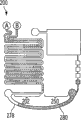
Fig. 4 A-4D shows another example of microfluidic device, and this microfluidic device comprises fluid connector and comprises the storing reagent that can be used in chemistry and/or biological respinse.As shown in embodiment as illustrative in these, equipment 200 comprises first 202, and first 202 comprises reagent storage zone 204.The reagent storage zone has two parts: top 205 and bottom 206.Top comprises passage 208 and passage 209, and passage 208 has connected entrance 216, and passage 209 has connected entrance 217.Passage 208 and 209 in top be separately and join at joining 219 places, it is connected to the passage 212 of bottom.Passage 212 is connected to outlet 218.But equipment 200 with two entrances 216 and 217 (each entrance is connected to different passages) may be for example be used for carrying out wherein two kinds of reagent and need to be stored in dividually on equipment needs in use or the reaction that just mixes before use is useful.
In a specific embodiment, equipment 200 is used for carrying out the immunoassays to human immunoglobulin(HIg), and it uses silver-colored intensive to be used for the signal enhancing.Silver salt solution is stored in passage 208, and hydroquinone solution is stored in passage 209.Because these the two kinds components that can cause signal to strengthen when mixing are arranged in passage separately, so until these two kinds of flow of solution of flow driving they just can be mixed with each other to joining 219.
The reagent that needn't merge each other can be stored in the bottom 206 in reagent storage zone.These reagent can comprise for example fluid of washing fluid, antibody fluid and other needs.Reagent can be the form of the plug that is separated from each other by the fluid plug 230 that can not merge (for example separate fluid, such as gas (for example air) or oils).In Fig. 4 A, entrance 216 and 217 and export 218 sealed evaporation and pollutions to prevent storing reagent.
Equipment 200 also comprises second portion 250, and second portion 250 has entrance 254, outlet 256, passage 258, conversion zone 260 and waste material zone 274.Conversion zone can comprise several detection zones 262,264,266 and 268.Alternatively, one or more detection zones can be the forms in bending channel zone as described in this article.Detection zone can be arranged to the different component in order to test example such as sample, perhaps just is being used as and/or negative control.In some cases, one or more detection zones comprise the reagent that is stored in wherein.In one embodiment, the dried reagent that comprises a series of storages for the equipment that carries out immunoassays.Reagent can physical absorption to the surface of the bending channel of detection zone.
in a specific embodiment, wherein equipment 200 is used for execution to the immunoassays of human immunoglobulin(HIg) and uses silver-colored intensive to be used for signal strengthening, one or more surfaces of the bending channel of conversion zone are with biomolecule for example BSA (bovine serum albumin) or tween, negative control (for example known cleaning agent be used to preventing protein adsorption), can be incorporated into antibody (for example human immunoglobulin(HIg) antibody) and the human immunoglobulin(HIg) of the variable concentrations of component in sample, modification is carried out in positive control (for example wishing from the definite same antigen of sample).These reagent were stored in 250 parts by sealed entry 254 and outlet 256 before using in.
As shown in Fig. 4 B, part 202 can use fluid connector 278 to connect with being connected, and makes part 202 and 250 fluid connection each other.Fluid connector 278 can be used for sample and loads and can comprise the sample 280 (for example blood) that is included in wherein.As described herein, sample 280 can be introduced in fluid connector 278 by suitable method, and in some cases, is introduced in fluid connector before fluid is communicated with between part 202 and 250.
As shown in the embodiment shown in Fig. 4 C, the fluid in reagent storage zone 204 and sample 280 can flow to part 250.Fluid Flow in A can be for example apply normal pressure by (for example using plunger, gravity or pump) to entrance 216 and 217 or by using vacuum and produce exporting 256.At first sample 280 flow into (Fig. 4 C) in conversion zone 260, and flow into subsequently in waste material zone 274 (Fig. 4 D).One or more component interactions (for example being combined) that sample is stored with conversion zone by one or more components that allow sample from detection zone.This interaction can form product for example in conjunction with to complex compound.The fluid mobile enhancing that can cause mark and/or the signal of product on detection zone subsequently from the reagent storage zone.
In a specific embodiment, equipment 200 is used for execution to the immunoassays of human immunoglobulin(HIg) and uses silver-colored intensive to be used for signal strengthening.After the sample that will comprise human immunoglobulin(HIg) was delivered to conversion zone from fluid connector, dried reagent, the combination between human immunoglobulin(HIg) antibody of human immunoglobulin(HIg) and storage will be carried out.This combination can form combination to complex compound in detection zone.Then can flow on to complex compound in this combination from the storing reagent of the bottom 206 in reagent storage zone 204.A kind of in storing reagent can comprise metallic colloid (for example golden conjugated antibodies) solution that specifically is bonded to detection antibody (for example human immunoglobulin(HIg)).This metallic colloid can for opaque material for example metal (for example silver) layer provide catalytic surface in the lip-deep deposition of detection zone.This metal level can form by using two-component system as above: can be stored in the metal precursor (for example silver salt solution) in passage 208, and can be stored in the reducing agent (for example quinhydrones) in passage 209.Owing to having applied plus or minus pressure reduction to system, so silver salt and hydroquinone solution are finally converged at joining 219 places, they mix along passage 212 (for example due to diffusion) lentamente at this, then flow on conversion zone.Therefore, if antibody-antigen combination has occured in conversion zone, metal precursor solutions flows through this zone and just can cause due to the existence with antibody-catalytic metal colloid that the antigen complex compound is associated for example formation of silver layer of opaque layer so.Opaque layer can comprise the material of the projection ratio of the light that disturbs one or more wavelength.Any opaque layer that forms in microfluidic channel can detect optically, for example carries out with the reduction of the light transmittance of comparing the part (passage of for example meandering) by conversion zone by the part that does not comprise antibody or antigen in zone by measuring.Therefore alternately, because forming film in detection zone, can come picked up signal by the variation of measuring as the light transmittance of the function of time.Compare with the technology that does not form opaque layer, opaque layer can provide the raising of measuring sensitivity.
Fig. 5 A-5F shows the image for the equipment that carries out the human immunoglobulin(HIg) immunoassays according to one embodiment of the present invention, and will partly be further described in more detail in example.
Although mainly described immunoassays, but should be appreciated that herein the equipment of describing can be used for chemistry and/or the biological respinse that is fit to arbitrarily, and for example can comprise other the Solid-phase Assay that relates to the affinity reaction between the molecule that protein or other biological molecule (for example DNA, RNA, carbohydrate) or non-natural exists.
And, use fluid connector to connect two parts of two passages or passage although a lot of embodiments of describing comprise herein, embodiment herein also comprises and does not use fluid connector and sample is incorporated into apparatus and method in microfluid system.For example, in some embodiments, open-ended fluid device (namely only having an end to be connected to the equipment of microfluid system) can be used for sample is incorporated into microfluid system.
Fig. 6 shows the block diagram 560 with the microfluidic device that uses the open-ended hardware compatibility of introducing for sample.Microfluidic device can comprise storing reagent, and can be used in and carry out chemistry and/or biological respinse (for example immunoassays).Microfluidic device comprises the reagent entrance 562 that is communicated with reagent storage zone 564 fluids, and reagent storage zone 564 can comprise for example one or more passages and/or one or more container.Equipment can also comprise sample entrance 565, sample loading area 566 and conversion zone 568.Can comprise for detection of the conversion zone in one or more zones of component in sample and can be communicated with waste material zone 570 fluids, and can be coupled to and export 572.In some embodiments, conversion zone 568 is immunoassays zones.
Fig. 7 A-7D shows the example with microfluid system of feature described in Fig. 6.Microfluid system 590 and the open-ended fluid device compatibility that is used for sample is incorporated into system.In Fig. 7 A, fluid reagent is stored in reagent storage zone 564 and does reagent storage in conversion zone 568. Entrance 562 and 565 and export 572 sealed before use.As shown in the embodiment shown in Fig. 7 B, seal on sample entrance 565 can be pierced, removes or destroy to allow sample 592 is incorporated in sample entrance 565, sample can flow in sample loading area 566, and this sample loading area 566 can comprise empty bending channel 594.Flowing of sample can occur by capillary force at first.Alternatively, seal can be arranged on sample entrance 565, and can be with vacuum application in exporting 572 to impel the Fluid Flow in A (Fig. 7 C) towards outlet.Sample flow in conversion zone 568, is the storing fluid reagent from reagent storage zone 564 subsequently.As shown in Fig. 7 D, all by after conversion zone, they can be accommodated in waste material zone 570 (perhaps can leave equipment via outlet alternatively) at all reagent.
As described herein, for example open-ended fluid device and/or fluid connector are incorporated into fluid (for example sample) in microfluidic device can to use various device.Although several structures of these equipment have been shown in Fig. 8-13, should be appreciated that the present invention is not limited to these structures, other structure and/or layout are also possible.In addition, although relate to herein sample introduce assembly (for example open-ended fluid device and fluid connector) the description article sample is incorporated into the microfluid substrate, but these assemblies also can be used in the material of guiding any appropriate, for example the reagent component of system (for example buffer, reinforcing agent, two-part), gas and particle.
For the equipment of middle use is set at real-time test, sample is introduced assembly and can be designed for protecting the user to avoid occupational disease.In addition, the complexity of sample process step can be minimized to allow use equipment outside the medical laboratory.When selecting to be used for the specific design of sample introducing assembly, can consider these factors.
For example the sample of open-ended fluid device and fluid connector is introduced the object that assembly can comprise any appropriate, and this object has the fluid path that is arranged on wherein.Sample is introduced assembly (and other passages of microfluid system) can have internal diameter always or variable, and for example can have greater than 10 to 1, greater than 50 to 1 or greater than 100 to 1 length-internal diameter ratio.According to application, can use the sample with arbitrary diameter to introduce assembly (or microfluidic channel), and in a lot of the application its for example can have less than 1cm, less than 5mm, less than 1mm, less than 500 microns, less than 200 microns, less than 100 microns or less than the internal diameter of 50 microns.Have when introducing in the amount of every kind of fluid that assembly (or microfluidic channel) may comprise in indication component (or microfluidic channel) visually than the sample of big-length-internal diameter ratio useful.For example, can provide the volume of fluid or the accurate indication of relative volume to fluid device with known internal diameter or the linear measurement of the fluid plug in fluid connector.In some embodiments, sample introducing assembly comprises pipe.Can obtain at an easy rate the pipe of different-diameter, length and material.Pipe can be flexible and can be translucent or transparent.Fluid plug in pipe can be by the indication of linear measurement as the volume of plug.
Sample is introduced assembly, if pipe or other shapes can comprise two or more branch roads or part, they can be communicated with each other and with remaining interior section fluid of assembly.In some embodiments, pipe can have two, three, four or the more branch road that can interconnect.Branch road and branch road crosspoint can comprise valve, perhaps do not comprise valve.Valve can be used for temporarily one or more branch roads and any fluid of being included in are wherein isolated with the remainder of pipe.
In some embodiments, for example the sample of open-ended fluid device or fluid connector introducing assembly comprises the volume control element.The volume control element can allow the fluid filling sample introduce assembly fluid path a part but be not all in.The volume control element can be used in metering for introduction into the concrete volume of the fluid in microfluid system.In one embodiment, the volume control element is frit (frit), and it can be arranged on sample and introduce in the fluid path of assembly and be introduced in fluid path to stop more fluid after fluid reaches designated volume.The volume that sample is introduced the fluid (for example sample) in assembly can be defined by the volume of the inlet point (for example entrance) that is used for the introducing fluid and the fluid path between frit; Remaining volume can be occupied by air.
In another embodiment, the volume control element comprises one or more gage marks, and its indication fluid is introduced in (one or more) point that should reach in fluid path.The volume of the fluid in fluid path can be controlled by the user.
And in another embodiment, the volume control element comprises that sample introduces the change (for example broadening) on the diameter of the fluid path in assembly.For example, open-ended fluid device or fluid connector can comprise first end (for example opening), have the fluid path of the first diameter first, have the second portion of the fluid path of Second bobbin diameter, then be the second end (for example opening).Second bobbin diameter can be greater than the first diameter.The first diameter can help by capillary force, fluid to be flow in fluid path, and Second bobbin diameter can lessly help (perhaps being unsuitable for) capillarity.Therefore, fluid can enter via first end the first of fluid path, and fluid can stop entering fluid path when it arrives the second portion of fluid path.In the present embodiment, sample introduce the volume of the fluid (for example sample) in assembly can be by the volume definition of the first of fluid path; Remaining volume (for example second portion of fluid path) can be occupied by air.Those of ordinary skills know that how to confirm helps or the less diameter that helps capillary fluid path.
In another embodiment, the volume control element is included in the interior patterned surface of fluid path that sample is introduced assembly.For example, sample introduce assembly can comprise first end (for example opening), have the fluid path of the first hydrophilic surface first, have the second portion of the fluid path of the second hydrophobic surface, then be the second end (for example opening).The first hydrophilic surface can flow in fluid path hydrophylic fluids (for example aqueous fluid) via capillary force, and the less capillarity that helps of the second hydrophobic surface.Therefore, fluid can enter via first end the first of fluid path, and fluid can stop entering fluid path when it arrives the second portion of fluid path.In the present embodiment, sample introduce the volume of the fluid (for example sample) in assembly can be by the volume definition of the first of fluid path; Remaining volume (for example second portion of fluid path) can be occupied by air.In a specific embodiment, the hydrophilic segment of fluid path is by anti-coagulants (heparin, chelating agent (ethylenediamine tetra-acetic acid for example for example, EDTA) or citrate) existence definition, and there is not (or existence of one or more hydrophobic molecules) definition in the hydrophobic part of fluid path by anti-coagulants.Method and material for the patterned surface that makes fluid path are known to a person of ordinary skill in the art.
In some embodiments, for example the sample of open-ended fluid device or fluid connector introducing assembly can comprise for example combination of the volume control element of above-mentioned various volume control elements.Can use the method for any appropriate, for example by capillary force, use vacuum, apply malleation and introduce assembly by fill the sample that comprises one or more volume control elements with valve.
As hereinafter introducing more in detail, can make ins all sorts of ways introduces assembly with sample and is connected to substrate.For example, sample is introduced assembly and/or substrate and can be comprised following one or more: pressure assembly parts, friction fit part, threaded connector (for example Screw assembly spare), snap-fit part, bonding assembly parts, clip, magnetic coupling or other suitable mechanisms that is coupled.
Fig. 8 A shows an example of open-ended capillary 700 (for example open-ended fluid device), and it can be used in sample is incorporated in the entrance (for example sample entrance 565 in Fig. 7 A) of equipment.Pipe 700 can have openend 704 (entrance that for example is used for the equipment that is inserted into); End 702 can opening or sealing.As shown in Fig. 8 B, capillary 710 also can be as fluid connector with for example in conjunction with two passages (or each several part of passage) of the described connection microfluid system of Fig. 3.Pipe 710 can comprise openend 712 and 714.Crooked is to can be used in to connect a kind of in may equipment of two passages (or each several part of passage) multiple with the use capillaceous that forms " U " shape.
Equipment in Fig. 8 A and 8B can be made and can is rigidity or flexibility by the material (for example polymer or pottery) of any appropriate.The non-limiting example of these materials comprises glass, crystal, silicon, polytetrafluoroethylene (PTFE) (special teflon), polyethylene, Merlon, polyethylene (dimethyl silicone polymer), PMMA, polystyrene, cyclic olefine copolymer (COC) and cyclic olefin polymer (COP).In some embodiment that pipe is made by flexible material therein, pipe can be placed in the fixator of being made by the material of enough rigidity pipe is remained on its net shape.For example, as shown in the embodiment shown in Fig. 8 C, pipe 720 can be placed in the groove 732 of fixator 730 shape with holding tube.Alternatively, lid 734 can be used for covering fixator and can be for example by sealing, gummed, in conjunction with, use adhesive or be attached to fixator by mechanical attachment (for example being clamped to fixator).In other embodiment, replacement is placed in pipe in groove, and fixator can comprise the protruding features (for example clip) for stationary pipes.One or more passages (Fig. 8 D) of microfluid system can be exposed to allow to be connected in end 722 and 724.
In another embodiment, the part of open-ended fluid device (for example capillary) or fluid connector can be made by the flexiplast that radiation-sensitive materials for example hardens when being exposed to heat or ultraviolet light.Equipment is folding or bend to intended shape (for example " U " shape) after, be exposed to and can make capillary keep its new shape in suitable radiation.
In another embodiment, replace straight capillary bending is designed with the formation U-shaped, open-ended fluid device or fluid connector can directly manufacture its net shape.An example comprises by glass blowing being the capillary of curved shape, its can allow to be loaded into sample on microfluidic device and/or between passage or the fluid between the each several part of passage connect.Also can use other process technology and material, comprise injection molding or extrusion molding.
As shown in the embodiment shown in Fig. 9 A-9F, the one- block apparatus 800 and 830 with microscler volume (for example the microchannel 804) of hollow can be used as fluid connector.Described equipment can be rigidity (for example being used for avoiding the requirement of user's tortuous capillary), and can comprise alternatively that handle is used for shirtsleeve operation (for example side handle 812 shown in the vertical handle 810 shown in Fig. 9 B or Fig. 9 E).In such embodiment, the loop of U-shaped pipe capillaceous can be replaced by the microchannel with any suitable size 804 that forms in substrate 816.The size of microchannel can regulate to hold the fluid (for example 1-1000 μ L) of wider range volume.Such equipment can be filled fluid (for example sample) fully or can partly be filled with fluid (for example using the volume control element with the amount of the fluid in the meter fluid path).And the size of microchannel also can be chosen to utilize capillary force that fluid is introduced passage for allowing, and perhaps alternately, fluid can utilize vacuum to be inhaled into.
Passage can be covered by lid (for example lid 820 and 822), and lid can be for example block, adhesive film or adhesive tape.The equipment that represents in Fig. 9 A-9C may be between lid 820 and substrate 816 integrating step (for example by using adhesive).In some embodiments, such geometry step can be avoided (Fig. 9 D-9F) by the lid 822 of application examples such as adhesive film (or adhesive tape) on the surface of equipment.
As shown in Fig. 9 A and 9D, equipment 800 and 830 can comprise turnover port 806 and 808 (for example entrance and exit), and it can allow fluid to be introduced in fluid path and/or make between the passage of microfluid system (or each several part of passage) and can be communicated with by fluid.The turnover port can have the shape of any appropriate to allow to form the tight seal to the port of microfluid system.As shown in Figure 9 shown in embodiment, port can have the conical in shape with the bellmouth complementation of microfluidic device.
In some embodiments, in case fluid connector is connected to microfluidic device (for example equipment shown in Fig. 1,3 and 4), just the outlet of equipment applied vacuum to cause the Fluid Flow in A in system.In these embodiments, vacuum can be strengthened the airtight quality between complementary port.
Another example of fluid connector has been shown in Figure 10 A and 10B.In the embodiment shown in Figure 10 A and 10B, fluid connector 852 is by assembling 850 preparations of two parts.Fluid connector 852 shows the fluid path 855 in rigid substrate 858 interior realizations, but in other embodiment, geometry can be used arbitrarily, comprises the structure of bending channel.Entrance 862 and outlet 864 can be that the part of pyramidal projections 865 is to form gas-tight seal together with the bellmouth of microfluid sheet.As hereinafter more describing in detail, can realize more accurate connected system, for example snap fastener or non-taper assembly parts.If necessary, fluid connector can be optimized to allow the easy operation of user (be included in and add handle in design).
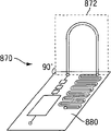
In embodiments more as herein described, by the port of fluid connector being inserted the manhole appendix directly over (one or more) microchannel that is arranged in substrate, fluid connector is connected to microfluidic device (for example comprising the substrate that is arranged on microfluidic channel wherein).As a result, the fluid path of fluid connector can be in plane perpendicular to the plane, microchannel of substrate, as shown in Figure 11 A.But, in some applications, advantageously fluid connector is placed in the plane identical with the microchannel network and (for example uses the side to connect).An advantage of this structure can be to allow to maximize for the area of observing microfluidic device (for example being used for highly parallel mensuration).Another advantage can be to allow large number quipments to be stacked on each other top separately, allows simultaneously each equipment can both connect in fluid distributor or other instruments, so just can save the memory space in instrument.In such embodiment, fluid connector 872 can be connected to the end sections 876 of substrate 880.In other cases, fluid connector can with 90 to 180 the degree between or 0 to 90 the degree between angle be connected to substrate.Therefore, the fluid connector of describing herein can be connected to substrate with the structure of any appropriate.
The reliability and the simplicity that form the sealing of good (for example fluid-tight) between fluid connector and microfluid substrate are the design aspect of a key of equipment for the equipment that middle use is set at real-time test.In this respect, fluid connector or substrate self can comprise that supplementary features are to help the user that equipment is inserted on the microfluid substrate or is inserted in the microfluid substrate.For example, in one embodiment, fluid connector comprises at least one the nonfluid feature with the feature complementary of substrate, to be connected with nonfluid between substrate namely forming fluid connector after connection.The nonfluid complementary characteristic can be the protrusion features of for example fluid connector and the respective complementary cavity of microfluid substrate, and it can help the user with fluid connector and substrate alignment.And these guide features can also help equipment is remained on the appropriate location.In other cases, substrate comprises the protrusion features with the cavity complementation of fluid connector.In another embodiment, equipment comprises alignment element, the predetermined setting structure that this alignment element is associated with substrate and is constructed and arranged to be in respect to substrate for engaging with fluid connector and thus connector being placed in.The example of these and other feature shall be described in more detail below.
Thereby Figure 12 A-12E shows and can fluid connector be attached to the embodiment of microfluid substrate by two assemblies being fastened togather form connection.This structure may be useful especially for the application that relates to care diagnostic, and reason is that snap fastener can make and can be good at sealing between assembly, and can reduce the probability that user's mistake is processed diagnostic test.The noise that the user experiences in fluid connector is engaged to substrate time the and/or sensation can be with the guiding that acts on successfully coupling assembly or controls.
As shown in Figure 12 A, fluid connector 900 can comprise two identical firsts 910 (only showing), namely forms fluid path 912 after with two half ground closures that abut against each other.In other cases, fluid connector comprises single integral piece, and it comprises the fluid path 912 that is arranged on wherein.The end sections 916 and 918 of fluid path (for example entrance and exit) can be attached to microfluid substrate (not shown) via feature 922 and 924, feature 922 and 924 can with the feature complementary of substrate.Fluid connector can also comprise for the opening 930 that inserts clip 934.Clip can comprise two or more snap features (for example sawtooth) 936 and 938; These features can be made and can be by making with clip and/or the identical or different material of substrate by the material (for example polymer) of any appropriate.Feature 938 can be used for clip is connected to first 910, and feature 936 can be used for clip is connected to the microfluid substrate.This feature can allow clip irreversibly is attached to fluid connector and/or substrate.Figure 12 B shows the zoomed-in view of clip.In other embodiment, fluid connector can manufacture has snap feature, and it can be directly a part of 910; For example, fluid connector can comprise feature 936 and not use clip 934 (not shown).
As shown in the embodiment shown in Figure 12 C, in case clip is inserted into (for example when feature 938 is met opening 930-B) in opening 930, clip can be attached to the part 910 of fluid connector.Equally, as shown in Figure 12 D, fluid connector can be inserted in the part of microfluid substrate 940 so that fluid connector is connected to substrate (Fig. 9 E).Snap feature can be directed to fluid connector the tram in the microfluid substrate.As hereinafter introducing more in detail, fluid connector can be reversible or irreversible to the connection of substrate.This connection can make being communicated with via fluid path 912 fluids of substrate between the first passage at 942 places, position and the second channel at 944 places, position of substrate (or part of first passage).As described herein, fluid connector can be loaded into sample (for example by end sections 916 or 918) before or after connecting.
Substitute as a kind of of the snap fastener of describing in conjunction with Figure 12 A-12E, can use zip mode mechanism as shown in Figure 13 that fluid connector is attached to the microfluid substrate.The assembly 955 that comprises feature 956 (for example projection) has been shown in Figure 13, this feature 956 and part 960 complementations, part 960 comprises feature 962 (for example recess).Assembly 955 can be the part of fluid connector and part 960 can be the part of microfluid substrate.In some cases, assembly 955 comprises the fluid path 958 that is arranged on wherein.
Although described with reference to fluid connector and substrate the feature that is used for jockey and substrate, for example in those features shown in Fig. 9,10,12 and 13, these features also can be used for other devices of connection device.For example, these features can be used for connect for example assembly of open-ended fluid device and a plurality of substrate layers of substrate, substrate and lid and/or equipment.
Relating to of describing in this article, comprise in embodiment with the device (for example fluid connector) of at least one feature of the feature complementary of substrate, and these features can be designed for forming reversible connection the between device and substrate.Such embodiment may be useful for for example reusable equipment.In other embodiment, these complementary characteristics form irreversible connection the between devices and substrate.Irreversible connection can make device be connected with substrate to connect.When using in this article, term " integratedly connect " when relating to two or more object, refers to that object can not become be separated from each other in the normal process of using, for example can not manually be separated; Separately need at least tool using, and/or by at least one in assembly caused damage, for example by destroying, piercing through or separate the assembly that tightens together with adhesive or instrument and could realize.The equipment that comprises the feature that forms irreversible connection may be useful for for example disposable (for example can abandon) equipment.Such equipment can form irreversible connection, makes the user just can not disturb chemistry and/or the biological respinse that carries out in equipment after connecting.
Example shown in Figure 12 and Figure 13 comprises be connected (for example fluid or nonfluid connect) more than two between fluid connector and microfluid substrate.This specific character may be useful, and reason is that extra connection (for example nonfluid connection) point can increase the stability that connects opposing mechanical stress (for example due to user's processing produce) and impact (for example the use of the mistake of equipment causes).In addition, each extra interface can both increase the contact area between fluid connector and substrate, and with form the area that fluid connector is associated with Fluid Sealing between substrate and still can remain unchanged.Alternately, a nonfluid connects and may be enough to produce good sealing property.
Although a lot of embodiments of describing all comprise the sample with single fluid path and introduce assembly (for example fluid connector), should be appreciated that sample introducing assembly can comprise more than the fluid path of and/or the fluid path of branch herein.For example, as shown in the embodiment shown in Figure 12 E, fluid connector 900 can comprise second fluid path 946 alternatively, and it is connected to flow path 912 with entrance 947.This design can allow for example via entrance 947 and the second path 946, fluid to be incorporated in fluid flow path 912 after fluid connector 900 has been connected to substrate.Alternately, fluid can fluid connector be introduced in body path 912 before substrate is connected via entrance 947.
In addition, sample introduce the assembly example as described in this article fluid connector can comprise one or more sampling elements for receiving from the fluid sample of biological entities.Sampling element can be the form of pin or swab for example.Sampling element can be reversibly or irreversibly is attached to sample and introduces assembly.In some cases, sampling element can puncture biological part.For example, as shown in the embodiment shown in Figure 12 E, fluid connector 900 can comprise (having sterilized) sampling element 948, the cuspidated form of the tool of hollow (for example pin) for example, and it can be used for puncturing for example part of human body skin.This structure can allow sampling element partly to receive fluid sample from biology, and fluid can be delivered to fluid path 912 (for example passing through capillary force) from biological entities.After fluid has been introduced in entrance 947, can for example utilize assembly 949 sealing second fluid path 946, assembly 949 can have the shape with fluid path 946 complementations.This sealing can prevent that fluid from entering the second fluid path again so that only have a fluid path to be used for flowing.This layout can also prevent that the user further is exposed to sampling element 948.
In another embodiment, assembly 949 (comprising alternatively fluid path) can be used in and obtains sample, and after assembly is inserted in second fluid path 946, and sample can be from component transfer to fluid path 912.In some embodiments, the insertion of assembly prevents that fluid from entering the second fluid path again so that only have a fluid path to be used for flowing.
In some embodiments, sample introducing assembly comprises the sampling element that is attached directly to primary fluid pathway.For example, in the embodiment shown in Figure 10, can comprise in the end sampling element that can allow to puncture biological part with the pyramidal projections 865 of the feature complementary of microfluid substrate.Sampling element also can be used as the part of open-ended fluid device (for example shown in Fig. 8 A) and/or the part of other fluid connectors (for example Fig. 8 B) of describing herein.
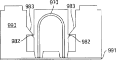
The equipment of describing herein can comprise the alignment element that is associated with substrate alternatively.Alignment element can be constructed and arranged in order to engage and thus fluid connector to be placed in the predetermined setting structure with respect to substrate with fluid connector.As shown in the embodiment shown in Figure 14 A and Figure 14 B, equipment 964 can comprise substrate 966, fluid connector 968 and alignment element 980.Substrate 966 can comprise microfluid system, and example is as described in this article for example at the microfluid system shown in Fig. 1-7,11,17-18.Microfluid system can comprise for example the first microfluidic channel and the second microfluidic channel at least, and the first microfluidic channel includes an inlet and an outlet, the second microfluidic channel (not shown) that includes an inlet and an outlet.Fluid connector 968 can have and constructs as described herein and can be configured for and be complementary to being connected of substrate.Fluid connector can comprise fluid path 970, and fluid path 970 has fluid path entrance 972 and fluid path outlet 974.After fluid connector was communicated to substrate, the fluid path entrance can be connected to the outlet of the first microfluidic channel of substrate, and fluid path outlet 974 can be connected to the entrance of the second microfluidic channel of substrate.This connection can cause the fluid between the first and second microfluidic channel of substrate to be communicated with.
As shown in the embodiment shown in Figure 14 A and 14B, equipment can comprise the alignment element 980 that is associated with substrate and is approximately perpendicular to the substrate extension.For example, when substrate 966 (and first and second microfluidic channel) was located in the plane that defines between arrow 975 and 977 substantially, alignment element 980 extended in the planes by arrow 975 and 976 definition perpendicular to substrate substantially.In other embodiment, alignment element can almost be parallel to substrate and extend.
As shown in the figure, alignment element 980 comprises cavity 981, and cavity 981 is constructed with becoming in order to receive and to engage fluid connector and thus connector to be placed in respect to the predetermined setting of substrate and constructed.Cavity for example can have 0.5cm at least, 1cm, 1.5cm, 2cm or the degree of depth of 3cm (for example measuring from the position that fluid path entrance and/or fluid path export) at least at least at least at least after fluid connector and alignment element engage.Cavity can have the degree of depth that is similar to or equals the fluid connector height.Cavity not necessarily must surround all sides of fluid connector, needs only it and is constructed and arranged to construct in order to receive and to engage fluid connector and thus connector to be placed in respect to the predetermined setting of substrate.
In some embodiments, the structure of alignment element and fluid connector can be suitable for allowing by sliding motion, fluid connector to be inserted in alignment element.For example, in the time of in fluid connector is inserted into alignment element, fluid connector can be against one or more surface slidings of alignment element.
Alignment element can have the structure for any appropriate that engages fluid connector.In some embodiments, alignment element (or cavity of alignment element) can be after engaging for example surperficial 984,985,986 and/or 987 contacts with 1,2,3,4 of fluid connector or more surface.The one or more surfaces that contact with fluid connector of alignment element can from substrate for example along on the plane of definition between arrow 976 and 977, the plane of definition between arrow 976 and 975 and the plane that defines between the two extend.
In addition, for example can have may be more than or equal to height, thickness or the degree of depth (for example being used for inserting fluid connector) of at least 1 times, 2 times, 3 times, 4 times, 5 times equimultiple of the thickness 979 of substrate for all or part of of alignment element.Alignment element for example can have 0.5cm at least, 1cm, 1.5cm, 2cm or the height of 3cm or thickness (for example measuring from the position that fluid path entrance and/or fluid path export) at least at least at least at least after fluid connector and alignment element engage.In some embodiments, the larger height/thickness of alignment element can allow further to stablize and/or guide fluid connector to enter into alignment element.Size can change and can depend on many factors, for example the size of fluid connector and substrate.
Alternatively, alignment element can comprise one or more conjugative components of the part that can engage fluid connector.Figure 14 A shows the fluid connector with conjugative component 982.Conjugative component for example can have after fluid connector and alignment element engage the 0.5cm at least that measures from the position that fluid path entrance and/or fluid path export, 1cm, 1.5cm or the height of 2cm at least at least at least.
In some cases, alignment element comprises the conjugative component with the conjugative component complementation of fluid connector.Conjugative component can comprise groove for example or other recesses, projection (for example shown in Figure 13) and/or the mechanism that can partly be out of shape at least of O shape ring for example.Should be appreciated that, conjugative component can have shape and/or the form of any appropriate.In some cases, conjugative component after alignment element receives fluid assembly (for example after fluid assembly is inserted in alignment element) and/or in the process of plan use equipment the convection cell connector form very large resistance with respect to the motion of substrate and/or alignment element.For example, the individual part that fluid connector 968 is inserted in the cavity of alignment element 980 can cause the conjugative component of fluid connector and alignment element to interact, and the convection cell connector forms very large resistance with respect to the motion of substrate and/or alignment element thus.Therefore, in some embodiments, do not need independent fixture or other retention mechanisms and/or be used for fastening additional step.
In some embodiments, conjugative component makes fluid connector be connected to integratedly alignment element.In a specific embodiment, conjugative component is the snap feature that can be clamped in the feature of alignment element (or fluid connector).In some embodiments, these and other feature can allow fluid connector irreversibly to connect (or connecting integratedly) to alignment element and/or substrate.In other cases, alignment element and fluid connector are designed to reversibly be coupled to each other.Therefore, conjugative component can help at fluid connector and the predetermined setting structure that fluid connector and substrate is bonded into after substrate is connected with respect to substrate.
In some embodiments, the structure of the cavity of alignment element and/or composition surface makes the fluid path of fluid connector be approximately perpendicular to substrate (and therefore being approximately perpendicular to the interior microfluidic channel of substrate).For example, as shown in Figure 14 A and 14B, fluid path 970 is approximately perpendicular to substrate and is in by in arrow 975 and 976 planes that define.In other embodiment, the fluid path of fluid connector is in and becomes between 90 to 180 degree or the angle between 0 to 90 degree with respect to substrate.
Although Figure 14 A and 14B illustrate the alignment element 980 of an end that is positioned at substrate, in other embodiments, can for example extend towards the opposite end of substrate along the length L of substrate homogeneous component.For example, can be length and the similar block of width of its length and width and substrate to homogeneous component, but can comprise that fluid connector will be inserted into cavity wherein.And although Figure 14 A and 14B show the alignment element 980 of the form of two assemblies, alignment element can be the form of single component in some embodiments.In other embodiment, alignment element is the form more than two assemblies.
In some embodiments, alignment element and substrate are the forms of single piece of material, and it is for example made by injection molding with a step in some cases.For example, as shown in the exemplary embodiment in Figure 15 A and 15B, alignment element 990 can be a part that comprises the substrate 991 of microfluid system.
As a comparison, as shown in the illustrative embodiments in Figure 16 A and 16B, comprise that the substrate 992 of microfluid system and alignment element 994 are parts separately, they can combine before using.Alignment element is connected with substrate by connecting in a part that clip 934 is inserted into substrate, for example in conjunction with as described in Figure 12 A and 12B.This connection can be carried out before the user uses this equipment.In other situation, the user can be inserted into alignment element in substrate, then fluid connector is inserted in alignment element.Alternately, the user can be inserted into fluid connector in alignment element, then alignment element is inserted in substrate.
Figure 14 and 15 also shows the alignment element that comprises conjugative component 983, and conjugative component 983 engages with the conjugative component 982 of fluid connector.Equipment can be configured to make fluid connector 969 to be inserted into along the direction of arrow 978 in alignment element, prevents simultaneously or forbids that fluid assembly removes after insertion the rightabout of arrow 978 (for example along) from alignment element.
Should be appreciated that alignment element can be combined with other features of describing herein.For example, alignment element can be associated with comprising at least one fluid connector with the nonfluid feature of the feature complementary of substrate, to be connected with nonfluid between substrate namely forming fluid connector after connection, for example in conjunction with as described in Fig. 1 and Figure 12.
The microfluidic device that use has fluid connector has some advantages, particularly more has superiority when carrying out chemistry and/or biological respinse (for example immunoassays) in equipment.Therefore, the equipment of describing herein can have one or more advantages, for example: (a) use a small amount of sample, only have seldom or there is no a sample waste, (b) be stored in chemistry in equipment and/or the long-time stability of biological reagent, (c) reduced between storing reagent and/or the cross pollution between sample and reagent, (d) sample metering, (e) be easy to use for unbred user, be used for sample is incorporated into equipment, (f) effective mix reagent, and the reliability of (g) measuring.In some embodiments, equipment has above all advantages of enumerating.
Can use a small amount of sample and only have seldom or do not have sample waste to be because fluid connector (and open-ended flow-through device) can be designed to have the internal volume that the sample volume required with being used for carrying out chemistry and/or biological respinse is complementary.This can reduction the amount of dead volume in system.Alternatively, as mentioned above, fluid connector and open-ended fluid device can comprise that one or more volume control elements are to allow to collect the sample of designated volume.
The equipment of describing herein can be used for the real-time test purposes, and some months (or several years) is produced before using first.In some need to store the embodiment of component in equipment before using first, all biomolecule and the reagent importantly introduced when producing all will keep stable for a long time.For example, in conversion zone, catch antibody can physical absorption to the surface of microchannel, and can utilize stabilizing agent (for example trehalose) to be stabilized in the stem body form.
Previous form storing reagent of having proved with the fluid plug of separating by air gap can keep for a long time stable (for example, be that WO2005/072858 (international patent application no is PCT/US2005/003514), name are called the international patent application of " Fluid Delivery System and Method " referring to the publication number of submitting on January 26th, 2005, incorporate its full content into this paper by reference).
Liquid reagent and dried reagent can be stored on single microfluid substrate.As described herein, in some embodiments, the passage that comprises liquid reagent is not communicated with the passage fluid that comprises dried reagent, reason is according to specific environment (for example storage) condition, if comprise the passage fluid connection each other of reagent, the transmission of steam will cause wet reagent to become dry and stem molecule generation hydration so.This can affect the long-time stability of all reagent of storing on some equipment.Relate to using and comprise that separately (for example in different passages) and the fluid connector of the dried reagent that is not communicated with wet reagent fluid and the system of microfluid substrate can allow only ability fluid connection when using microfluidic device to physics.This structure can strengthen the stability for the reagent of longer-term storage.But in other embodiment, liquid reagent and dried reagent fluid are each other stored (for example, being used for short-term storage) communicatively.
Another advantage of the microfluidic device of describing herein can be to have reduced between storing reagent and/or the cross pollution between sample and reagent.In some embodiments, cross pollution may be between microfluidic channel joining place occurs, and reagent plug can be stumbled at the joining place.These reagent can pollute the reagent that flows through subsequently same joining.Use fluid connector can simplify widely the microchannel network, reduce or eliminate the quantity of (one or more) joining on equipment, therefore reduce or eliminate possible cross-contamination issue arbitrarily.
The sample metering is another important requirement of a lot of microfluidic applications.Usually this carries out outside sheet, and sample volume is loaded onto on sheet accurately, wishes that whole volumes all will flow to device interior.By the fluid connector of describing, can measure exactly the volume of the sample that can be introduced in microfluidic device inside, and all the sample of volumes can be sent to the conversion zone of equipment herein.
As described herein, several designs of sample introducing assembly (for example fluid connector and open-ended fluid device) can be used by unbred user (for example referring to the embodiment of describing in conjunction with Fig. 8-16).These assemblies can be designed as to be convenient to the sample loading process and to allow fluid connector to the simple connection of microfluid substrate.Such equipment may be useful especially when unbred user carries out that real-time test arranges.
Another advantage of the system and method for describing herein can be included in effective mixing of reagent on equipment.The example of effectively mixing is in conjunction with being described in this article based on strengthening chemical reaction by catalyst (for example noble metal) by the silver of reducing agent (for example quinhydrones) reduction silver ion.In relating to the embodiment of immunoassays, SA can be used gold colloid (catalyst) mark.In the situation that there is the mixture of silver ion and quinhydrones, can form a plurality of silver layers on the gold colloid surface, increase the size of colloid.After the enhancing of about 10 minutes, the size of colloid can increase for example about 1000 times, can generate silver-colored particle from the teeth outwards, and this can observe by Optical devices.In order to obtain good enhancing result (for example the large signal under background seldom strengthens strengthens), reinforcing agent can separately be deposited, and for example leaves in passage separately or container, and only mixes before just using.In microfluidic device, the sectional dimension of passage can be very little and mobile can layering, that is to say to mix mainly to occur by diffusion, this is inefficient and slowly typically.But the hierarchical nature that reagent flows may be lowered when the fluid path of advancing by fluid connector, and reason is that fluid path may have the larger sectional dimension (and therefore having larger volume) of cross sectional dimensions than the microchannel of substrate.Thus, in some embodiments, each fluid connector can also can significantly improve the mixing of two or more reagent as the blender that mixes.In above-mentioned example, this mixing can improve the repeatability that strengthens chemical reaction.
In embodiments more described herein, microfluidic device includes only in use (for example after fluid connector and substrate connection) and has the single interconnecting channel that for example is less than 5,4,3,2 or 1 passage joinings.May be reliably based on having minimum joining or there is no the layout of the single passage of joining, because all only have a possible flow path to advance by the microfluid sheet for any fluid.In these structures, the chemistry that will carry out in equipment and/or the reliability of biological respinse are compared with the design with a lot of joinings and have been obtained improving greatly.This improvement occurs be because locate in each joining (for example 3 to or more multidirectional joining), fluid all might enter wrong passage.In the situation that the risk that does not have the ability of passage joining sample loading can eliminate fluid to enter wrong passage.Because joining may represent in research and development of products risk factors must considering, so must set up (sheet interior or based on external detection) control to guarantee the correct fluid behavior in each joining.In some embodiment described herein, can alleviate for the demand of this additional control.
As mentioned above, can make and in all sorts of ways reagent storage in microfluidic device.These methods can depend on the structure (for example passage is interconnection or unconnected) of the passage in the stored form of reagent (for example stem body or wet body), microfluid system, length and/or concrete application of memory time at least in part.
Return with reference to Fig. 2, in some embodiments, the first reagent (or first group reagent) is placed in the first passage that is formed in substrate, for example in the passage or container in reagent storage zone 64.The second reagent (or second group reagent) can be placed in the second channel that is formed in substrate, for example in the passage or container in immunoassays zone 68.In some cases, the first and second passages not fluid connection each other in the process of settling reagent.Can be by at first allowing any (one or more) entrance and/or (one or more) outlet of reagent mobile then seal channel in passage that the first and/or second reagent is placed in their passages separately.
The first and/or second reagent can be changed in being positioned in their passages separately afterwards significantly.For example, in some cases, the first and/or second reagent is allowing (one or more) reagent be carried out drying after flowing in passage.Alternatively, dried reagent can be processed with the 3rd reagent (for example sealer), and the 3rd reagent can for example reduce the non-obligate absorption in carrying out the mensuration process.(one or more) dried reagent can be stored in passage by one or more entrances and/or the outlet of sealing microfluidic channel.
In some instances, just reagent was placed in passage before the manufacturing of completing the microfluidic channel system.Also have not yet complete totally enclosed passage if for example be designed to have the system of enclosed channel, the microfluidic channel system does not just complete so.If at least one part of passage has had totally enclosed cross section, if perhaps whole passage is being sealed except its (one or more) entrance and/or (one or more) opening fully along its whole length, this passage sealing so.
In some embodiments, by a reagent being placed on detection zone (for example detection zone in Fig. 3 162,164,166 and 168), one or more reagent are placed on the detection zone of substrate.Substrate can be made by hydrophobic material, and hydrophobic material can prevent that aqueous reagent from expanding on adjacent detection zone.The reagent at detection zone place can be dried, and lid can be placed near substrate to complete the manufacturing of channel system.Subsequently, all (one or more) entrances of passage and/or (one or more) outlet all can be sealed.
In another embodiment, one or more reagent are placed (for example patterning) on lid, and then lid is used for the microfluidic channel system that sealing is formed on substrate.Reagent on lid can with microfluid system in some region alignment.For example, in a specific embodiment, reagent (for example antibody) be patterned into Fig. 3 in detection zone 162,164,166 and 168 layouts that are complementary (for example shape and size).Reagent can be dried, and then lid can seal so that reagent is placed in the detection zone of microfluid system against substrate.Lid can (for example prepare) for example adhesive of bio-compatible on substrate, and can be made by polymer (for example PE, COC, PVC) or inorganic material.Use for some, the material of lid makes lid basically can not allow steam see through with being sized to.In other embodiment, lid can be inviscid, but can be hot by directly using, laser energy or ultrasonic energy and thermal be to the microfluid substrate.After in reagent is incorporated into equipment, any (one or more) entrance of passage and/or (one or more) outlet can sealed (for example by placement adhesive in (one or more) entrance and/or (one or more) outlet).
After the passage of system had been covered fully, wet reagent was typically stored in microfluid system.The fluid reagent that will be stored in system be directed in the entrance of passage, and with fluid at least in part after filling channel, (one or more) entrance that can seal channel and/or (one or more) outlet are to be used for for example keeping fluid and to avoid pollution from external source.
One or more fluids that will be stored in microfluid system in some cases, are sent to microfluid system from container (for example box, pipe or fluid connector).Container can comprise for example two or more different fluids, and they are separated by the 3rd fluid that all can not merge with both.Can comprise the different fluid of any amount in container.For example, in one embodiment, container is pipe, and this pipe comprises the reagent solution plug, follows by vent plug, is then the cleaning solution plug.Additional vent plug can separate the first cleaning solution plug and the second cleaning solution plug.Fluid plug can keep their relative positions in pipe, and can be prevented from by the vent plug of centre contacting with each other.Be used for transporting fluid into that the apparatus and method of microfluid system were submitted on January 26th, 2005, publication number and be the international patent application that WO2005/072858 (international patent application no is PCT/US2005/003514) and name be called " Fluid Delivery System and Method " and carried out more detailed description, incorporate its full content into this paper by reference.
The container that use comprises the fluid plug of arranging with linear precedence can allow according to specific order, fluid to be incorporated into microfluid system from container.These fluids then can be with specific sequential storage in microfluid system (for example reagent storage zone in).(one or more) entrance and/or (one or more) outlet of comprising the passage of fluid can be sealed, for example in order to keep fluid and the pollution of avoiding from external source.In some embodiments, the fluid of particular order is comprised in fluid connector.For example, the fluid of particular order can comprise the reagent (such as sample, buffer solution, the component of being combined with sample etc.) of continuous arrangement, and can be alternatively by the fluid that can not merge separately.By fluid connector is connected with substrate fluid ground, the fluid of this order can be incorporated in the microfluid substrate.
In some embodiments, have relatively large length-internal diameter and be used to store one or more fluids than microfluidic channel or the fluid connector of (or high surface area-to-volume ratio).This structure can allow the one or more fluid plug in the fluid device with known internal diameter or fluid connector are carried out linear measurement, and can provide the volume of fluid or the accurate indication of relative volume.Whether this feature may be for determining to include in passage accurately or the fluid of correct amount be of great use, after particularly being medium-term and long-term or one or more fluids of short-term storage of passage.For example, if passage has relatively large length-internal diameter than (for example greater than 10 to 1, greater than 50 to 1 or greater than 100 to 1), whether the user can determine to include in passage accurately or the fluid of correct amount by simple inspection so, because (for example being caused by evaporation) fluid loss can cause bubble or have vacant part in passage.If have such bubble or vacant part, perhaps the amount of the fluid in passage is in outside scope indicated on equipment, and the user just may (for example by the appended specification of equipment) not be warned and should use this equipment so.It is inconvenient than some equipment that the container of (or low surface area-to-volume ratio) is used for storing fluid that this visual inspection may have relatively little length-internal diameter in use.
Reagent can be stored the different time in microfluid system.For example, reagent can store be longer than 1 hour, be longer than 6 hours, be longer than 12 hours, be longer than 1 day, be longer than for 1 week, be longer than 1 month, be longer than 3 months, be longer than 6 months, be longer than 1 year or be longer than 2 years.Alternatively, in order to extend memory time, microfluid system can be processed in suitable mode.For example, having the microfluid system that is included in storing reagent wherein can be by vacuum seal, be stored in dark environment and/or storage (for example lower than 0 ℃) at low temperatures.The duration of storage depends on one or more factors, for example the method for the form of concrete reagent used, storing reagent (for example stem body or wet body), the size that is used for making substrate and (one or more) lid layer and material, bonding substrate and (one or more) lid layer and how equipment is processed as a whole or stored.
As described herein, the different piece of microfluidic channel or container, the different piece in conversion zone particularly, each can carry out modification with the different material (for example catching molecule) that can be stored in passage or container, can in succession advance on each material by the sample of microfluidic channel so that advance.These parts of microfluidic channel can be for example herein in conjunction with Fig. 2-7 and the described detection zone of 14-17 (for example bending channel zone).In some embodiments, these parts are connected in series.In other embodiment, these parts are connected in parallel.In other embodiment, equipment can comprise the combination of the part that is connected in series and is connected in parallel.In the embodiment that comprises the detection zone that series connection (and/or parallel) connects, can distinguish the various ingredients of test sample book in each detection zone of passage.Detection zone can have different structures according to application; For example, detection zone can be the form in container (its can by one group of shore supports) or bending channel zone, as hereinafter introducing more in detail.In some embodiments, part that equipment comprises a plurality of (for example at least 2,4,6,8,10 or more), each part comprises single chemistry and/or the biological substance that can stand chemistry and/or biological respinse (perhaps it can be the specific components Fails To Respond to sample, for example in negative control).Chemistry in a part and/or biological substance can be identical (for example identical material and concentration) or different (for example different materials and/or concentration) from the material of another part.
In order to simplify the quantification of signal, each detection zone (for example bending channel zone) can have with the cross sectional dimensions of the microfluidic channel of system compares relatively large area.For example, detection zone can have greater than 0.1mm
2, greater than 0.2mm
2, greater than 0.4mm
2, greater than 0.6mm
2, greater than 0.8mm
2Or greater than 1cm
2Area.This area can be at for example 0.1mm
2To 0.3mm
2Between, 0.2mm
2To 0.4mm
2Between, 0.4mm
2To 0.6mm
2Between or at 0.5mm
2To 1cm
2Between.The detection zone of different proportion can comprise optical detection path.For example, at least 20%, at least 40%, at least 50%, at least 60% or at least 80% of the detection zone area can comprise optical detection path.The rectangular area definition that the area that detection zone is crossed over can be defined along the outermost locations of each axle by detection zone.The signal that generates in detection zone can be propagated on very large area in heterogeneity, thereby simplifies the adjustment of optical read device.
As shown in the embodiment shown in Figure 17 A-17C, equipment 1000 can comprise have some detection zones 1012,1014,1016 and 1018 conversion zone 1010.Each in these detection zones can be respectively the form (Figure 14 B) of bending area 1012-A, 1014-A, 1016-A and 1018-A.Bending area comprises several channel sections 1024.Bending area can be connected to each other via microfluidic channel 1020 (namely fluid be communicated with) each other.For example can flow through successively bending area along the mobile fluid of the direction of arrow 1028 in path 10 20.
As described herein, modification can be carried out with one or more biomolecule (for example form of storing reagent) for concrete application in the surface of the bending channel in each bending area.For quality control in sheet is provided, bending area 1018-A can for example BSA or polysorbas20 carry out the negative reference of modification to be provided for measuring with confining liquid.In a similar fashion, bending area 1012-A can carry out modification with positive control.The selection of these standards can be so that after being successfully completed mensuration, and negative standard value should be indicated does not have signal (perhaps very weak background signal), and positive signal should be indicated signal clearly.Usually, the selection of the reagent/biomolecule that is fixed in each meanders the zone can be depended on the concrete test that will carry out, for example, measure for intraserous human immunoglobulin(HIg) total amount, can be in the regional 1014-A of meander and 1016-A the anti-human antibody of physical absorption.
Figure 17 C shows the schematic diagram in the meander zone of carrying out after chemistry and/or biological respinse in bending area.Bending area 1018-B as negative control has weak signal and presents light gray.Comprise the bending area 1014-B and the 1016-B that can be used in the physical absorption reagent of component in definite sample and can comprise detectable signal (for example grey film).Bending area 1018-B as positive control can comprise strong signal (for example black film).
Figure 17 A-17C shows the example of the compound mensuration of carrying out in the microfluidic device that can describe in this article.In other embodiment, can comprise on equipment that additional bending area (for example more than 5,8,10,15 or 20 s' bending area, they can be connected and/or be connected in parallel) is to allow to detect the additional component in sample.
After being to carry out chemistry and/or biological respinse in detection zone (for example meander zone), in detection zone, signal may appear.The enhancing chemical action that the type of signal and intensity can be depending on the selection of mark and/or uses.For example, in one embodiment, silver is strengthened chemical action can be for generation of the signal that can be detected by simple detector, the publication number of for example submitting on December 20th, 2004 is the detector of describing during WO2005/066613 (international patent application no is PCT/US2004/043585) and name are called the international patent application of " Assay Device and Method ", incorporates its full content into this paper by reference.
In the time will carrying out more than the chemistry of and/or biological respinse (for example compound mensuration), can carry out signal acquisition by moving detector on each detection zone on equipment.In alternative method, single detector can detect (one or more) signal in each detection zone simultaneously.In another embodiment, analyzer can comprise for example a plurality of optical pickocff/detectors arranged side by side, and each aligns with detection zone and is connected to the electronic installation (for example Figure 18 A and 18B) of reader.Figure 18 A and 18B show when not using the optical system 1050 of (Figure 18 B) in (Figure 18 A) and measuring process.As shown in the embodiment shown in Figure 18 A, optical system 1050 comprises equipment 1054, and this equipment 1054 has and comprises detection zone 1062,1064 and 1066 surveyed area 1060.Optical devices also comprise have one group of light source 1072,1074 and 1076 object 1070, and have one group of detector 1082,1084 and 1086 object 1080.In some embodiments, object 1070 and 1080 is combined with the component analysis instrument.Light source and detector can align with the detection zone of equipment.In measuring process, the optical path 1092 between optical light source 1072, detection zone 1062 and detector 1082 allows the signal in definite detection zone.Parallel optical path 1094 and 1096 can allow to determine respectively simultaneously the signal in detection zone 1064 and 1066.
The inside of analyzer can be designed to allow read simultaneously (for example detecting or definite signal) in glitch-free situation in all detection zones between each optical path in system.For example, in the embodiment shown in Figure 19, system 1100 comprises light source 1072 and detector 1082 and the detection zone 1062 that is in alignment with each other.In addition, light source 1074 can align with detection zone 1064 and detector 1084, and light source 1076 can align with detection zone 1066 and detector 1086.Light source and detector can with control module 1098 (for example microprocessor) electric connection.In some embodiments, can be mounted with one or more filters between detector and detection zone.Extraly and/or alternately, each detector can comprise for the electronic filter that filters different wave length.In order further to reduce the cross talk between optical path, can modulate on for the different frequency of each optical path from the light of each light source; That is to say, in optical path 1092,1094 and 1096, each can comprise and has different wave length.By using for example electronic filter, the signal of telecommunication that is produced by light source 1072 and the noise signal that is derived from peripheral light source 1074 and 1076 can be made a distinction.In diverse ways, read and sequentially to carry out avoiding (one or more) noise signal of producing from peripheral light source.Using light source-detector pair for each detection zone, may be favourable when optical module is relatively simple and/or cheap.
In some embodiments, can share one or more optical modules between detection zone.For example, in embodiment shown in Figure 20, system 1120 comprises detector 1072 and the optical element 1122 (for example light collecting element, such as optical fiber) that is in alignment with each other and aligns with detection zone 1062.Similarly, system comprises detector 1074 and the optical element 1124 that aligns with detection zone 1064, and the detector 1076 that aligns with detection zone 1066 and optical element 1126.Optical element can all be connected to optical switch 1130 and common light detection device 1132, for example avalanche photodide or photomultiplier.Common detector can be for detection of the signal in each detection zone (for example in turn detecting).Can collect from the light of each detection zone by the optical element that can align below each detection zone.
Can use and multiplely determine (for example measure, quantize, detection and qualify) technology.Determine that technology can comprise for example light transmission of technology, light absorption, light scattering, light reflection and the vision technique based on optics.Determine that technology can also comprise luminescence technology for example luminescence generated by light (for example fluorescence), chemiluminescence, bioluminescence and/or electrogenerated chemiluminescence.Those of ordinary skills know how to revise microfluidic device according to definite technology of using.For example, for the equipment that comprises that chemiluminescent substance is used to determine, opaque and/or black background may be preferred.For using determining of metallic colloid, transparent background may be preferred.And the detector of any appropriate can use together with the equipment of describing herein.For example, the fluorescence detector of simplification and the spectrophotometer that penetrates and optical pickup (for example plate reader in 96 holes) can use.
In some embodiments, determine that technology can measure electrical conductivity.For example, the microelectrode of opposed end that is placed in the part of microfluidic channel can be used for be measured the deposition of conductive material, for example metal of electroless deposition.The individual particles of the metal of volume generates and contacts with each other owing to having more, so electrical conductivity may raise and provide the indication of the amount of the conductive material (for example metal) that has deposited on this part.Therefore, electrical conductivity or resistivity can be used the quantitative measure of doing analyte concentration.
Another kind of analytical technology can comprise that the moment of measuring from precursor enters microfluidic channel begins until the concentration of the variation of the precursor in the moment of precursor leaving channel.For example, if use silver salt solution (for example nitrate, lactate, citrate or acetate), so silver-colored quick electrode just may be able to be measured due to the loss at the precursor silver concentration that the deposition of silver in passage causes during by passage.
Different optical detective technologies provides the multiple choices that are used for determining reaction (for example measuring) result.In some embodiments, the measurement of transmission or absorbance mean light can send from light source with light under the identical wavelength of wavelength of living in detected.Although light source can be the narrow-band source with single wavelength emission, it can be also the wide spectrum source of launching on certain wave-length coverage, because a lot of opaque material can stop the wavelength of wide range effectively.System can operate with MIN optical device (fluorescence detector of for example simplifying).For example, determine that equipment can not have photomultiplier, can there is no wavelength selector for example grating, prism or wave filter, can there is no for example concentrator of guiding or the equipment of focused light, perhaps can not amplify optics (for example lens).The elimination of these features or minimizing can produce equipment more cheap, further reinforcement.
In one embodiment, light source can for example carry out impulse modulation under the frequency of 1000Hz.For the light source of matching pulse modulation, detector can be included in the wave filter that operates under same frequency.By using pulse modulated light source, the system of having been found that can be insensitive to external light source more.Therefore, mensuration can be carried out under various optical condition, is included under the bright and clear daytime that may use prior art to carry out not to carry out.Result of the test shows by using pulse modulated light source and wave filter, and no matter test under which kind of optical condition and carry out, result is all consistent.
Light source can be LED (light emitting diode) or laser diode.For example, can use InGaAIP red semiconductor laser diode luminous under 654nm.Photoelectric detector can be any apparatus that can detect the transmission of the light that is sent by light source.The photoelectric detector of one type is the optical integrated circuit (IC) that comprises amplifier, voltage regulator and have the photodiode of peak sensitivity at 700nm.If light source is pulse modulated, photoelectric detector can comprise that wave filter is to remove the impact of the light that is not in selected frequency so.When a plurality of and adjacent signal being detected at the same time, the light source that is used for each detection zone can be modulated under the visibly different frequency of the frequency that is adjacent light source.In this configuration, detector can be furnished with the have matching frequency wave filter of (comparing with its ownership light source), thereby avoids from the right stray light of adjacent optical instrument.
As described herein, the bending channel of conversion zone can be constructed and arranged to align with detector so that after aliging, and detector can be measured individual signals by the adjacent segment more than of bending channel.In some embodiments, detector can be at least a portion in the zone of bending channel and by bending channel more than the section detection signal of, so that the first of the signal of measuring from the first paragraph of bending channel is similar to the second portion of the signal of measuring from the second segment of bending channel.In such embodiment, because signal is as the existing more than the part of a section of bending channel, so do not need the Accurate align between detector and detection zone.
Detector need not accurate the arrangement on detection zone (for example meander zone) be favourable, reason no longer need to be outside (and may be expensive) equipment, for example microscope, lens and alignment stage (although they can use in some embodiments).But, can be by eyes or by need to not alignd by the cost effective method that the user carries out alignment step.In one embodiment, the equipment that comprises bending area can be placed in simple fixator (for example have with the identical shaped cavity of equipment in), and measured zone can automatically be arranged in the light beam of detector.The normal use by change, the accurate location of sheet in fixator and equipment between sheet for example and sheet that may occur causes does not line up that to compare with the size of measured zone be negligible.Therefore, bending area can remain in light beam, and detects and can not interrupted by these changes.
Detector can detect the signal in all or part of of detection zone (for example comprising bending area).In other words, the bending area of different amounts can be used as optical detection path.For example, detector can detect detection zone at least 15% in, detection zone at least 20% in, detection zone at least 25% in, detection zone at least 50% in or detection zone at least 75% in the signal of (but less than detection zone 100%).In some cases, 100% of detection zone is used for detecting (for example by the detection of naked eyes at transparent passage) by detector.The area that detection zone is used as optical detection path therein also can be depending on the opacity (for example passage is all transparent or partially transparent) of the material of for example making passage, the amount of non-transparent material of a part that can (for example by using over cap) covers passage and/or the size of detector and detection zone.
In one embodiment, the signal that generates by reaction is homogeneous (for example whole bending channel zone on) on whole detection zone.That is to say, detection zone (for example bending channel zone) can allow after carrying out chemistry and/or biological respinse (for example, and after being detected by detector) namely to generate and/or detect the signal of single homogeneous in described zone.Before being to react in the bending channel zone, bending channel for example can comprise the single material (and concentration of material) that will detect/determine.Material can be adsorbed to the surface of bending channel.In another embodiment, signal can be only homogeneous on the some parts of bending area, and one or more detector can detect the unlike signal in each part.In some cases, can be connected in series more than the detection zone of, and each detection zone may be used to detect/determine different materials.
In some embodiments, chemistry and/or biological respinse comprise combination.Dissimilar combination can occur in equipment described herein.Term " combination " refer to show attract each other or the corresponding molecule of binding ability between interaction, specific or unspecific combination or interaction, comprise the interaction of biochemistry, physiology and/or pharmacy typically.Bioconjugation defined a kind of molecule comprising protein, nucleic acid, glycoprotein, carbohydrate, hormone etc. between the interaction that occurs.Concrete example comprises complementary strand, protein/nucleic acid repressor/inducer, part/cell surface receptor, virus/part of antibody/antigen, antibody/haptens, enzyme/matrix, enzyme/inhibitor, enzyme/confactor, conjugated protein/matrix, carrier protein/matrix, agglutinin/carbohydrate, acceptor/hormone, acceptor/effector molecules, nucleic acid etc.
In some cases, different types of reaction (or mensuration) can occur in passage; For example, may be associated with the surface of passage in conjunction with object, and complementary may being present in fluid-phase in conjunction with object.Term " in conjunction with object " refers to experience the molecule with the combination of specific molecular.The bioconjugation object is exactly example; For example, a-protein be biomolecule IgG in conjunction with object, vice versa.Similarly, antibody be its antigen in conjunction with object, vice versa.The reaction of homogeneous can occur in passage in other cases.For example, two can be present in (for example in the system layer stream of two-fluid) in fluid-phase in conjunction with object.The nonrestrictive example of the typical reaction that can carry out in the bending channel system comprises chemical reaction, enzyme reaction, based on the reaction (for example Ag-Ab) of immunity with based on the reaction of cell.
In yet another embodiment of the present invention, research and development are used for carrying out microfluidic device information (for example title of test, group particular data and the expiration date) mark that is specifically designed to this test of concrete clinical trial.One or more assemblies of system, for example sample is introduced assembly, can be designed as to make it with patient specific information (for example physics or electronically) mark.Be attached to microfluidic device (for example the microfluid substrate, be connected with other (for example electronics) assemblies alternatively) afterwards, the concrete test that patient's information can become the equipment of linking to and carry out sample being introduced assembly on equipment.In some cases, for example for relating to, sample is introduced some embodiment (for example by slide fastener as above or snap fastener) that assembly forever is attached to disposable microfluidic device, two groups of information (introduce assembly from sample for one group, one group from microfluidic device) can not be separated.This can provide a kind of safe method to be used for adding patient's information to microfluidic device.For example, in one embodiment, microfluidic device carries out mark with test customizing messages (for example the title of test, the data, the group name that are used for detection calibration claim and number), and sample is introduced assembly and comprised and can hold the surface of containing the standard size labeling that represents patient identity (for example bar code).
Although in some embodiments, system of the present invention can be microfluid, and in some embodiments, the present invention is not limited to microfluid system and can relates to the fluid system of other types." microfluid " when using in this article, refers to a kind of unit or system that comprises at least one fluid passage, and described at least one fluid passage has the sectional dimension less than 1mm, and the ratio that is at least length and the largest cross-sectional sized of 3: 1." microfluidic channel " when using in this article, is the passage that satisfies above-mentioned standard.
" sectional dimension " of passage (for example diameter) is perpendicular to the orientation measurement of Fluid Flow in A.Most fluid passages in assembly of the present invention have the largest cross-sectional sized less than 2mm, and in some cases less than 1mm.In one group of embodiment, all fluid passages that comprise embodiment of the present invention be all microfluid or have a largest cross-sectional sized that is no more than 2mm or 1mm.Another the group embodiment in, comprise embodiment of the present invention (one or more) passage largest cross-sectional sized for less than 500 microns, less than 200 microns, less than 100 microns, less than 50 microns or less than 25 microns.In some cases, channel size can be chosen as and make fluid to cross object or substrate by Free-flow.The size of passage can also be chosen as for example in order to allow fluid that certain volume or linear flow rate are arranged in passage.Certainly, the shape of the quantity of passage and passage can change by any method known to a person of ordinary skill in the art.In some cases, can use passage or capillary more than one.
" passage ", when using in this article, refer to upper at object (substrate) or in the feature that guides at least in part Fluid Flow in A.Passage can have arbitrarily cross sectional shape (circle, ellipse, triangle, irregularly shaped, square or rectangle etc.), and can be covered or not be covered.In the embodiment that passage is covered fully, at least a portion of passage can have by complete totally enclosed cross section, and perhaps whole passage can be sealed except its (one or more) entrance and (one or more) outlet fully along its whole length.Passage can also have and is at least 2: 1, is more typically to be at least 3: 1,5: 1 or 10: 1 or larger the aspect ratio ratio of averga cross section size (length with).The passage of opening generally will comprise is convenient to control the characteristic that fluid is carried, for example architectural characteristic (microscler recess) and/or physics or chemical characteristic (hydrophobicity and hydrophily) or can apply power other characteristics of (for example comprising power) on fluid.Fluid in passage is filling channel partially or completely.Under the certain situation of using open channel, fluid can for example utilize surface tension (for example recessed or meniscus projection) and be retained in passage.
The microfluid substrate can be made by any materials that is suitable for forming the microchannel.The non-limiting example of material comprises polymer (for example polyethylene, polystyrene, Merlon, polyethylene (dimethyl silicone polymer) and cyclic olefine copolymer (COC)), glass, crystal and silicon.Those of ordinary skills can be according to the rigidity of for example material, for the inertia (for example not by the ability of fluid degradation) of the fluid that will pass through therein, easily select suitable material in the robustness at the concrete equipment temperature of living in that will use and/or its (for example in ultraviolet ray and visible region) for the light transmittance/light obscuration of light.In some embodiments, the material of substrate and size (for example thickness) are chosen as and make substrate basically can not see through steam.
In some cases, the microfluid substrate by two or more materials for example the combination of above-mentioned those materials of enumerating make.For example, the passage of equipment can be made by the first material (for example polyethylene (dimethyl silicone polymer)), and can be used for seal channel with the lid that the second material (for example polystyrene) is made.In another embodiment, the passage of equipment can be made by polystyrene or other polymer (for example passing through injection molding), and the adhesive tape of bio-compatible can be used for seal channel.Can use several different methods to be used for microfluidic channel or the each several part of seal channel, include but not limited to use adhesive, gluing, in conjunction with or by mechanical means (for example clamping).
Following example is for some embodiment of the present invention is described, but will should not be interpreted as being construed as limiting nor be exemplarily to have provided four corner of the present invention.
Example 1
The manufacturing of microfluidic channel in substrate
Method for the manufacture of the microfluidic channel system is described below.
The layout of channel system is with CAD (CAD) programming and shown in Fig. 3 and Fig. 4.Microfluidic device is by using by SU8 photoresist (MicroChem, Newton, the rapid prototyping of the master slice of MA) making (master) is made, use polyethylene (dimethyl silicone polymer) Sylgard 184 (PDMS, Dow Corning, Distrelec, Switzerland) make.Master slice is produced on silicon wafer, and is used for being replicated in the negative pattern of PDMS.Master slice comprises two-layer SU8, and one deck has the thickness (highly) of about 50 μ m, determines the passage in the immunoassays zones, and another layer has the thickness (highly) of about 250 μ m, determines reagent storage zone and waste material regional.Master slice carries out silanization with (ten trifluoros (generation)-1,1,2,2-tetrahydrochysene octyl group) trichlorosilane (ABC-R, Germany) to be processed.PDMS is mixed and be poured on master slice according to manufacturer's specification.After polymerization (4 hours, 65 °), PDMS duplicate is stripped from master slice, and uses the brass tube with sharp edges (1.5mm diameter) to stamp out the in-out end mouth on PDMS.In order to complete fluid network, flat substrate, for example smooth sheet or the adhesive tape of slide, silicon wafer, polystyrene surface, PDMS, be used as lid and be arranged to butt PDMS surface.Lid is maintained at the appropriate location by Van der Waals force, or uses adhesive to be fixed to PDMS.
In other embodiment, microfluidic channel is made by polystyrene by injection molding.The method is known to those skilled in the art.
Example 2
Storing reagent in microfluid system
This example has been described the method that is used at the microfluid system dried reagent of storage and wet reagent.
Dried reagent and wet reagent storage are in the microfluid system as shown in Fig. 3-5 and 14.In order to store dried reagent, the droplet of biomolecule is placed on the detection zone of substrate.After 30 minutes, remove solution, and used the surface of protein-modified substrate with buffer solution for cleaning.Compressed nitrogen was used dry 20 seconds in the surface, then substrate was resisted against on lid to seal.Lid or XPS (in the situation that PDMS substrate) (NUNC Omnitray, VWR, Switzerland), or the adhesive of bio-compatible (in the situation that polystyrene substrate).When using the adhesive of bio-compatible, the substrate of polystyrene is holed to obtain manhole appendix before using lid.In diverse ways, the hole forms in thermoplastic by use pillar in injection molding machinery cavity in injection molded process.All microchannels, those microchannels that comprise reagent storage and immunoassays zones, all use sealing buffer solution (BSA in polysorbas20 and/or phosphate buffer (PBS)) to fill, so that the surface of microfluidic channel becomes hydrophilic, and confining surface is to avoid the unspecific absorption of protein on the wall of microchannel.Confining liquid is removed by suction, and equipment carries out drying under vacuum and room temperature.
For the wet reagent of storage in microfluid system, at first in independent container (for example hole of 96 orifice plates, or centrifuge tube) for the preparation of the reagent solution of immunoassays.The manually operated syringe at the rear portion by being connected to the second pipe, with reagent as liquid plug, then be in the air marker space between liquid plug in succession and in being drawn into successively the second pipe (polyethylene with 0.2mm internal diameter).
Be connected to by the outlet with pipe in the entrance of passage, with reagent storage in the passage in the reagent storage zone of microfluid system (in by example 1 describe method manufacturing).By capillary force, apply negative pressure (for example vacuum) or apply malleation (use syringe plunger) by the entrance to pipe to channel outlet, make fluid flow to passage from pipe.Reagent resides in the reagent storage zone of passage.
Then by the adhesive that bio-compatible is set on entrance and exit, the entrance and exit of passage is sealed.In the situation that the polystyrene substrate, with the second tape applications in the surperficial relative surface of revising with lid on./ sex change deteriorated due to environmental condition that storing reagent is placed in this sealing.
As using reagent test in immunoassays, reagent storage in microfluidic channel three months and do not have deteriorated/rotten.This example shows that dried reagent and wet reagent (comprising protein) can store long time in microfluidic channel.
Example 3
By carrying out immunoassays with open-ended capillary sample loading
This example shows can be by carrying out immunoassays with open-ended capillary sample loading and with being stored in the on-chip reagent of microfluid.
Microfluid system in Fig. 7 is that the method for describing in usage example 1 is made.This system comprises four parts: reagent storage zone, sample loading area, immunoassays zone and waste material zone.The method of describing in the usage example 2 of reagent storage zone and be pre-charged with to be useful on and carry out for detection of the required reagent of the immunoassays of the total human immunoglobulin(HIg) in whole blood: antibody-solutions, cleaning buffer solution and reinforcing agent.These reagent become the aqueous solution of the ready for use of loading as the liquid plug of a definite sequence, separate by the air gap each other.
Obtain the blood sample from the donor, and by capillary force, sample is loaded into (perhaps in other the experiment, the negative pressure that is added in the pipe other end by use sucks sample in capillary) in capillary (for example shown in Fig. 8 A).Outlet capillaceous is assembled to the sample load port of substrate, and shifts to end capillaceous and sample is incorporated in microfluid system by the frit in managing with plunger.Because the reagent entrance of microfluid substrate is sealed in advance, so flowing of sample automatically guided into the draft outlet of equipment in microfluidic channel.Capillary is retained in the appropriate location, and frit (now being soaked by sample) plays the effect of gas-tight seal.
After in sample is incorporated into substrate, the seal on entrance and exit namely is removed.Apply in the outlet of system order that vacuum makes sample and reagent be scheduled to according to being put in order by the reagent in the reagent storage zone and be transported to the immunoassays zones.All fluids that leave the immunoassays zones finally all are subject in the waste material zone.After mensuration is completed, can observe the proprietary signal of target analytes in the immunoassays zones.
Example 4
By using the fluid connector sample loading to carry out immunoassays
This example shows can be by carrying out immunoassays with the fluid connector sample loading and with being stored in the on-chip reagent of microfluid.
Microfluid system in Fig. 5 is that the method for describing in usage example 1 is made.Equipment 300 comprises the part 302 that contains wet storing reagent and the part 350 that contains dried storing reagent.The method of describing in 360 usage examples 2 of immunoassays zone manufactures the molecule with physical absorption in advance.The immunoassays zone comprises the first detection zone 362 with tween (using the solution of tween in PBS) patterning, with the second detection zone 364 and the 3rd detection zone 366 of anti-human immunoglobulin (Ig) (using the solution of anti-human immunoglobulin (Ig) in PBS) patterning, and the 4th detection zone 368 that comprises the human immunoglobulin(HIg) (solution of end user's immunoglobulin (Ig) in PBS) of patterning.
Reagent storage zone 304 is pre-charged with (method of describing in usage example 2) for the required reagent of immunoassays of the human immunoglobulin(HIg) total amount that detects whole blood.Reagent separates by the gaseous state compartment between each liquid plug with the form filling of the liquid plug of a definite sequence.Reagent in the bottom 306 in reagent storage zone is (to be incorporated into the order in the immunoassays zones): the anti-human immunoglobulin (Ig) with the gold colloid mark of three kinds of buffering cleaning fluids, a plug, three kinds of buffering cleaning fluids and six kinds of water lotions.The top 305 in reagent storage zone comprise for without the solution of electric deposition of silver as strengthening liquid.These solution comprise and are stored in the silver salt in passage 308 and are stored in quinhydrones in passage 309.These solution remained before using and separate.In Fig. 5 A, the entrance that before sealed 354 and outlet 318 in this stage by deblocking.
Obtain the venous blood sample from healthy donor, and by capillary force, sample is loaded into (perhaps in other experiment, the negative pressure that is added in the pipe other end by use sucks sample in capillary) in capillary.By selecting the capillary (and knowing internal capacity capillaceous) of suitable length, with sample (15 μ L) the fill fluid connector of known predetermined.(sample of this volume is enough to be arranged at vacuum source-and the sample that kept 10 minutes after 15kPa cultivates.) with the fluid connector bending so that an end of fluid connector is assembled in the outlet 318 in reagent storage zone, and the other end is assembled to (referring to Fig. 5 B) in the entrance 354 that passes to the immunoassays zone.Fluid connector makes between part 302 and part 350 and can be communicated with by fluid.In Fig. 5 A, the entrance 316 that has before sealed and 317 and export 356 in this stage by deblocking.
Apply vacuum source 390 at outlet 356 places of system and (15kPa) start mensuration.Sample enters the immunoassays zone that comprises detection zone 362,364,366 and 368 (Fig. 5 C), is then the storing reagent from part 302 (Fig. 5 D).Storing reagent from part 302 comprises several cleaning agents (for example buffer solution) and antibody-solutions and reinforcing agent, and described cleaning agent washes all the residual free samples in conversion zone.
After mensuration is completed, can observe the peculiar optical signalling of interested analyte (grayish metal silverskin) (Fig. 5 E) in the detection zone 364,366 and 368 in the immunoassays zones.Use as mentioned above the biomolecule of series of physical absorption in detection zone, observe following result after measuring end: 1) there is no signal at the detection zone with tween (known cleaning agent for preventing protein adsorption) modification, because this detection zone is as inner negative with reference to (detection zone 362); 2) have in the detection zone with anti-human immunoglobulin (Ig) modification and concentration dependent signal, reflection is from the combination (detection zone 364 and 366) of the human immunoglobulin(HIg) of sample; And 3) in the detection zone with the human immunoglobulin(HIg) modification, constant signal is arranged, it is as just reference (detection zone 368) of inside.These observed results meet expection.
As shown in Fig. 5 F, after removing fluid connector and vacuum source, signal still is retained in the immunoassays zone of equipment enduringly, and can observe directly and be used for the data storage.
That the explanation of this example connects by the fluid connector that comprises sample, have the microfluid system that is included in storing reagent wherein, can be used to detect the human immunoglobulin(HIg) total amount in whole blood sample.
Although describe in this article and illustrate several embodiment of the present invention; but those of ordinary skills should be easy to find out multiple other device and/or the structure result and/or the one or more advantage that are used for carrying out the function of describing herein and/or obtain to describe herein, and these distortion and/or revise in each should be considered as falling into protection scope of the present invention within.More generally, those of ordinary skills should be readily appreciated that herein all parameters, size, material and the structure described are all exemplary, and actual parameter, size, material and/or structure will depend on and use the present invention to instruct one or more concrete application of content.Those of ordinary skills will recognize or can utilize no more than routine experiment to determine the multiple equivalent of the specific embodiment of the invention described herein.Therefore, should be appreciated that aforesaid embodiment only provides as example, and in the scope of claims and equivalent thereof, can put into practice the present invention with the mode different from the content that illustrates and ask for protection.Each independent characteristic, system, object, material, instrument and/or method that the present invention is intended to describe herein.In addition, any combination of two or more this features, system, object, material, instrument and/or method needs only these features, system, object, material, instrument and/or method and does not conflict each other, within just all being included in protection scope of the present invention.
All definition that define herein and use are on the definition in the document that all should be understood to be controlled at dictionary definition, incorporate into by reference and/or the common implication of the term that defines.
The indefinite article that uses in this paper specification and claim " one " and " one ", unless clearly be otherwise noted, otherwise all be interpreted as expression " at least one ".
It should also be understood that; unless clearly be otherwise noted; otherwise in the claimed any method that comprises more than a step or action, the step of method or the order of action might not be restricted to the step of the method for stating or the order of action in this article.
In claim and above specification, all transition phrases such as " comprising ", " comprising ", " with ", " having ", " containing ", " relating to ", " maintenance " " formation " etc. all be interpreted as openly, that is to say to refer to include, but are not limited to.Only have the transition phrase " by ... consist of " and " basically by ... consist of " should be respectively sealing or semienclosed transition phrase, as setting forth during 2111.03 of USPO's patent examination rules guide saves.