CN101567594B - Motor rotor and electric power steering apparatus - Google Patents
Motor rotor and electric power steering apparatus Download PDFInfo
- Publication number
- CN101567594B CN101567594B CN200910137359.2A CN200910137359A CN101567594B CN 101567594 B CN101567594 B CN 101567594B CN 200910137359 A CN200910137359 A CN 200910137359A CN 101567594 B CN101567594 B CN 101567594B
- Authority
- CN
- China
- Prior art keywords
- rotor yoke
- projection
- magnetic shoe
- motor
- rotor
- Prior art date
- Legal status (The legal status is an assumption and is not a legal conclusion. Google has not performed a legal analysis and makes no representation as to the accuracy of the status listed.)
- Expired - Fee Related
Links
Images


Classifications
-
- H—ELECTRICITY
- H02—GENERATION; CONVERSION OR DISTRIBUTION OF ELECTRIC POWER
- H02K—DYNAMO-ELECTRIC MACHINES
- H02K1/00—Details of the magnetic circuit
- H02K1/06—Details of the magnetic circuit characterised by the shape, form or construction
- H02K1/22—Rotating parts of the magnetic circuit
- H02K1/27—Rotor cores with permanent magnets
- H02K1/2706—Inner rotors
- H02K1/272—Inner rotors the magnetisation axis of the magnets being perpendicular to the rotor axis
- H02K1/274—Inner rotors the magnetisation axis of the magnets being perpendicular to the rotor axis the rotor consisting of two or more circumferentially positioned magnets
- H02K1/2753—Inner rotors the magnetisation axis of the magnets being perpendicular to the rotor axis the rotor consisting of two or more circumferentially positioned magnets the rotor consisting of magnets or groups of magnets arranged with alternating polarity
- H02K1/278—Surface mounted magnets; Inset magnets
Abstract
Since projections (24) are partially provided at only two locations in the axial direction of a rotor yoke (22) in a rotor (20), leakage of magnetism from segment magnets (30) to the projections (24) is inhibited as compared with the projections (24) being formed continuously over the entire axial direction. As a result, reduction of output torque of a motor (10) caused by magnetic leakage is minimized while also minimizing torque ripple and cogging torque, thereby making it possible to improve motor characteristics. In addition, steering feel is stable in an electric power steering apparatus(100) provided with this motor (10) as a drive source.
Description
Technical field
The present invention relates to a kind of motor rotor with magnetic shoe, wherein magnetic shoe extends and is individually fixed in a plurality of magnet standing parts on the side that is formed on rotor yoke along the axial direction of rotor yoke, the invention still further relates to a kind of electrically powered steering apparatus using same that is provided with as the motor of power source, wherein motor has this rotor.
Background technology
This type of rotor has following structure: be formed with a plurality of grooves that extend along the axial direction of rotor yoke in the side of rotor yoke, and magnetic shoe is fixed in these grooves by being contained in each groove.Magnetic shoe is by the projection broad ways clamping that is formed between the adjacent groove, and the movement of magnetic shoe broad ways is restricted (referring to Japanese Patent Application Publication No.2006-271057 (JP-A-271057)).
But, as as shown in the flux pattern of Fig. 9, when between magnetic shoe 1,1, being provided with projection 2, although magnetic flux should be is inherently passed between the stator core 3 of motor and magnetic shoe 1, but magnetic flux extends between magnetic shoe 1 and projection 2 in the form of a ring, this causes so-called " magnetic leakage " to occur, and for example, magnetic leakage occurs on the right-hand member of the magnetic shoe 1 among Fig. 9.In above-mentioned rotor, because being formed between the two ends of rotor yoke, projection in axial direction extends continuously, therefore, at leakage field from the whole axial direction of rotor yoke to projection occuring, thereby causes the problem of the mis-behave of motor.In addition, in the electrically powered steering apparatus using same auxiliary by motor, feel and the poor sense that turns to be necessary to improve motor performance because the deterioration of motor performance is passed in one's hands and then driver.
Summary of the invention
The purpose of this invention is to provide a kind of motor rotor that can improve motor performance, and a kind of electrically powered steering apparatus using same that is provided with the motor with this rotor.
Motor rotor according to first aspect present invention has: rotor yoke; Be formed on a plurality of magnet standing parts on the side of rotor yoke; Magnetic shoe, these magnetic shoes are individually fixed in the magnet standing part, and extend along the axial direction of rotor yoke; Projection, these projections are arranged on the rotor yoke and from rotor yoke and outwards give prominence to, and these projections are arranged on each boundary between each adjacent magnet standing part and arrange in pairs along the axial direction of rotor yoke, and the two sides of projection are from the magnet standing part adjacent one another are rise that meets at right angles, and, between the two sides of the two sides of described magnetic shoe and described projection, be provided with the gap of regulation.
According to above-mentioned first aspect, projection arranges in pairs along the axial direction of rotor yoke.That is, owing to the axial direction of projection along rotor yoke partly arranges, therefore with between the two ends that are formed on continuously the magnetic shoe axial direction compare, can remain on lower level to the projection leakage field.Thus, motor performance can improve.(that is, output torque, torque ripple and start and stop torque are minimized).
In addition, in the motor rotor according to first aspect, the projection that arranges in pairs along the axial direction of rotor yoke also can be placed in the position between the center of the two ends of rotor yoke axial direction and rotor yoke axial direction.
Herein, projection preferably has to a certain degree length along the axial direction of rotor yoke, thereby guarantees the intensity of projection, and prevents that the stress in the magnetic shoe from concentrating.But, the projection of each projection being arranged to arrange in pairs along the axial direction of rotor yoke mutually away from the situation of the distance between the two ends of side greater than the axial length of magnetic shoe under, the length that is necessary to make projection is exceedingly greater than being used for guaranteeing intensity and preventing that stress from concentrating needed minimum length.Its reason is described below.
That is, have following possibility: the position of magnetic shoe in the magnet standing part can be depended on the dimensional tolerance of magnetic shoe and rotor yoke and location tolerance that magnetic shoe is installed to rotor yoke and in axial direction be offset from the reference position of design.Therefore, be necessary to make the length of projection exceedingly greater than the minimum length corresponding with this side-play amount.But the length that increases projection has the possibility that causes the inhibition reduction of magnetic leakage.
On the contrary, according to above-mentioned second aspect, because the projection that arranges in pairs along the axial direction of rotor yoke is positioned in center from the rotor yoke axial direction than the position close to the two ends of rotor yoke axial direction, therefore, it is to guarantee intensity and prevent that stress from concentrating needed minimum length that projection only needs along the length of the axial direction of rotor yoke, considers and makes their long needs owing to the side-play amount of tolerance thereby eliminated.Thus, can more effectively suppress magnetic leakage.
In addition, in the motor rotor according to second aspect, can in each magnet standing part, form the adhesive recess, the adhesive recess forms with respect to the two ends of rotor yoke are recessed by the mid portion that makes the rotor yoke axial direction, and projection can be placed in the folded position of adhesive recess by adjacent magnet standing part.
According to the above-mentioned third aspect, as the result who in the magnet standing part, forms the adhesive recess, between magnet standing part and magnetic shoe, form the adhesive layer with specific thickness.Therefore, compare with the situation that is not provided with the adhesive recess, can adhere to securely magnetic shoe.In addition, because the thermal deformation of magnetic shoe and rotor yoke can be absorbed by adhesive, therefore can reduce to act on the stress on the magnetic shoe, thereby can prevent from damaging.And projection is positioned in the folded position of adhesive recess by adjacent magnet standing part.Therefore, when magnetic shoe is fixed in the magnet standing part, the adhesive that is extruded along the Width of magnetic shoe is entered between the two sides and projection on the magnetic shoe Width.Thus, not only adhere to magnetic shoe by the magnet standing part, can also adhere to magnetic shoe by projection.
In addition, in the motor rotor according to the third aspect, can be provided with the outer side engagement of rotor yoke and cover the cylindrical cap of a plurality of magnetic shoes.
According to above-mentioned fourth aspect, prevent that by cylindrical cap magnetic shoe from separating along the radial direction of rotor, even and in the situation that the part of magnetic shoe is broken, can prevent that fragment from flying out.
In addition, the motor rotor according to fourth aspect can be applicable to electrically powered steering apparatus using same.
To be applied in the situation of electrically powered steering apparatus using same according to the motor rotor aspect the above-mentioned the 5th, owing to will have the motor of improved performance comes the deflecting roller in the assisting vehicle as power source steering force, therefore can improve turning to sense.
Description of drawings
In the detailed description of illustrative embodiments of the present invention being carried out with reference to accompanying drawing below, will describe feature of the present invention, advantage and technology and industrial significance, in the accompanying drawings, identical Reference numeral represents identical element, and wherein:
Fig. 1 is the side cross-sectional, view according to the motor of embodiment of the present invention;
Fig. 2 is the exploded perspective view of rotor;
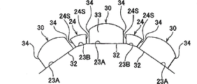
Fig. 3 A is the end view of rotor yoke;
Fig. 3 B is the front view of rotor yoke;
Fig. 4 is the side cross-sectional, view of projection;
Fig. 5 is the concept map of electrically powered steering apparatus using same;
Fig. 6 A is the end view according to the rotor yoke of modified example;
Fig. 6 B is the front view according to the rotor yoke of modified example;
Fig. 7 is the exploded perspective view according to the rotor of modified example;
Fig. 8 A is the end view according to the rotor yoke of modified example;
Fig. 8 B is the front view according to the rotor yoke of modified example;
Fig. 9 is the flux pattern of the motor of correlation technique.
Embodiment
[the first execution mode] hereinafter provides the explanation based on the first execution mode of the present invention of Fig. 1 to 4.The motor 10 that is shown among Fig. 1 is three-phase alternating current motors of not being with brush, and the stator 11 of this motor 10 adopts following structure: stator core 13 is fixed in the inside of motor shell 12 by being bonded with each other with motor shell 12.Motor shell 12 for example is the cylindrical in form of closed at both ends.In addition, stator core 13 has following structure: a plurality of tooth 13T are radially inwardly outstanding from the interior perimeter surface of cylinder body 13A, and induction loop 14 be wrapped in respectively each tooth 13T around.
The rotor 20 of this motor 10 has following structure: armature spindle 21 passes the center of rotor yoke 22, and a plurality of magnetic shoe 30 is fixed in the side of rotor yoke 22.As shown in Figure 2, magnetic shoe 30 roughly is the long slab shape of extending along the axial direction of rotor magnetic shoe 22, is provided with fixed pan 32 in the side that is positioned at rotor yoke 22 sides, and is being provided with first surface 31 with fixed pan 32 opposite sides.First surface 31 is the circular arc form that give prominence to gradually at the center from magnetic shoe 30 two ends in axial direction towards Width.In addition, magnetic shoe 30 in axial direction two sides 34 and the two ends 33 of broad ways meet at right angles with fixed pan 32.
In the present embodiment, the fixed pan 32 of magnetic shoe 30 is fixed in magnet standing part 23A by adhesive.Among each magnet standing part 23A, in the central part of rotor yoke 22 axial directions, be formed with adhesive recess 23C, adhesive recess 23C is by with respect to the recessed extremely shallow degree of depth in the two ends of rotor yoke 22, for example, about 0.5mm.When magnetic shoe 30 is fixed in magnet standing part 23A by adhesive, between adhesive recess 23C and fixed pan 32, form the adhesive phase with specific thickness, as shown in Figure 4.And, as shown in Figure 2, because the part that runs through at armature spindle 21 is formed with a plurality of hole 22A on every side in rotor yoke 22, therefore reduced the weight of rotor yoke 22.Those parts that are clipped between the adjacent adhesive recess 23C from polygonal each turning of rotor yoke 22 are given prominence to and are formed according to projection 24 of the present invention.
As shown in Fig. 3 A, projection 24 all is arranged on the equidistant position, the center with rotor yoke 22 axial directions on the two ends of rotor yoke 22 axial directions, and in the present embodiment, each projection 24 all is placed in from rotor yoke 22 axial direction two ends than the position close to more from the center of rotor yoke 22 axial directions.And, the projection 24 that arranges in pairs along the axial direction of rotor yoke 22 also can be arranged in from rotor yoke 22 axial direction centers than the position close to more from the two ends of rotor yoke 22 axial directions, for example, rotor yoke 22 in axial direction is divided into the position of three equal parts, perhaps can accurately be placed in the two ends of axial direction and the middle place between the center.
As shown in Figure 2, each projection 24 consists of by lamination prodger 24K, and these prodgers 24K is laminated on the group that the two ends of rotor yoke 22 and the steel disc 22K between the center form from the polylith steel disc 22K that consists of rotor yoke 22 a part is outstanding.And every laminated steel sheets 22K all is positioned such that by for example unshowned interlocking portions they can not be offset out suitable position each other.
The enlarged drawing of projection 24 has been shown among Fig. 3 B.As shown in Fig. 3 B, the two sides 24S of projection 24 is from the magnet standing part 23A adjacent one another are rise that roughly meets at right angles.Thus, when the two sides 34 of magnetic shoe 30 were parallel to the side 24S of projection 24, projection 24 had following structure: along with from magnet standing part 23A more and more away from, its width broadens gradually.In addition, between the two sides 24S of the two sides 344 of magnetic shoe 30 and projection 24, be provided with the gap of regulation.
And, among projection 24, its outer surface in the face of the radial outside of rotor 20 has the second curved surface with the centres of rotor 20, and the radius of a circle that comprises this outer surface is less than the distance between the center of the part---such as two ends of first surface 31 broad wayss---at the center of the most close rotor 20 on the first surface 31 of magnetic shoe 30 and rotor 20.
Herein, as shown in Figure 4, the distance L 1 between the end face 24T separated from one another of the projection 24 that arranges in pairs along the axial direction of rotor yoke 22 is less than the total length L2 of magnetic shoe 30.Each projection 24 is configured to both ends of the surface 24T and is positioned at from the center of rotor yoke 22 axial directions than the position close to the two ends 33 of magnetic shoe 30.
The outer side engagement of cylindrical cap 35 and rotor yoke 22 also covers magnetic shoe 30.As shown in fig. 1, cylindrical cap 35 has following structure: thin cylinder part 35C and magnetic shoe 30 contact in inside, and flange 35A, 35B are radially inwardly outstanding from the two ends of cylindrical portions may 35C.Flange 35A, 35B are locked to the two ends of rotor yoke 22.
As shown in fig. 1, rotor 20 is configured such that each magnetic shoe 30 inside of all facing stator core 13 along its length.The two ends of armature spindle 21 rotatably and are pivotly supported by the bearing 16 in the end walls that is combined in motor shell 12.
And, in the motor 10 of present embodiment, be combined with the rotational position sensor 38 for detection of the position of rotation of rotor 20.
The structure of the motor 10 of present embodiment as mentioned above.Next, the method for the production of above-mentioned rotor 20 is described.In the process of producing rotor 20, to not have the laminate that the steel disc 22K of prodger 24K consists of by polylith is combined with the laminate that the steel disc 22K that is had prodger 24K by polylith consists of, with production rotor yoke 22, then armature spindle 21 is passed rotor yoke 22.
Next, adhesive is applied to adhesive recess 23C among the magnet standing part 23A of rotor yoke 22.Then, the fixed pan 32 of each magnetic shoe 30 is adhered to each magnet standing part 23A of rotor yoke 22.More specifically, the position that the fixed pan 32 of magnetic shoe 30 is pressed against magnet standing part 23A is upper, the two ends of the two ends 33 that are in magnetic shoe 30 and rotor yoke 22 aligns.So when applying adhesive was on whole adhesive recess 23C, the part adhesive was extruded along the Width of magnetic shoe 30, and enter into the two sides 34 of magnetic shoe 30 and the gap between the projection 24.Thus, when the fixed pan 32 of magnetic shoe 30 was adhered to magnet standing part 23A, the two sides 34 of magnetic shoe 30 Widths were adhered to the folded projection 24 of magnetic shoe 30 broad wayss.In addition, because adhesive is filled in the gap, can prevent that magnetic shoe 30 from moving.
Next, the cylindrical cap 35 that is shown among Fig. 2 is engaged with rotor yoke 22.At this moment, one of them flange among paired flange 35A, the 35B of cylindrical cap 35, flange 35B for example, 35C separates moulding with cylindrical portions may, and after the outer side engagement with cylindrical portions may 35C and rotor yoke 22, flange 35B for example welded or brazing in cylindrical portions may 35C, thereby finish rotor 20.
Next, the rotor 20 of present embodiment and interaction and the effect of motor 10 are described.When the motor drive current that will be the three-phase alternating current form is applied to motor 10, the intensity and the direction that are arranged on the magnetic flux of a plurality of induction loop 14 in the stator 11 change, because the magnetic force between each induction loop 14 and the magnetic shoe 30 causes rotor 20 with respect to stator 11 rotations.At this moment, as the result who applies electric current, induction loop 14 heatings.Because this heat, the temperature of rotor 20 rises.So, because thermal coefficient of expansion different between rotor yoke 22 and the magnetic shoe 30 cause the adhesive between rotor yoke 22 and the magnetic shoe 30 to be subject to stress.At this moment, because adhesive plays the effect of padded coaming, with the thermal deformation of absorption magnetic shoe 30 and rotor yoke 22, thereby can alleviate the stress that acts on the magnetic shoe 30.
But, if the frequent chance number that uses motor 10 and reach a high temperature increases under top load, so as the result who is subject to stress, can in adhesive, form the crack, and can reduce the bonding strength of adhesive.But according to the structure of the rotor 20 of present embodiment, shown in Fig. 3 B, each magnetic shoe 30 equal broad ways is clamped by a plurality of projections 24 that are arranged on the rotor yoke 22.Thus, even because adhesive causes the bonding strength between magnetic shoe 30 and the rotor yoke 22 to reduce, the situation of also having avoided magnetic shoe 30 being drawn onto the adjacent magnetic shoe 30 that is positioned at cylindrical cap 35 occurs.In addition, prevent that by cylindrical cap 35 magnetic shoe 30 from outwards separating along the radial direction of rotor 20, and limited the movement of magnetic shoe 30 along the axial direction of rotor 20 by flange 35A, the 35B of cylindrical cap 35.
And, in the rotor 20 of present embodiment, because projection 24 only partly is arranged on two positions of rotor yoke 22 axial directions, form continuously between the two ends of rotor yoke 22 axial directions with projection and to compare, can suppress from magnetic shoe 30 to projection 24 magnetic leakage.Thus, when the output torque of the motor 10 that magnetic leakage is minimized cause reduces, torque ripple and start and stop torque are minimized, thereby can improve motor performance.And, minimized by the reduction of the output torque that makes motor 10, can do motor less and lighter.
And, in the rotor 20 of present embodiment, because the projection 24 that arranges in pairs along the axial direction of rotor yoke 22 is positioned to respectively core from rotor yoke 22 axial directions than the position close to the two ends 33 of magnetic shoe 30 axial directions, projection 24 only needs to be for the intensity of guaranteeing projection 24 and to prevent that the stress of magnetic shoe 30 from concentrating needed minimum length along the length of the axial direction of rotor yoke 22, considers the long needs of length that make projection 24 owing to the magnetic shoe skew of tolerance thereby eliminated.
In addition, in the situation on the two ends that projection 24 are placed in rotor yoke 22, if rotor 20 in axial direction even very slightly moves from its suitable position with respect to stator 11, because the part of projection 24 is projected into outside the stator 11, therefore, even this moves is in admissible assembling scope, departing from of motor performance also can be quite large.On the contrary, in the rotor 20 of present embodiment, because projection 24 is not projected into outside the stator 11, be offset in the situation of the degree that still is positioned at admissible assembling scope at rotor 20, departing from of motor performance can be remained on quite low degree.
[the second execution mode] hereinafter describes for the execution mode according to electrically powered steering apparatus using same of the present invention.As shown in Figure 5, the electrically powered steering apparatus using same 100 of present embodiment is provided with runner connecting axle 102, and it extends being arranged on the pair of turning wheels 101 on the vehicle 110 and covering between the axle housing 103 in the outside of runner connecting axle 102.The two ends of runner connecting axle 102 are connected in each runner 101 via pull bar 102T, and axle housing 103 is fixed in the chassis of vehicle 110.In addition, be formed with the tooth bar (not shown) in the pars intermedia office of runner connecting axle 102, and pass pinion (not shown) and the engagement of this tooth bar of the mid portion of axle housing 103 from sidepiece.
By this way, the electrically powered steering apparatus using same 100 of present embodiment is provided with in the first embodiment the motor 10 as drive source, and because motor 10 has the motor performance of improvement, therefore, electrically powered steering apparatus using same 100 to turn to sense be stable.
[other execution mode] the present invention is not limited to aforementioned embodiments, but the execution mode of realizing in those modes of following explanation is all within the scope of the invention involved.And except the execution mode of following explanation, the present invention can also realize by making amendment in many ways in the scope that does not deviate from its main points.
(1) although in the above-described first embodiment, magnetic shoe 30 is fixed in rotor yoke 22 by adhesive, also can adopt magnetic shoe 30 only to utilize projection 24 and cylindrical cap 35 and does not utilize adhesive to be fixed in the structure of rotor yoke 22.More specifically, adopt magnetic shoe 30 to be clamped in from the width direction by the structure between the folded neighboring projection 24 of magnet standing part 23A.
(2) in addition, magnetic shoe 30 can only utilize projection 24 and not utilize adhesive or cylindrical cap 35 to be fixed in rotor yoke 22.More specifically, except by tilt to make towards fixed pan 32 shape of cross section of the two sides 34 of magnetic shoe 30 roughly be trapezoidal form so that they more near fixed pan 32 to each other more for away from, also the side 24S of the neighboring projection 24 on the both sides of magnet standing part 23A is inclined to so that they more near magnet standing part 23A to each other more for away from, thereby produce the structure that the side 32 of these sides 24S and magnetic shoe 30 contacts with each other.In addition, by with the side 24S of projection 24 and side 34 friction locks of magnetic shoe 30, prevent magnetic shoe 30 moving axially along rotor 20.
(3) although consist of projection 24 by integrally formed prodger 24K and a plurality of prodger 24K of lamination on the steel disc 22K that consists of rotor yoke 22 in the first embodiment, but projection 24 can be made of the parts of separating with rotor yoke 22, and can adopt the structure that for example by screw projection 24 is anchored on the boundary member of adjacent magnet standing part 23A.
(4) in addition, although consist of rotor yoke 22 by laminated steel sheets 22K, it also can be made of a large amount of magnetic materials, such as by with magnetic metallic powder with utilize the molded compressing powder core rolled-up stock of mould to consist of after toner mixes.
(5) as shown in Figure 6A and 6B, in each magnet standing part 23A, be formed with between the two ends of rotor yoke 22 axial directions and extend and the shallow slot 23M recessed with respect to adhesive recess 23C, and in shallow slot 23M and adhesive recess 23C, can accommodate adhesive.Thus, between the two ends of magnetic shoe 30 and magnet standing part 23A, be formed with equally the adhesive phase with specific thickness, thereby magnetic shoe 30 and magnet standing part 23A can be adhered to reliably.
(6) rotor yoke 22 can also following mode be constructed.That is, as shown in Figure 7, polygonal each corner in rotor yoke 22 forms plane 23B.As shown in Figure 8A and 8B, each projection 24 is erect from this plane 23B, and its two sides 24S on both sides with respect to the magnet standing part 23A of the adjacent plane 23B protuberance that roughly meets at right angles.At this moment, make plane 23B be clipped in part between the adjacent adhesive recess 23C with respect to the structure that is not clipped in the recessed extremely shallow degree of depth with adhesive recess 23C same amount of part between the adjacent adhesive recess 23C although can adopt, this part can also be not recessed.In the situation that adopts the not recessed structure of this part, because it is outstanding with respect to adhesive recess 23C to form the part of plane 23B, therefore, four sides of all of adhesive recess 23C center on by difference in height, thereby adhesive can be retained in the adhesive recess 23C.
(7) although adopted in the above-described embodiment projection 24 to be positioned in the structure of the position between the adjacent adhesive recess 23C in the mid portion that is clipped in rotor yoke 22 axial directions, the position (at the place, two ends of rotor yoke 22 axial directions) that also can adopt projection 24 to be positioned in not to be clipped between the adhesive recess 23C.
(8) although the present invention is applied to so-called pillar electrically powered steering apparatus using same, wherein in the above-described 2nd embodiment, motor 10 and the centre position of gear couplings in steering spindle 106, but the present invention also can be applicable to so-called rack-and-pinion electrically powered steering apparatus using same, wherein motor integral body has hollow structure and wherein is fixed with ball nut, and this ball nut meshes with the ball-screw of the pars intermedia office that is formed on runner connecting axle 102, perhaps the present invention can be applicable to the gear type electrically powered steering apparatus using same, wherein utilizes rack and pinion mechanism that motor is attached to the runner connecting axle.And the present invention not only is applied to electrically powered steering apparatus using same, but also can be applicable to industrial robot.
(9) although the present invention is applied to rotor 20 as the motor 10 of the drive source of electrically powered steering apparatus using same 100 in the second execution mode, the present invention also can be applicable to the rotor of industrial motor.
(10) although projection 24 is arranged on from the two ends 33 of magnetic shoe 30 axial directions towards the position of the off-centring of rotor yoke 22 axial directions in the second execution mode, projection 24 also can be arranged to be in the same plane with the two ends of rotor yoke 22 axial directions.
Claims (8)
1. motor rotor comprises:
Rotor yoke (22);
Be formed on a plurality of magnet standing parts (23A) on the side of described rotor yoke (22),
Magnetic shoe (30), described magnetic shoe (30) is individually fixed in described magnet standing part (23A), and extends along the axial direction of described rotor yoke (22); With
Projection (24), described projection (24) are arranged on each boundary between each the adjacent magnet standing part (23A) that is positioned at described rotor yoke (22), and outwards outstanding from described rotor yoke (22), it is characterized in that,
Described projection (24) arranges in pairs along the axial direction of described rotor yoke (22), and
Rise from magnet standing part (23A) adjacent one another are the two sides (24S) of described projection (24), and, between the two sides (24S) of the two sides (344) of described magnetic shoe (30) and described projection (24), be provided with the gap of regulation.
2. motor rotor according to claim 1, wherein
The described projection (24) that arranges in pairs along the axial direction of described rotor yoke (22) is placed in the position between the center of every end of being positioned at described rotor yoke (22) and described rotor yoke (22) axial direction.
3. motor rotor according to claim 1 and 2 further comprises:
Adhesive recess (23C), described adhesive recess (23C) forms in each described magnet standing part (23A), and the mid portion of described adhesive recess (23C) by making described rotor yoke (22) axial direction is with respect to recessed formation the in two ends of described rotor yoke (22);
Wherein, described projection (24) is placed in the folded position of adhesive recess (23C) by adjacent magnet standing part (23A).
4. motor rotor according to claim 3 further comprises:
Be arranged on the groove (23M) in the described adhesive recess (23C).
5. motor rotor according to claim 1 and 2 further comprises
With the outer side engagement of described rotor yoke (22) and cover the cylindrical cap (35) of described a plurality of magnetic shoe (30).
6. motor rotor according to claim 5, wherein
Described cylindrical cap (35) comprises cylindrical portions may (35C) and flange (35A, 35B), and described flange (35A, 35B) extends radially inwardly from the end of described cylindrical portions may (35C) axial direction.
7. motor rotor according to claim 1 and 2, wherein
Described rotor yoke (22) is polygonal column.
8. motor rotor according to claim 1 and 2, wherein
Described rotor (20) uses the motor (10) at the electric assistant steering device that is used for auxiliary steering force from deflecting roller (107).
Applications Claiming Priority (3)
| Application Number | Priority Date | Filing Date | Title |
|---|---|---|---|
| JP2008115137 | 2008-04-25 | ||
| JP2008-115137 | 2008-04-25 | ||
| JP2008115137A JP5501572B2 (en) | 2008-04-25 | 2008-04-25 | Motor rotor and electric power steering device |
Publications (2)
| Publication Number | Publication Date |
|---|---|
| CN101567594A CN101567594A (en) | 2009-10-28 |
| CN101567594B true CN101567594B (en) | 2013-10-16 |
Family
ID=41214278
Family Applications (1)
| Application Number | Title | Priority Date | Filing Date |
|---|---|---|---|
| CN200910137359.2A Expired - Fee Related CN101567594B (en) | 2008-04-25 | 2009-04-24 | Motor rotor and electric power steering apparatus |
Country Status (3)
| Country | Link |
|---|---|
| US (1) | US8040006B2 (en) |
| JP (1) | JP5501572B2 (en) |
| CN (1) | CN101567594B (en) |
Families Citing this family (26)
| Publication number | Priority date | Publication date | Assignee | Title |
|---|---|---|---|---|
| EP1368813B1 (en) | 2000-12-15 | 2014-12-03 | The Arizona Board of Regents on behalf of the University of Arizona | Method for patterning metal using nanoparticle containing precursors |
| CA2785084A1 (en) * | 2009-12-21 | 2011-06-30 | Hoeganaes Ab (Publ) | Rotor for modulated pole machine |
| CN103053094B (en) * | 2010-09-06 | 2015-10-14 | 三菱电机株式会社 | Permanent-magnet type electric rotating machine and utilize the driven steering device of this permanent-magnet type electric rotating machine |
| SI23980A (en) * | 2012-01-10 | 2013-07-31 | Nela Razvojni Center D.O.O. Podružnica Otoki | The rotor with permanent magnets of synchronous electro motor |
| JP5326014B2 (en) * | 2012-02-16 | 2013-10-30 | ファナック株式会社 | Rotor for electric motor having structure for securely attaching magnet to outer peripheral surface of iron core and method for manufacturing the same |
| KR101342290B1 (en) * | 2012-06-28 | 2013-12-16 | 엘지이노텍 주식회사 | Motor |
| US9935506B2 (en) | 2012-08-31 | 2018-04-03 | Lappeenranta University Of Technology | Electrical machine |
| JP2014068460A (en) * | 2012-09-26 | 2014-04-17 | Seiko Epson Corp | Electromechanical device, rotor used in electromechanical device, and movable body and robot using electromechanical device |
| JP5602815B2 (en) * | 2012-10-30 | 2014-10-08 | ファナック株式会社 | Rotor having a protrusion for positioning a permanent magnet and electric motor comprising such a rotor |
| WO2014125568A1 (en) * | 2013-02-12 | 2014-08-21 | 三菱電機株式会社 | Motor drive device |
| JP2014155372A (en) * | 2013-02-12 | 2014-08-25 | Mitsubishi Electric Corp | Surface magnet rotor and manufacturing method therefor and permanent magnet dynamo-electric machine with surface magnet rotor and electric power steering device using permanent magnet dynamo-electric machine |
| CN104113153A (en) * | 2013-07-05 | 2014-10-22 | 美的威灵电机技术(上海)有限公司 | Motor and manufacturing method thereof |
| JP2015122842A (en) * | 2013-12-20 | 2015-07-02 | ファナック株式会社 | Rotor for motor with magnet, motor, and manufacturing method of rotor |
| JP5808445B2 (en) * | 2014-02-21 | 2015-11-10 | ファナック株式会社 | Rotor for electric motor including magnet attached to outer peripheral surface of rotor core, electric motor, and method for manufacturing electric motor rotor |
| EP3139478B1 (en) * | 2014-04-29 | 2022-04-27 | Mitsubishi Electric Corporation | Permanent magnet motor |
| JP2016093068A (en) * | 2014-11-11 | 2016-05-23 | 日本電産サンキョー株式会社 | Rotary electric machine |
| EP3076520B1 (en) * | 2015-03-31 | 2017-11-01 | Siemens Aktiengesellschaft | Rotor for an electric machine and production method |
| JP6828307B2 (en) * | 2016-08-24 | 2021-02-10 | 株式会社デンソー | How to manufacture rotors and motors |
| JPWO2018105046A1 (en) * | 2016-12-07 | 2018-12-06 | 三菱電機株式会社 | Permanent magnet rotating electric machine |
| KR102583066B1 (en) * | 2018-04-10 | 2023-09-27 | 엘지이노텍 주식회사 | Motor |
| WO2020035925A1 (en) * | 2018-08-16 | 2020-02-20 | 三菱電機株式会社 | Rotating electric machine |
| JP2020043695A (en) * | 2018-09-11 | 2020-03-19 | 株式会社日立製作所 | Rotary electric machine, and hoist system for elevator |
| JP7238312B2 (en) * | 2018-09-28 | 2023-03-14 | 日本電産株式会社 | motor |
| WO2020067245A1 (en) * | 2018-09-28 | 2020-04-02 | 日本電産株式会社 | Rotor, method for manufacturing rotor, and motor |
| KR20200067495A (en) * | 2018-12-04 | 2020-06-12 | 엘지이노텍 주식회사 | Motor |
| WO2023148953A1 (en) * | 2022-02-07 | 2023-08-10 | 三菱電機株式会社 | Rotor, electric motor, air blower, air conditioning device, and method for producing electric motor |
Citations (4)
| Publication number | Priority date | Publication date | Assignee | Title |
|---|---|---|---|---|
| US5063318A (en) * | 1989-08-25 | 1991-11-05 | Sundstrand Corporation | Preloaded permanent magnet rotor assembly |
| US5140210A (en) * | 1988-07-07 | 1992-08-18 | Mitsubishi Denki K.K. | Permanent-magnet type dynamoelectric machine rotor |
| US5760520A (en) * | 1995-12-27 | 1998-06-02 | Aisin Aw Co., Ltd. | Motor |
| CN1521919A (en) * | 2003-01-16 | 2004-08-18 | 株式会社萌力克 | Rotary electrical apparatus |
Family Cites Families (14)
| Publication number | Priority date | Publication date | Assignee | Title |
|---|---|---|---|---|
| US4742259A (en) * | 1987-05-11 | 1988-05-03 | Franklin Electric Co., Inc. | Permanent magnet rotor for electric motor |
| GB2217924B (en) * | 1988-04-25 | 1992-10-07 | Matsushita Electric Works Ltd | Permanent magnet rotor |
| JP3398977B2 (en) * | 1992-07-14 | 2003-04-21 | 株式会社安川電機 | Permanent magnet field rotor |
| JP3638695B2 (en) * | 1996-01-25 | 2005-04-13 | 山洋電気株式会社 | Permanent magnet rotor |
| JP3779097B2 (en) * | 1999-07-23 | 2006-05-24 | 日本電産サンキョー株式会社 | Electric motor rotor |
| JP4598243B2 (en) * | 2000-06-23 | 2010-12-15 | アスモ株式会社 | Rotating magnetic field type electric motor |
| JP2004222455A (en) * | 2003-01-16 | 2004-08-05 | Moric Co Ltd | Rotating electric equipment |
| JP2005065388A (en) * | 2003-08-08 | 2005-03-10 | Favess Co Ltd | Permanent magnet rotating electric machine |
| JP2006271057A (en) | 2005-03-23 | 2006-10-05 | Toshiba Mitsubishi-Electric Industrial System Corp | Rotor of permanent magnet synchronous motor |
| JP2007037289A (en) * | 2005-07-27 | 2007-02-08 | Meidensha Corp | Permanent magnet rotary electric machine |
| DE502005010177D1 (en) * | 2005-07-29 | 2010-10-14 | Siemens Ag | Permanent magnet rotor for a brushless electric machine |
| JP5352949B2 (en) * | 2006-09-04 | 2013-11-27 | 株式会社ジェイテクト | Magnet type motor |
| JP4671997B2 (en) * | 2007-10-23 | 2011-04-20 | 三菱電機株式会社 | Rotor for rotating electrical machine and method for manufacturing the same |
| JP5454753B2 (en) * | 2008-04-21 | 2014-03-26 | 株式会社ジェイテクト | Motor rotor and electric power steering device |
-
2008
- 2008-04-25 JP JP2008115137A patent/JP5501572B2/en not_active Expired - Fee Related
-
2009
- 2009-04-23 US US12/428,562 patent/US8040006B2/en not_active Expired - Fee Related
- 2009-04-24 CN CN200910137359.2A patent/CN101567594B/en not_active Expired - Fee Related
Patent Citations (4)
| Publication number | Priority date | Publication date | Assignee | Title |
|---|---|---|---|---|
| US5140210A (en) * | 1988-07-07 | 1992-08-18 | Mitsubishi Denki K.K. | Permanent-magnet type dynamoelectric machine rotor |
| US5063318A (en) * | 1989-08-25 | 1991-11-05 | Sundstrand Corporation | Preloaded permanent magnet rotor assembly |
| US5760520A (en) * | 1995-12-27 | 1998-06-02 | Aisin Aw Co., Ltd. | Motor |
| CN1521919A (en) * | 2003-01-16 | 2004-08-18 | 株式会社萌力克 | Rotary electrical apparatus |
Non-Patent Citations (3)
| Title |
|---|
| JP特开2001-37122A 2001.02.09 |
| JP特开2005-65388A 2005.03.10 |
| JP特开2006-271057A 2006.10.05 |
Also Published As
| Publication number | Publication date |
|---|---|
| US20090267438A1 (en) | 2009-10-29 |
| CN101567594A (en) | 2009-10-28 |
| US8040006B2 (en) | 2011-10-18 |
| JP5501572B2 (en) | 2014-05-21 |
| JP2009268263A (en) | 2009-11-12 |
Similar Documents
| Publication | Publication Date | Title |
|---|---|---|
| CN101567594B (en) | Motor rotor and electric power steering apparatus | |
| US8203245B2 (en) | Motor rotor, having magnet holding projections | |
| US6597078B2 (en) | Electric power steering system including a permanent magnet motor | |
| JP4821303B2 (en) | Brushless motor and electric power steering apparatus using the same | |
| US20020047460A1 (en) | Electric power steering apparatus | |
| JP5359859B2 (en) | Brushless motor rotor, brushless motor, electric power steering apparatus, and method for manufacturing brushless motor rotor | |
| JPWO2008050637A1 (en) | Brushless motor | |
| US20130154436A1 (en) | Permanent magnet type rotary electric machine and electric power steering apparatus using the same | |
| US20140084728A1 (en) | Rotating electrical machine and electric power steering system using the same | |
| JP5966400B2 (en) | Brushless motor and electric power steering device | |
| WO2017163523A1 (en) | Rotary electric machine, electric power steering device, and manufacturing method for rotary electric machine | |
| JP2008022674A (en) | Electric motor | |
| CN110546857B (en) | Motor and electric power steering apparatus | |
| WO2015151344A1 (en) | Permanent magnet brushless motor | |
| JP5814206B2 (en) | Stator core | |
| JP5470913B2 (en) | Motor core, motor core unit using the same, brushless motor, electric power steering device using the same, and method for manufacturing motor core unit | |
| JP2005065388A (en) | Permanent magnet rotating electric machine | |
| JP2006121821A (en) | Synchronous reluctance motor and electric steering device mounted with the synchronous reluctance motor | |
| JP2008114787A (en) | Electric power steering device | |
| JP5327094B2 (en) | Brushless motor stator, brushless motor, and electric power steering apparatus | |
| EP2112743B1 (en) | Motor rotor and electric power steering apparatus | |
| JP7219100B2 (en) | Rotating electric machine and electric auxiliary machine device for automobile equipped with this rotating electric machine | |
| JP5966399B2 (en) | Brushless motor and electric power steering device | |
| CN110495073B (en) | Stator, motor, and electric power steering device | |
| WO2020036042A1 (en) | Stator, rotating electric machine, and automobile electric auxiliary device |
Legal Events
| Date | Code | Title | Description |
|---|---|---|---|
| C06 | Publication | ||
| PB01 | Publication | ||
| C10 | Entry into substantive examination | ||
| SE01 | Entry into force of request for substantive examination | ||
| C14 | Grant of patent or utility model | ||
| GR01 | Patent grant | ||
| CF01 | Termination of patent right due to non-payment of annual fee | ||
| CF01 | Termination of patent right due to non-payment of annual fee |
Granted publication date: 20131016 |