CN101460102A - Implantable device - Google Patents
Implantable device Download PDFInfo
- Publication number
- CN101460102A CN101460102A CNA200780020740XA CN200780020740A CN101460102A CN 101460102 A CN101460102 A CN 101460102A CN A200780020740X A CNA200780020740X A CN A200780020740XA CN 200780020740 A CN200780020740 A CN 200780020740A CN 101460102 A CN101460102 A CN 101460102A
- Authority
- CN
- China
- Prior art keywords
- implantable device
- shape
- sub
- silk
- carrier structure
- Prior art date
- Legal status (The legal status is an assumption and is not a legal conclusion. Google has not performed a legal analysis and makes no representation as to the accuracy of the status listed.)
- Granted
Links
- 241001465754 Metazoa Species 0.000 claims abstract description 24
- 239000004744 fabric Substances 0.000 claims abstract description 20
- 210000000056 organ Anatomy 0.000 claims abstract description 16
- 239000007943 implant Substances 0.000 claims description 81
- 239000000463 material Substances 0.000 claims description 62
- 238000005452 bending Methods 0.000 claims description 36
- 238000000034 method Methods 0.000 claims description 34
- 238000007599 discharging Methods 0.000 claims description 23
- 239000010410 layer Substances 0.000 claims description 21
- 239000003814 drug Substances 0.000 claims description 18
- 239000011229 interlayer Substances 0.000 claims description 16
- 208000003278 patent ductus arteriosus Diseases 0.000 claims description 16
- 230000015572 biosynthetic process Effects 0.000 claims description 15
- 230000000694 effects Effects 0.000 claims description 14
- 238000001356 surgical procedure Methods 0.000 claims description 14
- 238000009954 braiding Methods 0.000 claims description 13
- 230000000295 complement effect Effects 0.000 claims description 13
- 238000002372 labelling Methods 0.000 claims description 13
- 230000008569 process Effects 0.000 claims description 13
- 229910001000 nickel titanium Inorganic materials 0.000 claims description 12
- HLXZNVUGXRDIFK-UHFFFAOYSA-N nickel titanium Chemical compound [Ti].[Ti].[Ti].[Ti].[Ti].[Ti].[Ti].[Ti].[Ti].[Ti].[Ti].[Ni].[Ni].[Ni].[Ni].[Ni].[Ni].[Ni].[Ni].[Ni].[Ni].[Ni].[Ni].[Ni].[Ni] HLXZNVUGXRDIFK-UHFFFAOYSA-N 0.000 claims description 11
- 229920000642 polymer Polymers 0.000 claims description 11
- 239000000835 fiber Substances 0.000 claims description 10
- 229920000728 polyester Polymers 0.000 claims description 10
- 229940079593 drug Drugs 0.000 claims description 9
- 238000002513 implantation Methods 0.000 claims description 9
- 239000002356 single layer Substances 0.000 claims description 9
- 238000005516 engineering process Methods 0.000 claims description 8
- 238000012423 maintenance Methods 0.000 claims description 8
- BASFCYQUMIYNBI-UHFFFAOYSA-N platinum Chemical compound [Pt] BASFCYQUMIYNBI-UHFFFAOYSA-N 0.000 claims description 8
- -1 polyethylene Polymers 0.000 claims description 8
- 239000004814 polyurethane Substances 0.000 claims description 8
- 239000004698 Polyethylene Substances 0.000 claims description 7
- 238000005240 physical vapour deposition Methods 0.000 claims description 7
- 229920001490 poly(butyl methacrylate) polymer Polymers 0.000 claims description 7
- 238000012797 qualification Methods 0.000 claims description 7
- 229930012538 Paclitaxel Natural products 0.000 claims description 6
- 229960000446 abciximab Drugs 0.000 claims description 6
- 238000007667 floating Methods 0.000 claims description 6
- 125000000524 functional group Chemical group 0.000 claims description 6
- PCHJSUWPFVWCPO-UHFFFAOYSA-N gold Chemical compound [Au] PCHJSUWPFVWCPO-UHFFFAOYSA-N 0.000 claims description 6
- 239000010931 gold Substances 0.000 claims description 6
- 229910052737 gold Inorganic materials 0.000 claims description 6
- 229960001592 paclitaxel Drugs 0.000 claims description 6
- 229920003023 plastic Polymers 0.000 claims description 6
- 239000004033 plastic Substances 0.000 claims description 6
- 229920002635 polyurethane Polymers 0.000 claims description 6
- 239000012781 shape memory material Substances 0.000 claims description 6
- RCINICONZNJXQF-MZXODVADSA-N taxol Chemical compound O([C@@H]1[C@@]2(C[C@@H](C(C)=C(C2(C)C)[C@H](C([C@]2(C)[C@@H](O)C[C@H]3OC[C@]3([C@H]21)OC(C)=O)=O)OC(=O)C)OC(=O)[C@H](O)[C@@H](NC(=O)C=1C=CC=CC=1)C=1C=CC=CC=1)O)C(=O)C1=CC=CC=C1 RCINICONZNJXQF-MZXODVADSA-N 0.000 claims description 6
- 229910052799 carbon Inorganic materials 0.000 claims description 5
- 238000003618 dip coating Methods 0.000 claims description 5
- 239000002114 nanocomposite Substances 0.000 claims description 5
- 229920000573 polyethylene Polymers 0.000 claims description 5
- 238000004528 spin coating Methods 0.000 claims description 5
- 230000000007 visual effect Effects 0.000 claims description 5
- OHCQJHSOBUTRHG-KGGHGJDLSA-N FORSKOLIN Chemical compound O=C([C@@]12O)C[C@](C)(C=C)O[C@]1(C)[C@@H](OC(=O)C)[C@@H](O)[C@@H]1[C@]2(C)[C@@H](O)CCC1(C)C OHCQJHSOBUTRHG-KGGHGJDLSA-N 0.000 claims description 4
- 102000007625 Hirudins Human genes 0.000 claims description 4
- 108010007267 Hirudins Proteins 0.000 claims description 4
- 229960001123 epoprostenol Drugs 0.000 claims description 4
- KAQKFAOMNZTLHT-VVUHWYTRSA-N epoprostenol Chemical compound O1C(=CCCCC(O)=O)C[C@@H]2[C@@H](/C=C/[C@@H](O)CCCCC)[C@H](O)C[C@@H]21 KAQKFAOMNZTLHT-VVUHWYTRSA-N 0.000 claims description 4
- WQPDUTSPKFMPDP-OUMQNGNKSA-N hirudin Chemical compound C([C@@H](C(=O)N[C@@H](CCC(O)=O)C(=O)N[C@@H](CCC(O)=O)C(=O)N[C@@H]([C@@H](C)CC)C(=O)N1[C@@H](CCC1)C(=O)N[C@@H](CCC(O)=O)C(=O)N[C@@H](CCC(O)=O)C(=O)N[C@@H](CC=1C=CC(OS(O)(=O)=O)=CC=1)C(=O)N[C@@H](CC(C)C)C(=O)N[C@@H](CCC(N)=O)C(O)=O)NC(=O)[C@H](CC(O)=O)NC(=O)CNC(=O)[C@H](CC(O)=O)NC(=O)[C@H](CC(N)=O)NC(=O)[C@H](CC=1NC=NC=1)NC(=O)[C@H](CO)NC(=O)[C@H](CCC(N)=O)NC(=O)[C@H]1N(CCC1)C(=O)[C@H](CCCCN)NC(=O)[C@H]1N(CCC1)C(=O)[C@@H](NC(=O)CNC(=O)[C@H](CCC(O)=O)NC(=O)CNC(=O)[C@@H](NC(=O)[C@@H](NC(=O)[C@H]1NC(=O)[C@H](CCC(N)=O)NC(=O)[C@H](CC(N)=O)NC(=O)[C@H](CCCCN)NC(=O)[C@H](CCC(O)=O)NC(=O)CNC(=O)[C@H](CC(O)=O)NC(=O)[C@H](CO)NC(=O)CNC(=O)[C@H](CC(C)C)NC(=O)[C@H]([C@@H](C)CC)NC(=O)[C@@H]2CSSC[C@@H](C(=O)N[C@@H](CCC(O)=O)C(=O)NCC(=O)N[C@@H](CO)C(=O)N[C@@H](CC(N)=O)C(=O)N[C@H](C(=O)N[C@H](C(NCC(=O)N[C@@H](CCC(N)=O)C(=O)NCC(=O)N[C@@H](CC(N)=O)C(=O)N[C@@H](CCCCN)C(=O)N2)=O)CSSC1)C(C)C)NC(=O)[C@H](CC(C)C)NC(=O)[C@H]1NC(=O)[C@H](CC(C)C)NC(=O)[C@H](CC(N)=O)NC(=O)[C@H](CCC(N)=O)NC(=O)CNC(=O)[C@H](CO)NC(=O)[C@H](CCC(O)=O)NC(=O)[C@H]([C@@H](C)O)NC(=O)[C@@H](NC(=O)[C@H](CC(O)=O)NC(=O)[C@@H](NC(=O)[C@H](CC=2C=CC(O)=CC=2)NC(=O)[C@@H](NC(=O)[C@@H](N)C(C)C)C(C)C)[C@@H](C)O)CSSC1)C(C)C)[C@@H](C)O)[C@@H](C)O)C1=CC=CC=C1 WQPDUTSPKFMPDP-OUMQNGNKSA-N 0.000 claims description 4
- 229940006607 hirudin Drugs 0.000 claims description 4
- 229910052588 hydroxylapatite Inorganic materials 0.000 claims description 4
- 229910052741 iridium Inorganic materials 0.000 claims description 4
- GKOZUEZYRPOHIO-UHFFFAOYSA-N iridium atom Chemical compound [Ir] GKOZUEZYRPOHIO-UHFFFAOYSA-N 0.000 claims description 4
- 229910052751 metal Inorganic materials 0.000 claims description 4
- 239000002184 metal Substances 0.000 claims description 4
- SIWVEOZUMHYXCS-UHFFFAOYSA-N oxo(oxoyttriooxy)yttrium Chemical compound O=[Y]O[Y]=O SIWVEOZUMHYXCS-UHFFFAOYSA-N 0.000 claims description 4
- XYJRXVWERLGGKC-UHFFFAOYSA-D pentacalcium;hydroxide;triphosphate Chemical compound [OH-].[Ca+2].[Ca+2].[Ca+2].[Ca+2].[Ca+2].[O-]P([O-])([O-])=O.[O-]P([O-])([O-])=O.[O-]P([O-])([O-])=O XYJRXVWERLGGKC-UHFFFAOYSA-D 0.000 claims description 4
- YHHSONZFOIEMCP-UHFFFAOYSA-O phosphocholine Chemical compound C[N+](C)(C)CCOP(O)(O)=O YHHSONZFOIEMCP-UHFFFAOYSA-O 0.000 claims description 4
- 229910052697 platinum Inorganic materials 0.000 claims description 4
- 229950000845 politef Drugs 0.000 claims description 4
- 229920001432 poly(L-lactide) Polymers 0.000 claims description 4
- 238000007789 sealing Methods 0.000 claims description 4
- KIUKXJAPPMFGSW-DNGZLQJQSA-N (2S,3S,4S,5R,6R)-6-[(2S,3R,4R,5S,6R)-3-Acetamido-2-[(2S,3S,4R,5R,6R)-6-[(2R,3R,4R,5S,6R)-3-acetamido-2,5-dihydroxy-6-(hydroxymethyl)oxan-4-yl]oxy-2-carboxy-4,5-dihydroxyoxan-3-yl]oxy-5-hydroxy-6-(hydroxymethyl)oxan-4-yl]oxy-3,4,5-trihydroxyoxane-2-carboxylic acid Chemical compound CC(=O)N[C@H]1[C@H](O)O[C@H](CO)[C@@H](O)[C@@H]1O[C@H]1[C@H](O)[C@@H](O)[C@H](O[C@H]2[C@@H]([C@@H](O[C@H]3[C@@H]([C@@H](O)[C@H](O)[C@H](O3)C(O)=O)O)[C@H](O)[C@@H](CO)O2)NC(C)=O)[C@@H](C(O)=O)O1 KIUKXJAPPMFGSW-DNGZLQJQSA-N 0.000 claims description 3
- YHHSONZFOIEMCP-UHFFFAOYSA-N 2-(trimethylazaniumyl)ethyl hydrogen phosphate Chemical compound C[N+](C)(C)CCOP(O)([O-])=O YHHSONZFOIEMCP-UHFFFAOYSA-N 0.000 claims description 3
- SQDAZGGFXASXDW-UHFFFAOYSA-N 5-bromo-2-(trifluoromethoxy)pyridine Chemical compound FC(F)(F)OC1=CC=C(Br)C=N1 SQDAZGGFXASXDW-UHFFFAOYSA-N 0.000 claims description 3
- 229920001287 Chondroitin sulfate Polymers 0.000 claims description 3
- 102000008186 Collagen Human genes 0.000 claims description 3
- 108010035532 Collagen Proteins 0.000 claims description 3
- 102000016942 Elastin Human genes 0.000 claims description 3
- 108010014258 Elastin Proteins 0.000 claims description 3
- 102000009123 Fibrin Human genes 0.000 claims description 3
- 108010073385 Fibrin Proteins 0.000 claims description 3
- BWGVNKXGVNDBDI-UHFFFAOYSA-N Fibrin monomer Chemical compound CNC(=O)CNC(=O)CN BWGVNKXGVNDBDI-UHFFFAOYSA-N 0.000 claims description 3
- HTTJABKRGRZYRN-UHFFFAOYSA-N Heparin Chemical compound OC1C(NC(=O)C)C(O)OC(COS(O)(=O)=O)C1OC1C(OS(O)(=O)=O)C(O)C(OC2C(C(OS(O)(=O)=O)C(OC3C(C(O)C(O)C(O3)C(O)=O)OS(O)(=O)=O)C(CO)O2)NS(O)(=O)=O)C(C(O)=O)O1 HTTJABKRGRZYRN-UHFFFAOYSA-N 0.000 claims description 3
- CTQNGGLPUBDAKN-UHFFFAOYSA-N O-Xylene Chemical compound CC1=CC=CC=C1C CTQNGGLPUBDAKN-UHFFFAOYSA-N 0.000 claims description 3
- RTAQQCXQSZGOHL-UHFFFAOYSA-N Titanium Chemical compound [Ti] RTAQQCXQSZGOHL-UHFFFAOYSA-N 0.000 claims description 3
- 241000700605 Viruses Species 0.000 claims description 3
- 239000002253 acid Substances 0.000 claims description 3
- 229920002678 cellulose Polymers 0.000 claims description 3
- 239000001913 cellulose Substances 0.000 claims description 3
- 229910010293 ceramic material Inorganic materials 0.000 claims description 3
- 229940059329 chondroitin sulfate Drugs 0.000 claims description 3
- 229920001436 collagen Polymers 0.000 claims description 3
- 229920002549 elastin Polymers 0.000 claims description 3
- 150000002148 esters Chemical class 0.000 claims description 3
- 238000005530 etching Methods 0.000 claims description 3
- 229950003499 fibrin Drugs 0.000 claims description 3
- 229920000669 heparin Polymers 0.000 claims description 3
- 229960002897 heparin Drugs 0.000 claims description 3
- 229920002674 hyaluronan Polymers 0.000 claims description 3
- 229960003160 hyaluronic acid Drugs 0.000 claims description 3
- 238000005468 ion implantation Methods 0.000 claims description 3
- 238000010884 ion-beam technique Methods 0.000 claims description 3
- 229950004354 phosphorylcholine Drugs 0.000 claims description 3
- 229920001596 poly (chlorostyrenes) Polymers 0.000 claims description 3
- 239000004626 polylactic acid Substances 0.000 claims description 3
- 229920001343 polytetrafluoroethylene Polymers 0.000 claims description 3
- 239000004810 polytetrafluoroethylene Substances 0.000 claims description 3
- 238000004544 sputter deposition Methods 0.000 claims description 3
- 210000000130 stem cell Anatomy 0.000 claims description 3
- 239000010936 titanium Substances 0.000 claims description 3
- 229910052719 titanium Inorganic materials 0.000 claims description 3
- 230000002792 vascular Effects 0.000 claims description 3
- XLYOFNOQVPJJNP-UHFFFAOYSA-N water Substances O XLYOFNOQVPJJNP-UHFFFAOYSA-N 0.000 claims description 3
- 108010074415 Angiogenic Proteins Proteins 0.000 claims description 2
- 102000008076 Angiogenic Proteins Human genes 0.000 claims description 2
- 229920004934 Dacron® Polymers 0.000 claims description 2
- SUZLHDUTVMZSEV-UHFFFAOYSA-N Deoxycoleonol Natural products C12C(=O)CC(C)(C=C)OC2(C)C(OC(=O)C)C(O)C2C1(C)C(O)CCC2(C)C SUZLHDUTVMZSEV-UHFFFAOYSA-N 0.000 claims description 2
- JZRZLCJJYWKEPX-UHFFFAOYSA-N FC(CO[P])(F)F Chemical compound FC(CO[P])(F)F JZRZLCJJYWKEPX-UHFFFAOYSA-N 0.000 claims description 2
- OHCQJHSOBUTRHG-UHFFFAOYSA-N colforsin Natural products OC12C(=O)CC(C)(C=C)OC1(C)C(OC(=O)C)C(O)C1C2(C)C(O)CCC1(C)C OHCQJHSOBUTRHG-UHFFFAOYSA-N 0.000 claims description 2
- 238000013461 design Methods 0.000 claims description 2
- 239000000284 extract Substances 0.000 claims description 2
- 229910010272 inorganic material Inorganic materials 0.000 claims description 2
- 239000011147 inorganic material Substances 0.000 claims description 2
- 239000003550 marker Substances 0.000 claims description 2
- 229910001092 metal group alloy Inorganic materials 0.000 claims description 2
- 238000012544 monitoring process Methods 0.000 claims description 2
- 229920000747 poly(lactic acid) Polymers 0.000 claims description 2
- 239000005020 polyethylene terephthalate Substances 0.000 claims description 2
- 229910010271 silicon carbide Inorganic materials 0.000 claims description 2
- 239000000126 substance Substances 0.000 claims description 2
- 229920001059 synthetic polymer Polymers 0.000 claims description 2
- QTBSBXVTEAMEQO-UHFFFAOYSA-N Acetic acid Chemical compound CC(O)=O QTBSBXVTEAMEQO-UHFFFAOYSA-N 0.000 claims 6
- 230000003292 diminished effect Effects 0.000 claims 1
- 230000002950 deficient Effects 0.000 abstract description 2
- 239000010408 film Substances 0.000 description 101
- 210000000709 aorta Anatomy 0.000 description 24
- 210000002414 leg Anatomy 0.000 description 18
- 210000004204 blood vessel Anatomy 0.000 description 16
- 238000005755 formation reaction Methods 0.000 description 14
- 230000002349 favourable effect Effects 0.000 description 8
- 230000023555 blood coagulation Effects 0.000 description 7
- 239000011248 coating agent Substances 0.000 description 6
- 238000000576 coating method Methods 0.000 description 6
- 208000005189 Embolism Diseases 0.000 description 5
- 208000001910 Ventricular Heart Septal Defects Diseases 0.000 description 5
- 230000009471 action Effects 0.000 description 5
- 230000008859 change Effects 0.000 description 5
- 201000003130 ventricular septal defect Diseases 0.000 description 5
- 208000001435 Thromboembolism Diseases 0.000 description 4
- 239000000956 alloy Substances 0.000 description 4
- 210000004027 cell Anatomy 0.000 description 4
- 238000005229 chemical vapour deposition Methods 0.000 description 4
- 230000002093 peripheral effect Effects 0.000 description 4
- 239000000758 substrate Substances 0.000 description 4
- 238000004381 surface treatment Methods 0.000 description 4
- 241000272041 Naja Species 0.000 description 3
- 206010028980 Neoplasm Diseases 0.000 description 3
- 208000008883 Patent Foramen Ovale Diseases 0.000 description 3
- 229910045601 alloy Inorganic materials 0.000 description 3
- 230000017531 blood circulation Effects 0.000 description 3
- 238000010586 diagram Methods 0.000 description 3
- 239000005038 ethylene vinyl acetate Substances 0.000 description 3
- 208000025339 heart septal defect Diseases 0.000 description 3
- 210000005246 left atrium Anatomy 0.000 description 3
- 210000005240 left ventricle Anatomy 0.000 description 3
- 238000004519 manufacturing process Methods 0.000 description 3
- 229920001200 poly(ethylene-vinyl acetate) Polymers 0.000 description 3
- SOGAXMICEFXMKE-UHFFFAOYSA-N Butylmethacrylate Chemical compound CCCCOC(=O)C(C)=C SOGAXMICEFXMKE-UHFFFAOYSA-N 0.000 description 2
- 206010019233 Headaches Diseases 0.000 description 2
- 208000007474 aortic aneurysm Diseases 0.000 description 2
- 230000004323 axial length Effects 0.000 description 2
- 230000009286 beneficial effect Effects 0.000 description 2
- 230000008901 benefit Effects 0.000 description 2
- 230000000903 blocking effect Effects 0.000 description 2
- 239000008280 blood Substances 0.000 description 2
- 210000004369 blood Anatomy 0.000 description 2
- 238000000151 deposition Methods 0.000 description 2
- 230000008021 deposition Effects 0.000 description 2
- 238000006073 displacement reaction Methods 0.000 description 2
- 210000003414 extremity Anatomy 0.000 description 2
- ZZUFCTLCJUWOSV-UHFFFAOYSA-N furosemide Chemical compound C1=C(Cl)C(S(=O)(=O)N)=CC(C(O)=O)=C1NCC1=CC=CO1 ZZUFCTLCJUWOSV-UHFFFAOYSA-N 0.000 description 2
- 231100000869 headache Toxicity 0.000 description 2
- 230000006872 improvement Effects 0.000 description 2
- 210000004971 interatrial septum Anatomy 0.000 description 2
- 239000003446 ligand Substances 0.000 description 2
- 238000002161 passivation Methods 0.000 description 2
- 238000012545 processing Methods 0.000 description 2
- 230000002685 pulmonary effect Effects 0.000 description 2
- ZAHRKKWIAAJSAO-UHFFFAOYSA-N rapamycin Natural products COCC(O)C(=C/C(C)C(=O)CC(OC(=O)C1CCCCN1C(=O)C(=O)C2(O)OC(CC(OC)C(=CC=CC=CC(C)CC(C)C(=O)C)C)CCC2C)C(C)CC3CCC(O)C(C3)OC)C ZAHRKKWIAAJSAO-UHFFFAOYSA-N 0.000 description 2
- 229920005989 resin Polymers 0.000 description 2
- 239000011347 resin Substances 0.000 description 2
- 210000005241 right ventricle Anatomy 0.000 description 2
- 229960002930 sirolimus Drugs 0.000 description 2
- QFJCIRLUMZQUOT-HPLJOQBZSA-N sirolimus Chemical compound C1C[C@@H](O)[C@H](OC)C[C@@H]1C[C@@H](C)[C@H]1OC(=O)[C@@H]2CCCCN2C(=O)C(=O)[C@](O)(O2)[C@H](C)CC[C@H]2C[C@H](OC)/C(C)=C/C=C/C=C/[C@@H](C)C[C@@H](C)C(=O)[C@H](OC)[C@H](O)/C(C)=C/[C@@H](C)C(=O)C1 QFJCIRLUMZQUOT-HPLJOQBZSA-N 0.000 description 2
- 239000013589 supplement Substances 0.000 description 2
- 230000002194 synthesizing effect Effects 0.000 description 2
- 229920002994 synthetic fiber Polymers 0.000 description 2
- 238000009941 weaving Methods 0.000 description 2
- 238000003466 welding Methods 0.000 description 2
- 238000004804 winding Methods 0.000 description 2
- VRBFTYUMFJWSJY-UHFFFAOYSA-N 28804-46-8 Chemical compound ClC1CC(C=C2)=CC=C2C(Cl)CC2=CC=C1C=C2 VRBFTYUMFJWSJY-UHFFFAOYSA-N 0.000 description 1
- JJTUDXZGHPGLLC-IMJSIDKUSA-N 4511-42-6 Chemical compound C[C@@H]1OC(=O)[C@H](C)OC1=O JJTUDXZGHPGLLC-IMJSIDKUSA-N 0.000 description 1
- 241000134914 Amanita muscaria Species 0.000 description 1
- 201000004569 Blindness Diseases 0.000 description 1
- 101710112752 Cytotoxin Proteins 0.000 description 1
- 241000272060 Elapidae Species 0.000 description 1
- 102000003886 Glycoproteins Human genes 0.000 description 1
- 108090000288 Glycoproteins Proteins 0.000 description 1
- JVTAAEKCZFNVCJ-REOHCLBHSA-N L-lactic acid Chemical compound C[C@H](O)C(O)=O JVTAAEKCZFNVCJ-REOHCLBHSA-N 0.000 description 1
- OAICVXFJPJFONN-UHFFFAOYSA-N Phosphorus Chemical compound [P] OAICVXFJPJFONN-UHFFFAOYSA-N 0.000 description 1
- 239000004792 Prolene Substances 0.000 description 1
- 235000014443 Pyrus communis Nutrition 0.000 description 1
- 229910000831 Steel Inorganic materials 0.000 description 1
- 208000007536 Thrombosis Diseases 0.000 description 1
- 230000002159 abnormal effect Effects 0.000 description 1
- 230000002411 adverse Effects 0.000 description 1
- 239000003146 anticoagulant agent Substances 0.000 description 1
- 229940127219 anticoagulant drug Drugs 0.000 description 1
- 230000001746 atrial effect Effects 0.000 description 1
- 210000003157 atrial septum Anatomy 0.000 description 1
- 239000012620 biological material Substances 0.000 description 1
- 229920001222 biopolymer Polymers 0.000 description 1
- 210000000988 bone and bone Anatomy 0.000 description 1
- 210000004556 brain Anatomy 0.000 description 1
- 230000032823 cell division Effects 0.000 description 1
- 239000004568 cement Substances 0.000 description 1
- 238000006243 chemical reaction Methods 0.000 description 1
- 239000002131 composite material Substances 0.000 description 1
- 239000012141 concentrate Substances 0.000 description 1
- 208000028831 congenital heart disease Diseases 0.000 description 1
- 210000003748 coronary sinus Anatomy 0.000 description 1
- 230000007797 corrosion Effects 0.000 description 1
- 238000005260 corrosion Methods 0.000 description 1
- 230000008878 coupling Effects 0.000 description 1
- 238000010168 coupling process Methods 0.000 description 1
- 238000005859 coupling reaction Methods 0.000 description 1
- 239000000824 cytostatic agent Substances 0.000 description 1
- 230000001085 cytostatic effect Effects 0.000 description 1
- 231100000599 cytotoxic agent Toxicity 0.000 description 1
- 239000002619 cytotoxin Substances 0.000 description 1
- 230000007547 defect Effects 0.000 description 1
- 230000001419 dependent effect Effects 0.000 description 1
- 230000000916 dilatatory effect Effects 0.000 description 1
- 238000010828 elution Methods 0.000 description 1
- 230000002708 enhancing effect Effects 0.000 description 1
- 210000000981 epithelium Anatomy 0.000 description 1
- 210000004013 groin Anatomy 0.000 description 1
- 230000036541 health Effects 0.000 description 1
- 210000002837 heart atrium Anatomy 0.000 description 1
- 238000007373 indentation Methods 0.000 description 1
- 239000003112 inhibitor Substances 0.000 description 1
- 230000002452 interceptive effect Effects 0.000 description 1
- 230000003447 ipsilateral effect Effects 0.000 description 1
- 239000007788 liquid Substances 0.000 description 1
- 230000013011 mating Effects 0.000 description 1
- 230000007246 mechanism Effects 0.000 description 1
- 239000012528 membrane Substances 0.000 description 1
- 239000000203 mixture Substances 0.000 description 1
- 230000004048 modification Effects 0.000 description 1
- 238000012986 modification Methods 0.000 description 1
- 230000004899 motility Effects 0.000 description 1
- 230000036961 partial effect Effects 0.000 description 1
- 229910052698 phosphorus Inorganic materials 0.000 description 1
- 239000011574 phosphorus Substances 0.000 description 1
- 238000009832 plasma treatment Methods 0.000 description 1
- 239000011148 porous material Substances 0.000 description 1
- 108090000765 processed proteins & peptides Proteins 0.000 description 1
- 230000001681 protective effect Effects 0.000 description 1
- 108090000623 proteins and genes Proteins 0.000 description 1
- 210000001147 pulmonary artery Anatomy 0.000 description 1
- 210000003492 pulmonary vein Anatomy 0.000 description 1
- 230000002829 reductive effect Effects 0.000 description 1
- 238000009958 sewing Methods 0.000 description 1
- 239000008279 sol Substances 0.000 description 1
- 238000005476 soldering Methods 0.000 description 1
- 239000007787 solid Substances 0.000 description 1
- 239000010959 steel Substances 0.000 description 1
- 239000003356 suture material Substances 0.000 description 1
- 230000001225 therapeutic effect Effects 0.000 description 1
- 239000010409 thin film Substances 0.000 description 1
- 210000001519 tissue Anatomy 0.000 description 1
- 238000013519 translation Methods 0.000 description 1
- 230000007306 turnover Effects 0.000 description 1
- 210000000689 upper leg Anatomy 0.000 description 1
- 210000003462 vein Anatomy 0.000 description 1
- 239000013603 viral vector Substances 0.000 description 1
Images


Classifications
-
- A—HUMAN NECESSITIES
- A61—MEDICAL OR VETERINARY SCIENCE; HYGIENE
- A61F—FILTERS IMPLANTABLE INTO BLOOD VESSELS; PROSTHESES; DEVICES PROVIDING PATENCY TO, OR PREVENTING COLLAPSING OF, TUBULAR STRUCTURES OF THE BODY, e.g. STENTS; ORTHOPAEDIC, NURSING OR CONTRACEPTIVE DEVICES; FOMENTATION; TREATMENT OR PROTECTION OF EYES OR EARS; BANDAGES, DRESSINGS OR ABSORBENT PADS; FIRST-AID KITS
- A61F2/00—Filters implantable into blood vessels; Prostheses, i.e. artificial substitutes or replacements for parts of the body; Appliances for connecting them with the body; Devices providing patency to, or preventing collapsing of, tubular structures of the body, e.g. stents
- A61F2/02—Prostheses implantable into the body
- A61F2/04—Hollow or tubular parts of organs, e.g. bladders, tracheae, bronchi or bile ducts
-
- A—HUMAN NECESSITIES
- A61—MEDICAL OR VETERINARY SCIENCE; HYGIENE
- A61B—DIAGNOSIS; SURGERY; IDENTIFICATION
- A61B17/00—Surgical instruments, devices or methods, e.g. tourniquets
-
- A—HUMAN NECESSITIES
- A61—MEDICAL OR VETERINARY SCIENCE; HYGIENE
- A61B—DIAGNOSIS; SURGERY; IDENTIFICATION
- A61B17/00—Surgical instruments, devices or methods, e.g. tourniquets
- A61B17/0057—Implements for plugging an opening in the wall of a hollow or tubular organ, e.g. for sealing a vessel puncture or closing a cardiac septal defect
-
- A—HUMAN NECESSITIES
- A61—MEDICAL OR VETERINARY SCIENCE; HYGIENE
- A61B—DIAGNOSIS; SURGERY; IDENTIFICATION
- A61B17/00—Surgical instruments, devices or methods, e.g. tourniquets
- A61B17/12—Surgical instruments, devices or methods, e.g. tourniquets for ligaturing or otherwise compressing tubular parts of the body, e.g. blood vessels, umbilical cord
- A61B17/12022—Occluding by internal devices, e.g. balloons or releasable wires
- A61B17/12027—Type of occlusion
- A61B17/12031—Type of occlusion complete occlusion
-
- A—HUMAN NECESSITIES
- A61—MEDICAL OR VETERINARY SCIENCE; HYGIENE
- A61B—DIAGNOSIS; SURGERY; IDENTIFICATION
- A61B17/00—Surgical instruments, devices or methods, e.g. tourniquets
- A61B17/12—Surgical instruments, devices or methods, e.g. tourniquets for ligaturing or otherwise compressing tubular parts of the body, e.g. blood vessels, umbilical cord
- A61B17/12022—Occluding by internal devices, e.g. balloons or releasable wires
- A61B17/12027—Type of occlusion
- A61B17/12036—Type of occlusion partial occlusion
-
- A—HUMAN NECESSITIES
- A61—MEDICAL OR VETERINARY SCIENCE; HYGIENE
- A61B—DIAGNOSIS; SURGERY; IDENTIFICATION
- A61B17/00—Surgical instruments, devices or methods, e.g. tourniquets
- A61B17/12—Surgical instruments, devices or methods, e.g. tourniquets for ligaturing or otherwise compressing tubular parts of the body, e.g. blood vessels, umbilical cord
- A61B17/12022—Occluding by internal devices, e.g. balloons or releasable wires
- A61B17/12099—Occluding by internal devices, e.g. balloons or releasable wires characterised by the location of the occluder
- A61B17/12109—Occluding by internal devices, e.g. balloons or releasable wires characterised by the location of the occluder in a blood vessel
- A61B17/12113—Occluding by internal devices, e.g. balloons or releasable wires characterised by the location of the occluder in a blood vessel within an aneurysm
- A61B17/12118—Occluding by internal devices, e.g. balloons or releasable wires characterised by the location of the occluder in a blood vessel within an aneurysm for positioning in conjunction with a stent
-
- A—HUMAN NECESSITIES
- A61—MEDICAL OR VETERINARY SCIENCE; HYGIENE
- A61B—DIAGNOSIS; SURGERY; IDENTIFICATION
- A61B17/00—Surgical instruments, devices or methods, e.g. tourniquets
- A61B17/12—Surgical instruments, devices or methods, e.g. tourniquets for ligaturing or otherwise compressing tubular parts of the body, e.g. blood vessels, umbilical cord
- A61B17/12022—Occluding by internal devices, e.g. balloons or releasable wires
- A61B17/12099—Occluding by internal devices, e.g. balloons or releasable wires characterised by the location of the occluder
- A61B17/12122—Occluding by internal devices, e.g. balloons or releasable wires characterised by the location of the occluder within the heart
-
- A—HUMAN NECESSITIES
- A61—MEDICAL OR VETERINARY SCIENCE; HYGIENE
- A61B—DIAGNOSIS; SURGERY; IDENTIFICATION
- A61B17/00—Surgical instruments, devices or methods, e.g. tourniquets
- A61B17/12—Surgical instruments, devices or methods, e.g. tourniquets for ligaturing or otherwise compressing tubular parts of the body, e.g. blood vessels, umbilical cord
- A61B17/12022—Occluding by internal devices, e.g. balloons or releasable wires
- A61B17/12131—Occluding by internal devices, e.g. balloons or releasable wires characterised by the type of occluding device
- A61B17/12136—Balloons
-
- A—HUMAN NECESSITIES
- A61—MEDICAL OR VETERINARY SCIENCE; HYGIENE
- A61B—DIAGNOSIS; SURGERY; IDENTIFICATION
- A61B17/00—Surgical instruments, devices or methods, e.g. tourniquets
- A61B17/12—Surgical instruments, devices or methods, e.g. tourniquets for ligaturing or otherwise compressing tubular parts of the body, e.g. blood vessels, umbilical cord
- A61B17/12022—Occluding by internal devices, e.g. balloons or releasable wires
- A61B17/12131—Occluding by internal devices, e.g. balloons or releasable wires characterised by the type of occluding device
- A61B17/12168—Occluding by internal devices, e.g. balloons or releasable wires characterised by the type of occluding device having a mesh structure
- A61B17/12172—Occluding by internal devices, e.g. balloons or releasable wires characterised by the type of occluding device having a mesh structure having a pre-set deployed three-dimensional shape
-
- A—HUMAN NECESSITIES
- A61—MEDICAL OR VETERINARY SCIENCE; HYGIENE
- A61F—FILTERS IMPLANTABLE INTO BLOOD VESSELS; PROSTHESES; DEVICES PROVIDING PATENCY TO, OR PREVENTING COLLAPSING OF, TUBULAR STRUCTURES OF THE BODY, e.g. STENTS; ORTHOPAEDIC, NURSING OR CONTRACEPTIVE DEVICES; FOMENTATION; TREATMENT OR PROTECTION OF EYES OR EARS; BANDAGES, DRESSINGS OR ABSORBENT PADS; FIRST-AID KITS
- A61F2/00—Filters implantable into blood vessels; Prostheses, i.e. artificial substitutes or replacements for parts of the body; Appliances for connecting them with the body; Devices providing patency to, or preventing collapsing of, tubular structures of the body, e.g. stents
- A61F2/01—Filters implantable into blood vessels
-
- A—HUMAN NECESSITIES
- A61—MEDICAL OR VETERINARY SCIENCE; HYGIENE
- A61L—METHODS OR APPARATUS FOR STERILISING MATERIALS OR OBJECTS IN GENERAL; DISINFECTION, STERILISATION OR DEODORISATION OF AIR; CHEMICAL ASPECTS OF BANDAGES, DRESSINGS, ABSORBENT PADS OR SURGICAL ARTICLES; MATERIALS FOR BANDAGES, DRESSINGS, ABSORBENT PADS OR SURGICAL ARTICLES
- A61L31/00—Materials for other surgical articles, e.g. stents, stent-grafts, shunts, surgical drapes, guide wires, materials for adhesion prevention, occluding devices, surgical gloves, tissue fixation devices
- A61L31/08—Materials for coatings
-
- A—HUMAN NECESSITIES
- A61—MEDICAL OR VETERINARY SCIENCE; HYGIENE
- A61B—DIAGNOSIS; SURGERY; IDENTIFICATION
- A61B17/00—Surgical instruments, devices or methods, e.g. tourniquets
- A61B17/0057—Implements for plugging an opening in the wall of a hollow or tubular organ, e.g. for sealing a vessel puncture or closing a cardiac septal defect
- A61B2017/00575—Implements for plugging an opening in the wall of a hollow or tubular organ, e.g. for sealing a vessel puncture or closing a cardiac septal defect for closure at remote site, e.g. closing atrial septum defects
- A61B2017/00592—Elastic or resilient implements
-
- A—HUMAN NECESSITIES
- A61—MEDICAL OR VETERINARY SCIENCE; HYGIENE
- A61B—DIAGNOSIS; SURGERY; IDENTIFICATION
- A61B17/00—Surgical instruments, devices or methods, e.g. tourniquets
- A61B17/0057—Implements for plugging an opening in the wall of a hollow or tubular organ, e.g. for sealing a vessel puncture or closing a cardiac septal defect
- A61B2017/00575—Implements for plugging an opening in the wall of a hollow or tubular organ, e.g. for sealing a vessel puncture or closing a cardiac septal defect for closure at remote site, e.g. closing atrial septum defects
- A61B2017/00597—Implements comprising a membrane
-
- A—HUMAN NECESSITIES
- A61—MEDICAL OR VETERINARY SCIENCE; HYGIENE
- A61B—DIAGNOSIS; SURGERY; IDENTIFICATION
- A61B17/00—Surgical instruments, devices or methods, e.g. tourniquets
- A61B17/0057—Implements for plugging an opening in the wall of a hollow or tubular organ, e.g. for sealing a vessel puncture or closing a cardiac septal defect
- A61B2017/00575—Implements for plugging an opening in the wall of a hollow or tubular organ, e.g. for sealing a vessel puncture or closing a cardiac septal defect for closure at remote site, e.g. closing atrial septum defects
- A61B2017/00606—Implements H-shaped in cross-section, i.e. with occluders on both sides of the opening
-
- A—HUMAN NECESSITIES
- A61—MEDICAL OR VETERINARY SCIENCE; HYGIENE
- A61B—DIAGNOSIS; SURGERY; IDENTIFICATION
- A61B17/00—Surgical instruments, devices or methods, e.g. tourniquets
- A61B17/0057—Implements for plugging an opening in the wall of a hollow or tubular organ, e.g. for sealing a vessel puncture or closing a cardiac septal defect
- A61B2017/00575—Implements for plugging an opening in the wall of a hollow or tubular organ, e.g. for sealing a vessel puncture or closing a cardiac septal defect for closure at remote site, e.g. closing atrial septum defects
- A61B2017/00615—Implements with an occluder on one side of the opening and holding means therefor on the other
-
- A—HUMAN NECESSITIES
- A61—MEDICAL OR VETERINARY SCIENCE; HYGIENE
- A61B—DIAGNOSIS; SURGERY; IDENTIFICATION
- A61B17/00—Surgical instruments, devices or methods, e.g. tourniquets
- A61B17/0057—Implements for plugging an opening in the wall of a hollow or tubular organ, e.g. for sealing a vessel puncture or closing a cardiac septal defect
- A61B2017/00575—Implements for plugging an opening in the wall of a hollow or tubular organ, e.g. for sealing a vessel puncture or closing a cardiac septal defect for closure at remote site, e.g. closing atrial septum defects
- A61B2017/00628—T-shaped occluders
-
- A—HUMAN NECESSITIES
- A61—MEDICAL OR VETERINARY SCIENCE; HYGIENE
- A61B—DIAGNOSIS; SURGERY; IDENTIFICATION
- A61B17/00—Surgical instruments, devices or methods, e.g. tourniquets
- A61B2017/00831—Material properties
- A61B2017/00867—Material properties shape memory effect
-
- A—HUMAN NECESSITIES
- A61—MEDICAL OR VETERINARY SCIENCE; HYGIENE
- A61B—DIAGNOSIS; SURGERY; IDENTIFICATION
- A61B17/00—Surgical instruments, devices or methods, e.g. tourniquets
- A61B2017/00831—Material properties
- A61B2017/00893—Material properties pharmaceutically effective
-
- A—HUMAN NECESSITIES
- A61—MEDICAL OR VETERINARY SCIENCE; HYGIENE
- A61B—DIAGNOSIS; SURGERY; IDENTIFICATION
- A61B17/00—Surgical instruments, devices or methods, e.g. tourniquets
- A61B17/12—Surgical instruments, devices or methods, e.g. tourniquets for ligaturing or otherwise compressing tubular parts of the body, e.g. blood vessels, umbilical cord
- A61B17/12022—Occluding by internal devices, e.g. balloons or releasable wires
- A61B2017/1205—Introduction devices
- A61B2017/12054—Details concerning the detachment of the occluding device from the introduction device
-
- A—HUMAN NECESSITIES
- A61—MEDICAL OR VETERINARY SCIENCE; HYGIENE
- A61B—DIAGNOSIS; SURGERY; IDENTIFICATION
- A61B90/00—Instruments, implements or accessories specially adapted for surgery or diagnosis and not covered by any of the groups A61B1/00 - A61B50/00, e.g. for luxation treatment or for protecting wound edges
- A61B90/39—Markers, e.g. radio-opaque or breast lesions markers
Abstract
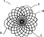
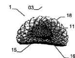
The invention relates to an implantable device (1) which is used in human body and/or animal body for plugging and/or partly plugging defective openings (2), inner cavities, an organ channels, etc. or for providing a limited connection opening among walls, organs, the inner cavities, etc. The implantable device (1) comprises a bracket structure (17). The length of a first shape of the bracket structure along an axis (x) is larger than a transverse range, and the length of a second shape of the bracket structure long the axis (x) is smaller than the transverse range, wherein the bracket structure (17) is provided with a proximal section (10) and a distal section (11), and takes a type of a filling yarn and/or knitmesh and/or sandwich cloth and/or silk net; at least one part (11) of the second shape is provided with a first sub-portion (14) back to another part (10) and forms a second sub-portion (13) at least in a double-layer configuration; the second sub-portion (13) firstly unfolds from the first shape into the second shape and then bends backward to the first sub-portion (14) along the direction toward the another part (10).
Description
Technical field
The present invention relates to the implantable device (implantable device) of use in a kind of human body and/or the animal body, be used for shutoff or the damaged opening of part shutoff, chamber, organ passage etc., or between wall, organ, chamber etc., provide and limit UNICOM's opening, it comprises carrier structure, first shape of this structure is that its axial length is longer than lateral length, and that its second shape is its axial length is shorter than lateral length; Wherein, this carrier structure has close end and distal portion, and with weft yarn (weft) and/or knitmesh (mesh) and/or interlayer cloth (layered cloth) and/or silk screen forms such as (gauze) formation.
Background technology
Axle typically refers to the longitudinal axis of implantable device, and this implantable device is along the shaft extension exhibition.People can recognize this implantable device from prior art.For example, patent DE 103 02 447 A1 have disclosed this implantable device, and wherein, the near-end of second kind of form and/or distal portion are roughly plane, disc or loop configuration, and outwards bend from the interlude that connects far-end or close end, be centered around around the inner space.Accessory fibers or knitmesh part as film structural component can be combined in the implantable device.The use of this film structural component means that for example the damaged opening at human heart position can obtain shutoff.Organizing also of this position may be grown.
DE 100 00 137 A1 have also disclosed a kind of like this implantable device, are used for the shutoff of damaged opening in human body or the animal body.Wherein, its second kind of form presents the form of approximate Double disk, i.e. near-end disc-shaped component and distal circles discoid component are used for holding the peripheral region of damaged opening between two disc-shaped components.This carrier structure is the integrated member that does not have seam basically, and its part by the pipe that blocks is made.Equally, also film can be set in implantable device, this film is located at the not ipsilateral of implantable device, perhaps even can be enclosed within on the implantable device as tensile " socks ", should " socks " have some respective openings for the delivery system use.
In addition, DE 103 38 702 B1 have also disclosed corresponding a kind of implantable device, wherein, are provided with the column limbs between near-end and far-end retaining zone, and near-end retaining zone wherein is towards the proximal openings formula.The end of the tinsel of the far-end retaining zone of implantable device or silk is fixed together by clamper.In addition, braiding inlay (weave inlay) can be set, with complete shutoff isocon (shunt) in column limbs or near-end retaining zone.
In addition, also have the implantable device of other type, for example US No 5 846 162 and US No 5 725 552 are disclosed, and the two all adopts bell configuration.WO 93/13712 has also introduced the implant that is used for shutoff septal defect (septumdefects), and it presents bicone or two disk configuration under implanting state, and in this case, external structure is to be formed by not direct-connected filament member.They are by the materials for support of sail shape portion (sail portions), and wherein, sail shape portion is sewed together with the damaged radius corresponding to wanted shutoff.The defective of this system is, because implant adopts a large amount of members to form, assembling is very complicated, and cost is also high.
WO 95/27448 has introduced a kind of implant as vein filter, also is used as the bearing carrier of septal defect blocking device simultaneously.In this was provided with, a series of independent filaments formed a kind of elongated relatively bicone, and simultaneously, in one embodiment, these cones are pointed to toward each other with the form of bone, and in another embodiment, described cone direction is identical, is similar to an Amanita muscaria.
US No 5 433 727 A have disclosed big damaged implant in a kind of shutoff heart, such as interatrial septum damaged (ASD) or ventricular septal defect (VSD).In this case, shield (screen) is placed on the place ahead of septal defect, and pass damaged fixing with corresponding stopper, this stopper is actually by four end ring and constitutes, each end ring is again to make with a respective metal silk, in a single day these end ring leave conduit and just launch immediately, and can be used to prevent that implant from sliding into shield place one side.The shutoff implant also comprises an expandable type foamed resin disk, and the latter comprises " X " shape coating silk skeleton that is applied on the foamed resin disk again, and is located at an adjustable collar of skeleton central authorities.
WO 97/28774 has disclosed a kind of implant, and in a single day this implant leaves conduit, launches automatically with regard to relying on second shape that it had, and cooperate damaged size on a large scale under the effect of elastic force.This implant infrastructure is clamped at damaged both sides with the double-disc type formula, is resisted against damaged peripheral region.Implant is formed by a series of metal silk members, and these thread members adopt suitable method of attachment (such as ultra-sonic welded or soldering) to link together.Also be provided with the covering that is fixed on the wire member will on the implant.
In addition, WO 99/12478A1 has also disclosed a kind of corresponding implantable device, is provided with knitmesh in this apparatus, and its nitinol alloy wire that interweaves by several dumbbells or yo-yo shape is formed.The rounded knitmesh shape of first shape of implantable device, the two ends of this knitmesh have the silk end that scatters, and the latter respectively is fixed subsequently and is welded in the sleeve pipe.The implantable device of this kind structure respectively has outstanding sleeve pipe at its nearside and distally.
US No 2003/0191495 A1 has disclosed a kind of interval stopper (septum occluder), and it has near-end anchorage element and far-end anchorage element, is connected by connecting elements between the two.
Other patent, for example, US No 5 108 420 A, DE 42 22 291 A1, DE 28 22 603A, WO96/01591 and EP 0 474 887 A1 have introduced the other implant and have put the conduit system of this implant.DE 695 29 338 T2 have also introduced a kind of blood vessel internal filter device, and it has by the dome-shaped shield that keeps rope (holdingcables) to form.
Disclosed all implantable devices can shutoff be damaged effectively to a certain extent in the above-mentioned prior art, especially when it uses film structural component.Yet, it should be noted only have all these implantable devices that just can suitably use can be for the unfolded enough space of implantable device the time in the prior art in the corresponding zone of implanting.But, exactly,, be very limited for implantable device implantation or unfolded space in the left atrial region of heart.
Summary of the invention
Therefore, the objective of the invention is, the described implantable device of a kind of characteristic as claimed in claim 1 is proposed, this apparatus can be complementary with human body and/or the intravital position of inserting of animal, because carry out the space of implant surgery at these positions very limited, such as the left atrium of heart, yet, this implantable device still has good stable, unexpected displacement can not occur after implant surgery; In addition, the present invention also provides a kind of method of launching this implantable device.
This purpose can realize by the described implantable device of the characteristic of claim 1 of the present invention.Wherein, at least one part of second shape has the outside first sub-portion of another part dorsad, and forming the second sub-portion that is at least double-deck configuration, the latter at first expands into second shape and is folded into the first sub-portion backward along the direction towards another part from first shape.
This purpose also realizes that by implantable device is expanded into the second shape method from first shape wherein, a) implantable device is set to the first elongated shape in conduit; B) implantable device is discharged from conduit expanding into second shape, and second to be shaped as the length of implantable device littler than lateral extent for this; C) the sub-portion that at first is discharged from the implantable device first of conduit is unfolded, and when being discharged from conduit with contiguous another sub-portion of this sub-portion of the first of implantable device, this sub-portion bends backward along the direction towards conduit; D) implantable device is in case after further being discharged conduit, just launch fully.Further feature of the present invention limits in the dependent claims.
For this reason, implantable device proposed by the invention only needs very little implantation space, because when implantable device when implant site is discharged from corresponding pipe, usually just slightly discharge from conduit at far-end, the sub-portion that is at first discharged bends along proximal direction, and, when implantable device further is discharged from conduit, the sub-portion of the distal portion of discharging subsequently with this sub-portion contiguous quilt is unfolded, and the latter is towards far-end.When implantable device was further discharged conduit, the sub-portion that at first is discharged from was folded in another height portion backward, like this, had just formed the double-deck configuration that is bent toward each other by two sub-portions.This bilayer configuration is with respect to the monolayer configuration apparatus in the prior art, and the intensity of this part of implantable device obviously increases, and like this, just can provide firm especially base at implant site.In addition, also find to compare with the apparatus of prior art, this double-deck at least configuration is also more favourable upon deployment, because implantable device can directly launch fully upon deployment, even so when this apparatus not in complete deployed condition following time, also can shutoff need the big opening of shutoff, the risk that apparatus slips over opening can not occur.
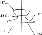
In implantable device is located at damaged opening, in the time of for example on the heart wall, place between close end and the distal portion and pars intermedia that the relative close end of diameter and distal portion diminish passes damaged opening or heart wall, in case implantable device is further discharged from conduit at damaged opening or heart wall near-end, the close end of implantable device has just launched.
Because two sub-portions of an above-mentioned part (particularly distal portion) bend backward and toward each other, when implantable device is discharged from conduit, only needs very little space just can make at far-end and especially accurately and implant (for example) heart left atrium with mating according to implantable device of the present invention.
The characteristics of at least one part (especially close end) are to present disc or protrusion configuration basically at its marginal area.In general, two parts all are similar configurations.In addition, a part can be a disc, and another part then can be to protrude configuration.Be characterized in that is partly with the basic closed carrier structure in end.Particularly, carrier structure has constituted the close end that combines at near-end, and close end is located at the outside with respect to implantable device.Should also can place in the sleeve component basic closed end, and the weft yarn of carrier structure and/or the end of knitmesh and/or interlayer cloth and/or silk screen are combined.It also can adopt other certain form to combine.
Implantable device also can be the rack form that has the end, and roll over toward each other this end, is double-deck configuration.The specific of this configuration is that the second sub-portion is folded into the first sub-portion backward to inside.
At the implantable device that is used for the intravital damaged opening of shutoff or part shutoff human body and/or animal, inner chamber, organ passage etc., it comprises carrier structure, this carrier structure can convert second shape of flattening from first shape to renewablely, wherein, carrier structure has close end and distal portion, and constitute by weft yarn and/or knitmesh and/or interlayer cloth and/or silk screen, and, one of them part is outside opening mode, and another part is the closing form of projection, particularly is enclosed in the sleeve component; Characteristics with this part of opening mode are that it has at least two sub-portions, and they bend toward each other and are double-deck configuration.
If the close end of implantable device is disk-like configuration basically, then is particularly suitable for being applied to (for example) wall, and implantable device is inserted in this breach around damaged opening.Particularly when implantable device is arranged on the implant site of slight curvature, the protrusion configuration of close end can also guarantee that implantable device is in the good hold from the implant site of proximal direction.When adopting this protrusion configuration, the close end of implantable device can combine effectively, so that the size of the through hole that may pass for implantable device is dwindled as far as possible.This also can constitute the plugging device of opening.In general, a through hole also can be set on implantable device.The other above-mentioned sleeve component of plugging effect (for example) also can be installed in the proximal end of the implantable device that combines if desired.
Because the double-deck configuration that bends in opposite directions backward each other of distal portion, thus special good stable can be obtained, thus can realize the especially firm hold of implantable device at implant site.Implantable device is crucial especially in the accurate expansion of remote area, because remote area is not to be easy to be entered by near-end, (for example) so-called Naja effect may take place in this, promptly, implant is abnormal to be launched, but occurred being folded into together, to the situation of a lateral bending song, just as elapid head.At this moment, it is highly important that implantable device launches very reliably with desired shape.Under very big situation, to one side intervention of far-end of implant site be very difficult because can only enter the far-end implant site by damaged opening from proximal direction (for example).For this reason, so that the implantable device of far-end one side obtains the part enhancing, just can provide special good stable by portion of terminal far away is bent toward each other, and guarantee that implantable device launches at far-end in a suitable manner, this is verified effective especially.
The double-deck configuration of distal portion has been realized the stability of edge of the encirclement implant site (such as damaged opening) of implantable device, therefore helps implantable device in the storing of implant site and fixing.The second sub-portion along the distal portion that bends backward towards the close end direction is preferably narrow shape, is and extends the thin edges form on every side, because can make required length of run shorter like this, thereby makes the required space of implantable device expansion littler.In addition, mode or conduct are wherein a part of as an alternative, can extend to or near the pars intermedia between close end and the distal portion, particularly can be resisted against on the pars intermedia along the second sub-portion towards the distal portion that the close end direction bends backward.By this set, rely on the double-deck configuration of distal portion, just can in the gamut of the sub-portion of distal portion, realize stable at far-end.In addition, (for example) the second sub-portion that rests on human or animal's heart wall can form Elastic Contact with heart wall, itself or by with whole distal portions slight curvature or be the arch configuration, perhaps by relative another sub-portion of at least one height portion with distal portion, by self the overlapping setting of predetermined space, produce described elastic reaction, realize and stable especially the cooperating of implant site.
The characteristics that are located at the diameter of the pars intermedia between close end and the distal portion are, this diameter is with respect to close end and distal portion and/or extend through the diameter of implantable device through hole, size all is predetermined, so that UNICOM's opening of qualification to be provided between human body and/or the intravital wall of animal, organ, inner chamber.Therefore, passing the through hole of implantable device or the size of the pars intermedia between implantable device distal portion and the close end can be set to, and UNICOM's opening of desired qualification can be in human body or animal body be provided between two ventricles, inner chamber, wall, organ etc.
The specific of the distal portion of implantable device is that it can not rely on close end and just can launch.Especially, distal portion can be launched fully, and does not rely on close end.Like this; just can shutoff relatively large be damaged; and use the implantable device of prior art for those; this is impossible realize; because after big defect area is put the implantable device of prior art in human or animal's heart; to right side of heart, the result can not play a role through regular meeting's slippage for it.
Can at least one film structural component be set in the zone between close end and/or distal portion and/or close end or the distal portion.Film structural component can adopt suitable manner (for example by making or glued or other certain mode) to be fixed on weft yarn, knitmesh, interlayer cloth or the silk screen of implantable device carrier structure.Fixing can finishing by making in the carrier structure outer edge region easily between film structural component and the carrier structure.Particularly, can pass around the edge of film structural component and the edge side that passes carrier structure forms ring, and beat at least one at carrier structure edge ring place and tie film structural component is fixed on the carrier structure with wire-like members.Not only can provide firm fixation at edge sewing film structural component and carrier structure, and can make that carrier structure is covered by film structural component easily fully, not have the risk of film structural component slippage.Film structural component can present real knitmesh form, and each silk thread of film structural component is all connected together, and prevents that silk thread from producing displacement.This configuration of film structural component means, can promote the formation of epithelium, prevents the generation of thrombosis.Can between the leg section that forms by carrier structure and be provided with, insert at least one film structural component by multilamellar.Leg section can be arranged on the middle section of implantable device, so that film structural component is presented to this zone easily.
Further find, if the size of the size of film structural component and the damaged opening that needs shutoff is roughly quite the time, with highly beneficial.For example, rely on this double-deck at least configuration towards the distal portion (having two sub-portions) of close end and sensing backward, just can in such a way film structural component be fixed on the implantable device, promptly it covers the left side of the heart in the damaged open area fully.Like this, form blood clotting and cause thromboembolism that there is very little risk in the knitmesh of implantable device carrier structure, and in prior art, in conjunction with as the film structural component of implantable device the time, risk is then bigger with polyester and nickel-titanium alloy material.Because in this case, polyester and Nitinol are pushed in the zone of the wall that centers on damaged opening mutually, cause blood clotting, also can cause the generation of described complication on some professional journals, such as headache or even temporary blindness.When using implantable device of the present invention, because film structural component size of the present invention is corresponding to damaged opening, thereby just these complication can not take place.
Find that further film structural component is fixed to advantageous particularly on the implantable device as follows, film structural component roughly is the damaged size that needs shutoff in second shape of implantable device.Like this, film structural component just can be to be fixed on the implantable device with hole that needs shutoff accordingly or the right size of the identical Buddhist of damaged opening exactly.Like this, the size of employed film structural component just can be as much as possible little, and this is very favourable, because the size of film structural component has been dwindled, agglomerative risk has also just reduced.Like this, at damaged parameatal edge, human or animal's heart wall for example, only a knitmesh or the silk screen with the implantable device carrier structure centers on, rather than adopt and to have the knitmesh of film structural component or the combining form of silk screen, thereby greatly reduce the risk of blood clotting.
Adopt such size if find film structural component, and be fixed to as follows on the implantable device advantageous particularly, be that film structural component has covered implantable device basically fully in second shape of implantable device, and particularly covered distal portion basically fully.This discovery can reduce the risk of blood clotting especially effectively.Proved at left side of heart useful especially because blood flows to human or animal's brain from left side of heart, so blood clotting can cause extrahazardous consequence.Blood flows to pulmonary from human or animal's right side of heart, and blood clotting can be filtered and dissolve in pulmonary, so, can not cause above-mentioned adverse consequences.
Will be appreciated that in the implantable device and can use several film structural components simultaneously, thereby significantly improve the shutoff selection mode of implantable device on need shutoff opening.In addition, the density of the node configuration of implantable device carrier structure (silk screen, interlayer cloth, knitmesh, weft yarn etc.) can be very big, so just can no longer need film structural component, and the carrier structure of implantable device itself then can have the function of this film structural component.In this case, the node configuration of implantable device carrier structure intensive big is enough to make carrier structure can play the effect of film structural component.
The carrier structure of implantable device can be by (for example) shape-memory material, especially metal or metal alloy, particularly Nitinol, and perhaps plastic material is made.If be provided with film structural component, it is by plastic material, and especially polyester or another kind of polymer are made.The characteristics of the carrier structure of implantable device are that it is formed by single thread member.Yet, also can adopt several thread members to make.Like this, carrier structure just can be by single, two or two thread members that twine, three, three braidings, and particularly nitinol alloy wire is made; Or a plurality of windings, stranded or the braiding thread member, especially nitinol alloy wire is made.In addition, carrier structure also can mutually combine by above-mentioned various materials and form.Proved and particularly advantageously be, in this configuration of implantable device, implantable device is not in case present above-described Naja shape from the conduit discharge, in this example system that adopts prior art about its different structure configuration, this Naja shape can be brought a lot of problems, particularly when relating to the relatively large implantable device of use.The carrier structure of implantable device can adopt fiber (particularly polyester fiber) braiding to form.The carrier structure density of this fibrage is bigger, is particularly suitable for the implantable device of rack form or is used for replacing independent film structural component.
If the carrier structure of implantable device (silk screen, knitmesh, weft yarn, interlayer cloth etc.) only is made of single thread member, this means and between each single thread member, do not need the connecting portion that welds, corrosive any risk can appear so hardly, and, also needn't worry fracture to occur, and phenomenon of rupture will occur in the welding position.And corrosion and connecting portion can cause the fault of implantable device, even can injure patient, or lead to complications after implantation, perhaps also may produce fracture during implant surgery.These problems of running in the prior art then no longer appear in the implantable device that proposes according to the present invention.
At least one rhizoid shape element cross-section can be any combining form of circular or straight shape or straight shape and circular cross section.In addition, the carrier structure of implantable device can be established one or more end ring or eye thimble in the end.Can join with stranded or interlacing part along the end ring on the direction of carrier structure remainder or eye thimble, thereby when the density of knitmesh or silk screen diminishes, partly realize stability greatly.Advantageously, the end of a thread member is woven on the surface of carrier structure together.Adopt this configuration, tinsel can not stretch out carrier structure from the end and injure blood vessel or tissue around the implant site.
Advantageously, the carrier structure of implantable device also comprises and is woven together mutually or is woven into stranded thread member on certain part, and these parts are the braidings or close the form braiding that member passes mutually to tangle and form separately at the place, cross point of thread member.This carrier structure of implantable device can comprise one or more thread members that are woven together, and wherein, the various piece that thread member forms also can twist together, thereby they also are defined as a pair of member.When paired thread member that employing twists together, each independent thread member passes independent of one another at the place, cross point and weaves, and perhaps, whole a pair of member passes another member is woven.A kind of variation pattern in back is, two thread members or round another member is woven by two parts that thread member twists together.When adopting corresponding manner, also can will knit together than the thread member of crin thigh or the part that thread member is formed.To thread member or carry out twisting by the part that thread member forms and mean and to guarantee high stability, paired stranded members is woven the position that then means each paired thread member in the carrier structure with ad hoc fashion can be fixed, thereby just can not make the unexpected hole that the different size size occurs on the carrier structure because acting on the monolateral pulling force on the implantable device.
In monolayer, bilayer or multilamellar configuration, carrier structure can be formed by at least one thread member.This not only can increase the stability of carrier structure, and also can increase its density obviously, thereby even in that do not have can the damaged opening of shutoff under the situation of film structural component.
Each layer of carrier structure can be made of same material or different materials.For example, one deck at least wherein comprises Nitinol, and another layer comprises polyester at least, also has one deck to comprise PTEE (politef) at least.Like this, just can produce carrier structure, and can partly have varying strength with desired stability.In addition, can between two-layer at least, at least one film structural component be set.This film structural component can be fixed between these layers of this carrier structure firmly.Advantageously, the selection of film structural component material can and its each layer of carrier structure between material be complementary.
Implantable device can be concentric shape or eccentric shape.Advantageously, the carrier structure of implantable device can be automatically and the shape of implant site be complementary, at least one height portion of an one part when second shape along bending backward towards another part direction.Especially the implantable device distal portion special shape that sub-portion bends backward, make implantable device or its carrier structure not have fixed center, thereby it is any type of damaged that implantable device can be adapted to neatly, perhaps adapts to damaged by second shape that it had.For example, if damaged opening is oval, implantable device also can present ellipse, so just is particularly suitable for good fit with damaged opening.In addition, the adjacent wall that it also can adapt to implantable device easily and is leaned on, in this respect, the double-deck part (for example far-end) at least that implantable device relies on the subdivision of bending backward and forms therefrom, and realize solid and reliable especially hold at implant site.Usually, also this situation can occur, promptly need the damaged opening of shutoff to be positioned near the aorta.Implantable device also can be easily be complementary with the shape of damaged opening and its peripheral region (being aorta wall) in any direction.Implantable device can also cooperate the damaged opening at following position in the corresponding way, for example, and pulmonary artery zone, atrial septum wall, coronary sinus, pulmonary vein and around the shape of lobe edge structure (especially wall).
Perhaps, the shape of implantable device can be made the shape that cooperates implant site.Because the far-end of second shape of this implantable device and/or close end are shaped (especially prebuckling) in advance, so implantable device can launch with the shape that implant site is complementary.Particularly, this can be avoided aorta is exerted pressure, and implantable device is located in its next door.Otherwise, acting on Supraaortic this pressure and can cause aortic perforation, this can bring life-threatening consequence to patient.Particularly, when using the heat treated carrier structure of also process that constitutes by shape-memory material, can make implantable device and implant site shape reach Optimum Matching, and make implantable device have second shape.Thereby especially have this part that bends sub-portion backward and form the carrier structure of double-deck at least configuration and can further help this coupling, because double-deck configuration makes that second configuration that implantable device had is stable further.Because the use of this shape, thereby can get rid of the risk that this particular configuration of meeting changes shape basically.A second given configuration can be provided in advance, described configuration even applicable to the most abominable situation of the damaged open area that needs shutoff, like this, thereby irremediable patient also can obtain medical treatment because the aorta damage is dangerous so far.In all patients ASD more than 30% owing to worry the damage aorta wall or damage near the damaged opening other wall or structure and can not adopt the implantable device treatment of selling in the market, because risk is too big.Because second shape of implantable device has this advantageous feature that is complementary with implant site, oppress or damage aorta wall or need other wall of damaged opening adnexa of shutoff or the risk of structure no longer to occur, like this, these patients just can be treated.Rely on an one part to have the configuration of double-deck at least sub-portion, the configuration that is complementary with implant site of this implantable device not only can not change, and can keep suitable stablizing on the contrary.
Advantageously, at least one member is as visable indicia, is used for visually indicating implantable device during the implant surgery under surveillance equipment.This at least one member is little helical member, is located at the edge of implantable device.This spiral component partly twines its edge of implantable device.At least one member preferably includes an X-light visual material, particularly contains 70-90% platinum, 30-10% iridium.Should understand, can also use other material, these materials also should be able to visually be indicated implantable device under surveillance equipment.
Because special configuration that implantable device of the present invention had, this implantable device can with the MNR compatibility, thereby, can not cause that implant surgery monitors problem.Like this, during implant surgery, particularly by formation method, such as X-ray represent, echography (echography), scintigraphy (cintigraphy) wait and follow the tracks of implantable device.If as prior art, on the high-quality steel wire, the welding position is arranged, will produce artifact when using formation method, and these artifacts can cause problem in following the tracks of the implant surgery process.
Can be seated at any angle by suitable discharge system in the damaged opening according to implantable device of the present invention, implantable device can suitably be complementary with this implant site then or firmly place.In order to cooperate the implant angle of implant site, this implantable device can be provided with pars intermedia, and this pars intermedia can be crooked at any time, particularly is straight pars intermedia and/or is inverted pars intermedia and/or folding accordion configuration.Also can with the various piece of implantable device each other integral body interweave, advantageously, two halfbodies of implantable device or the junction of various piece are positioned at pars intermedia, so that there bending arbitrarily.Discharge of the present invention system is design like this, and promptly implantable device can be driven to rotate with the discharge system, particularly by keeping silk to drive relative seal wire or discharging the silk rotation.Particularly discharging silk ribbon has very tiny silk end, its diameter at about 0.1mm between the 0.3mm.Like this, just can at an easy rate this discharge silk be passed the implantable device carrier structure, even the latter's mesh density is very high.Keep silk ribbon to have at least one to be used for passing the end ring of discharging silk.In order to be fixed to easily on the implantable device, keep silk can pass the end ring of implantable device carrier structure.Like this, just can on the implantable device carrier structure, provide firm especially retentivity, in implant surgery, can keep stable and guiding.Mode as an alternative perhaps as append mode, keeps silk can pass the supporter ring that the end ring with implantable device connects together.
Implantable device can rotate around at least one discharges silk and at least one maintenance silk and be floating.Like this, just can be in human body or animal body in addition the position that is difficult to enter realize accurately location.
The method of using this discharge system that implantable device is discharged at human body or the intravital implant site of animal is, ring that at least one end that keeps silk to be passed in the implantable device carrier structure is provided with and/or the supporter ring that passes the ring that is used to connect the end that is located at the implantable device carrier structure, and keeping forming end ring on the silk.In addition, discharge silk and pass end ring and the implantable device that keeps silk, discharge on the silk thereby keep silk to be fixed to.Subsequently, discharge silk passing conduit and to arrive implant site along discharging silk and keeping silk to push together, thereby implantable device is launched at this place with implantable device.In order to discharge implantable device, will discharge silk and pull back, and extract out from the end ring position that keeps silk along proximal direction, keep silk then from the ring of implantable device, to extract out, and pass conduit and pull back.At this moment, for ease of the propelling movement action, discharge silk and maintenance silk can be arranged in the interior sheath member of conduit.
Because implantable device can rotate with the discharge system, so various difform hole or damaged opening can obtain complete shutoff.Therefore, even when implantable device is eccentric configuration, the turning power that relies on the discharge system to provide also can realize accurate placement, therefore, when the space of a side is very little, this eccentricity helps definite setting, for example aorta near zone or other boundary shape, for example human or animal's heart wall.
Because seal wire or the characteristics of discharging silk are that the silk end is very thin, diameter specifically at 0.1mm between the 0.3mm, for this reason implantable device and discharge silk also can be floating together.If the position of implantable device is not very desirable, this implantable device still can be discharged by conduit, although it is in the free floating state.On the contrary,, then can discharge from conduit, need not change the residing good locations of implantable device with the discharge system if the implantable device present position is fine.But this situation can not be accomplished in the discharge system that is used for implantable device of prior art.The advantage of discharging silk is that the silk end that it curls can prevent from implant site is damaged.
Although it is the double-deck configuration with two sub-portions that can bend toward each other that the front has been introduced the advantage of distal portion, will be appreciated that, also close end and two parts of distal portion all can be designed to above-mentioned pattern.Equally, also can be with part with two sub-portions that bend toward each other with corresponding manner be provided with the same with close end.
In addition, be used in human body or animal body shutoff or the damaged opening of part shutoff, inner chamber, organ passage etc. or be used between wall, organ, inner chamber etc., providing the implantable device of UNICOM's opening of qualification can be provided with carrier structure, this carrier structure is first elongated shape and second shape shorter than the size of first shape, wherein, carrier structure has close end and distal portion, and form in the mode of knitmesh and/or interlayer cloth and/or silk screen, wherein, at least one part of carrier structure is that shape winds up in the shape of a spiral.In addition, two of carrier structure parts can the helical form mode wind up.In fact, the part that winds up in the helical form mode makes carrier structure become more stable in this part, and if this part just is bent to form double-deck configuration toward each other by two sub-portion, then do not reach so stable.Part in second shape formation, longitudinal extent with respect to implantable device forms horizontal helical or helical form automatically, obviously this part is more stable than helical member known in the prior art and that formed by thread member, has especially used the carrier structure of being made up of silk screen, knitmesh, weft yarn, interlayer cloth form.In addition, pack into especially easily very thin conduit and in described conduit, discharging equally again of implantable device.Finally constitute helical form owing to launch backward repeatedly, thereby the size of second shape of implantable device can be very big.
Advantageously, at least one part that winds up with helical form has several towards the sub-portion of relative another part and several sub-portion of another part dorsad.The quantity of those sub-portions that bend toward each other of helical form part can be chosen as any amount.For example, can establish towards another part be two sub-portions, and be two sub-portions back to this part.The stability of helical form part is determined by the quantity of selected subdivision.
This part that another part can wind up with the helical form mode is identical configuration or isomorphism type not.Particularly, two parts can bend in the helical form mode, and the bending degree of one of them part can be less than another part.
If two parts are not to be provided with by the form that the helical form mode bends, so, this part that bends by the helical form mode can not be flat type basically and/or protrude and/or curved configuration to small part.When the related flat shape that is configured as, this part (for example) can be straight ended (for example cylindrical midsection) form between disc or two parts.Protruding configuration to small part also can combine with curved shape.On the contrary, curved shape also can be essentially disc.These two parts can also adopt different-diameter.
Part with the bending of helical form configuration has through hole usually.Another part also can have through hole, but also can be basic closed form.In general, if highly beneficial under special environment for use, also could be at the end mounting sleeve member of (being closed configuration) that combines.
In addition, at least one film structural component can be packed into or is fixed at least one helical form bending part and/or the other parts.In general, two parts also can the helical form mode self bend, and also can all use film structural component on one or two part.
In addition, be used in human body or animal body shutoff or the damaged opening of part shutoff, inner chamber, organ passage etc. or be used for providing the implantable device of UNICOM's opening of qualification can be provided with carrier structure between wall, organ, inner chamber etc., this carrier structure is first elongated shape and second shape short with respect to first shape; Wherein, carrier structure has close end and distal portion, and with knitmesh and/or interlayer cloth and/or web form formation; Wherein, at least one part of second shape comprises two sub-portions, and one of them sub-radicals by which characters are arranged in traditional Chinese dictionaries expands into second shape from first shape earlier, and along being folded into the second sub-portion with the opposing direction of another part, this second sub-portion points to described another part.So advantageously, the curved sub-portion that comes bends inwards in the implantable device backward.In addition, rely on the sub-portion of this bending, just strengthened the stability at the edge of part or particularly this part.Compare (as previously mentioned) with a sub-portion that outwards bends backward, if implantable device can be withdrawn in the conduit after launching once more, the sub-portion that bends inwards can not be bent into first shape backward, perhaps, at least almost can not be bent into first shape once more backward.Therefore, implantable device is in case be difficult to adopt this embodiment to withdraw after implant site is discharged.
When adopting the configuration that bends inwards of a sub-portion, the straight microscler interlayer cloth or the silk screen of carriage mechanism can properly be strengthened in the end.So just be particularly suitable for production of machinery, because carry out the making of straight elongate structure with machine than easier by hand.Yet manual at least more effectively production size is the implantable device of short very complex configuration.
Implantable device according to the present invention is particularly suitable as damaged, the left ventricle in function atrium that vascular plug is used for shutoff interatrial septum damaged (ASD), ventricular septal defect (VSD), patent foramen ovale (PFO), heart, that is to say, described vascular plug is to be used for the peripheral vessels plugging system of running system on every side, be used for the treatment of aortic aneurysm, also can be used for treating PDA tumor (PDA).Particularly, the double-deck configuration of at least one part of implantable device can provide stability to a certain degree, like this, can shutoff even larger sized passage or opening by using this apparatus, particularly greater than 10 to 12F opening.
Use implantable device in order to go up in PDA tumor (PDA), implantable device preferably makes the medicated cap configuration, and its shade partly is at least one double-deck configuration.This medicated cap configuration makes the medicated cap head portion of implantable device can enter in the PDA tumor (PDA), thereby it is carried out shutoff.This shade portion is resisted against on the aorta wall, so that aorta keeps free state.
In addition, if when double-deck shade portion has the sub-portion of at least two of bending toward each other, this mode is very favourable.Adopt this set form, that part ofly have special stability with aorta wall offsets, thus can be provided with very firmly firm.The shape that is resisted against the shade part on the aorta wall so just can be very reliably attached on the aorta wall preferably corresponding to aortal flexibility.Yet, because two sub-portions of shade shape part bend toward each other, so this part can and can be fixed on the aorta securely from aortal shape movingly.Because the sub-portion of this part is bending toward each other backward, and other structure of medicated cap shape, also can the bigger hole of shutoff diameter difference with same implantable device.For example, for the hole of diameter 8mm, be used for the shutoff diameter and also can carry out tight shutoff it less than the medicated cap shape implantable device of 3mm hole.Therefore, the use motility of this medicated cap shape implantable device is very high, and same, the configuration of medicated cap shape is also very special.
The head portion of the implantable device relative with shade shape part, the inside of the implantable device that can bend inwards especially.For this reason, this part can be closed and not outwards be protruded the end when being shaped, thus at the place, end, not only can make this part keep dimensionally stable at an easy rate, and the end of not stretching out implantable device.
Another kind of mode is that the head portion of the implantable device relative with shade shape part can be folded to the outside and stretch out from implantable device, so head portion just forms water droplet shape.This shape is particularly suitable for being inserted in the blood vessel.
As an advantageous feature, be used for launching the unfolded method of implantable device according to of the present invention, be folded to another height portion along the subdivision that bends backward towards duct direction with tiling basically.In addition, as previously mentioned, along the subdivision that bends backward towards duct direction can be around himself in the shape of a spiral the shape mode twine.When implantable device was discharged from conduit, the implantable device configuration of other above-mentioned shape also can be used as second shape and launches.In addition, at least one part of implantable device can be balloon-like or be the shape that the anchor shape stretches out, and particularly, it has the sub-portion in the implantable device that bends inwards.In addition, at least one part of implantable device can be smooth basically and/or can be to protrude or recessed configuration and/or can be crooked the protrusion and/or concave shape to small part.Also can adopt the mixed form of above-mentioned shape, and can select dedicated mode, as the size of the various piece of implantable device.
If at least one surface of implantable device (particularly carrier structure and/or film structural component) is when applying or handling with at least a functional material, this is very favorable.For this reason, particularly, the usefulness of implantable device still can further be improved, and this is avoided because of the side effect meeting on the body part that acts on implantable device on the one hand, and on the other hand, drug treating then can directly be passed through in the zone around the implant site.Especially, the functional material of the coating on implantable device or implantable device surface or processing usefulness can be selected from following material group, as inorganic material, ceramic material, synthetic polymer, human biopolymer, medication coat, drug release polymer, biomolecule, functional group and hereditary material.In this respect, can use and be used in combination one or more materials, the material that particularly has the combination of various usefulness or function.
Functional material is preferably chosen from following material: gold, biological gold, diamond-like-carbon (DLC), diamond-like nanocomposite material (DLN), yttrium oxide, nanoporous Al
2O
3Carborundum, hydroxyapatite, titanium oxynitrides, polychlorostyrene is for xylol, polybutyl methacrylate, phosphocholine, polyethylene, polyethylene ethylene acetic acid, the own ester of polymethylacrylic acid, poly-[two] (trifluoro ethoxy) phosphorus nitrence, politef, polyurethane, collagen, chondroitin sulfate, elastin laminin, fibrin, hyaluronic acid, abciximab, heparin, TAXOL, discharge the cellulose of abciximab, discharge the phosphocholine of angiogenic peptide, the polyethylene ethylene acetic acid or the polybutyl methacrylate of released dna, discharge the poly-L-lactide of medicine, the polylactic acid of paclitaxel or hirudin or delivery of prostacyclin, polylactic acid-the Phosphorylcholine of releasing virus carrier, the polyurethane and the stem cell of release forskolin.For example, in this respect, can be with yttrium oxide as surface passivation or ORC.For example, polyurethane can be used with thin form.In being referred to as the molecular surface engineering, also can further provide the functionalized surface that adopts biomolecule and functional group.That is to say, adopt functional group to form the molecular material surface.In addition, the surface of implantable device can be adopted the cell ligand structure consciously, is used for the adhesion of the CFU-GM of blood internal recycle.Poly-L-lactide can combine with multiple medicine, cytostatics base medicine particularly, thus can use the medicine of any kind of that can finally obtain the expection therapeutic effect.For example, for the structural damaged or structural heart defect of shutoff heart of patient, such as patent ductus arteriosus (PDA), particularly, with bonded material of polymer phase or medicine can be the material of accelerating endothelialization, that is to say, accelerate the growth of the peculiar cell of health.
The surface treatment of implantable device can use various processes to carry out, such as processing such as Cement Composite Treated by Plasma (being used in particular for DLC (diamond-like-carbon) or DLN (diamond-like nanocomposite material)), PVD (physical vapour deposition (PVD)) method, CVD (chemical vapour deposition (CVD)) method, ion implantation, cathodic sputtering, ion beam, laser technology, thermal process, spin coating, dip-coating, etching and electrobrightenings.
Description of drawings
In order to illustrate in greater detail the present invention, below in conjunction with accompanying drawing, at length introduce embodiments of the invention comprehensively, accompanying drawing is as follows:
Figure 1A is the plane graph of implantable device first embodiment according to the present invention;
Figure 1B is the plane graph of implantable device second embodiment according to the present invention;
Fig. 1 C to Fig. 1 F is the fragmentary detail view of implantable device shown in Figure 1B;
Fig. 1 G and Fig. 1 H are for being provided with the side sectional view of implantable device shown in Figure 1A at the heart wall place;
Fig. 1 J is the plane graph of implantable device the 3rd embodiment according to the present invention, and this embodiment has large through-hole;
Fig. 1 K is the axonometric chart of the 4th embodiment of medicated cap shape implantable device according to the present invention;
Fig. 2 A to Fig. 2 C shows the fragmentary detail view of monolayer, bilayer and the three-decker configuration of the carrier structure of implantable device according to the present invention;
Fig. 2 D, Fig. 3 and Fig. 4 show the single layer structure configuration fragmentary detail view of the carrier structure of the implantable device according to the present invention, this carrier structure have thread member interweave right;
Fig. 5 to Figure 13 shows the fragmentary detail view of the various weaving manners of carrier structure of formation implantable device according to the present invention;
Figure 14 to Figure 16 shows the fragmentary detail view of plane graph and this implantable device middle section and the marginal area of another embodiment of implantable device according to the present invention;
Figure 17 is the fragmentary detail view of kink backward;
Figure 18, Figure 21, Figure 22 and Figure 23 show the fragmentary detail view of plane graph and this implantable device middle section and two marginal areas of another embodiment of implantable device according to the present invention;
Figure 19 and Figure 20 show the front and back plane graph of another embodiment of the implantable device according to the present invention;
Figure 24 A and 24B show the side schematic view of another embodiment of implantable device according to the present invention;
Figure 25 to Figure 29 shows the plane graph of another embodiment of implantable device according to the present invention and this implantable device middle section, two marginal areas and the fragmentary detail view in zone between two marginal areas;
Figure 30 to Figure 34 shows the various side views that form may be set of the film structural component of the implantable device according to the present invention;
Figure 35 to Figure 42 B shows the side principle schematic of the conduit that the implantable device according to the present invention is housed, and wherein shows the process that implantable device progressively discharges at implant site;
Figure 43 to Figure 58 shows implantable device according to the present invention discharges process from conduit axonometric chart;
Figure 59 shows the plane graph of the embodiment of the implantable device of tool film structural component according to the present invention;
Figure 60 shows the plane graph of another embodiment of implantable device according to the present invention, and it has the film structural component that another kind is provided with form;
Figure 61 to Figure 64 shows the axonometric chart that is suitable for the implantable device of implant site according to of the present invention;
Figure 65 shows the axonometric chart of another embodiment of implantable device according to the present invention, and the shape of this implantable device is processed into and can be fit to implant site;
Figure 66 show aorta and according to the present invention the floor map of implantable device, this implantable device is arranged on the aorta place;
Figure 67 and Figure 68 show the side schematic view of the implantable device according to the present invention, and this implantable device is arranged on aorta one side;
Figure 69 to Figure 74 shows the generalized section of other embodiment of implantable device according to the present invention, and some positions of this implantable device are with the repeatedly bending backward of similar spiral type;
Figure 75 shows the axonometric chart of another embodiment of implantable device according to the present invention, and this implantable device is hat-shaped, and it has the shade portion and the protuberance that is arranged on a relative side of protrusion;
Figure 76 shows the axonometric chart of another embodiment of medicated cap shape implantable device according to the present invention, and it has the sub-portion at cylindrical top substantially;
Figure 77 shows the axonometric chart of the implantable device according to the present invention, and it has round plate and protuberance, and the latter is applied to discharge silk;
Figure 78 to Figure 81 shows the axonometric chart that line is passed the end ring of implantable device of the present invention and enter discharge of the present invention system;
Figure 82 is the plane graph of end ring shown in Figure 78;
Figure 83 to Figure 85 is the plane graph of the end ring of implantable device according to the present invention;
Figure 86 to Figure 88 is for being applied to the discharge system Positioning Principle sketch map of implantable device according to the present invention;
Figure 89 shows the general diagram that has the implantable device of discharge system according to of the present invention, and this discharge system adopts the form that keeps silk and discharge silk;
Figure 90 to Figure 101 shows the axonometric chart of another embodiment of implantable device according to the present invention, is depicted as the process that this implantable device is discharged from conduit;
Figure 102 to Figure 105 shows the principle schematic of another embodiment of implantable device according to the present invention, shown in this apparatus be rack form, and can be unfolded;
Figure 106 shows the axonometric chart of the implantable device according to the present invention, shown in this implantable device be rack form, and have and protrude the end;
Figure 107 to Figure 111 shows the middle section fragmentary detail view of the implantable device according to the present invention, shown in this implantable device have the shank of drawing money on credit;
Figure 112 and Figure 113 show the axonometric chart of two implantable devices according to the present invention, shown in the long leg portion of this implantable device be positioned at middle section;
Figure 114 to Figure 119 shows the principle schematic that is provided with of film structural component, shown in this film structural component be positioned on the implantable device shown in Figure 112 and Figure 113;
Figure 120 and Figure 121 show the fragmentary detail view of the middle section of implantable device according to the present invention, shown in this implantable device have two supporter rings that are used for end ring;
Figure 122 is the side schematic cross-sectional view, shows the principle of implantable device on the discharge silk that has undrawn yarn end (plait shape);
Figure 123 to Figure 125 is the principle schematic of crooked shape valve conduit, and it is used for the implantable device of Figure 122 is sent into implant site;
Figure 126 is the placing device that has implantable device;
Figure 127 A to Figure 127 C is patient's a sketch map, and this heart of patient ratio is amplified, and has isocon on the ventricle wall between right ventricle and the left ventricle;
Figure 128 shows valve conduit fragmentary detail view;
Figure 129 and Figure 130 show the axonometric chart and the fragmentary detail view of the implantable device of the support shape that employing is made of polyester fiber;
Figure 131 to Figure 133 is the axonometric chart and the drawing in side sectional elevation of signal principle of another embodiment of implantable device shown in Figure 75;
Figure 134 to Figure 137 A is various sketch maps, shows the operation principle according to implantable device shutoff left auricle of the present invention;
Figure 137 B and 137C are the partial schematic diagram of the join domain of two halfbodies of implantable device shown in Figure 137 A;
Figure 138 to Figure 140 shows the operation principle sketch map of the various forms of implantable devices of Figure 134 to Figure 136;
Figure 141 to Figure 148 B is the operation principle sketch map of other embodiment shutoff left auricle of implantable device according to the present invention; And
Figure 149 to Figure 172 is the axonometric chart according to various multi-form medicated cap shape implantable devices of the present invention.In the accompanying drawing:
The 1--implantable device
1A--first halfbody
1B--second halfbody
The 2--opening
The 3--heart wall
4--film structural component (membrane element)
The thread member of 5--
The thread member of 6--
The thread member of 7--
The thread member of 8--
The thread member of 9--
The 10--close end
The 11--distal portion
The 12--inner space
The sub-portion of 13--
The sub-portion of 14--
The 15--pars intermedia
16--opening/center through hole
17--carrier structure (carrier structure)
The 18--outward flange
The 19--member
The 20--inner region
The 21--outward flange
The 22--middle section
The 23--conduit
23A--valve conduit
Extend the edge around the 24--
The 25--proximal end
26--shade portion
The 27--top ends
The outside of 30--heart wall
The 31--aorta
40--discharges silk (ejection wire)
Silk end (plait shape) (rolled-up tip (pigtail)) that 40A--winds up
41--keeps silk (holding wire)
42--sheath (sheathing)
The thread member of 50--(wire-like element)
The 51--end
The thread member of 52--
The thread member of 55--
The thread member of 60--
The thread member of 66--
81--eye thimble (eye loop)
The 82--end
85--supporter ring (carrier ring)
The 87--ring
88--twisting part (twisted portion)
The 100--heart
101--isocon (shunt)
The 103--drive division
The 104--handle portion
The 105--polyester fiber
The 109--portion (folded-in sub-portion) that bends inwards
The sub-portion of 110--
111--left auricle (left appendix)
The 112--join domain
The 112A--leg section
The 112B--leg section
The sub-portion of 115--
The 116--round plate
The 117--distal portion
The 118--pars intermedia
The sub-portion of 119--
The sub-portion of 133--
The 142--pusher
The sub-portion of 144--
The thread member of 555--
The thread member of 666--
The x--axle
The specific embodiment
Figure 1A is the plane graph of implantable device 1.From the side view of implantable device shown in Fig. 1 G and Fig. 1 H, can be clear that more that implantable device has close end 10 and distal portion 11.Wherein, this implantable device 1 is in the opening 2 that is placed on as human body or animal hearts wall 3, unique difference of Fig. 1 G and Fig. 1 H is, for the purpose of more clear, Fig. 1 H shows the Reference numeral of heart wall 3, close end 10 makes the shape that can surround inner space 12, and distal portion 11 then is to rely on two sub-portion 13,14 formation double-deckers of bending toward each other.One of them sub-portion 13 bends backward along the direction towards close end 10, and leaning against the outside 30 of heart wall 3, another height portion 14 then is arranged on dirty wall outer distal end, and links on the pars intermedia 15, the latter interconnects close end 10 and distal portion 11, and is located in the opening 2 of heart wall 3.Outside in portion of terminal 14 far away also is equipped with film structural component 4.Film structural component has sealed its inboard was limited and passed pars intermedia by sub-portion 14 opening 16.Make distal portion 11 also be closed at distal direction like this, just as close end, the latter relies on its in fact closed configuration to obtain sealing.
Fig. 1 J shows another embodiment of the implantable device 1 that is different from Figure 1A to Fig. 1 H illustrated embodiment, and it has the large through-hole 16 that passes implantable device.This large through-hole has been arranged, just can, for example, when part shutoff heart wall or organ passage, provide the through hole that limits size.
Fig. 1 K shows the another embodiment of implantable device 1, and this embodiment is specially adapted to treat patent ductus arteriosus (PDA).In addition, in Figure 75 and Figure 76, also can see the respective configuration that is used for this patent ductus arteriosus of shutoff (PDA), these will be described in detail below.The all similar hat configuration of all these embodiment.
Fig. 2 A to Figure 13 is the braiding or the interlacing difform example of relevant thread member,, herein, these figure have only provided the mode that generally may use with exemplary forms.In addition, should be known in the combination that also has many other different modes and shape shown here.Fig. 2 A shows the monolayer web structure, is made up of two thread members 5,6.Fig. 2 B shows double-deck web structure, and wherein one deck is thread member 5,6, and another layer is thread member 55,56.Fig. 2 C shows three layers of web structure, and wherein one deck is thread member 5,6, and the second layer is that thread member 55,56 and the 3rd layer are that thread member 555,666 is formed.Fig. 2 D shows two thread members 5,6 and extends the monolayer knitmesh that forms with the form arranged side by side that is parallel to each other.Fig. 3 and Fig. 4 show other two kinds of embodiment, and wherein, two the thread members 5,6 that extend that are parallel to each other twist together, and separately stranded of thread member 5,6 is interweaved again to (twisted pairs).Unique difference of these two embodiment is exactly each stranded weaving manner to passing mutually.Be in the embodiment shown in fig. 3 each thread member stranded to together from another stranded between pass, and embodiment illustrated in fig. 4 be that in each thread member 5,6 independent one passes mutually at cross point place.
Fig. 5 further shows other possible mode, and wherein, each thread member can be interweaved, first kind of situation among the figure is that two thread members 5,6 are interweaved, and is four thread members 5 under second kind of situation, 6,7,8 are interweaved, and be six thread members 5 under the third situation, 6,7,8,50,60 are interweaved.
Fig. 6 shows and interweaves or the variety of way of silk screen, and wherein, each level and smooth thread member 7 interweaves to braiding or weave in thread member 5,6.In another kind of embodiment shown in Figure 7, one level and smooth thread member 7 alternately with another corresponding level and smooth thread member 7 and knitmesh braiding or the weave in formed by four thread members 5,6,8,9.Fig. 8 shows the knitmesh be made up of six thread members and the thread member 5,6 of a strand replaces interlacing combining form.Fig. 9 and Figure 10 also show two kinds of combining forms, and wherein each is by five or six interlacing thread members 5,6,7,8,9,60 compositions, and they weave or weave in mutually with another cocainine shape member again.Figure 11 shows a kind of web structure, and it is stranded separately to forming by thread member 5,6.Figure 12 shows a kind of stranded to staggered web structure by level and smooth thread member 7 and thread member 5,6.Figure 13 shows a kind of web structure of being made up of three level and smooth thread members 5,6,7, and these members are not to be interweaved together, but with corresponding manner by three level and smooth thread members with have only two level and smooth thread members 5,6 to be staggered.All rounded straight or any other Any shape in the transverse section of each thread member.
Figure 14 is the sketch map of an embodiment of implantable device 1, shown in apparatus be concentric form clocklike.In general, implantable device also can adopt a kind of eccentric form, if implantable device will be implanted to certain position in the patient body, and this position is subjected in a side, for example the words of the restriction of heart wall or aorta or other certain form etc.This embodiment will introduce with reference to Figure 61 to Figure 68 in the back in detail.Figure 14 has marked two local A of implantable device 1, B, and this two-part fragmentary detail view is respectively shown in Figure 15 (fragmentary detail view A) and Figure 16 (fragmentary detail view B).In this respect, Figure 15 shows the core of implantable device, can be clear that small-sized center through hole 16, this through hole extend through distal portion, pars intermedia and close end.Herein, the common knitmesh that constitutes by thread member 5 of carrier structure 17.Figure 16 is the detail drawing of local B, shows the marginal portion of implantable device 1, and outward flange 18 adopts additional member 19 to coat, and this additional member 19 is used for fixing film structural component 4.Therefore, additional member 19 can be, silk thread shape for example, and as prolene (a kind of operation on heart suture material), or thread member.In addition, additional member can be used for knowing the identification implantable device during the implant surgery under monitoring arrangement that this will further be introduced in the back with marking.The outward flange 18 of implantable device is meant in the far-end of sub-portion 14 and the sub-portion 13 that the part in the proximal direction of far-end adjoins each other or blended zone.This also can be seen in Fig. 1 G and Fig. 1 H.
The carrier structure 17 of implantable device 1 can very dense and compactness, so that it has formed a kind of film.Yet, during if not this situation or complete if desired hole of shutoff (such as the damaged opening in the heart of patient), can use supplement film member 4, as shown in figure 16, this supplement film member is positioned at the below of the weft yarn or the knitmesh configuration of carrier structure.To shown in Figure 34, film structural component not only can be located in the sub-portion 14 of far-end as Figure 30, i.e. this position of implantable device 1 distal portion 11 as Fig. 1 and shown in Figure 30, and can be positioned at the outside of other position of implantable device and implantable device.Shown in figure 32, a kind of very little film structural component 4 is positioned at the opening 16 of pars intermedia 15.Film structural component is more little, and the risk of condensing accordingly is just low more, because in heart wall 3, want the knitmesh or the silk screen (being its material) that have only carrier structure 17 on every side of the opening 2 of shutoff, rather than the combination of materials of film structural component and carrier structure.Otherwise, if back kind situation can increase the risk of condensing because of the thromboembolism that cruises (travelling embolism) that causes thus and also may cause headache and temporary blind.Therefore, can effectively avoid above-mentioned complication like this.In addition, kindred circumstances is applicable to that also Figure 31, Figure 33 and shown in Figure 34 other are multi-form.In Figure 31, film structural component is located in the inner space of close end 10, and can be fixed on the extension edge 18 of its inner circumference.In Figure 33, film structural component is located at and is fixed in the inner space 12 that close end 10 limited, and leans against on the portion of terminal far away of close end 10, and this portion of terminal far away enters pars intermedia and leans against on this wall when implantable device is placed in the hole of heart wall.In Figure 34, film structural component is located in the close end 10 formed inner spaces, is positioned at its near-end to the inside.Film structural component can by, for example plastic material is formed, such as polymeric material.
Figure 17 shows the details of the sub-portion 13 that distal portion 11 that can't see among Figure 14 and Figure 16 bends backward.Shown here is the shape of relative narrower.Equally, also can broad, even can extend to the center of implantable device always.
Figure 18 and Figure 21 to Figure 23 show a kind of embodiment, and its embodiment with respect to implantable device 1 shown in Figure 14 changes to some extent, and this relates to the different shape of the outward flange 18 that extends on every side.Figure 18 shows the plane graph of close end 10, and Figure 21 shows the detail drawing of implantable device middle body, and it has two ends 51 of small-sized through hole 16 and thread member 5, and the latter is interweaved at the middle position of carrier structure 17 and another part of thread member 5.
As can be seen, what situation about all being wound with the outward flange 18 of front close end 10 was different is in the D of Figure 18 portion fragmentary detail view (being among Figure 22), and the part that this structure only relates to the end ring of carrier structure is twined by member 52 or similar component.It can be used as labelling, visual sign implantable device under X-line apparatus for example.For this reason, as shown in the figure, thread member 52 can be little helical member shape, and contains the material (ratio can be 70 to 90% platinum, 30 and 10% iridium) of platinum and iridium.Shown in the E portion fragmentary detail view (being Figure 23) of Figure 18, implantable device 1 also can be formed by single thread member.Herein, the end 51 of thread member interweaves in the zone at edge 21, and is unexpected loosening to prevent it.
Figure 19 shows the front view of the close end 10 of implantable device 1 another embodiment, and Figure 20 then shows the plane graph of distal portion 11.Can see most clearly that herein in this embodiment, close end 10 is provided with along the sub-portion that bends backward towards the direction of distal portion 11 with towards the sub-portion of proximal direction, that is, its configured is corresponding to the shape of distal portion shown in Figure 1.And its carrier structure 17 can be closeer than the carrier structure in embodiment illustrated in fig. 14.This also can most clearly see in middle section, does not have through hole because be actually in close end 10.Portion's section (segments) of each regular arrangement of carrier structure 17 adopts and repeats to be provided with, and each section all can form the angle of α=20 °, and the margin of tolerance is 3%.
Figure 24 A is the side schematic view of implantable device, shows the operation principle of implantable device, and wherein, distal portion 11 is plane or flat configuration, and close end 10 then is crooked closed configuration.In Figure 24 B, distal portion 11 is to be bent backward toward each other by sub-portion 13,14 to form.
The embodiment of implantable device shown in Figure 25 is different from embodiment illustrated in fig. 14, but with Figure 19 and embodiment illustrated in fig. 20 similar, mainly be not have through hole, because close end 10 does not have this central opening, but be actual closed configuration in the central in the zone, shown in the detail drawing (being Figure 26) of the local F of Figure 25.In order to make carrier structure keep stable but can be more unlimited in the zone of middle section, each thread member be all interweaving in the zone of the middle section 22 of carrier structure 17, shown in the detail drawing (being Figure 27) of the local G that Figure 25 indicated.The end 51 of thread member 5 interweaves with the part of this thread member in this middle section 22, and purpose is that it is fixed, and prevents unexpected becoming flexible.As shown in the figure, the member of outward flange 18 fixedly film structural components of no use twines, because do not use film structural component.The local H detail drawing of the outward flange 18 among Figure 28 and the local I detail drawing (being Figure 29) among Figure 25 all show this situation.
Figure 59 shows the improved form of the embodiment of implantable device shown in Figure 25, promptly is fixed with film structural component 4 on this implantable device.Film structural component 4 is resisted against on the whole carrier structure 17, like this, extends the marginal portion around the carrier structure and just all keeps not loose.Thereby the risk at the marginal area generation thromboembolism of implantable device 1 will step-down.In addition, shown in Figure 59, film structural component 4 also extends across the interior zone 29 of close end and crosses proximal end 25, and diagram is actually closure state herein.Film structural component 4 can with the mode of for example making be fixed to implantable device 1 carrier structure 17 around extend edge 24.
Figure 35 to Figure 42 B is a sketch map of putting the process of implantable device 1 in the opening 2 of heart wall 3.For example, Figure 43 to Figure 58 is an axonometric chart, at length shows the placement step of implantable device 1.At Figure 35 to the first step shown in Figure 43, with guiding or discharge silk 40 and conduit 23 subsequently is pushed over opening 2, this conduit surrounds discharges silk, and implantable device is placed in the conduit 23, its original state is the elongated shape along axle X, and be centered around discharge silk around.For example, push action, the maintenance silk 41 that is fixed on the implantable device 1 is moved with respect to discharging silk 40 in order to produce.Keep the fixed form of silk 41 on implantable device to introduce in detail with reference to Figure 78 to Figure 89 in the back.In second step, implantable device 1 is discharged from conduit 23 along discharging silk 40.In this embodiment, what at first be unfolded is the sub-portion 13 of distal portion 11, and it can be resisted against on the heart wall 3 after a while.Figure 36 and Figure 37 and Figure 44 to Figure 47 have specifically illustrated this situation.At this, can be clear that the configuration of sub-portion 13 makes it bend backward along proximal direction.Advantageously, when implantable device is the multilamellar carrier structure, the material of implantable device 1 is a shape-memory material, especially Nitinol (Nitinol), plastic material or other shape-memory material in addition, or the combination of shape-memory material and another kind of material.
When implantable device 1 further was discharged from conduit 23, the second sub-portion 14 of distal portion 11 was unfolded, and is extremely shown in Figure 50 as Figure 39 and Figure 48.It is many more that implantable device is discharged from conduit, and correspondingly, just more to 14 bendings of sub-portion, when implantable device was further discharged, sub-portion 13 just was resisted against in the sub-portion 14 in sub-portion 13.
As can be seen, when implantable device 1 was further discharged conduit, close end 10 also was unfolded gradually from Figure 40 to Figure 42 and Figure 51 to Figure 57.At this moment, extend edge 24 around close end 10 radial expansion and the formation, like this, close end has also constituted double-deck shape.Yet, it should be noted that the proximal end 25 of close end 10 is fixed together and forms closure state, perhaps form a kind of like this configuration, a minimal openings promptly is provided, thereby defines inner space 12.
When implantable device was discharged conduit fully and at this moment has been launched into its second shape, it then presented shape shown in Figure 42 A or Figure 42 B and Figure 58.Different with Figure 42 A illustrated embodiment, Figure 42 B illustrated embodiment has film structural component 4 on its distal portion.The shape of close end 10 is not the basic flat shown in these figure of picture, protrudes configuration but adopt, that is, can seal bigger inner space, and/or can be bending, shown in Figure 24 B.
When implantable device with the shutoff of expectation or part shutoff form when being installed to implant site, this implantable device can be divided into the form of discharging silk 40 and keeping silk 41 by the discharge system.Figure 42 B and Figure 58 have provided corresponding views.If also need further adjustment, then can further relatively move and discharge silk and keep silk until reaching desired position.For this reason, also can rotate implantable device, shown in Figure 87, it is the floor map of implantable device, shown in discharge silk and keep silk to pass wherein.Equally, implantable device is centered on discharge silk 40 and keep silk 41 floating, shown in Figure 88.Seal wire or to discharge silk 40 all very thin in general, and have very thin silk end, thus make that implantable device can be floating with discharging silk.The silk end diameter of discharging silk can be between 0.1 to 0.3mm.Implantable device can be arbitrarily angled with discharge silk 40 formations, shown in Figure 86.Like this, even if can handle the direction of implantable device easily at human body or the intravital implant site of animal, otherwise these implant sites are difficult to enter.
As can be seen, compare with implantable device shown in Figure 58 from the plane graph of implantable device shown in Figure 60, the improvement of this embodiment is to be provided with film structural component 4.The diameter of film structural component 4 is less than implantable device 1, and like this, carrier structure 17 just keeps free state when extending the edge around the film structural component.The far-end that film structural component 4 is fixed on distal portion 11 points in the sub-portion 14, particularly can be deadlocked or be sewn in this sub-portion.Shown in Figure 60, discharge center and film structural component 4 that silk 40 passes implantable device 1 equally.
The location situation of implantable device can be followed the tracks of by formation method, and in this case, some positions of implantable device can indicate above-mentioned labelling 52, and these are marked at is can be descried when using formation method.These labellings can be located at edge, as shown in figure 22, perhaps are located on the surface of carrier structure 17.But it is more favourable that these labellings are set at the edge, because can clearly observe the boundary profile of implantable device like this.
In order further to improve the implantation effect, in a single day implantable device forms second shape, just can be bending and/or ellipse, polygon or other configuration, thereby is fit to the opening of respective shapes better.Figure 65 shows this embodiment.In institute's diagrammatic sketch, the opposing each other bending of the part of distal portion and close end 10,11 is just as the open mouth of animal.For clarity, Figure 65 has not only provided two sub-portions 13,14 that bend mutually of distal portion 11 and close end 10, and shows the outward flange 18 of pars intermedia 15 and distal portion 11.This special configuration that implantable device 1 is had, purpose are for fear of aorta is produced counter-pressure.From Figure 66 to Figure 68 as can be seen, implantable device be arranged on aorta 31 around, aortal risk so can not appear damaging.Figure 66 is the plane graph that has the implantable device 1 of film structural component 4, and Figure 67 and Figure 68 then are the side view of this implantable device 1.In all these accompanying drawings, can be clear that implantable device be installed in aorta 31 around.From Figure 68, can see, can also be with pars intermedia with respect to the eccentric setting of implantable device, like this, from plane graph, implantable device is eccentric structure.
Implantable device can be used for various extensive uses, for example, is used for the shutoff apparatus of ASD, VSD or PFO, PDA shutoff apparatus, blood vessel blocking device tool or left atrium shutoff apparatus etc.
Figure 69 to Figure 74 is other embodiment of implantable device 1, yet, opposite with embodiment noted earlier, in these embodiments, have part shape coiling in the shape of a spiral at least.In this case, except sub-portion 13 backward to 14 bendings of sub-portion, when implantable device is further discharged conduit and is formed second shape, some bending backward at least.In addition, two sub-portions 13 and 14 also can be around himself bending once at least.Like this, this part is compared with the implantable device of prior art, will be more stable.
After implantable device 1 expanded into second shape from first shape, at first unfolded sub-portion was sub-portion 133.When implantable device is further discharged conduit 23, be that sub-portion 144 launches after sub-portion 133, the latter bends along distal direction, and sub-portion 133 then bends along proximal direction.When implantable device was further discharged conduit, 13 in sub-portion was followed towards 133 bendings of sub-portion, and sub-portion 14 is towards 144 bendings of sub-portion.Though these are not shown in the figures, can also there be sub-portion to continue in this way bending toward each other, like this, final result is to form a screw structure that thickness is thicker or thin.
The configuration of the remainder of implantable device 1 can be made other embodiment as required.Shown in Figure 69, have only a part to adopt helical configuration, another part is then for the discoid or anvil shape configuration of general plane and have less through hole.Through hole 16 partly locates to be set at 4 sealings of outside film structural component in helical form.In Figure 70 illustrated embodiment, also shape configuration in the shape of a spiral of a part is wherein arranged, and another part is and protrudes the curve configuration, and its close end 25 with inside indentation combines.With embodiment among Figure 71 different shown in Figure 70, its close end be shaped as general plane curve configuration, and the close end diameter is greater than the helical form part.Also combine the inner end 25 of close end in addition.Opposite with Figure 71 is that the diameter of close end shown in Figure 74 and helical form part is roughly the same, and also is provided with film structural component 4 in the sweep of closure.
Figure 72 illustrated embodiment is similar to Figure 69 illustrated embodiment, but the difference part is partly to be provided with than large through-hole in disc, and to be provided with film structural component 4 herein.Through hole on the disc part roughly is equivalent to run through the through hole of implantable device itself.
Have two parts of reeling or bending in Figure 73 illustrated embodiment with helical configuration.In this embodiment, close end 10 also has the subdivision 110 that bends backward along proximal direction, and this sub-portion 110 enters into the portion of terminal far away on opposite, and the latter then enters into the nearly portion of terminal on opposite conversely.Therefore, close end also forms helical configuration because of each height portion repeatedly bends in opposite directions.
Similar with Fig. 1 K, the implantable device 1 among Figure 75 and Figure 76 also presents the medicated cap configuration, and it is suitable for shutoff PDA.In this embodiment, implantable device is presented to damaged opening, and has a part to be resisted against on the aorta wall.This part preferably has the sub-portion that can bend at least backward once, because this part can present a kind of respective configuration or even can give its second shape.Because corresponding shade portion (being part 26) can bend once at least backward, therefore can cooperate the shape of aorta wall and can stablize and be fixed on the aorta wall place tightly.So hat-shaped particularly suitable among the figure.Fig. 1 K illustrated embodiment has only short rounded portions 27, and the latter has constituted the top of medicated cap; And among Figure 76, the top of medicated cap is long especially, is substantial cylindrical.The latter has closed end, as if in addition, the shape of this end picture stretches to the another part that constitutes shade internally.The shape of the part of formation shade is the transverse curvature configuration with respect to the longitudinal component of implantable device, and purpose is aorta wall or other tube wall that can cooperate implant site better.
Figure 75 shows a kind of configuration of implantable device 1, and it is the protrusion shape two parts.This hat-shaped not only has the shade portion 26 of protrusion, also has the top ends 27 of stretching out in the end.Two parts all are a kind of configuration or the flexibility that can cooperate the implant site shape, and have the sub-portion of bending backward, as sub-portion 13,14.
Except illustrated implantable device medicated cap shape embodiment, implantable device also can be tilted shape, and the top is a pear shape, and the shape of the one or many that inwardly overturns etc., to cooperate corresponding implant site.
Figure 77 shows an embodiment of implantable device 1, is provided with to discharge silk 40 so that stable in sheath 42.This implantable device 1 has the closure 10 and the round plate 11 of protrusion, and the latter has backward the sub-portion of bending in opposite directions.Figure 78 to Figure 81 shows in detail and keeps silk 41 processes of passing implantable device 1 with at least one.The situation of the implantable device embodiment that illustrates respectively to Figure 25 and Figure 26 is similar, ring 87 as the end of thread member 5 twisting parts 88 is to form around through hole, and this through hole has run through the close end 10 of the proximal end 25 that maybe can combine of combining especially.Shown in Figure 78 to Figure 81, keep silk 41 to pass these rings 87.Figure 82 shows in detail this ring 87 that joins with twisting part 88, and Figure 83 to Figure 85 has provided the floor map of eight rings 87 that are arranged as circular configuration, and has twisting part 88.
Keep silk to be the doubling form in that ring 87 is inside and outside, thereby formed eye thimble 81 in the end that keeps silk 41.As mentioned above, discharge silk 40 and have very thin silk end, so just can pass the eye thimble 81 that keeps silk 41 at an easy rate.In addition, discharge the major part of silk and also pass the center, that is to say, pass the through hole of close end, certainly, also pass distal portion and film structural component 4 as much as possible, if when the latter also uses.
Shown in Figure 82, keep the end 81 of silk 41 and the end of discharging silk to combine, handle the discharge program by operator at proximal location.Therefore, the end 82 that keeps silk 41 is not contemplated like that near implantable device, because at least one keeps the length of silk 41 will surpass the length of the conduit 23 that is used for implant surgery as much as possible in the image pattern 81.
Shown in Figure 84, these rings not only with mutually and put and disconnected mode be centered around inner via hole around, shown in Figure 83, and they also can be connected on the supporter ring 85.The discharge silk 40 that passes the eye thimble 81 that keeps silk 41 passes supporter ring (shown in Figure 85) then, at this moment, keep silk not need to pass all rings 87, just can be enough to maintenance silk 41 is fixed in the implantable device and only need pass a ring 87 and/or center on supporter ring 85.
Figure 89 shows and discharges a silk 40 and maintenance 41 fragmentary detail view of passing implantable device 1, wherein, keeps in silk 41 and discharge 40 sheath 42 that are located in the conduit 23, to obtain better stability when it is pushed over conduit.
Figure 90 to Figure 101 shows implantable device 1 unfolded another embodiment, its be from longilineal first shape that presents in the conduit 23 to it in case in second shape that conduit is outside to be presented after launching, the shape that the latter is during fabrication to be given in advance.To this, Figure 90 shows the also first elongated shape in conduit 23 of implantable device, and discharge silk 40 passes conduit 23 and implantable device 1 stretches out.Discharging silk 40 suitably is fixed on the implantable device 1, shown in Figure 78 to Figure 85.
Figure 91 to Figure 92 shows implantable device and has been discharged from conduit 23 1 segment distances, and wherein, the sub-portion 13 of implantable device at first is discharged from conduit.In Figure 93 institute diagrammatic sketch, sub-portion 13 has begun to bend inwards.Now, the action that bends inwards is not the outside bending of above embodiment, but along towards the direction of discharging silk 40 to inflection.Figure 94 to Figure 97 most clearly shows this point.
When implantable device 1 is further discharged conduit, towards the sub-portion 14 of the implantable device 1 of another part 10, also can further launch, and part 10 still is positioned at conduit 23 in the present embodiment.Can see from Figure 98, form a funnel shaped, its far-end is owing to the shape of (interior) sub-portion 13 presents double-deck feature, and therefore sub-portion 13, provides bigger stability at far-end by the interior my husband portion 14 that is folded to backward.
When implantable device was further discharged conduit, the funnel shaped of whole implantable device can become and know (seeing Figure 99 to Figure 101) more.At this moment, the my husband portion 14 of distal portion 11 enters close end 10.The latter has the proximal end that is fixed together, and is closed basically therefore.This end combines with the sheath 42 of discharging silk 40, and to guarantee its stability, implantable device 1 just can be discharged from conduit 23 without difficulty like this.
As can be seen, group portion 13 is inwardly along when discharging the direction bending of silk, obviously also can finish distal portion 11 stable of implantable device 1.Thisly in the multiple use of relevant implantable device and form, all be suitable for infundibulate configuration shown in Figure 101 for the stable and action that bends inwards.Yet, it should be noted that group portion 13 is inwardly along when discharging the bending of silk 40 directions, the problem of generation is, it almost is impossible being bent into first shape again from second shape, particularly, under the complete unfolded situation of second shape.Owing to adopt double layer material, it is very difficult that unfolded implantable device is withdrawn in the conduit, because double layer material may pass conduit 23 hardly, therefore, just has to use the bigger conduit of another internal diameter.Yet that will be quite complicated, and cost is very high.Therefore, in sub-portion 13 after sub-portion 14 launches, if want implantable device is taken in the conduit 23, (as described above in Example) shunk along outward direction by sub-portion is more convenient suitable method, because implantable device can be gone back to first shape from second shape without difficulty in this case.
Figure 102 to Figure 106 shows the modified model of Figure 90 to Figure 101 illustrated embodiment.In this embodiment, sub-portion 13 bends inwards once more and forms more stable edge.Yet when implantable device was discharged from conduit 23, it finally can be with the formal expansion of support, shown in Figure 105 and Figure 106.This embodiment has reused the sheath 42 of discharging silk, is used for the stable silk of discharging.Like this, implantable device 1 just can be discharged from conduit without any problem ground.Only after implantable device 1 discharges fully, just can be launched into desired support shape (Figure 105) from sheath 42 or conduit 23 from the funnel shaped that forms previously.As can be seen, the proximal end of the implantable device 1 of rack form can be to protrude configuration from Figure 106.Because the implantable device of support shape has adopted at least one double-deck end, thereby the end of this apparatus has very big rigidity, so just can prevent implantable device mobile when blood vessel expands.Owing to adopt double-deck configuration, will be bigger in the density of the woven cloth at this place or knitmesh or carrier structure, thus can apply more stable radially anchor force.
With reference to Figure 25 to Figure 29, Figure 107 to Figure 119 shows another embodiment of implantable device 1.Leg section 112A that is interwoven by at least two corresponding thread members 5 and 112B can long, also can be shorter, and this depends on related corresponding environment for use.In the embodiment of Figure 107 ff, the length that these supporting legs are extremely more embodiment illustrated in fig. 29 than Figure 25.Leg section is extended to outward flange 18 or exterior domain 21 from middle section 22, and can not adopt as Figure 18 to plane knitmesh shown in Figure 21.In Figure 107 ff embodiment, these supporting legs supporting leg extremely more shown in Figure 29 than Figure 25 is long, and combines with plane knitmesh in exterior domain 21.When adopting long leg 112A, during 112B, its configuration is better than the configuration of short supporting leg, because unexpected the stretching can not occur.In addition, also can better film structural component be fixed to outward flange or leg section.Moreover, compare with the implantable device that is mainly plane domain version, have the easier conduit that is drawn into of this implantable device than long leg.
Can see that from Figure 109 ff leg section 112A is arranged on the different planes with 112B, so film structural component 4 just is arranged between the two, shown in Figure 113.The upside of film structural component and downside be surrounded prevent that it from unexpected perforation occurring.Also clearly show that this structure among Figure 114 4 especially, wherein, the star configuration that is formed by leg section 112A and another star configuration that is formed by leg section 112B are stacked up and down, and film structural component 4 is then therebetween.In addition, Figure 118 shows the plane graph of two star configurations, and same, Figure 117 shows the axonometric chart of described star configuration.
Yet film structural component 4 can also only be arranged on a side, that is to say, is not arranged between the leg section 112A and 112B shown in Figure 114.Figure 118 shows the fragmentary detail view of Figure 114., can be clear that supporting leg 112A and 112B are located at the same side of film structural component herein.
Figure 116 shows the generalized section of the implantable device 1 that has used two film structural components 4, and one of them film structural component is positioned at the outside of distal portion 11 or sub-portion 14, and another film structural component 4 then is positioned on the close end 10, between leg section 112A and the 112B.Therefore, film structural component 4 can be positioned at many different parts, and, many film structural components can be fixed on the implantable device.
Described with reference to Figure 84 and Figure 85 as the front, the ring 87 of middle section connects together by supporter ring 85.Figure 120 and Figure 121 show the improvement to this situation.Be provided with a plurality of supporter ring 85A and 85B herein.Wherein part ring is installed in the supporter ring, and another part ring is installed in another supporter ring (seeing Figure 121).In fact, if give definite form favourable, also can use plural supporter ring to certain.
In Figure 122, the implantable device 1 shown in Figure 116 is arranged on discharges on the silk 40.This discharge silk 40 has the silk end 40A that winds up.Because be provided with a this end that winds up, thereby can avoid occurring on the blood vessel wall unexpected perforation, otherwise, when the discharge silk is run into blood vessel wall, will produce perforation.Can also avoid being hooked to blood vessel wall effectively like this.
In order more clearly to observe the end of discharging silk, can establish a golden labelling, particularly the silk end that winds up to this end makes marks.For can clear observation implantable device 1, also can be at one and a plurality of positions, but particularly by such as reaching the film structural component zone that synthetic fibre fabric polymer (Dacron) is formed, use X-ray and/or ultrasonic labelling.The X-ray labelling is set means, by usually also can be visual under the X-ray irradiation, to monitor the storing situation of implantable device at the film structural component that invisible material (such as polymeric material) under the X-ray protective shield is formed.On the contrary, when using ultrasonic surveillance, obviously, can see film structural component usually, still, but can't see other material of implantable device, for this reason, it is very favourable that ultrasonic labelling is set on this material.In addition, also magnetic resonance marker or any other visual labelling can be set on the desired parts of implantable device.
In addition, also can provide echo sign, particularly, this labelling can be combined in the polyester fiber (but for example reaching synthetic fibre) that uses in the carrier structure of Nitinol and realize.This fiber also can be used to the seal bracket structure, that is to say, makes carrier structure compacter, shown in Figure 129 and 130.In this embodiment, polyester fiber 105 can be woven between thread member 5 and 6.This embodiment also can be used as the aortic stents for the treatment of aortic aneurysm, particularly, the rack form shown in Figure 105 and Figure 106 difference, its effect is very satisfactory.
Figure 123 to Figure 125 shows and is used for implantable device is sent into the valve conduit 23A of the differently curved degree of tool of corresponding implant site.Because the angle that each implant site and blood vessel (conduit and implantable device are imported into via this blood vessel) constitute has nothing in common with each other, therefore, just the probability of this angle is adjusted to conduit or pusher 142 in existence.For this reason, Shi Ji conduit 23 is to be arranged in the valve conduit 23A.Conduit 23 does not have flexible nature usually, and it can be straight as guiding catheter, can be crooked yet.In Figure 123 to Figure 125 illustrated embodiment, this conduit is straight.In addition, pusher 142 is located in the conduit 23, and this pusher is flexible and can presents expectation or predetermined angle.The discharge silk 40 (silk end 40A shown here is for winding up shape) that is arranged in the pusher 142 can be very hard, but also can be designed to match with pusher in its angle of bend.In order to change the angle of bend of valve conduit, perhaps make the valve conduit present the flexibility that can adapt to corresponding environment for use, thereby force the pusher member that is arranged in the conduit and discharge the silk respective curved, perhaps make pusher or discharge silk being required flexibility, thereby and also force the valve conduit to present required curved shape.All members can be crooked, and desired flexibility can be passed through combination results.For example, the flexibility of valve conduit can be for 45 °, and shown in Figure 124, and this implant angle can be realized.About 90 ° flexibility also is each, shown in Figure 123; Equally, less than 45 ° also can, shown in Figure 125.
As shown in Figure 134 to Figure 137 A, for the implant surgery in the left auricle, it is very important setting correct angle of bend.Because the shape of left auricle is for implanting difficulty especially, but also with heart wall angulation on every side (look different patients and different), therefore correctly put apparatus difficulty especially here.And in this example, put angle to combine by valve conduit, pusher and discharge silk and control, thereby implantable device 1 correctly is placed to looks in the left auricle and can realize.
Figure 131 to Figure 133 shows the forming process that is suitable for being implanted at left auricle implantable device 1.Be provided with the sub-portion 109 that bends inwards in distal portion 11, and distal portion 11 erect image close ends 10 equally are the configuration of outwards protruding,, just close end is a disc.This shape is corresponding with shape shown in Figure 75.Figure 132 to 133 respectively is a generalized section, has been shown clearly in bend inwards sub-portion 109 and two parts 10 and 11 outwardly directed configurations especially.
Figure 134 to Figure 140 shows the implantable device 1 that is suitable for being implanted to the different shape in the left auricle 111, and these all are fit to.The embodiment of Figure 134 has the distal portion 117 of round plate 116, inverted pars intermedia 118 and balloon.On the right side of Figure 134, balloon part 117 is inserted in the left auricle 111, and pars intermedia 118 is supported in the narrow junction of left auricle, and round plate 116 then is resisted against on the heart wall, is positioned at left auricle and heart wall bifurcation.Insert the part 117 of inwardly reeling backward of left auricle,, can in left auricle, provide and strengthen and good especially anchorage effect perhaps as the distal portion in Figure 131 illustrated embodiment 11.Rely on pars intermedia 118 to grow (seeing Figure 75 and Figure 131 to Figure 133) or deformable characteristics, just can cooperate the angle between heart wall and the left auricle without difficulty, realize very good sealing effectiveness thereby pass through form fit.Round plate 116 both can also can be double-deck configuration for the monolayer configuration.Improve hold in order to increase this regional rigidity, several positions of other type implantable device as previously described, disc part 118 preferably adopts double-deck configuration, and promptly a subdivision is folded into another height portion backward.
Except the part 117 that forms balloon, it also can be for the anchor shape, shown in Figure 135.In this embodiment, pars intermedia 118 is straight basically.This configuration of implantable device 1 is shutoff left auricle well also, shown in the right side of Figure 135.
Figure 136 shows the embodiment similar to Figure 134, and different with Figure 134 is that pars intermedia 118 bendings of Figure 136 are the accordion shape.Shown in the right side of Figure 136 was divided, this configuration also can realize the shutoff of left auricle well.
Different with accordion shape pars intermedia 118, Figure 137 A illustrated embodiment is narrow shape, is made up of two halfbody 1A and 1B that link together, and forms simple crooked.These two halfbodies are combined as a whole in join domain 112, have especially only used a thread member to form two halfbodies.In this join domain 112, can realize the qualification rigidity of carrier structure.Under the situation that is used for the shutoff left auricle, this configuration is particularly advantageous, because after in being presented to left auricle or heart wall, also can obtain firm hold in this zone.Be different from two halfbody 1A shown in Figure 137 B and 1B and be made as equal diameter, the diameter of the join domain 112 shown in Figure 137 C can be less.So just can form variable flexibility, to adapt to the shape of left auricle.Two parts 116 and 117 can be moved further to reach desired degree.
Figure 138 shows the another kind of form of the embodiment of Figure 134, and Figure 139 then shows the another kind of form of the embodiment of Figure 135, and Figure 140 then shows the another kind of form of the embodiment of Figure 136.In all three embodiment of Figure 138 to Figure 140, shown in part 117 be double-deck configuration, wherein, subdivision 119 bends inwards to provide bigger rigidity to part 117.The outside protrusion configuration of part 117 is but corresponding to configuration shown in Figure 134 to Figure 136.Yet, it should be noted that different with above-mentioned configuration is that the part 117 among Figure 138 to Figure 140 is unlimited rather than closed.
Figure 141 to Figure 148 shows the other several multi-form of the implantable device 1 that is used for shutoff left auricle 111.Each shows the upward view (Figure 141 and Figure 145) of the sub-portion 115 of round plate 116 on the one hand Figure 141, Figure 142 and Figure 145, Figure 146, and shows the vertical view (Figure 142 and Figure 146) of distal portion 117 and round plate 116 on the other hand.Shown in Figure 143, Figure 144, Figure 147 and Figure 148, implantable device 1 shape each other is similar.The configuration of distal portion 117 is its outside turnovers, and in each figure, its diameter is different.And the diameter of pars intermedia 119 also differs from one another, and like this, the diameter difference between distal portion 117 and the pars intermedia 119 will be different.The shape of round plate 116 also can change, and wherein, in all embodiments, this part all is double-deck configuration, has the sub-portion 115 towards the outside.In Figure 143 illustrated embodiment, sub-portion 115 is straight basically.Another kind of form shown in Figure 144 also is this situation.In the another kind of embodiment shown in Figure 147, subdivision 115 is concavo-convex alternative form, that is to say, presents curved configuration, and as shown in the figure, it is resisted against on the heart wall of respective shapes in effective and firm especially mode.In the another kind of embodiment shown in Figure 148, subdivision 115 is a concave shape, thereby also can secure to tightly on the heart wall of shape shown.Except illustrated various multi-form, also can form other shape of structure shown in many figure, and intermediate shape particularly, these shapes can be applicable to heart wall respectively and want the given shape and the size thereof of the opening of shutoff.
Figure 126 shows the implantable device 1 that is positioned on the placing device.This implantable device 1 is located at discharges on the silk, and it has been discharged from conduit 23, and launches fully.The handle portion 104 of placing device is arranged on the proximal end of conduit 23, and perhaps conduit is pushed to an end of handle portion.Pusher 142 passes handle portion 104 and arrives drive division 103, keeps silk, discharge silk and pusher to drive by required mode by drive part.Figure 128 shows the details of valve conduit 23A.
Figure 127 A to Figure 127 C shows heart 110 sketch maps that patient's ratio is amplified, and isocon 101 is positioned on the wall between right ventricle and the left ventricle (AI and AD).There is shown the implantation passage that leads to heart by the little otch at patient's groin place via blood vessel.This implantable device 1 is pushed to by blood vessel in patient's the heart 100 in valve conduit 23A.Shown in Figure 127 B, can exchange by isocon 101 from the blood of two ventricle AI and AD, that is to say, in any case can prevent leakage flow.For this reason, shown in Figure 127 C, implantable device 1 is arranged in opening or the isocon 101 and this opening of shutoff or branch stream, shown in black and white arrow among the figure.
Figure 149 to Figure 172 shows a plurality of multi-form of hat-shaped implantable device 1, and this shape is shown in Fig. 1 K to Figure 76.In every kind of form, the part 26 that constitutes shade is double-deck configuration, and to strengthen rigidity, top ends 27 then all is the various combination form, and except Figure 152 and Figure 153, all bends inwards.Can also form straight and oblique hat-shaped.The size of hat-shaped also can differ from one another.In addition, in implantable device 1, used at least one film structural component 4, shown in Figure 159 and 160.In Figure 159, film structural component 4 is located in the shade portion 26, and in Figure 160,4 of film structural components are located in the top ends 27.In addition, film structural component also can be arranged between two parts 26 and 27, perhaps also can in two parts 26 and 27 several film structural components be set.
The embodiment of the medicated cap shape implantable device shown in Figure 152 and Figure 153 has bandy top ends 27.This configuration is particularly suitable for the shutoff of blood vessel.In this embodiment, shade portion 26 is not smooth uniform configuration, but is folded into top ends 27 backward, and the latter is a water droplet shape configuration.
The surface of above-mentioned implantable device can apply or handle.When it was in bright and clean shape, this surface treatment or coating can be carried out at the material that is used to form carrier structure and/or on carrier structure.To be presented in material and process of surface treatment that this respect uses below.
Inorganic and the ceramic material (particularly) that is fit to comprising: active gold, gold, DLC (diamond-like-carbon), DLN (diamond-like nanocomposite material), yttrium oxide (being particularly suitable for surface passivation and inoxidzable coating), nano-pore Al
2O
3(medicament elution), Acetylenogen., HaP (hydroxyapatite) and titanium oxynitrides.
The synthesizing polymeric material (particularly) that is fit to comprising: polychlorostyrene for xylol (parylene C), PBMA (polybutyl methacrylate), PC (Phosphorylcholine), PE (polyethylene), PEVA (PEVA), PHMA (the own ester of polymethylacrylic acid),
 (PTFEP or poly-2-(trifluoro ethoxy) phosphorus nitrence), PTFE (politef) and PU (polyurethane), wherein, it is particularly suitable as thin layer and uses.In addition, also can use other can produce the synthesizing polymeric material (auxiliary with the thromboembolism operation with the formation that prevents grumeleuse etc.) of corresponding active function to implant site.
Particularly, collagen, chondroitin sulfate, elastin laminin, fibrin and hyaluronic acid also can both be advantageously applied to the human-body biological polymer arts.
In addition, also can use pure drug treating coating surface, for example, use abciximab (as glycoprotein inhibitors), heparin (as anticoagulant) and/or TAXOL (being generally used for interfering cell division).In addition, can also provide other pure drug treating coating.
In addition, can use the drug release polymer, such as the cellulose that is used to discharge abciximab, discharge PC, the PE of released dna that blood vessel presses down peptide, the PEVA/PBMA of releasing rapamycin, poly-(the L-lactide) of the medicine that release is selected with dedicated mode (PLLA), discharge paclitaxel or hirudin or according to the polylactic acid (PLA) of promise prostacyclin, the PLA-PC of releasing virus carrier, and the PU that discharges the Floex Kelin.It also is effectively that other of polymer and medicine is used in combination.In this respect, can hereditary material be introduced the biological living cell with viral vector.Above-mentioned polymer great majority belong to can resorbent biomaterial, so certain drug can correspondingly play effect, polymer can not produce any side effect to patient's organism yet simultaneously.For example, rapamycin in most cases all has very strong cytotoxin effect, is commonly used to prevent the generation of rejection.Hirudin has the effect that suppresses blood coagulation, then has the effect of blood vessel dilating and protection blood vessel according to the promise prostacyclin.
In addition, can also provide biomolecule and functional group,, for example be referred to as aspect the molecular surface engineering as the face coat of implantable device to functionalized surface.In this case, functionalized surface is realized by introducing functional group on non-modification of surfaces, especially can be formed the border surface at specific function.
In the gene technology field, it is found that stem cell also can be advantageously applied to the face coat of implantable device.For example, the surface of support or other implantable device can be adopted the cell ligand structure especially, is used for the adhesion in blood circulation CFU-GM.
Be fit to the surface-treated method specifically: the method for deposition, removal or change boundary region, such as specifically being used for plasma treatment, PVD (physical vapour deposition (PVD)) or CVD (chemical meteorology deposition) method relevant with DLN (diamond-like-carbon, diamond-like nanocomposite material), ion implantation, cathodic sputtering, ion beam, laser means, by the use of thermal means, spin coating (spin coating), dip-coating (dip coating), etching or electrobrightening with DLC.In addition, also can use other process of surface treatment.Term " spin coating " is used for being illustrated in fast rotational substrate under the centrifugal action, and a kind of material applies one thin film to rotate on the plane equably on the symmetrical substrate by distributing.Term " dip-coating " is meant the symmetric substrate of translation is immersed in a kind of material (colloidal sol), pull it so that make liquid film keep attaching to described stromal surface with constant speed, and it is dried, thereby realize a kind of technology that described substrate is applied.
Except the embodiment of the above and implantable device shown in the drawings, can also form many other configurations, in these configurations, the distal portion of second shape and at least one in the close end have towards the sub-portion of outside and the second sub-portion, and the latter at first expands into second shape and is folded into the first sub-portion backward from first shape.Therefore, when implantable device launched fully, two subdivisions self stackedly were double-deck configuration, perhaps were positioned at positioned opposite to each otherly, wherein, can be supported on towards the sub-portion of another part on the wall of damaged opening or on the implant site.Under described any situation, because be to adopt double-deck configuration at least, this part of implantable device can both be very stable.Implantable device is except the flat configuration in the near-end outside of adopting described and illustrated close end, but also has the outwards outstanding configuration that concentrate at central part the end.Described feature can be independently or with any form setting that mutually combines, and at this on the one hand, constituted favourable configuration of the present invention.According to all characteristics that the various embodiment of implantable device propose, especially relate to the feature of carrier structure and/or film structural component, all in all the foregoing descriptions, obtain embodying, even these features may only relate to one of them or another embodiment.Certainly, the present invention can also provide any combining form of each independent embodiment and feature thereof.
Claims (81)
1, the implantable device (1) that uses in a kind of human body and/or the animal body, be used for shutoff or the damaged opening of part shutoff (2), inner chamber, organ passage etc., or be used between wall, organ, inner chamber etc., providing UNICOM's opening of qualification, it comprises carrier structure (17), its first shape is bigger than lateral extent along the length of axle (x), and its second shape is littler than lateral extent along the length of axle (x), wherein, carrier structure (17) has near-end and distal portion (10,11), and be weft yarn and/or knitmesh and/or interlayer cloth and/or web form;
It is characterized in that,
At least one part (11) of second shape has the first sub-portion (14) of another part (10) dorsad, and forming the second sub-portion (13) that is at least double-deck configuration, the latter at first expands into second shape and is folded into the first sub-portion (14) backward along the direction towards another part (10) from first shape.
2, implantable device according to claim 1 (1) is characterized in that, is provided with pars intermedia (15) between close end and distal portion (10,11), and its diameter is little with respect to close end and distal portion (10,11).
3, implantable device according to claim 1 and 2 (1) is characterized in that, at least one part is the in the form of annular discs basically or convex shape at its marginal area at least.
According to above any described implantable device of claim (1), it is characterized in that 4, a part is in the form of annular discs, another part then is convex shape.
5, implantable device according to claim 3 (1) is characterized in that, one is partly with the carrier structure (17) that the end is essentially sealing.
6, implantable device according to claim 5 (1) is characterized in that, the shape of the end that this seals basically is, it is positioned at sleeve component, and the weft yarn of carrier structure (17) and/or interlayer cloth and/or knitmesh and/or silk screen are combined.
7, implantable device according to claim 1 (1) is characterized in that, implantable device (1) is the support shape, and one end end (11) bends toward each other and is double-deck configuration.
8, implantable device according to claim 7 (1) is characterized in that, the second sub-portion (13) inwardly is folded into the first sub-portion (14) backward.
9, the implantable device (1) that uses in a kind of human body and/or the animal body, be used for shutoff or the damaged opening of part shutoff (2), inner chamber, organ passage etc., this apparatus comprises carrier structure (17), this carrier structure can convert second shape that it had to from first shape renewablely, wherein, carrier structure (17) has close end and distal portion (10,11), and constitute by weft yarn and/or knitmesh and/or interlayer cloth and/or silk screen, and, one of them part is outside opening mode, and another part is the closing form of projection, particularly is enclosed in the sleeve component;
It is characterized in that,
Be the part (11) of opening shape and have at least two sub-portions (13,14), the two is bent into double-deck configuration toward each other.
10, according to above any described implantable device of claim (1), it is characterized in that, near-end and/or distal portion (10,11) the zone and/or between near-end and distal portion (10,11), be provided with at least one film structural component (4).
11, implantable device according to claim 10 (1) is characterized in that, film structural component (4) is fixed on weft yarn, knitmesh, interlayer cloth or the silk screen of carrier structure (17) of implantable device (1).
According to claim 10 or 11 described implantable devices (1), it is characterized in that 12, the zone of the outward flange (18) by making carrier structure is fixed to film structural component (4) on the carrier structure (17).
13, according to claim 10,11 or 12 described implantable devices (1), it is characterized in that, the edge by passing film structural component (4) with wire-like members (19) and the edge ring of carrier structure (17) are to form ring, and beat at least one knot, thereby film structural component (4) is fixed on the carrier structure (17) at the edge ring place of carrier structure (17).
According to any described implantable device (1) in the claim 10 to 13, it is characterized in that 14, the size of film structural component (4) need roughly to be equivalent to the size of the damaged opening (2) of shutoff.
15, according to any described implantable device (1) in the claim 10 to 13, it is characterized in that, film structural component (4) is definite like this size and is fixed on the implantable device (1), promptly when second shape of implantable device (1), film structural component (4) has covered this apparatus basically fully, has particularly covered distal portion (11) basically fully.
16, according to above any described implantable device of claim (1), it is characterized in that the density of the weft yarn of the carrier structure of implantable device (17) and/or knitmesh and/or interlayer cloth and/or silk screen is enough to make carrier structure (17) to play the effect of film structural component.
17, according to any described implantable device (1) in the claim 10 to 15, it is characterized in that (112A inserts or can insert at least one film structural component (4) between 112B) in leg section, this leg section is formed by carrier structure, and is arranged in the multilamellar configuration.
According to above any described implantable device of claim (1), it is characterized in that 18, implantable device (1) is concentric or eccentric form.
19, according to above any described implantable device of claim (1), it is characterized in that, the carrier structure (17) of implantable device (1) be designed to can be automatically and the shape of implant site be complementary.
20, implantable device according to claim 19 (1), it is characterized in that, at least one height portion (13) that carrier structure (17) is designed to by a part (11) to be complementary with implant site automatically, and this sub-portion edge when second shape bends backward towards the direction of another part (10).
21, according to claim 19 or 20 described implantable devices (1), it is characterized in that carrier structure (17) all is complementary with implant site on its any bearing of trend, or be designed to be complementary with implant site.
According to any described implantable device (1) in the claim 1 to 18, it is characterized in that 22, the shape that implantable device (1) is configured as in advance with implant site is complementary, and second shape that this configuration is this implantable device to have.
23, according to above any described implantable device of claim (1), it is characterized in that,, be and extend the thin edges shape on every side along narrower towards the second sub-portion (13) that another part (10,11) direction bends backward.
24, according to above any described implantable device of claim (1), it is characterized in that, the diameter dimension of the through hole (16) of the diameter of pars intermedia and/or extend through implantable device (1) all pre-determines, with the UNICOM's opening that qualification is provided between human body and/or the intravital wall of animal, organ, inner chamber.
25, according to any described implantable device (1) in the claim 1 to 22, it is characterized in that, near extending to pars intermedia (15) or its along the second sub-portion (13) that bends backward towards the direction of another part (10,11), particularly be resisted against on this part.
According to above any described implantable device of claim (1), it is characterized in that 26, the carrier structure (17) of implantable device (1) is made up of shape-memory material, particularly metal or metal alloy, especially Nitinol, perhaps plastic material.
According to any described implantable device (1) in the claim 10 to 26, it is characterized in that 27, film structural component (4) is by plastic material, particularly polymeric material is formed.
28, according to above any described implantable device of claim (1), it is characterized in that, at least one surface-coated of implantable device (1), particularly carrier structure (17) and/or film structural component (4) has at least a functional material or handles with this material.
29, implantable device according to claim 28 (1), it is characterized in that this functional material is selected from following material: i.e. inorganic material, ceramic material, synthetic polymer, human-body biological polymer, medication coat, drug release polymer, biomolecule, functional group and hereditary material.
30, implantable device according to claim 29 (1) is characterized in that, functional material is selected from following material: gold, biological gold, diamond-like-carbon (DLC), diamond-like nanocomposite material (DLN), yttrium oxide, nanoporous Al
2O
3Carborundum, hydroxyapatite, titanium oxynitrides, polychlorostyrene is for xylol, polybutyl methacrylate, phosphocholine, polyethylene, the acetic acid polyethylene, the own ester of polymethylacrylic acid, poly-[two] (trifluoro ethoxy) phosphorus nitrence, politef, polyurethane, collagen, chondroitin sulfate, elastin laminin, fibrin, hyaluronic acid, abciximab, heparin, TAXOL, abciximab discharges cellulose, discharge the phosphocholine of angiogenic peptide, the acetic acid polyethylene or the polybutyl methacrylate of released dna, discharge the poly-L-lactide of medicine or h substance, the polylactic acid of paclitaxel or hirudin or delivery of prostacyclin, polylactic acid-the Phosphorylcholine of releasing virus carrier, the polyurethane and the stem cell of release forskolin.
31, according to any described implantable device (1) in the claim 28 to 30, it is characterized in that at least one surface of implantable device (1) is that using plasma, PVD technology, CVD technology, ion implantation, cathodic sputtering, ion beam technology, laser technology, thermal process, spin coating, dip-coating, etching or electrobrightening are handled.
According to above any described implantable device of claim (1), it is characterized in that 32, the distal portion (11) of this implantable device (1) is to be independent of its close end (10) and can be unfolded.
According to above any described implantable device of claim (1), it is characterized in that 33, this implantable device (1) is made of one or more thread members (5).
34, implantable device according to claim 33 (1) is characterized in that, the rounded or flat shape of cross section of at least one thread member (5) perhaps is straight and any combining form circular cross section.
35, according to claim 33 or 34 described implantable devices (1), it is characterized in that the end of a thread member (5) is woven in together on the surface of carrier structure (17).
According to claim 33,34 or 35 described implantable devices (1), it is characterized in that 36, the carrier structure (17) of implantable device (1) forms one or more end ring (87) in the end.
37, implantable device according to claim 36 (1) is characterized in that, this end ring (87) joins along the direction and the twisting part of the remaining sub-portion of carrier structure (17) or the portion that interweaves (88).
38, according to above any described implantable device of claim (1), it is characterized in that, the carrier structure (17) of implantable device (1) has the stranded thread member (5) that is woven together, perhaps have interweaving or mutual stranded part of thread member (5), these parts are passed each other in each cross point, perhaps are the stranded members form.
According to above any described implantable device of claim (1), it is characterized in that 39, described carrier structure (17) is formed by at least one thread member (5) in monolayer, bilayer or multilamellar configuration.
According to the described implantable device of claim 39 (1), it is characterized in that 40, each layer of carrier structure (17) is made up of same material.
According to the described implantable device of claim 39 (1), it is characterized in that 41, each layer of carrier structure (17) is made up of different materials.
According to the described implantable device of claim 41 (1), it is characterized in that 42, one of them layer comprises Nitinol, one of them layer comprises dacron, and one of them layer comprises polytetrafluoroethylene (PTFE).
According to any described implantable device (1) in the claim 39 to 41, it is characterized in that 43, the carrier structure of implantable device (1) is to adopt fiber (105), particularly the polyester fiber braiding forms.
44, according to a described implantable device (1) wherein in the claim 39 to 42, it is characterized in that at least one film structural component (4) is arranged between the two-layer at least carrier structure (17).
According to above any described implantable device of claim (1), it is characterized in that 45, at least one member (52) is to be used as at the labelling of visually indicating implantable device (1) during the implant surgery under monitoring arrangement.
According to the described implantable device of claim 45 (1), it is characterized in that 46, at least one member (52) is provided in a side of little helical member at implantable device (1) edge (18).
According to claim 45 or the described implantable device of claim 46 (1), it is characterized in that 47, at least one member (52) contains X-light visual material, particularly contain the material of 70% to 90% platinum and 30% to 10% iridium.
According to the described implantable device of claim 45 (1), it is characterized in that 48, this labelling is X-signal, ultrasonic labelling, echo sign or magnetic resonance marker.
49, described or according to above any claim according to the described implantable device of the characteristic of claim 1 (1), it is characterized in that at least one part (10,11) of carrier structure (17) is reeled with helical configuration.
According to the described implantable device of claim 49 (1), it is characterized in that 50, two parts (10,11) are all reeled with helical configuration.
51, according to claim 49 or 50 described implantable devices (1), it is characterized in that, with helical coil around at least one part (11) have a plurality of sub-portions (13,133) towards another part (10), and the sub-portion (14,144) of a plurality of another part dorsad (10).
52, according to any described implantable device (1) in the claim 49 to 51, it is characterized in that, the configuration of another part (10) be different from helical coil around that part (11).
According to the described implantable device of claim 52 (1), it is characterized in that 53, another part (10) is provided with through hole.
According to the described implantable device of claim 52 (1), it is characterized in that 54, another part (10) is closed basically.
55, described or according to above any claim according to the described implantable device of the characteristic of claim 1 (1), it is characterized in that, being used for the implantable device (1) that relevant patent ductus arteriosus (PDA) implants is the medicated cap configuration, has at least one double-deck shade portion (26).
According to the described implantable device of claim 55 (1), it is characterized in that 56, this bilayer shade portion (26) is the form of part (10), this part has at least two sub-portions (13,14) of bending in opposite directions.
According to claim 55 or 56 described implantable devices (1), it is characterized in that 57, the top ends (27) in the relative side of shade portion (26) of implantable device (1) inwardly is turned to the inside of implantable device (1).
58, according to claim 55 or 56 described implantable devices (1), it is characterized in that, the top ends (27) in the relative side of shade portion (26) of implantable device (1) is outwards overturn and is stretched out implantable device (1), like this, has just formed the water droplet shape of top ends (27).
59, described or according to above any claim according to the described implantable device of the characteristic of claim 1 (1), it is characterized in that, at least one part (11) of second shape comprises two sub-portions (13,14), one of them sub-portion at first is deployed into second shape from first shape, and being folded into the second sub-portion (14) along the direction of another part (10) dorsad, the second sub-portion is then towards described another part (10).
According to the described implantable device of claim 59 (1), it is characterized in that 60, the sub-portion (13) of this bending inwardly is folded in the implantable device (1) backward.
61, described or according to above any claim according to the described implantable device of the characteristic of claim 1 (1), it is characterized in that, at least one part (116 of second shape, 117) comprise two sub-portions, one of them sub-portion at first is deployed into second shape from first shape, and along another part (117 dorsad, 116) direction is folded into the second sub-portion, the second sub-portion is then towards described another part, wherein, at least a two-layer part (116) configuration in the form of annular discs, another part (117) then are balloon and protrude shape and/or anchor shape configuration.
According to the described implantable device of claim 61 (1), it is characterized in that 62, the part (117) that balloon protrudes shape and/or anchor shape has the interior sub-portion (119) of the implantable device that bends inwards (1).
63, according to claim 61 or 62 described implantable devices (1), it is characterized in that, be provided with pars intermedia (118) between two parts (116,117), described pars intermedia is straight shape and/or the accordion shape and/or the up-side-down configuration of not bending.
According to above any described implantable device of claim (1), it is characterized in that 64, a part (10,26,116) is essentially straight shape and/or protrudes or be recessed into shape and/or bending, protrusion and/or recessed configuration to small part.
65, according to above any described implantable device of claim (1), it is characterized in that, implantable device is provided with part (1A, 1B), these two parts integral body each other interweave, wherein, the connection between two of implantable device parts is provided in a side of on the distal portion and the pars intermedia between the close end of apparatus (1).
66, the discharge system that is used for above any described implantable device of claim (1), it is used in the implant surgery guiding and discharges described implantable device, and it comprises at least one seal wire or discharges silk (40) and at least one maintenance silk (41);
It is characterized in that,
At least one is discharged silk (40) and is provided with a very thin end.
According to the described discharge of claim 66 system, it is characterized in that 67, the diameter of very thin silk end is approximately between 0.1 to 0.3mm.
68, according to claim 66 or 67 described discharge systems, it is characterized in that, discharge silk (40) and have the silk end (40A) that winds up.
According to claim 66 or 67 described discharge systems, it is characterized in that 69, this maintenance silk (41) has constituted at least one ring, pass for the discharge silk (40) of discharge system.
70, according to the described discharge of claim 69 system, it is characterized in that, be fixed to the end ring (87) that maintenance silk (51) on the implantable device (1) can pass implantable device (1) carrier structure (17).
71, according to claim 69 or 70 described discharge systems, it is characterized in that, keep silk (41) can pass interconnective at least one supporter ring of end ring (87) (85) implantable device (1).
According to any described discharge system in the claim 66 to 71, it is characterized in that 72, implantable device (1) can be discharged silk (40) and at least one keeps silk (41) rotation and floating around at least one.
73, a kind of discharge system that is used for particularly according to any described implantable device of claim 66 to 72 (1), this discharge system is used in the implant surgery guiding and discharges this implantable device, wherein be provided with valve conduit (23A), pusher (142) and discharge silk (40);
It is characterized in that,
Pusher (142) and/or valve conduit (23A) adopt flexible design, and with the cooperation implant angle, and discharge silk (40) is predetermined curvature.
74, any described discharge system discharges the method for implantable device (1) at human body or the intravital implantation position of animal in a kind of use claim 66 to 73, it is characterized in that,
At least one keeps silk, and (41 pass the ring (87) that is arranged on the end on implantable device (1) carrier structure (17), and/or pass the supporter ring (85) that at least one is used for connecting the ring (87) that is arranged on the end on implantable device (1) carrier structure (17); And end ring is keeping formation on the silk;
Discharge silk (40) and pass end ring and the implantable device (41) that keeps silk (41), keep silk (41) thereby be fixed to discharging on the silk (40);
Discharge silk (40), implantable device (1) are pushed to implantation position with keeping silk (41) to pass conduit (23) along discharge silk (40), thereby implantable device (1) are arranged on implant site;
In order to discharge implantable device (1), discharge silk (40) and be pulled rearward, and from the end ring that keeps silk (41), extract out to proximal direction;
To keep silk from the end ring (87) of implantable device (1), to extract out and pull back by conduit is past.
75, according to the described method of claim 74, it is characterized in that, discharge silk (40) and keep silk (41) all to be located in the interior sleeve component (42) of conduit (23), so that push forward.
76, a kind of with any described implantable device in the claim 1 to 64 from first shape to the unfolded method of second shape;
It is characterized in that,
A) implantable device (1) is set to the first elongated shape in conduit (23);
B) implantable device (1) is discharged from conduit (23) expanding into second shape, and second to be shaped as the length of implantable device littler than lateral extent for this;
C) the sub-portion (13) that at first is discharged from implantable device (1) first (11) of conduit (23) is unfolded, and when another the sub-portion (14) with this neighbours of sub-portion (13) of the first (11) of implantable device (1) was discharged from conduit (23), this sub-portion (13) bent backward along the direction towards conduit (23);
D) implantable device (1) is in case after further being discharged conduit (23), just launch fully.
77, according to the described method of claim 76, it is characterized in that, along being folded to another height portion (14) basically towards the sub-portion (13) that conduit (23) direction bends backward with tiling.
78, according to claim 76 or 77 described methods, it is characterized in that, along center on himself shape coiling in the shape of a spiral towards the sub-portion (13) that conduit (23) direction bends backward.
79, according to any described method in the claim 76 to 78, it is characterized in that, in step d), when implantable device (1) was further discharged conduit (23), the diameter of the pars intermedia (15) of implantable device (1) diminished with respect to unfolded first one (11).
80, can be used as vascular filter and/or foreign body eliminating apparatus according to any described implantable device (1) in the claim 1 to 65.
81, can be used as support according to any described implantable device (1) in the claim 1 to 65.
Applications Claiming Priority (5)
| Application Number | Priority Date | Filing Date | Title |
|---|---|---|---|
| DE102006047494.5 | 2006-10-05 | ||
| DE102006047494 | 2006-10-05 | ||
| DE102006050385.6 | 2006-10-20 | ||
| DE102006050385A DE102006050385A1 (en) | 2006-10-05 | 2006-10-20 | Implantable mechanism for use in human and/or animal body for e.g. closing atrium septum defect, has partial piece that is folded back on another partial piece from primary form into secondary form of carrying structure |
| PCT/EP2007/008656 WO2008040555A2 (en) | 2006-10-05 | 2007-10-05 | Implantable device |
Publications (2)
| Publication Number | Publication Date |
|---|---|
| CN101460102A true CN101460102A (en) | 2009-06-17 |
| CN101460102B CN101460102B (en) | 2012-06-27 |
Family
ID=39154730
Family Applications (1)
| Application Number | Title | Priority Date | Filing Date |
|---|---|---|---|
| CN200780020740XA Active CN101460102B (en) | 2006-10-05 | 2007-10-05 | Implantable device |
Country Status (11)
| Country | Link |
|---|---|
| US (1) | US9179899B2 (en) |
| EP (2) | EP2623039B1 (en) |
| JP (1) | JP5244112B2 (en) |
| KR (1) | KR101489519B1 (en) |
| CN (1) | CN101460102B (en) |
| BR (1) | BRPI0720347B8 (en) |
| DE (1) | DE102006050385A1 (en) |
| ES (2) | ES2575879T3 (en) |
| IL (1) | IL197936A (en) |
| RU (1) | RU2452432C2 (en) |
| WO (1) | WO2008040555A2 (en) |
Cited By (29)
| Publication number | Priority date | Publication date | Assignee | Title |
|---|---|---|---|---|
| CN102802539A (en) * | 2009-06-22 | 2012-11-28 | 戈尔企业控股股份有限公司 | Sealing device and delivery system |
| CN103124524A (en) * | 2010-05-23 | 2013-05-29 | 奥特鲁泰克控股有限公司 | Braided medical device and manufacturing method thereof |
| CN104039241A (en) * | 2011-11-08 | 2014-09-10 | W.L.戈尔及同仁股份有限公司 | Sealing device and delivery system |
| CN104159526A (en) * | 2011-10-27 | 2014-11-19 | 奥特鲁泰克控股有限公司 | A medical implant, a kit and a method of manufacturing a 3d fabric of strands for forming a medical implant |
| CN104771200A (en) * | 2015-04-15 | 2015-07-15 | 中国人民解放军第二军医大学 | Intracranial aneurysm neck reconstruction device |
| CN104997572A (en) * | 2014-04-23 | 2015-10-28 | 中国人民解放军第二军医大学 | Aortic dissection breach plugging device |
| CN105263422A (en) * | 2013-01-18 | 2016-01-20 | W.L.戈尔及同仁股份有限公司 | Sealing device |
| CN105455922A (en) * | 2014-09-09 | 2016-04-06 | 先健科技(深圳)有限公司 | Plugging device and manufacturing method thereof |
| CN105682562A (en) * | 2013-10-07 | 2016-06-15 | 奥特鲁泰克控股有限公司 | A medical implant for occluding an opening in a body and a method of producing such a medical implant |
| CN105902291A (en) * | 2016-04-08 | 2016-08-31 | 张小曦 | Intracranial aneurysm interventional closure treatment device |
| CN105943214A (en) * | 2011-05-16 | 2016-09-21 | Hlt 公司 | Inversion delivery device and method for a prosthesis |
| US9474517B2 (en) | 2008-03-07 | 2016-10-25 | W. L. Gore & Associates, Inc. | Heart occlusion devices |
| CN106413573A (en) * | 2014-06-16 | 2017-02-15 | TauPNU医疗有限公司 | Cerclage rope for mitral valve cerclage procedure having arched coronary artery protector integrally formed therewith |
| CN106806014A (en) * | 2015-11-30 | 2017-06-09 | 财团法人金属工业研究发展中心 | Implanted magnetic seed |
| CN107106818A (en) * | 2014-11-04 | 2017-08-29 | 郡是株式会社 | Line components |
| US9770232B2 (en) | 2011-08-12 | 2017-09-26 | W. L. Gore & Associates, Inc. | Heart occlusion devices |
| US9808230B2 (en) | 2014-06-06 | 2017-11-07 | W. L. Gore & Associates, Inc. | Sealing device and delivery system |
| US9861346B2 (en) | 2003-07-14 | 2018-01-09 | W. L. Gore & Associates, Inc. | Patent foramen ovale (PFO) closure device with linearly elongating petals |
| US9949728B2 (en) | 2007-04-05 | 2018-04-24 | W.L. Gore & Associates, Inc. | Septal closure device with centering mechanism |
| CN108354645A (en) * | 2012-11-13 | 2018-08-03 | 柯惠有限合伙公司 | plugging device |
| WO2019062403A1 (en) * | 2017-09-29 | 2019-04-04 | 上海微创医疗器械(集团)有限公司 | Left atrial appendage occluder and left atrial appendage occlusion device |
| CN110167484A (en) * | 2017-10-27 | 2019-08-23 | 企斯动哈特有限公司 | Cheese filter device and its manufacturing method |
| CN110613492A (en) * | 2019-01-28 | 2019-12-27 | 储慧民 | Left auricle plugging device |
| CN110680415A (en) * | 2019-09-20 | 2020-01-14 | 珠海崇健医疗科技有限公司 | Coated plugging device |
| US10792025B2 (en) | 2009-06-22 | 2020-10-06 | W. L. Gore & Associates, Inc. | Sealing device and delivery system |
| CN112426185A (en) * | 2020-12-10 | 2021-03-02 | 上海锦葵医疗器械股份有限公司 | Plugging device containing expandable coating and preparation method thereof |
| CN112472878A (en) * | 2020-12-10 | 2021-03-12 | 上海锦葵医疗器械股份有限公司 | Plugging device containing composite coating and preparation method thereof |
| CN112472156A (en) * | 2020-12-10 | 2021-03-12 | 上海锦葵医疗器械股份有限公司 | Occluder containing drug coating and preparation method thereof |
| US11633818B2 (en) | 2019-11-04 | 2023-04-25 | Covidien Lp | Devices, systems, and methods for treatment of intracranial aneurysms |
Families Citing this family (104)
| Publication number | Priority date | Publication date | Assignee | Title |
|---|---|---|---|---|
| US9039724B2 (en) * | 2004-03-19 | 2015-05-26 | Aga Medical Corporation | Device for occluding vascular defects |
| US8425539B2 (en) | 2004-04-12 | 2013-04-23 | Xlumena, Inc. | Luminal structure anchoring devices and methods |
| DE102005003632A1 (en) | 2005-01-20 | 2006-08-17 | Fraunhofer-Gesellschaft zur Förderung der angewandten Forschung e.V. | Catheter for the transvascular implantation of heart valve prostheses |
| US8777967B2 (en) | 2005-06-09 | 2014-07-15 | Xlumena, Inc. | Methods and devices for anchoring to tissue |
| US20070213813A1 (en) | 2005-12-22 | 2007-09-13 | Symetis Sa | Stent-valves for valve replacement and associated methods and systems for surgery |
| US9220487B2 (en) | 2006-08-09 | 2015-12-29 | Coherex Medical, Inc. | Devices for reducing the size of an internal tissue opening |
| US8167894B2 (en) | 2006-08-09 | 2012-05-01 | Coherex Medical, Inc. | Methods, systems and devices for reducing the size of an internal tissue opening |
| US8529597B2 (en) | 2006-08-09 | 2013-09-10 | Coherex Medical, Inc. | Devices for reducing the size of an internal tissue opening |
| US20090192530A1 (en) * | 2008-01-29 | 2009-07-30 | Insightra Medical, Inc. | Fortified mesh for tissue repair |
| US7896915B2 (en) | 2007-04-13 | 2011-03-01 | Jenavalve Technology, Inc. | Medical device for treating a heart valve insufficiency |
| EP3045147B8 (en) | 2007-08-21 | 2017-05-31 | Symetis SA | A replacement valve |
| US20090082803A1 (en) * | 2007-09-26 | 2009-03-26 | Aga Medical Corporation | Braided vascular devices having no end clamps |
| US20090171386A1 (en) | 2007-12-28 | 2009-07-02 | Aga Medical Corporation | Percutaneous catheter directed intravascular occlusion devices |
| US9044318B2 (en) | 2008-02-26 | 2015-06-02 | Jenavalve Technology Gmbh | Stent for the positioning and anchoring of a valvular prosthesis |
| BR112012021347A2 (en) | 2008-02-26 | 2019-09-24 | Jenavalve Tecnology Inc | stent for positioning and anchoring a valve prosthesis at an implantation site in a patient's heart |
| WO2009124247A2 (en) * | 2008-04-03 | 2009-10-08 | William Cook Europe Aps | Occlusion device |
| US20090281379A1 (en) * | 2008-05-12 | 2009-11-12 | Xlumena, Inc. | System and method for transluminal access |
| US8454632B2 (en) * | 2008-05-12 | 2013-06-04 | Xlumena, Inc. | Tissue anchor for securing tissue layers |
| EP2344045A1 (en) * | 2008-09-16 | 2011-07-20 | Ventralfix, Inc. | Method and apparatus for minimally invasive delivery, tensioned deployment and fixation of secondary material prosthetic devices in patient body tissue, including hernia repair within the patient's herniation site |
| US8940015B2 (en) | 2008-11-11 | 2015-01-27 | Aga Medical Corporation | Asymmetrical medical devices for treating a target site and associated method |
| US10702275B2 (en) * | 2009-02-18 | 2020-07-07 | St. Jude Medical Cardiology Division, Inc. | Medical device with stiffener wire for occluding vascular defects |
| US8052741B2 (en) * | 2009-03-23 | 2011-11-08 | Medtronic Vascular, Inc. | Branch vessel prosthesis with a roll-up sealing assembly |
| US9364259B2 (en) | 2009-04-21 | 2016-06-14 | Xlumena, Inc. | System and method for delivering expanding trocar through a sheath |
| WO2010138277A1 (en) | 2009-05-29 | 2010-12-02 | Xlumena, Inc. | Apparatus and method for deploying stent across adjacent tissue layers |
| WO2010139771A2 (en) * | 2009-06-03 | 2010-12-09 | Symetis Sa | Closure device and methods and systems for using same |
| DE102009024390A1 (en) * | 2009-06-09 | 2010-12-16 | Bentley Surgical Gmbh | Medical implant for closing vascular openings |
| CH701269A1 (en) * | 2009-06-10 | 2010-12-15 | Carag Ag | Occluder. |
| EP2292147B1 (en) * | 2009-09-07 | 2012-11-07 | Aeeg Ab | Device and kit for closure of a body lumen puncture |
| EP2496181B1 (en) | 2009-11-02 | 2017-08-30 | Symetis SA | Aortic bioprosthesis and systems for delivery thereof |
| DE102009060770A1 (en) * | 2009-12-30 | 2011-07-07 | Bentley Surgical GmbH, 72379 | Medical implant for closing vascular openings |
| EP2387950A1 (en) * | 2010-05-23 | 2011-11-23 | Occlutech Holding AG | Medical implant and manufacturing method thereof |
| BR112012029896A2 (en) | 2010-05-25 | 2017-06-20 | Jenavalve Tech Inc | prosthetic heart valve for stent graft and stent graft |
| CN101933850B (en) * | 2010-09-16 | 2012-07-18 | 先健科技(深圳)有限公司 | Stopper and manufacturing method thereof |
| DE202011001366U1 (en) * | 2011-01-12 | 2011-03-24 | Osypka, Peter, Dr.-Ing. | Closure of unwanted openings in the heart |
| BR112013022861A2 (en) | 2011-03-08 | 2016-12-06 | Gore & Ass | medical device for use with a stoma |
| US10201336B2 (en) | 2011-03-25 | 2019-02-12 | St. Jude Medical, Cardiology Division, Inc. | Device and method for delivering a vascular device |
| US8821529B2 (en) | 2011-03-25 | 2014-09-02 | Aga Medical Corporation | Device and method for occluding a septal defect |
| DE102011102039A1 (en) * | 2011-05-19 | 2012-11-22 | Feg Textiltechnik Forschungs- Und Entwicklungsgesellschaft Mbh | implant |
| DE102011102933B4 (en) | 2011-05-31 | 2018-05-03 | Acandis Gmbh & Co. Kg | Medical implant for placement within a hollow body, in particular an aneurysm |
| DE102011102955B4 (en) | 2011-05-31 | 2018-05-03 | Acandis Gmbh & Co. Kg | Medical implant for arranging a hollow body, in particular an aneurysm, and method for producing a medical implant |
| EP2567663A1 (en) * | 2011-09-09 | 2013-03-13 | Occlutech Holding AG | A collapsible medical closing device, a method and a medical system for delivering an object |
| EP2596754A1 (en) | 2011-11-23 | 2013-05-29 | Occlutech Holding AG | Medical implant and manufacturing method thereof |
| JP2015501691A (en) | 2011-11-23 | 2015-01-19 | オクルテク ホールディング アーゲー | Medical occlusion device |
| US11207176B2 (en) | 2012-03-22 | 2021-12-28 | Boston Scientific Scimed, Inc. | Transcatheter stent-valves and methods, systems and devices for addressing para-valve leakage |
| US20130274873A1 (en) | 2012-03-22 | 2013-10-17 | Symetis Sa | Transcatheter Stent-Valves and Methods, Systems and Devices for Addressing Para-Valve Leakage |
| EP2854654B1 (en) | 2012-05-17 | 2019-11-06 | Boston Scientific Scimed, Inc. | Devices for access across adjacent tissue layers |
| DE102012107465A1 (en) * | 2012-08-15 | 2014-05-22 | Pfm Medical Ag | Implantable device for use in the human and / or animal body for replacement of an organ flap |
| US20140094861A1 (en) * | 2012-10-01 | 2014-04-03 | Smith & Nephew, Inc. | Surgical locator |
| GB2510151B (en) | 2013-01-25 | 2015-07-22 | Cook Medical Technologies Llc | Vascular plug |
| JP6342431B2 (en) | 2013-02-21 | 2018-06-13 | ボストン サイエンティフィック サイムド,インコーポレイテッドBoston Scientific Scimed,Inc. | Stent for forming anastomosis and medical device including the stent |
| US10973618B2 (en) * | 2013-03-01 | 2021-04-13 | St. Jude Medical, Cardiology Division, Inc. | Embolic protection device |
| US10973523B2 (en) * | 2013-03-08 | 2021-04-13 | Aga Medical Corporation | Medical device for treating a target site |
| JP6002319B2 (en) * | 2013-05-15 | 2016-10-05 | グンゼ株式会社 | Medical materials |
| EP3038537A1 (en) | 2013-05-30 | 2016-07-06 | Malakan Rad, Elaheh | Asymmetric occluder device |
| EP2829301A1 (en) * | 2013-07-25 | 2015-01-28 | Bruno Escarguel | Medical device for radiotherapy treatment |
| JP6563394B2 (en) | 2013-08-30 | 2019-08-21 | イェーナヴァルヴ テクノロジー インコーポレイテッド | Radially foldable frame for an artificial valve and method for manufacturing the frame |
| WO2015095538A1 (en) | 2013-12-20 | 2015-06-25 | Microvention, Inc. | Vascular occlusion |
| US11154302B2 (en) | 2014-03-31 | 2021-10-26 | DePuy Synthes Products, Inc. | Aneurysm occlusion device |
| US11076860B2 (en) | 2014-03-31 | 2021-08-03 | DePuy Synthes Products, Inc. | Aneurysm occlusion device |
| US11439396B2 (en) | 2014-05-02 | 2022-09-13 | W. L. Gore & Associates, Inc. | Occluder and anastomosis devices |
| US9993251B2 (en) | 2014-05-02 | 2018-06-12 | W. L. Gore & Associates, Inc. | Anastomosis devices |
| US11712230B2 (en) * | 2014-05-02 | 2023-08-01 | W. L. Gore & Associates, Inc. | Occluder and anastomosis devices |
| CN104224246B (en) * | 2014-05-05 | 2017-04-12 | 尚小珂 | ASD (atrial septal defect) reserved-hole occluder |
| WO2016038115A1 (en) * | 2014-09-09 | 2016-03-17 | Occlutech Holding Ag | A flow regulating device in the heart |
| WO2016087504A1 (en) * | 2014-12-03 | 2016-06-09 | Peter Osypka Stiftung | Medical closure device |
| JP7001476B2 (en) | 2015-02-25 | 2022-02-03 | ギャラクシー セラピューティクス インコーポレイテッド | A device for treating an aneurysm |
| CN107530168B (en) | 2015-05-01 | 2020-06-09 | 耶拿阀门科技股份有限公司 | Device and method with reduced pacemaker ratio in heart valve replacement |
| CN105832375B (en) | 2016-03-14 | 2018-01-16 | 北京迈迪顶峰医疗科技有限公司 | A kind of atrial appendage occlusion device |
| EP3454795B1 (en) | 2016-05-13 | 2023-01-11 | JenaValve Technology, Inc. | Heart valve prosthesis delivery system for delivery of heart valve prosthesis with introducer sheath and loading system |
| US20180049859A1 (en) * | 2016-08-16 | 2018-02-22 | Spartan Micro, Inc. | Intravascular flow diversion devices |
| WO2018071880A1 (en) | 2016-10-14 | 2018-04-19 | Inceptus Medical, Llc | Braiding machine and methods of use |
| US20190358021A1 (en) * | 2017-01-20 | 2019-11-28 | Nippon Piston Ring Co., Ltd. | Medical member and method for treating soft tissue |
| CA3054556A1 (en) | 2017-02-23 | 2018-08-30 | DePuy Synthes Products, Inc. | Aneurysm device and delivery system |
| EP3554391A4 (en) | 2017-02-24 | 2020-09-16 | Inceptus Medical LLC | Vascular occlusion devices and methods |
| US11724075B2 (en) | 2017-04-18 | 2023-08-15 | W. L. Gore & Associates, Inc. | Deployment constraining sheath that enables staged deployment by device section |
| US20210251618A1 (en) | 2017-10-13 | 2021-08-19 | Sree Chitra Tirunal Institute For Medical Sciences And Technology | Implantable atrial septal defect occlusion device with woven central section on left atrial flange |
| WO2019075444A1 (en) | 2017-10-14 | 2019-04-18 | Inceptus Medical. Llc | Braiding machine and methods of use |
| US10905430B2 (en) | 2018-01-24 | 2021-02-02 | DePuy Synthes Products, Inc. | Aneurysm device and delivery system |
| US11596412B2 (en) | 2018-05-25 | 2023-03-07 | DePuy Synthes Products, Inc. | Aneurysm device and delivery system |
| US11051825B2 (en) | 2018-08-08 | 2021-07-06 | DePuy Synthes Products, Inc. | Delivery system for embolic braid |
| US11123077B2 (en) | 2018-09-25 | 2021-09-21 | DePuy Synthes Products, Inc. | Intrasaccular device positioning and deployment system |
| US11076861B2 (en) | 2018-10-12 | 2021-08-03 | DePuy Synthes Products, Inc. | Folded aneurysm treatment device and delivery method |
| US11564692B2 (en) | 2018-11-01 | 2023-01-31 | Terumo Corporation | Occlusion systems |
| US20200179663A1 (en) * | 2018-12-11 | 2020-06-11 | W. L. Gore & Associates, Inc. | Medical devices for shunts, occluders, fenestrations and related systems and methods |
| US11406392B2 (en) | 2018-12-12 | 2022-08-09 | DePuy Synthes Products, Inc. | Aneurysm occluding device for use with coagulating agents |
| US11272939B2 (en) | 2018-12-18 | 2022-03-15 | DePuy Synthes Products, Inc. | Intrasaccular flow diverter for treating cerebral aneurysms |
| CN113490452A (en) | 2018-12-21 | 2021-10-08 | W.L.戈尔及同仁股份有限公司 | Implantable cardiac sensor |
| US11134953B2 (en) | 2019-02-06 | 2021-10-05 | DePuy Synthes Products, Inc. | Adhesive cover occluding device for aneurysm treatment |
| US11337706B2 (en) | 2019-03-27 | 2022-05-24 | DePuy Synthes Products, Inc. | Aneurysm treatment device |
| US10653425B1 (en) | 2019-05-21 | 2020-05-19 | DePuy Synthes Products, Inc. | Layered braided aneurysm treatment device |
| US11413046B2 (en) | 2019-05-21 | 2022-08-16 | DePuy Synthes Products, Inc. | Layered braided aneurysm treatment device |
| US11497504B2 (en) | 2019-05-21 | 2022-11-15 | DePuy Synthes Products, Inc. | Aneurysm treatment with pushable implanted braid |
| US11672542B2 (en) | 2019-05-21 | 2023-06-13 | DePuy Synthes Products, Inc. | Aneurysm treatment with pushable ball segment |
| US11278292B2 (en) | 2019-05-21 | 2022-03-22 | DePuy Synthes Products, Inc. | Inverting braided aneurysm treatment system and method |
| US11607226B2 (en) | 2019-05-21 | 2023-03-21 | DePuy Synthes Products, Inc. | Layered braided aneurysm treatment device with corrugations |
| US11602350B2 (en) | 2019-12-05 | 2023-03-14 | DePuy Synthes Products, Inc. | Intrasaccular inverting braid with highly flexible fill material |
| US11457926B2 (en) * | 2019-12-18 | 2022-10-04 | DePuy Synthes Products, Inc. | Implant having an intrasaccular section and intravascular section |
| EP4090255A4 (en) * | 2020-01-14 | 2024-01-10 | Squadra Lifesciences Inc | A medical implantable interatrial septal defect occlusion device |
| EP4099913A1 (en) * | 2020-02-03 | 2022-12-14 | St. Jude Medical, Cardiology Division, Inc. | Frame and patch design for occluder with access passage |
| US11191531B1 (en) * | 2020-10-02 | 2021-12-07 | Ruben Quintero | Amnio opening occlusion device with removal element |
| JP7399972B2 (en) | 2020-12-11 | 2023-12-18 | 上海捍宇医療科技股▲分▼有限公司 | Punctureable atrial septal defect closure plug |
| EP4035606A3 (en) * | 2021-01-29 | 2022-08-10 | St. Jude Medical, Cardiology Division, Inc. | Medical device for closure of a vascular abnormality |
| DE102021211683A1 (en) | 2021-10-15 | 2023-04-20 | Karl Leibinger Medizintechnik Gmbh & Co. Kg | Fastening device for implants or tissue fragments |
| CN114569184A (en) * | 2022-02-24 | 2022-06-03 | 广东海思卡尔医疗科技有限公司 | Plugging instrument for human body cavity |
Family Cites Families (45)
| Publication number | Priority date | Publication date | Assignee | Title |
|---|---|---|---|---|
| US3786816A (en) * | 1972-12-21 | 1974-01-22 | Technibiotics | Method and apparatus for occluding fluid flow through vessels |
| DE2822603A1 (en) * | 1978-05-24 | 1979-11-29 | Kay Dr Thierfelder | Tissue fault closing instrument - has skin fixed to scissor type supports expanded radially catheter in probe |
| DE69102515T2 (en) * | 1990-04-02 | 1994-10-20 | Kanji Inoue | DEVICE FOR CLOSING A SHUTTER OPENING BY MEANS OF A NON-OPERATIONAL METHOD. |
| US5108420A (en) * | 1991-02-01 | 1992-04-28 | Temple University | Aperture occlusion device |
| ES2133382T3 (en) * | 1992-01-21 | 1999-09-16 | Univ Minnesota | DEVICE FOR THE CLOSURE OF SEPTAL DEFECTS. |
| DE4222291C1 (en) | 1992-07-07 | 1994-01-20 | Krmek Mirko | Prosthesis for closing atrial or ventricular-septal defect - comprises two equally shaped units of elastic sprung material with six radially running arms spaced apart by equal edges |
| RU2053734C1 (en) * | 1992-09-11 | 1996-02-10 | Сергей Владимирович Щукин | Intravascular carcass |
| WO1995027448A1 (en) * | 1994-04-06 | 1995-10-19 | William Cook Europe A/S | A medical article for implantation into the vascular system of a patient |
| RU2071355C1 (en) * | 1994-04-19 | 1997-01-10 | Заза Александрович Кавтеладзе | Intravenous filter |
| ES2340142T3 (en) * | 1994-07-08 | 2010-05-31 | Ev3 Inc. | SYSTEM TO CARRY OUT AN INTRAVASCULAR PROCEDURE. |
| US6123715A (en) * | 1994-07-08 | 2000-09-26 | Amplatz; Curtis | Method of forming medical devices; intravascular occlusion devices |
| US5846261A (en) * | 1994-07-08 | 1998-12-08 | Aga Medical Corp. | Percutaneous catheter directed occlusion devices |
| US5725552A (en) * | 1994-07-08 | 1998-03-10 | Aga Medical Corporation | Percutaneous catheter directed intravascular occlusion devices |
| US5433727A (en) * | 1994-08-16 | 1995-07-18 | Sideris; Eleftherios B. | Centering buttoned device for the occlusion of large defects for occluding |
| RU2157146C2 (en) * | 1995-06-13 | 2000-10-10 | ВИЛЬЯМ КУК Европа, A/S | Device for performing implantation in blood vessels and hollow organs |
| US6168622B1 (en) * | 1996-01-24 | 2001-01-02 | Microvena Corporation | Method and apparatus for occluding aneurysms |
| WO1997028774A1 (en) | 1996-02-09 | 1997-08-14 | Avery Dennison Corporation | Diapers having precombined mechanical closures |
| DE19604817C2 (en) * | 1996-02-09 | 2003-06-12 | Pfm Prod Fuer Die Med Ag | Device for closing defect openings in the human or animal body |
| US5733294A (en) * | 1996-02-28 | 1998-03-31 | B. Braun Medical, Inc. | Self expanding cardiovascular occlusion device, method of using and method of making the same |
| US6007544A (en) * | 1996-06-14 | 1999-12-28 | Beth Israel Deaconess Medical Center | Catheter apparatus having an improved shape-memory alloy cuff and inflatable on-demand balloon for creating a bypass graft in-vivo |
| US5976174A (en) * | 1997-12-15 | 1999-11-02 | Ruiz; Carlos E. | Medical hole closure device and methods of use |
| US6626939B1 (en) * | 1997-12-18 | 2003-09-30 | Boston Scientific Scimed, Inc. | Stent-graft with bioabsorbable structural support |
| ATE262305T1 (en) * | 1998-05-15 | 2004-04-15 | Shlomo Gabbay | INTRAVASCULAR IMPLANT AND PRODUCTION METHOD THEREOF |
| US20040073155A1 (en) * | 2000-01-14 | 2004-04-15 | Broncus Technologies, Inc. | Methods and devices for maintaining patency of surgically created channels in tissue |
| US6689150B1 (en) * | 1999-10-27 | 2004-02-10 | Atritech, Inc. | Filter apparatus for ostium of left atrial appendage |
| DE10000137A1 (en) * | 2000-01-04 | 2001-07-12 | Pfm Prod Fuer Die Med Ag | Implantate for closing defect apertures in human or animal bodies, bearing structure of which can be reversed from secondary to primary form by elastic force |
| KR200194614Y1 (en) | 2000-02-29 | 2000-09-01 | 강성권 | Stent |
| US6468303B1 (en) * | 2000-03-27 | 2002-10-22 | Aga Medical Corporation | Retrievable self expanding shunt |
| US6425924B1 (en) * | 2000-03-31 | 2002-07-30 | Ethicon, Inc. | Hernia repair prosthesis |
| US6334864B1 (en) * | 2000-05-17 | 2002-01-01 | Aga Medical Corp. | Alignment member for delivering a non-symmetric device with a predefined orientation |
| EP1409771B1 (en) * | 2001-06-11 | 2010-12-15 | ev3 Inc. | A method of training nitinol wire |
| US20030050648A1 (en) * | 2001-09-11 | 2003-03-13 | Spiration, Inc. | Removable lung reduction devices, systems, and methods |
| US20050070992A1 (en) * | 2001-11-28 | 2005-03-31 | Aptus Endosystems, Inc. | Prosthesis systems and methods sized and configured for the receipt and retention of fasteners |
| US7867250B2 (en) * | 2001-12-19 | 2011-01-11 | Nmt Medical, Inc. | Septal occluder and associated methods |
| DE10302447B4 (en) * | 2003-01-21 | 2007-12-06 | pfm Produkte für die Medizin AG | Occlusion device, placement system, set of such a placement system and such occlusion device and method for producing an occlusion device |
| DE10338702B9 (en) * | 2003-08-22 | 2007-04-26 | Occlutech Gmbh | Occlusioninstrument |
| US8052749B2 (en) * | 2003-12-23 | 2011-11-08 | Sadra Medical, Inc. | Methods and apparatus for endovascular heart valve replacement comprising tissue grasping elements |
| US7748389B2 (en) * | 2003-12-23 | 2010-07-06 | Sadra Medical, Inc. | Leaflet engagement elements and methods for use thereof |
| JP4223417B2 (en) * | 2004-02-23 | 2009-02-12 | テルモ株式会社 | In vivo tissue closure device |
| US20050228434A1 (en) * | 2004-03-19 | 2005-10-13 | Aga Medical Corporation | Multi-layer braided structures for occluding vascular defects |
| EP2644226B1 (en) * | 2004-04-08 | 2015-09-23 | Aga Medical Corporation | langed occlusion devices |
| US7842053B2 (en) * | 2004-05-06 | 2010-11-30 | Nmt Medical, Inc. | Double coil occluder |
| EP1965706A1 (en) * | 2005-11-11 | 2008-09-10 | Occlutech GmbH | Medical self-expandable occlusion device |
| US8100938B2 (en) * | 2005-11-14 | 2012-01-24 | Occlutech Holding Ag | Occlusion device for occluding an atrial auricula and method for producing same |
| US7665466B2 (en) * | 2005-11-14 | 2010-02-23 | Occlutech Gmbh | Self-expanding medical occlusion device |
-
2006
- 2006-10-20 DE DE102006050385A patent/DE102006050385A1/en not_active Withdrawn
-
2007
- 2007-10-04 US US11/973,267 patent/US9179899B2/en active Active
- 2007-10-05 ES ES07818732.5T patent/ES2575879T3/en active Active
- 2007-10-05 JP JP2009530809A patent/JP5244112B2/en active Active
- 2007-10-05 WO PCT/EP2007/008656 patent/WO2008040555A2/en active Application Filing
- 2007-10-05 KR KR1020097006956A patent/KR101489519B1/en active IP Right Grant
- 2007-10-05 CN CN200780020740XA patent/CN101460102B/en active Active
- 2007-10-05 RU RU2009115370/14A patent/RU2452432C2/en active
- 2007-10-05 BR BRPI0720347A patent/BRPI0720347B8/en active IP Right Grant
- 2007-10-05 ES ES13000018.5T patent/ES2599217T3/en active Active
- 2007-10-05 EP EP13000018.5A patent/EP2623039B1/en active Active
- 2007-10-05 EP EP07818732.5A patent/EP2053976B1/en active Active
-
2009
- 2009-04-05 IL IL197936A patent/IL197936A/en active IP Right Grant
Cited By (61)
| Publication number | Priority date | Publication date | Assignee | Title |
|---|---|---|---|---|
| US11375988B2 (en) | 2003-07-14 | 2022-07-05 | W. L. Gore & Associates, Inc. | Patent foramen ovale (PFO) closure device with linearly elongating petals |
| US9861346B2 (en) | 2003-07-14 | 2018-01-09 | W. L. Gore & Associates, Inc. | Patent foramen ovale (PFO) closure device with linearly elongating petals |
| US10485525B2 (en) | 2007-04-05 | 2019-11-26 | W.L. Gore & Associates, Inc. | Septal closure device with centering mechanism |
| US9949728B2 (en) | 2007-04-05 | 2018-04-24 | W.L. Gore & Associates, Inc. | Septal closure device with centering mechanism |
| US10278705B2 (en) | 2008-03-07 | 2019-05-07 | W. L. Gore & Associates, Inc. | Heart occlusion devices |
| US9474517B2 (en) | 2008-03-07 | 2016-10-25 | W. L. Gore & Associates, Inc. | Heart occlusion devices |
| US10792025B2 (en) | 2009-06-22 | 2020-10-06 | W. L. Gore & Associates, Inc. | Sealing device and delivery system |
| US9468430B2 (en) | 2009-06-22 | 2016-10-18 | W. L. Gore & Associates, Inc. | Sealing device and delivery system |
| CN102802539A (en) * | 2009-06-22 | 2012-11-28 | 戈尔企业控股股份有限公司 | Sealing device and delivery system |
| US11589853B2 (en) | 2009-06-22 | 2023-02-28 | W. L. Gore & Associates, Inc. | Sealing device and delivery system |
| CN102802539B (en) * | 2009-06-22 | 2016-05-18 | W.L.戈尔及同仁股份有限公司 | Sealing device and induction system |
| US10806437B2 (en) | 2009-06-22 | 2020-10-20 | W. L. Gore & Associates, Inc. | Sealing device and delivery system |
| CN105686856A (en) * | 2009-06-22 | 2016-06-22 | W.L.戈尔及同仁股份有限公司 | Sealing device and delivery system |
| US9381006B2 (en) | 2009-06-22 | 2016-07-05 | W. L. Gore & Associates, Inc. | Sealing device and delivery system |
| US11596391B2 (en) | 2009-06-22 | 2023-03-07 | W. L. Gore & Associates, Inc. | Sealing device and delivery system |
| CN105686856B (en) * | 2009-06-22 | 2019-08-09 | W.L.戈尔及同仁股份有限公司 | Sealing device and transportation system |
| US9451939B2 (en) | 2009-06-22 | 2016-09-27 | W. L. Gore & Associates, Inc. | Sealing device and delivery system |
| US11564672B2 (en) | 2009-06-22 | 2023-01-31 | W. L. Gore & Associates, Inc. | Sealing device and delivery system |
| US8956389B2 (en) | 2009-06-22 | 2015-02-17 | W. L. Gore & Associates, Inc. | Sealing device and delivery system |
| US9636094B2 (en) | 2009-06-22 | 2017-05-02 | W. L. Gore & Associates, Inc. | Sealing device and delivery system |
| CN103124524B (en) * | 2010-05-23 | 2016-02-24 | 奥特鲁泰克控股有限公司 | Braiding medical treatment device and manufacture method thereof |
| CN103124524A (en) * | 2010-05-23 | 2013-05-29 | 奥特鲁泰克控股有限公司 | Braided medical device and manufacturing method thereof |
| CN105943214A (en) * | 2011-05-16 | 2016-09-21 | Hlt 公司 | Inversion delivery device and method for a prosthesis |
| CN105943214B (en) * | 2011-05-16 | 2018-06-12 | Hlt 公司 | For the overturning conveying device and method of prosthese |
| US9770232B2 (en) | 2011-08-12 | 2017-09-26 | W. L. Gore & Associates, Inc. | Heart occlusion devices |
| CN104159526A (en) * | 2011-10-27 | 2014-11-19 | 奥特鲁泰克控股有限公司 | A medical implant, a kit and a method of manufacturing a 3d fabric of strands for forming a medical implant |
| CN104039241A (en) * | 2011-11-08 | 2014-09-10 | W.L.戈尔及同仁股份有限公司 | Sealing device and delivery system |
| CN107157527A (en) * | 2011-11-08 | 2017-09-15 | W.L.戈尔及同仁股份有限公司 | Sealing device and delivery system |
| CN108354645A (en) * | 2012-11-13 | 2018-08-03 | 柯惠有限合伙公司 | plugging device |
| US11690628B2 (en) | 2012-11-13 | 2023-07-04 | Covidien Lp | Occlusive devices |
| US11786253B2 (en) | 2012-11-13 | 2023-10-17 | Covidien Lp | Occlusive devices |
| CN105263422A (en) * | 2013-01-18 | 2016-01-20 | W.L.戈尔及同仁股份有限公司 | Sealing device |
| US10828019B2 (en) | 2013-01-18 | 2020-11-10 | W.L. Gore & Associates, Inc. | Sealing device and delivery system |
| US11771408B2 (en) | 2013-01-18 | 2023-10-03 | W. L. Gore & Associates, Inc. | Sealing device and delivery system |
| CN105682562B (en) * | 2013-10-07 | 2019-09-03 | 奥特鲁泰克控股有限公司 | Medical implant and its manufacturing method for obturator inner opening |
| CN105682562A (en) * | 2013-10-07 | 2016-06-15 | 奥特鲁泰克控股有限公司 | A medical implant for occluding an opening in a body and a method of producing such a medical implant |
| CN104997572A (en) * | 2014-04-23 | 2015-10-28 | 中国人民解放军第二军医大学 | Aortic dissection breach plugging device |
| US11298116B2 (en) | 2014-06-06 | 2022-04-12 | W. L. Gore & Associates, Inc. | Sealing device and delivery system |
| US10368853B2 (en) | 2014-06-06 | 2019-08-06 | W. L. Gore & Associates, Inc. | Sealing device and delivery system |
| US9808230B2 (en) | 2014-06-06 | 2017-11-07 | W. L. Gore & Associates, Inc. | Sealing device and delivery system |
| CN106413573A (en) * | 2014-06-16 | 2017-02-15 | TauPNU医疗有限公司 | Cerclage rope for mitral valve cerclage procedure having arched coronary artery protector integrally formed therewith |
| CN105455922A (en) * | 2014-09-09 | 2016-04-06 | 先健科技(深圳)有限公司 | Plugging device and manufacturing method thereof |
| CN107106818B (en) * | 2014-11-04 | 2020-06-16 | 郡是株式会社 | Wire member |
| CN107106818A (en) * | 2014-11-04 | 2017-08-29 | 郡是株式会社 | Line components |
| CN104771200B (en) * | 2015-04-15 | 2017-05-24 | 中国人民解放军第二军医大学 | Intracranial aneurysm neck reconstruction device |
| CN104771200A (en) * | 2015-04-15 | 2015-07-15 | 中国人民解放军第二军医大学 | Intracranial aneurysm neck reconstruction device |
| CN106806014A (en) * | 2015-11-30 | 2017-06-09 | 财团法人金属工业研究发展中心 | Implanted magnetic seed |
| CN105902291A (en) * | 2016-04-08 | 2016-08-31 | 张小曦 | Intracranial aneurysm interventional closure treatment device |
| CN109567891A (en) * | 2017-09-29 | 2019-04-05 | 上海微创医疗器械(集团)有限公司 | Occluder for left auricle and left atrial appendage occlusion device |
| WO2019062403A1 (en) * | 2017-09-29 | 2019-04-04 | 上海微创医疗器械(集团)有限公司 | Left atrial appendage occluder and left atrial appendage occlusion device |
| CN110167484B (en) * | 2017-10-27 | 2023-11-21 | 企斯动哈特有限公司 | Dome-shaped filter device and method for manufacturing same |
| CN110167484A (en) * | 2017-10-27 | 2019-08-23 | 企斯动哈特有限公司 | Cheese filter device and its manufacturing method |
| CN110613492A (en) * | 2019-01-28 | 2019-12-27 | 储慧民 | Left auricle plugging device |
| CN110680415A (en) * | 2019-09-20 | 2020-01-14 | 珠海崇健医疗科技有限公司 | Coated plugging device |
| US11633818B2 (en) | 2019-11-04 | 2023-04-25 | Covidien Lp | Devices, systems, and methods for treatment of intracranial aneurysms |
| US11685007B2 (en) | 2019-11-04 | 2023-06-27 | Covidien Lp | Devices, systems, and methods for treatment of intracranial aneurysms |
| US11679458B2 (en) | 2019-11-04 | 2023-06-20 | Covidien Lp | Devices, systems, and methods for treating aneurysms |
| US11717924B2 (en) | 2019-11-04 | 2023-08-08 | Covidien Lp | Devices, systems, and methods for treatment of intracranial aneurysms |
| CN112472156A (en) * | 2020-12-10 | 2021-03-12 | 上海锦葵医疗器械股份有限公司 | Occluder containing drug coating and preparation method thereof |
| CN112472878A (en) * | 2020-12-10 | 2021-03-12 | 上海锦葵医疗器械股份有限公司 | Plugging device containing composite coating and preparation method thereof |
| CN112426185A (en) * | 2020-12-10 | 2021-03-02 | 上海锦葵医疗器械股份有限公司 | Plugging device containing expandable coating and preparation method thereof |
Also Published As
| Publication number | Publication date |
|---|---|
| JP2010505481A (en) | 2010-02-25 |
| EP2623039B1 (en) | 2016-07-20 |
| KR20090085027A (en) | 2009-08-06 |
| ES2599217T3 (en) | 2017-01-31 |
| IL197936A (en) | 2017-01-31 |
| WO2008040555A8 (en) | 2009-05-28 |
| RU2009115370A (en) | 2010-11-10 |
| DE102006050385A1 (en) | 2008-04-10 |
| EP2623039A1 (en) | 2013-08-07 |
| BRPI0720347B1 (en) | 2019-06-18 |
| BRPI0720347A2 (en) | 2018-11-13 |
| EP2053976A2 (en) | 2009-05-06 |
| RU2452432C2 (en) | 2012-06-10 |
| ES2575879T3 (en) | 2016-07-01 |
| BRPI0720347B8 (en) | 2021-06-22 |
| WO2008040555A2 (en) | 2008-04-10 |
| EP2053976B1 (en) | 2016-03-16 |
| IL197936A0 (en) | 2009-12-24 |
| JP5244112B2 (en) | 2013-07-24 |
| WO2008040555A3 (en) | 2008-09-18 |
| US20080262518A1 (en) | 2008-10-23 |
| CN101460102B (en) | 2012-06-27 |
| US9179899B2 (en) | 2015-11-10 |
| KR101489519B1 (en) | 2015-02-03 |
Similar Documents
| Publication | Publication Date | Title |
|---|---|---|
| CN101460102B (en) | Implantable device | |
| CN104159526B (en) | Medical implants, the external member and method for manufacturing twisted wire three dimensional fabric for forming medical implants | |
| US10631839B2 (en) | Implantable device | |
| KR20090007353A (en) | Occlusion instrument and method for its production | |
| US20180064446A1 (en) | Occluder For Occluding An Atrial Appendage And Production Process Therefor | |
| KR102156453B1 (en) | Implant | |
| JP4352015B2 (en) | Multilayer braided structure for closing vascular defects | |
| CN108348759A (en) | Delivery apparatus and method for leadless cardiac device | |
| US20170119362A1 (en) | Device and Method for Closure of Atrial Septal Defects | |
| CN104039245A (en) | Expandable occlusion device and methods | |
| CN104039246A (en) | Expandable occlusion devices and methods of use | |
| KR20180094001A (en) | Medical fabrics | |
| CN103179909A (en) | Device for closing openings or cavities in blood vessels | |
| US20160074023A1 (en) | Medical material | |
| CN107405153A (en) | For closing the device of auricle | |
| RU128101U1 (en) | OKCLUDER | |
| EP3834738A2 (en) | Erosion mitigating occluder | |
| JP6348052B2 (en) | Medical materials | |
| CN109498075A (en) | A kind of small-sized implantation instrument with hangnail |
Legal Events
| Date | Code | Title | Description |
|---|---|---|---|
| C06 | Publication | ||
| PB01 | Publication | ||
| C10 | Entry into substantive examination | ||
| SE01 | Entry into force of request for substantive examination | ||
| C14 | Grant of patent or utility model | ||
| GR01 | Patent grant |