CN100493130C - Printing system, printing method, printing device and control method thereof - Google Patents
Printing system, printing method, printing device and control method thereof Download PDFInfo
- Publication number
- CN100493130C CN100493130C CNB2006101002902A CN200610100290A CN100493130C CN 100493130 C CN100493130 C CN 100493130C CN B2006101002902 A CNB2006101002902 A CN B2006101002902A CN 200610100290 A CN200610100290 A CN 200610100290A CN 100493130 C CN100493130 C CN 100493130C
- Authority
- CN
- China
- Prior art keywords
- mentioned
- printing
- printing device
- print conditions
- Prior art date
- Legal status (The legal status is an assumption and is not a legal conclusion. Google has not performed a legal analysis and makes no representation as to the accuracy of the status listed.)
- Expired - Fee Related
Links
Images


Classifications
-
- G—PHYSICS
- G06—COMPUTING; CALCULATING OR COUNTING
- G06F—ELECTRIC DIGITAL DATA PROCESSING
- G06F3/00—Input arrangements for transferring data to be processed into a form capable of being handled by the computer; Output arrangements for transferring data from processing unit to output unit, e.g. interface arrangements
- G06F3/12—Digital output to print unit, e.g. line printer, chain printer
- G06F3/1293—Printer information exchange with computer
-
- H—ELECTRICITY
- H04—ELECTRIC COMMUNICATION TECHNIQUE
- H04N—PICTORIAL COMMUNICATION, e.g. TELEVISION
- H04N1/00—Scanning, transmission or reproduction of documents or the like, e.g. facsimile transmission; Details thereof
- H04N1/00127—Connection or combination of a still picture apparatus with another apparatus, e.g. for storage, processing or transmission of still picture signals or of information associated with a still picture
- H04N1/00278—Connection or combination of a still picture apparatus with another apparatus, e.g. for storage, processing or transmission of still picture signals or of information associated with a still picture with a printing apparatus, e.g. a laser beam printer
-
- H—ELECTRICITY
- H04—ELECTRIC COMMUNICATION TECHNIQUE
- H04N—PICTORIAL COMMUNICATION, e.g. TELEVISION
- H04N1/00—Scanning, transmission or reproduction of documents or the like, e.g. facsimile transmission; Details thereof
- H04N1/00962—Input arrangements for operating instructions or parameters, e.g. updating internal software
- H04N1/00973—Input arrangements for operating instructions or parameters, e.g. updating internal software from a remote device, e.g. receiving via the internet instructions input to a computer terminal
-
- H—ELECTRICITY
- H04—ELECTRIC COMMUNICATION TECHNIQUE
- H04N—PICTORIAL COMMUNICATION, e.g. TELEVISION
- H04N1/00—Scanning, transmission or reproduction of documents or the like, e.g. facsimile transmission; Details thereof
- H04N1/32—Circuits or arrangements for control or supervision between transmitter and receiver or between image input and image output device, e.g. between a still-image camera and its memory or between a still-image camera and a printer device
- H04N1/333—Mode signalling or mode changing; Handshaking therefor
- H04N1/33307—Mode signalling or mode changing; Handshaking therefor prior to start of transmission, input or output of the picture signal only
- H04N1/33315—Mode signalling or mode changing; Handshaking therefor prior to start of transmission, input or output of the picture signal only reading or reproducing mode only, e.g. sheet size, resolution
-
- H—ELECTRICITY
- H04—ELECTRIC COMMUNICATION TECHNIQUE
- H04N—PICTORIAL COMMUNICATION, e.g. TELEVISION
- H04N1/00—Scanning, transmission or reproduction of documents or the like, e.g. facsimile transmission; Details thereof
- H04N1/32—Circuits or arrangements for control or supervision between transmitter and receiver or between image input and image output device, e.g. between a still-image camera and its memory or between a still-image camera and a printer device
- H04N1/333—Mode signalling or mode changing; Handshaking therefor
- H04N1/33376—Mode signalling or mode changing; Handshaking therefor according to characteristics or state of one of the communicating parties, e.g. available memory capacity
-
- H—ELECTRICITY
- H04—ELECTRIC COMMUNICATION TECHNIQUE
- H04N—PICTORIAL COMMUNICATION, e.g. TELEVISION
- H04N2101/00—Still video cameras
-
- H—ELECTRICITY
- H04—ELECTRIC COMMUNICATION TECHNIQUE
- H04N—PICTORIAL COMMUNICATION, e.g. TELEVISION
- H04N2201/00—Indexing scheme relating to scanning, transmission or reproduction of documents or the like, and to details thereof
- H04N2201/0008—Connection or combination of a still picture apparatus with another apparatus
- H04N2201/0015—Control of image communication with the connected apparatus, e.g. signalling capability
-
- H—ELECTRICITY
- H04—ELECTRIC COMMUNICATION TECHNIQUE
- H04N—PICTORIAL COMMUNICATION, e.g. TELEVISION
- H04N2201/00—Indexing scheme relating to scanning, transmission or reproduction of documents or the like, and to details thereof
- H04N2201/0008—Connection or combination of a still picture apparatus with another apparatus
- H04N2201/0034—Details of the connection, e.g. connector, interface
- H04N2201/0037—Topological details of the connection
- H04N2201/0041—Point to point
-
- H—ELECTRICITY
- H04—ELECTRIC COMMUNICATION TECHNIQUE
- H04N—PICTORIAL COMMUNICATION, e.g. TELEVISION
- H04N2201/00—Indexing scheme relating to scanning, transmission or reproduction of documents or the like, and to details thereof
- H04N2201/0008—Connection or combination of a still picture apparatus with another apparatus
- H04N2201/0034—Details of the connection, e.g. connector, interface
- H04N2201/0048—Type of connection
- H04N2201/0049—By wire, cable or the like
-
- H—ELECTRICITY
- H04—ELECTRIC COMMUNICATION TECHNIQUE
- H04N—PICTORIAL COMMUNICATION, e.g. TELEVISION
- H04N2201/00—Indexing scheme relating to scanning, transmission or reproduction of documents or the like, and to details thereof
- H04N2201/0008—Connection or combination of a still picture apparatus with another apparatus
- H04N2201/0074—Arrangements for the control of a still picture apparatus by the connected apparatus
-
- H—ELECTRICITY
- H04—ELECTRIC COMMUNICATION TECHNIQUE
- H04N—PICTORIAL COMMUNICATION, e.g. TELEVISION
- H04N2201/00—Indexing scheme relating to scanning, transmission or reproduction of documents or the like, and to details thereof
- H04N2201/0077—Types of the still picture apparatus
- H04N2201/0084—Digital still camera
-
- H—ELECTRICITY
- H04—ELECTRIC COMMUNICATION TECHNIQUE
- H04N—PICTORIAL COMMUNICATION, e.g. TELEVISION
- H04N2201/00—Indexing scheme relating to scanning, transmission or reproduction of documents or the like, and to details thereof
- H04N2201/32—Circuits or arrangements for control or supervision between transmitter and receiver or between image input and image output device, e.g. between a still-image camera and its memory or between a still-image camera and a printer device
- H04N2201/3201—Display, printing, storage or transmission of additional information, e.g. ID code, date and time or title
- H04N2201/3204—Display, printing, storage or transmission of additional information, e.g. ID code, date and time or title of data relating to a user, sender, addressee, machine or electronic recording medium
-
- H—ELECTRICITY
- H04—ELECTRIC COMMUNICATION TECHNIQUE
- H04N—PICTORIAL COMMUNICATION, e.g. TELEVISION
- H04N2201/00—Indexing scheme relating to scanning, transmission or reproduction of documents or the like, and to details thereof
- H04N2201/32—Circuits or arrangements for control or supervision between transmitter and receiver or between image input and image output device, e.g. between a still-image camera and its memory or between a still-image camera and a printer device
- H04N2201/3201—Display, printing, storage or transmission of additional information, e.g. ID code, date and time or title
- H04N2201/3278—Transmission
-
- H—ELECTRICITY
- H04—ELECTRIC COMMUNICATION TECHNIQUE
- H04N—PICTORIAL COMMUNICATION, e.g. TELEVISION
- H04N2201/00—Indexing scheme relating to scanning, transmission or reproduction of documents or the like, and to details thereof
- H04N2201/32—Circuits or arrangements for control or supervision between transmitter and receiver or between image input and image output device, e.g. between a still-image camera and its memory or between a still-image camera and a printer device
- H04N2201/333—Mode signalling or mode changing; Handshaking therefor
- H04N2201/33307—Mode signalling or mode changing; Handshaking therefor of a particular mode
- H04N2201/33314—Mode signalling or mode changing; Handshaking therefor of a particular mode of reading or reproducing mode
- H04N2201/33321—Image or page size, e.g. A3, A4
-
- H—ELECTRICITY
- H04—ELECTRIC COMMUNICATION TECHNIQUE
- H04N—PICTORIAL COMMUNICATION, e.g. TELEVISION
- H04N2201/00—Indexing scheme relating to scanning, transmission or reproduction of documents or the like, and to details thereof
- H04N2201/32—Circuits or arrangements for control or supervision between transmitter and receiver or between image input and image output device, e.g. between a still-image camera and its memory or between a still-image camera and a printer device
- H04N2201/333—Mode signalling or mode changing; Handshaking therefor
- H04N2201/33307—Mode signalling or mode changing; Handshaking therefor of a particular mode
- H04N2201/33314—Mode signalling or mode changing; Handshaking therefor of a particular mode of reading or reproducing mode
- H04N2201/33328—Resolution
-
- H—ELECTRICITY
- H04—ELECTRIC COMMUNICATION TECHNIQUE
- H04N—PICTORIAL COMMUNICATION, e.g. TELEVISION
- H04N2201/00—Indexing scheme relating to scanning, transmission or reproduction of documents or the like, and to details thereof
- H04N2201/32—Circuits or arrangements for control or supervision between transmitter and receiver or between image input and image output device, e.g. between a still-image camera and its memory or between a still-image camera and a printer device
- H04N2201/333—Mode signalling or mode changing; Handshaking therefor
- H04N2201/33307—Mode signalling or mode changing; Handshaking therefor of a particular mode
- H04N2201/33314—Mode signalling or mode changing; Handshaking therefor of a particular mode of reading or reproducing mode
- H04N2201/33335—Presentation, e.g. orientation, simplex, duplex
Landscapes
- Engineering & Computer Science (AREA)
- Multimedia (AREA)
- Signal Processing (AREA)
- Theoretical Computer Science (AREA)
- General Engineering & Computer Science (AREA)
- Human Computer Interaction (AREA)
- Physics & Mathematics (AREA)
- General Physics & Mathematics (AREA)
- Accessory Devices And Overall Control Thereof (AREA)
- Studio Devices (AREA)
- Television Signal Processing For Recording (AREA)
- Record Information Processing For Printing (AREA)
Abstract
In a printing system in which a digital camera (DSC) and PD printer apparatus are directly connected via a USB, and image data is transmitted from the DSC to the PD printer apparatus and printed, Capability of the PD printer apparatus is transmitted from the PD printer apparatus to the DSC after communication procedures are established by an application (NCDP) installed in the PD printer apparatus and DSC. The PD printer apparatus is caused to execute print operation in accordance with print conditions set by the DSC on the basis of the transmitted Capability.
Description
The application is to be on June 3rd, 2003 applying date, and application number is 03138612.1, denomination of invention is divided an application for the application for a patent for invention of " print system and control method thereof and electrooptical direct printing apparatus ".
Technical field
The present invention relates to have the image supply arrangement of digital camera etc. and the print system and the control method thereof of printing equipment.
Background technology
In recent years, can come pickup image and be the image transform of this picked-up that the digital camera (camera) of DID just is used widely by simple operations.Under printing with image that this camera absorbed and situation about using as photo, usually, general situation is that the DID of the image that temporarily will absorb is taken into the PC (computer) from digital camera:, and carry out image processing with this PC after, output to color printer from this PC and print.
Nearest relatively therewith, also develop a kind of without PC, but DID directly is sent to the color printing system that color printer prints from digital camera, with a kind of can be loaded on the digital camera, the storage card of image that storage is absorbed, be directly installed on the color printer, the so-called photoelectricity that is stored in the image that is absorbed on this storage card with printing is (photo-direct) (PD) printer etc. directly.
Especially, from digital camera directly under printer transmitted image data and situation about printing, because digital camera is all different with method of operation to its specification of each manufacturer, so wish that appearance can the electrooptical direct printing machine corresponding with the digital camera of each manufacturer.This electrooptical direct printing machine, except that digital camera described above, it is also conceivable that reception from portable phone for example, PDA other the view data of various device and situation about printing, because the function of printer self also has multiple, so can not predict performance each other, must exchange function information each other.
Summary of the invention
The present invention finishes in view of above-mentioned existing example, it is characterized in that providing a kind of print system, Method of printing, printing device and control method thereof, the transmission of the view data by not relying on interface and print indication can receive from the view data of the image supply arrangement of each company and prints.
In addition, the invention is characterized in the rule of communication that the standard between a kind of specified image supply arrangement and the printing equipment is provided, the print system that can carry out the print processing that does not rely on type and manufacturer, Method of printing, printing device and control method and electrooptical direct printing apparatus.
In addition, the invention is characterized in provides a kind of print system, make image supply arrangement and printing device direct communication through communication interface, above-mentioned printing device is sent view data and print from above-mentioned image supply arrangement, it is characterized in that: above-mentioned printing device has first printing model that sends the function information that comprises the print conditions that above-mentioned printing device can be handled, do not send second printing model of the function information of the print conditions that comprises that above-mentioned printing device can be handled, in above-mentioned first printing model, above-mentioned printing device comprises the function information dispensing device, establish utilizing after the communicating by letter of the application of being installed on above-mentioned printing device and the above-mentioned image supply arrangement, above-mentioned image supply arrangement is sent above-mentioned functions information; Above-mentioned image supply arrangement comprises the print conditions dispensing device, sends the print conditions of setting based on by the function information that above-mentioned printing device sent to above-mentioned printing device; In above-mentioned second printing model, above-mentioned printing device comprises print control unit, determines print conditions according to the print conditions that above-mentioned printing device can be handled, and according to above-mentioned determined print conditions print image data.
In addition, the invention is characterized in provides a kind of Method of printing, wherein image supply arrangement and printing device are through the communication interface direct communication, above-mentioned printing device is sent view data and print from above-mentioned image supply arrangement, it is characterized in that, may further comprise the steps: communication steps, establish to utilize communicating by letter of the application of on above-mentioned printing device and above-mentioned image supply arrangement, being installed; Determining step, judgement are which of second printing model that sends first printing model of the function information comprise the print conditions that above-mentioned printing device can be handled or do not send the function information of the print conditions that comprises that above-mentioned printing device can be handled; Print controlled step, control, make when above-mentioned determining step is judged as first printing model after having established above-mentioned communication, above-mentioned image supply arrangement is sent the function information that comprises the print conditions that above-mentioned printing device can be handled from above-mentioned printing device, above-mentioned image supply arrangement is set print conditions based on the function information from above-mentioned printing device, and above-mentioned printing device is sent the print conditions of this setting, above-mentioned printing device is according to the print conditions print image data from above-mentioned image supply arrangement, when above-mentioned determining step was judged as second printing model after having established above-mentioned communication, above-mentioned printing device was determined print conditions according to its print conditions that can handle and according to above-mentioned determined print conditions print image data.
In addition, the invention is characterized in provides a kind of printing device, through communication interface and the direct communication of image supply arrangement, and receive view data from above-mentioned image supply arrangement so that print above-mentioned view data, it is characterized in that: above-mentioned printing device has first printing model that sends the function information that comprises the print conditions that above-mentioned printing device can be handled, do not send second printing model of the function information of the print conditions that comprises that above-mentioned printing device can be handled, in above-mentioned first printing model, above-mentioned printing device comprises the function information dispensing device, establish utilizing after the communicating by letter of the application of being installed on above-mentioned printing device and the above-mentioned image supply arrangement, above-mentioned image supply arrangement is sent above-mentioned functions information; The print conditions receiving system receives by above-mentioned image supply arrangement based on the print conditions of being set by the function information that above-mentioned printing device sent from above-mentioned image supply arrangement; And printing equipment, according to the print conditions print image data that is received by described print conditions receiving system, in second printing model, above-mentioned printing device comprises receiving system, receives view data from above-mentioned image supply arrangement; And print control unit, determine print conditions and according to above-mentioned determined print conditions print image data according to its print conditions that can handle.
In addition, the invention is characterized in the control method that a kind of printing device is provided, above-mentioned printing device is through communication interface and the direct communication of image supply arrangement, and receive view data from above-mentioned image supply arrangement so that print above-mentioned view data, it is characterized in that, may further comprise the steps: communication steps, establish to utilize communicating by letter of the application of on above-mentioned printing device and above-mentioned image supply arrangement, being installed; Determining step, judgement are which of second printing model that sends first printing model of the function information comprise the print conditions that above-mentioned printing device can be handled or do not send the function information of the print conditions that comprises that above-mentioned printing device can be handled; Print controlled step, control above-mentioned printing device, make when above-mentioned determining step is judged as first printing model after having established above-mentioned communication, above-mentioned image supply arrangement is sent the function information that comprises the print conditions that above-mentioned printing device can be handled from above-mentioned printing device, above-mentioned printing device receives above-mentioned image supply arrangement based on the print conditions of setting from the function information of above-mentioned printing device from above-mentioned image supply arrangement, and according to print conditions print image data from above-mentioned image supply arrangement, when above-mentioned determining step is judged as second printing model after having established above-mentioned communication, above-mentioned printing device is determined print conditions according to its print conditions that can handle, and according to above-mentioned determined print conditions print image data.
Other features of the present invention and advantage are by being that the following explanation of reference will be come to understand with the accompanying drawing.Wherein, additional identical to same or analogous structure in the accompanying drawings with reference to label.
Description of drawings
Accompanying drawing is included in the specification, constitutes its part, represents form of implementation of the present invention, and is used from explanation principle of the present invention with the record one of specification.
Fig. 1 is the general survey oblique view of the PD print apparatus of embodiments of the invention.
Fig. 2 is the overview of guidance panel of the PD print apparatus of present embodiment.
Fig. 3 is the block diagram of the structure of the relevant major part of the control with the PD print apparatus of expression present embodiment.
Fig. 4 is the block diagram of structure of ASIC of the PD print apparatus of expression present embodiment.
Fig. 5 is the PD print apparatus of explanation present embodiment and the figure that is connected of digital camera.
Fig. 6 be the explanation present embodiment installation the concept map of software configuration of the PD print apparatus of NCDP and digital camera.
Fig. 7 is the figure of summary of the NCDP communication process of explanation present embodiment.
Fig. 8 is the figure of order of the NCDP of explanation present embodiment.
Fig. 9 is the figure that explanation utilizes the print procedure that " basic process " of NCDP of present embodiment carries out.
Figure 10 is the figure that explanation utilizes the print procedure that " recommendation process " of NCDP of present embodiment carry out.
Figure 11 is the figure of the print procedure during wrong generation the in " recommendation process " of NCDP of explanation present embodiment.
The figure of print procedure.
Figure 12 is the figure of an example of the performance that NCDP sent (Capability) of explanation present embodiment.
Figure 13 is the flow chart of summary of the NCDP communication process of explanation present embodiment.
Figure 14 is that explanation uses the PTP framework to realize the figure of example of order (NCDPStart) of the beginning of indication NCDP process
Figure 15 is that explanation uses the PTP framework to realize from the figure of camera acceptance to the example of the process of the transfer command (ProcedureStart) of each process in the NCDP process.
Figure 16 is that explanation uses the PTP framework to realize the figure of example of order (NCDPEnd) of the end of indication NCDP process.
Figure 17 is that explanation uses the PTP framework to realize from the figure of PD print apparatus to the example of the order (Capability) of camera transmission performance in the NCDP process.
Figure 18 is that explanation uses the PTP framework to realize the figure of example of process of the order (GetImage) of the image file obtaining the camera to be kept from the PD print apparatus in the NCDP process.
Figure 19 is that explanation uses the PTP framework to realize from the figure of PD print apparatus to the example of the process of the order (StatusSend) of camera transmission error condition in the NCDP process.
Figure 20 is that explanation uses the PTP framework to realize from the figure of PD print apparatus to the example of the process of the order (PageEnd) of the printing end of 1 page of camera transmission in the NCDP process.
Figure 21 is that explanation uses the PTP framework to realize from the PD print apparatus camera being sent the figure of example of process of the finish command (JobEnd) of print job in the NCDP process.
Figure 22 is the figure that the example of the process of using the realization of PTP framework the PD print apparatus to be sent print command (JobStart) from camera in the NCDP process is described.
Figure 23 is that explanation uses the PTP framework to realize from camera the PD print apparatus being sent the figure of example of process of the abort commands (JobAbort) of printing in the NCDP process.
Figure 24 is that explanation uses the PTP framework to realize from camera the PD print apparatus being sent the figure of the example of the process of printing again initiation command (JobContinue) in the NCDP process.
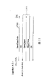
To be expression send to the figure of example of the script of DSC with ProcedureStart order to Figure 25 at first from printer.
Figure 26 be expression with ProcedureStart order then script 1 send to the figure of example of the script of printer from DSC.
Figure 27 is the figure of example 1 that sends to the script of printer when being illustrated in " basic process " with JobStart order from DSC.
Figure 28 is the figure of example 2 that sends to the script of printer when being illustrated in " basic process " with JobStart order from DSC;
Figure 29 is the figure that sends to the script of printer when being illustrated in " recommendation process " with the JobStart order from DSC.
Embodiment
Describe the preferred embodiments of the present invention with reference to the accompanying drawings in detail.
Fig. 1 is the general survey oblique view of the electrooptical direct printing machine (below be called the PD print apparatus) 1000 of embodiments of the invention.This PD print apparatus 1000 has from master computer (PC) and receives data and the function of the PC printer that the conduct that prints is common and directly read in the view data of being stored in the storage medium such as storage card and print or receive from the view data of digital camera and the function that prints.
In Fig. 1, the main body of the shell of the PD print apparatus 1000 of formation present embodiment has the external parts of housing M1001, last shell 1002, inlet cover 1003 and row's paper disc 1004.Lower casing 1001 forms the roughly Lower Half of PD print apparatus 1000, last shell 1002 forms the roughly first half of PD print apparatus 1000, be combined to form by two shells and have the hollow body structures of holding the spatial accommodation of each mechanism described later in inside, respectively form peristome on the facial and front face thereon.In addition, row's paper disc 1004 one ends remain on the lower casing 1001 with rotating freely, and can make peristome folding on the front face that is formed on lower casing 1001 by this rotation.Therefore, when operation of recording is carried out, to the front sideway swivel peristome is opened, just can be discharged record-paper (sheet) therefrom, can stack gradually the record-paper of being discharged simultaneously by the row's of making paper disc 1004.In addition, hold 2 auxiliary paper disc 1004a, 1004b row in advance in the paper disc 1004, and pull out each paper disc to the front as required, just can use 3 grades of ground of bearing area of paper to enlarge thus and dwindle.
On last shell 1002, be provided with power key 1005.Be provided with liquid crystal display part 1006 on the right side of last shell 1002 and have the guidance panel 1010 of key switch etc.The structure of this guidance panel 1010 is described in detail in the back with reference to Fig. 2.The 1007th, automatic paper feeding portion gives record-paper automatically in apparatus main body.The 1008th, paper is selector at interval, is the bar that is used to adjust the interval between printhead and the record-paper.The 1009th, card slot inserts the adapter that storage card can be installed here, and the view data that can directly be taken in storage card to be stored by this adapter also prints.As this storage card (PC), compact flash memory, intelligent medium, memory stick etc. are for example arranged.The 1011st, viewer (liquid crystal display part) can dismounting on the main body of this PD print apparatus 1000, under the situations such as image that retrieval is wanted to print from the image of being stored the PC card, is used to show the image of per 1 picture and thumbnail etc.The 1012nd, be used to connect the USB terminal of digital camera described later.The back of this PD print apparatus 1000 is provided with the USB connector that is used to connect personal computer (PC).
Fig. 2 is the overview of guidance panel 1010 of the PD print apparatus 1000 of present embodiment.
Among the figure, liquid crystal display part 1006 shows the menu item that is used to set various data relevant with the project of being printed about it.Project as shown here for example has: the initial photo sequence number of wanting the scope printed, assigned picture sequence number (appointment of starting image appointment/print screen), finished the last photo sequence number (end) of the scope printed, print umber (umber), usefulness paper (record-paper) kind of using in the printing (using the paper kind), 1 number with the photo of printing on the paper is set (layout), the quality of printing is specified (quality), whether print the appointment (date printing) on the date of being absorbed, whether proofread and correct the appointment (image rectification) that photo prints, print needed demonstration (using the paper number) etc. with the paper number.These projects use cursor keies 2001 are selected or are specified.The 2002nd, mode key whenever pressing this key with regard to changeable printing kind (index prints, all picture printings, 1 picture printing etc.), and is lighted the LED of the correspondence of LED2003 according to this.The 2004th, safeguard key, be the key that is used to print the Maintaining of Printer such as cleaning of head.The 2005th, the printing initiating key is pressed when the setting that beginning when or establish maintenance is printed in indication.The 2006th, print abort key and print when ending and indication is safeguarded when ending and is pressed making.
The formation of the major part that the control with PD print apparatus 1000 of present embodiment is relevant then is described with reference to Fig. 3.Wherein, in this Fig. 3, the part additional identical mark common with aforementioned figures, and omit its explanation.
Among Fig. 3,3000 expression control parts (control basal plate).3001 expression ASIC (dedicated custom LSI), its structure is described in detail in the back with reference to the block diagram of Fig. 4.The 3002nd, DSP (Digital Signal Processing processor), there is CPU inside, be responsible for various control and treatment described later and from luminance signal (RGB) to the image processing of the conversion of concentration signal (CMYK), scaling (scaling), gamma transformation, error diffusion etc. etc.The 3003rd, memory has the memory block of service area in the RAM district, storing image data etc. of the program storage 3003a of control program of CPU of storage DSP3002 and the program when carrying out as storage.The 3004th, Printer Engine, loads the Printer Engine of the ink-jet printer of the color inks printing color image that uses polychrome here.The 3005th, as the USB connector of the port that is used to connect digital camera (DSC) 3012.The 3006th, be used to connect the connector of viewer 1011.The 3008th, usb hub (USBHUB) when this PD print apparatus 1000 prints based on the view data from PC3010, makes from the data former state of PC3010 and passes through, and outputs to Printer Engine 3004 through USB3021.Thus, the PC3010 that is connected just can directly carry out the exchange of data, signal with Printer Engine 3004 and carry out and print (as general PC printer).The 3009th, power connector is imported from the next direct voltage of commercial AC conversion by power supply 3019.PC3010 is general personal computer, the 3011st, and above-mentioned storage card (PC card), the 3012nd, digital camera (DSC:DigitalStill Camera).
In addition, the handshaking between this control part 3000 and the Printer Engine 3004 is carried out through above-mentioned USB3021 or IEEE1284 bus 3022.
Fig. 4 is the block diagram of the structure of expression ASIC3001, in this Fig. 4, and the part also additional identical mark common with aforementioned figures, and omit its explanation.
The 4001st, PC clamping oral area reads in the view data of storage in the PC card of being installed 3011 or writes data etc. to PC card 3011, and the 4002nd, the IEEE1284 interface portion, and carry out exchanges data between the Printer Engine 3004.This IEEE1284 interface portion 4002 is employed buses when printing the view data of being stored in digital camera 3012 or the PC card 3011.The 4003rd, USB interface portion, and carry out exchanges data between the PC3010.The 4004th, USB main interface portion, and carry out exchanges data between the digital camera 3012.The 4005th, the guidance panel interface portion, input is from the various operation signals of guidance panel 1010, perhaps to display part 1006 output video datas etc.The 4006th, the viewer interface portion, control is to the demonstration of the view data of viewer 1011.The 4007th, control the interface portion of the interface between various switches and the LED4009 etc.The 4008th, cpu i/f portion, carry out and DSP3002 between the control of exchanges data.The 4010th, connect the internal bus (ASIC bus) of these each parts.
The following describes action summary based on above structure.
<common PC printer mode 〉
This is based on the printing model that the print data sent here from PC3010 is come print image.
In this pattern, when being transfused to, just directly deliver to Printer Engine 3004 through USB connector 1013 (Fig. 3), print based on data from PC3010 through usb hub 3008, USB3021 when data from PC3010.
<from the direct print mode of PC card 〉
Install or produce interruption when PC card 3011 on card slot 1009 when pulling down, thus, DSP3002 just can detect installation or pull down (taking off) PC card 3011.When PC card 3011 is installed, reads in compressed (for example JPEG compression) view data of storage in this PC card 3011 and be stored in the memory 3003.Then when using guidance panel 101 to indicate the printing of view data of these storages, by being contractd, the view data decompress(ion) that is compressed is stored in the memory 3003, execution, and outputs to Printer Engine 3004 through IEEE1284 interface portion 4002 and prints to the conversion of YMCK signal, γ correction, error diffusion etc. and be transformed into the record data that can be printed by Printer Engine 3004 from rgb signal.
<from the direct print mode of camera 〉
Fig. 5 is the PD print apparatus 1000 of explanation present embodiment and the figure that is connected of digital camera 3012.
Among the figure, cable 5000 has the connector 5001 that is connected with the connector 1012 of PD print apparatus 1000, with the connector 5002 that is used for being connected with the connecting connector 5003 of digital camera 3012, digital camera 3012 constitutes and can export the view data that is kept in the internal storage through connecting connector 5003.Can adopt inside to have and have the various structures such as slot that are used to install dismountable memory as the structure of digital camera 3012 as the memory of storage device.Like this, by connecting PD print apparatus 1000 and digital cameras 3012, directly print view data from digital camera 3012 with regard to available PD print apparatus 1000 through cable shown in Figure 5 5000.
Here, as shown in Figure 5, when on PD print apparatus 1000, connecting digital camera 3012, on the display part 1006 of guidance panel 1010, only show the camera sign, it is invalid that the demonstration of guidance panel 1010 and operation become, and it is invalid also to become to the demonstration of viewer 1011.Therefore, later on because the key operation of numeric only camera 3012 and show effectively to the image of the display part (not shown) of digital camera 3012, so the user can use this digital camera 3012 to print appointment.
In the present embodiment, purpose provides the PD print apparatus that the digital camera that can connect a plurality of manufacturers prints, and the communication protocol when the PD print apparatus 1000 that connects present embodiment and digital camera are printed is described in detail.
In the present embodiment, propose to use general file, general format to carry out the Control on Communication between PD print apparatus 1000 and the digital camera 3012, do not rely on the NCDP (New Camera Direct Print) of interface.
Fig. 6 is the figure of an example of this NCDP structure of expression.
Among the figure, 600 expressions utilize the interface of USB, and 601 expressions utilize the interface of bluetooth (Bluetooth).The application layer of being packed into when the system that utilizes NCDP is constructed in 602 expressions.The 603rd, be used to carry out the layer of existing protocol and interface, BIP (Basic Image Profile), USB interface of PTP (Picture TransferProtocol), SCSI and bluetooth etc. are installed here.The prerequisite of the NCDP of present embodiment is that the framework of such protocol layer etc. has been installed, and installs as application thereon.Here, PD print apparatus 1000 is defined as USB master's device, and camera 3012 is defined as USB from device (slave), as shown in Figure 6, is respectively identical NCDP structure
Fig. 7 is the figure that explanation utilizes the flow process of PD print apparatus 1000 that the NCDP of present embodiment carries out and the communication process between the digital camera (DSC) 3012.
Here, as shown in Figure 5 when detecting when connecting PD print apparatus 1000 and DSC3012, but just communicate between these equipment by USB cable 5000.Thus, carrying out the application and the beginning of being installed on these equipment shifts to the process 701 of utilizing NCDP.The initial condition of 702 expression NCDP, judgement type each other could be carried out NCDP here, if possible, then transfers to the process 701 of utilizing NCDP.If be the situation that DSC3012 does not install NCDP here, then do not carry out the Control on Communication of utilizing NCDP.Like this after transferring to NCDP, shown in 703, like that, when the transmission that utilizes the view data of " basic process " from the DSC3012 indication/printing, transfer to from DSC3012 PD print apparatus 1000 transmitted image files and the simple and easy printing model that prints.Such shown in 704, when the transmission that utilizes the view data of " recommendation process " from DSC3012 indication/printing, then after carrying out various negotiation between DSC3012 and the PD print apparatus 1000 and determining its print conditions, transfer to from DSC3012 PD print apparatus 1000 transmitted image data and the more senior printing model that prints.705 when carrying out the indication of " expansion process " by DSC3012, sets senior composing functions such as carrying out for example DPOF, XHTML-print, SVG and by the pattern of the printing of each peculiar specification of distributors of company.In addition, about the detail specifications of this utilization " expansion process ", therefore the expansion description regulation by each company of manufacturer of DSC does not specify here.In addition, print, describe in the back to Figure 11 with reference to Fig. 9 about the image that utilizes these " basic processes " and " recommendation process " to carry out.
Fig. 8 is explanation figure for the order that prints defined in the NCDP of present embodiment.
Among Fig. 8, " associative mode " correspondence is indicated from DSC3012, above-mentioned " basic process ", " recommendation process " and " expansion process ".Because with respect in " recommendation process ", using whole orders, " basic process " is simple and easy printing model, so only can use to the transfer of NCDP and its end, to the transfer command of each pattern of " basic process ", " recommendation process " and " expansion process ", obtain view data and from the print command of camera 3012 from camera 3012.In addition, although in " expansion process ", be recited as and only can use moving and its end to NCDP, to " basic process ". the transfer command of each pattern of " recommendation process " and " expansion process " but self-evident also can be such as mentioned above, use other orders according to the specification of each company.For example, also can be in " expansion process ", also with " recommendation process " serviceability order similarly, in this performance content, use intrinsic distinctive parameter kind of distributors and the such form of parameter value.
Below, the image printing that utilizes above-mentioned " basic process ", " recommendation process " is described.
Fig. 9 is the figure that the communication process of the NCDP the when image that utilizes " basic process " is printed is described.Should " basic process " be from DSC3012 to PD print apparatus 1000, print command is not each time all had the simple and easy printing model that print conditions ground only transmitted and printed 1 image file.Thereby the print conditions of the color correction of image and data conversion etc. is just by 1000 decisions of PD print apparatus.Picture format as corresponding therewith for example, for the RGB image of VGA size (640 * 480 pixel), the jpeg image of VGA size (640 * 480 pixel), is about below the 1M byte as image file size.The picture format that DSC3012 supports with PD print apparatus 1000 sends.At this moment, error process not.
At first in 900,1000 couples of DSC3012 send the order (NCDPStart) that indication is shifted to NCDP from the PD print apparatus.Here, if DSC3012 installs NCDP, then return OK (901).In addition, about used the object lesson of the situation of PTP as the example of situation of the affirmation process of carrying out this NCDP, describe in detail in the back with reference to Figure 14.
When such affirmation was equipped with NCDP each other, 1000 couples of DSC3012 sent the order of shifting to the NCDP pattern (ProcedureStart) (902) from the PD print apparatus.In 903, when " basic process " of sending from DSC3012 as simple and easy printing model, transfer to the printing model of utilization " basic process " later on respect to this.At this moment, the operation in passing through DSC3012 when selecting to want the image of printing and indicating printing, indicates the order (JobStart) of printing beginning to send to PD print apparatus 1000 (904) from DSC3012.Thus, PD print apparatus 1000 becomes simple and easy printing model, and DSC3012 is sent order (GetImage) and asks jpeg image (905).Thus, from DSC3012 PD print apparatus 1000 is sent jpeg image (Image Data) (906), when the printing of indicated image finished, the order (JobEnd) of the end of expression print job sent to DSC3012 (907) from PD print apparatus 1000 to print processing in the beginning PD print apparatus 1000 like this.With respect to this, when returning affirmative acknowledgement (OK) from DSC3012 (908), then finish the print processing that " basic process " is somebody's turn to do in utilization.Because should " basic process
Merely to carry out the prerequisite that is exchanged for of image appointed information, so if decision prints by " basic process ", the exchange ground that then can not carry out performance information described later directly is made as printable state.But, also can be by DSC and PD print apparatus both sides' performance decision, whether by should " basic process " exchanging.
Obtain in printer support " basic process ", " recommendation process ", " expansion process " which although put down in writing DSC in the present embodiment, but be not limited to this method, also can adopt DSC to select the method for suitable process based on the Printer Information of the type name of printer and distributors's name etc.For example also can be, DSC keeps " supporting the type list of file names of the printer of recommendation process ", selects recommendation process when the type name of the printer that is connected is arranged in tabulation, selects basic process in the time of not in tabulation.
Record the example of printer distributors name and printer model name when Figure 25 represents the ProcedureStart order the script that DSC is sent from printer, Figure 26 represents to follow above-mentioned script is put down in writing DSC distributors's name and DSC type name the script that printer is sent from DSC example.
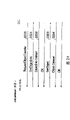
In the present embodiment, the only printing of specify image in advance of JobStart order in " basic process " has been described, picture format and file size are as situation about being determined regularly.Even this is also can not print because do not carry out the transmitting-receiving of performance information.But, even under the situation of the transmitting-receiving of not carrying out performance information, also can the specify image form and print conditions such as file size.For example also can with above-mentioned picture format etc. similarly, the projects of having approved between printer and DSC in advance about the situation of " printer side must be supported " or " printer side is suitably handled according to the performance of self " etc. are specified in the JobStart order by the DSC side.Because the structure that sampling is such, preferably by " NCDPStart " described later, only under the situation of exchange facility information each other for predetermined equipment, even if hand-off process is not so that there is performance information can specify print conditions in print job (script) yet, but, in order to prepare the operating process that is used on the beginner in advance, " basic process " that is used for saving the setting of trouble is important as far as possible.
The example that expression is not carried out any setting of relevant performance by the JobStart order when " basic process " among Figure 27 the script that printer is sent from DSC, when Figure 28 represents " basic process " at the example of setting from the script that DSC sends printer by the JobStart order about the project of the situation of between printer and DSC, approving " printer side must be supported " or " printer side is suitably handled according to the performance of self " in advance.
Figure 10 is the figure that the communication process of the NCDP when utilizing " recommendation process " to carry out the image printing is described, to the process additional identical sequence number common with top Fig. 9, and omits its explanation.By this " recommendation process ", can set with the negotiation between DSC3012 and the PD print apparatus 1000 is " more senior printing " pattern of prerequisite, can carry out many photo printing by once printing indication.And then, owing to use script (text) from the information of DSC3012, so can reflect the printing of many print conditions of color settings and Typeset and Print etc. to PD print apparatus 1000 transmission print conditions.But also error process.
Among Figure 10, same with the situation of Fig. 9, after having confirmed each other NCDP to be installed, at this moment, from indication " recommendation process " (910).Afterwards, carry out the process of being somebody's turn to do " recommendation process " of utilizing.At first shown in 911, function that PD print apparatus 1000 has this machine and the function that comprises with paper setting etc. all pass to DSC3012 as performance information.This performance information sends to DSC3012 with form of scripts (text).
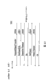
An example of this performance information of expression among Figure 12.
As shown in Figure 12, this performance information comprises and printable has or not and then also comprise as option the information that has or not the function corresponding with the manufacturing specification of each manufacturer etc. with the having or not of having or not of printing of paper kind and size, print quality, the form of view data, date, filename printing, layout, image rectification.
Like this,, just make transplanting simplification, make the easier standardization of exchange of this function information to the framework of other communication protocols by performance information being made as the script statement.In addition, this script statement also can be followed XML.
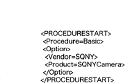
The user who receives the DSC3012 of this performance information judges which interior function of function of using this PD print apparatus 1000 to have prints, the image printed is wanted in selection, selects and determine the print conditions of this image simultaneously from the function that this PD print apparatus 1000 has.When such decision wanted that beginning is printed in the image printed and print conditions etc. and indication: print command (JobStart) just was sent to PD print apparatus 1000.The example of this JobStart is represented in Figure 29.Thus, from PD print apparatus 1000 send the request this view data order (
(912) it is replied the back and corresponding view data (ImageData) is sent (913) with PD print apparatus 1000 receivable picture formats (Tiff, JPEG, RGB etc.) from DSC3012.Here, making to print 1 image to send a plurality of view data, is because when specifying the Typeset and Print of 2 * 2 grades for example, need be to 1 view data that sends 4 tensors with paper.Like this, when indicated image was printed end, the order (JobEnd) that the expression print job finishes sent to DSC3012 (907) from PD print apparatus 1000., when returning affirmative acknowledgement (OK) from DSC3012 (908), transfer to the selective printing of the next image that utilization should " recommendation process " carries out once more and handle with respect to this.
Although in the present embodiment, even without the request from DSC3012, printer also sends performance information and sends to DSC, but be not limited to this form, also can be from the DSC side to the printer request performance, reply printer is sent to form from performance to the DSC side as it.Treating with such viewpoint under the situation of present embodiment, then:
Owing to ordering, the ProcedureStart that sends to " to the transfer of recommendation process " according to receiving sends performance, so " ProcedureStart " order has the connotation identical with " capability request ".
Performance information is as being sent out for replying of " ProcedureStart " order of " capability request ".
Figure 11 is in the communication process of the NCDP of explanation when the image that utilizes above-mentioned " recommendation process " is printed, produced the figure of the print procedure when wrong in the PD print apparatus 1000, to the process additional same sequence number common, and omit its explanation with above-mentioned Figure 10.
In this example, during the print processing of expression " recommendation process " is carried out, in PD print apparatus 1000, produced the example under the situation of paper supply mistake.At this moment, in 914, send the state information (Status) of expression paper supply mistake from 1000 couples of DSC3012 of PD print apparatus.With respect to this, based on judgement by the user of DSC3012, to PD print apparatus 1000 send expression be continue (JobContinue) still termination (JobAbort) this print processing (JobAbort) order (915) thus, in the PD print apparatus 1000, under the situation of ending, then end this print processing, the end notification (JobEnd) of transmission print job is also ended to be printed on and is indicated under the situation about continuing, move to wait for the recovery of this paper supply mistake, continue print processing.
Then with reference to the above-mentioned processing procedure of the flowchart text of Figure 13.
Figure 13 is the flow chart of the processing procedure of key diagram 7.
At first in step S1, establish the communication (700) between digital camera (DSC) 3012 and the PD print apparatus 1000, in step S2, judge whether these equipment have installed NCDP, if mounted words are then transferred to NCDP.Then enter step S3, receive process indication, and transfer to the process of this indication from DSC3012.Here, when indication " basic process ", enter step S5, carry out the print processing of utilizing " basic process " from step S4.When indication " recommendation process ", enter step S7 from step S6, carry out the print processing of utilizing above-mentioned " recommendation process ".And then, when indication " expansion process ", enter step S9 from step S8, carry out the print processing of " expansion process " that utilize corresponding each distributors.Under the situation beyond this, enter step S10, carry out the printing of the unique pattern that utilizes this PD print apparatus 1000 and DSC3012.
Although in Figure 13 of present embodiment, recorded and narrated the form that shifts to " basic process ", " recommendation process ", " expansion process ", " unique pattern " from the NCDP pattern, but in addition, also can be in the NCDP mode shifts, to become " basic process " selection mode, after become the state of accepting JobStart at once, afterwards, according to from the request of DSC or printer form to other processes, mode shifts.
Under situation about constituting like this, just can make that to transfer to printable state preferential.Just, for the beginner who does not understand setting hard to understand, just can respond that not hope is carried out the setting of trouble and the request that prints fast.On the other hand,, then can carry out the handover operation of process etc., carry out the setting of more detailed print conditions if can understand the skilled person of the switching of above-mentioned process.So just can design the system of the grasp level that meets the user.
Then explanation uses general PTP to realize the example (utilizing the packing (wrapper) of PTP) of the various command (Fig. 8) among the above-mentioned NCDP.In addition, although in the present embodiment, describe with the situation of the NCDP that used PTP, the present invention is not limited to this, for example also can go up in other classes of other interfaces (Class) direct print service API is installed.
[NCDPStart]
Figure 14 is that explanation uses the PTP framework to realize the figure of example of order (NCDPStart) of the beginning of indication NCDP process
With after DSC3012 physically is connected, at first in 1400,1000 couples of DSC3012 send GetDeviceInfo from the PD print apparatus at PD print apparatus 1000, to the DSC3012 request information relevant with the object of its maintenance.Send to PD print apparatus 1000 with respect to this DSC3012 by the relevant information of object that keeps among DeviceInfo Dataset handle and the DSC3012.Then in 1402,, DSC3012 is distributed, as required the data object distributed handle (handle) as resource, or send the request that begins that is used to carry out special initialized process by OpenSession.When returning affirmative acknowledgement (OK) from DSC3012, just begin to utilize the communication of PTP with respect to this.Then in 1403, DSC3012 is sent GetObjectHandles, when all handles (storage ID:FFFFFF, the object type: in the time of script) of request form of scripts, in 1404, return all handle list (ObjectHandleArray) that keep among the DSC3012 with respect to this.Then in 1405,1406, obtain the information of i object handle from PD print apparatus 1000.Here, when the keyword that in this object, includes the identification of representing DSC3012 (for example password " mountain "), then in 1407, transmission (SendObjectInfo) from 1000 pairs of DSC3012 denoted objects of PD print apparatus information, when this is received affirmative acknowledgement (OK), send object information from 1000 couples of DSC3012 of PD print apparatus by SendObject.Here, in this object, for example include " river " as the keyword (password) of replying for above-mentioned keyword.
Like this, the both sides of PD print apparatus 1000 and DSC3012 just can be familiar with each other and are connected the other side, just can be transferred to the process of utilizing NCDP (Fig. 7 701) afterwards.Like this, if can carry out the transport layer of file transfers, just can carry out the transmission of keyword reliably.That is, can in the NCDP of present embodiment, not append unique order etc., and use the PTP framework to exchange keyword.In addition,, as keyword, be not limited to above-mentioned example here, DSC3012 also can use identical keyword with PD print apparatus 1000.In order to shorten the time of utilizing this keyword to hold consultation, write this keyword in advance by foremost at the handle of form of scripts, just can shorten the required time of affirmation equipment each other.
[ProcedureStart]
Figure 15 is that explanation receives from DSC3012's, indication uses the PTP framework to realize from the figure of 1000 couples of DSC3012 of PD print apparatus to the example of the order (ProcedureStart) (902) of its mode shifts to the order of the transfer process of the printing model of NCDP.
Here at first in 1501, be process " basic process ", " recommendation process ", " expansion process " that DSC3012 notice PD print apparatus 1000 is supported, transmit by SendObjectInfo and want object information that DSC3012 is sent.When to this when DSC3012 sends affirmative acknowledgement (OK) here, in 1502, DSC3012 is transmitted the order that will send object by SendObject, send the relevant information of process with these PD print apparatus 1000 supports by 1503 the ObjectData that follows.Follow in 1504, PD print apparatus 1000 is transmitted the order (RequestObjectTransfer) of wanting to start GetObject action (transferring to propelling (push) pattern) from DSC3012.In 1505, when transmitting the order of the reception information relevant from PD print apparatus 1000 (GetObjectInfo), in 1506, this information is returned PD print apparatus 1000 thus by ObjectInfo Dataset with object information.Then in 1507 when when PD print apparatus 1000 is specified these object information and q request object information itself, by the process (" substantially ", " recommendation ", " expansion " etc.) (1508) of Object Dataset to the 1000 notice DSC3012 uses of PD print apparatus.
Thus, can be from the printing model of DSC3012 to PD print apparatus 1000 specify images.
[NCDPEnd]
Figure 16 is that explanation uses the PTP framework to be implemented in the figure of example of the order (NCDPEnd) of the end communication control process among the NCDP of present embodiment.
In this process, in 1600, transmit to have from the 1000 couples of DSC3012 of PD print apparatus and want the object information (SendObjectInfo) that sends, DSC3012 is sent the transmission of object information by SendObject, then the DSC3012 notice is withdrawed from from the MCDP pattern when this is received affirmative acknowledgement (OK) by ObjectData, in 1601, send CloseSession, make this sign off.Thus, finish to utilize the communication process of NCDP.
[Capability]
Figure 17 is that explanation uses the PTP framework to realize the figure to the example of the communication process of the performance order (Capability) of the function of DSC3012 notice PD print apparatus of the NCDP of present embodiment.
In this process, in 1700, transmit to have from the 1000 couples of DSC3012 of PD print apparatus by SendObjectInfo and want the object information that sends.And, in 1701,, then with form of scripts (Figure 12) DSC3012 is sent the function that PD print apparatus 1000 has by ObjectData by the transmission of SendObject to DSC3012 transmission object information.
[GetImage]
Figure 18 is that explanation uses the PTP framework to realize the figure of the example of view data (jpeg image) communication process (GetImage) that the PD print apparatus 1000 of the NCDP of present embodiment is obtained among the DSC3012 to be kept.
At first, in 1800, when from the relevant information of the object of 1000 requests of PD print apparatus and DSC3012 maintenance, information (ObjectInfoDataset) relevant with this object in 1801 sends to PD print apparatus 1000 from DSC3012.Then in 1802 when specifying this object and sending the request of obtaining (GetObject), in 1803 the image file of this request (ObjectDataset) from DSC3012 to 1000 transmissions of PD print apparatus.Like this, PD print apparatus 1000 just can be obtained desirable image file from DSC3012.
[StatusSend]
Figure 19 is that explanation uses the PTP framework to realize the figure from the example of the communication process of (StatusSend) such as 1000 pairs of DSC3012 notification errors of PD print apparatus states of the NCDP of present embodiment.
At first in 1900, have from 1000 pairs of DSC3012 notices of PD print apparatus by SendObjectlnfo and to want the object information that sends.DSC3012 is sent the ensemble of communication (ObjectInfoDataset) relevant with this object information in 1901 then, to affirmative acknowledgement (OK), send the state information of mistake in the PD print apparatus 1000 etc. by SendObject and ObjectDataset from DSC3012.Here, the data that send to DSC3012 from PD print apparatus 1000 are data (Script) of textual form.
[PageEnd]
Figure 20 be explanation use the PTP framework realize present embodiment NCDP notify the figure of the example of the communication process that 1 page print processing finishes (PageEnd) from 1000 couples of DSC3012 of PD print apparatus.
[JobEnd]
Figure 21 be explanation use the PTP framework realize present embodiment NCDP finish the figure of example of the communication process of (JobEnd) from the print job of 1000 pairs of DSC3012 notices of PD print apparatus.
Figure 20, in 21, after 1900 to 1901 processes of Figure 19 are carried out, Figure 20 1910 in, 1000 couples of DSC3012 notify 1 page print processing to finish from the PD print apparatus.Figure 21 1911 in finish from the print job of the 1000 couples of DSC3012 of PD print apparatus notice.Here, the data (EOP, task termination) that send to DSC3012 from PD print apparatus 1000 are the data (Script) of textual form.
[JobStart]
Figure 22 is that explanation uses the PTP framework to realize that the NCDP of present embodiment is from the figure of DSC3012 to the example of the communication process of (JobStart) of the 1000 notice print jobs of PD print apparatus.
At first in 2200, PD print apparatus 1000 is sent RequestObjectTransfer, impel PD print apparatus 1000 to send the GetObject order from DSC3012.Thus in 2201, when when PD print apparatus 1000 sends GetObjecInfo, DSC3012 sends the information relevant with the object information of wanting to send, when to this during from PD print apparatus 1000 request object information when (GetObject:2203), in 2204, send Object Dataset, PD print apparatus 1000 is sent print command from DSC3012.Here the data (printing initiation command) that send to PD print apparatus 1000 from DSC3012 are the data (Script) of textual form,
[JobAbort]
Figure 23 be explanation use the PTP framework realize present embodiment NCDP PD print apparatus 1000 is sent the figure of the example of the communication process of printing abort commands (JobAbort) from DSC3012.
[JobContinue]
Figure 24 be explanation use the PTP framework realize present embodiment NCDP PD print apparatus 1000 is sent the figure of the example of the communication process of printing again initiation command (JobContinue) from DSC3012.
Among Figure 23 and 24, after having carried out 2200 to 2203 the process of Figure 20, Figure 23 2301 in from DSC3012 PD print apparatus 1000 is sent the printing abort commands, Figure 24 2401 in, from DSC3012 PD print apparatus 1000 is sent and to print initiation command again.Here, sending to PD print apparatus 1000 data (print abort commands, print initiation command again) from DSC3012, is the data (Script) of textual form.
In addition, the present invention also goes for the system by a plurality of equipment (for example main frame, interface, reader, printer etc.) formation, also goes for the device (for example, photocopier, picture unit etc.) that is formed by individual equipment.
Need not superfluous words in addition, purpose of the present invention also can reach like this, the storage medium (perhaps recording medium) of the software program code by will having write down the function (the various print processing that the processing that the photograph pusher side carries out, printer side are carried out) that realizes above-mentioned form of implementation offers system or device exactly, and the program code that is kept in the storage medium is read and carried out to the computer of this system or device (perhaps CPU, MPU).In this case, just become the program code of reading from storage medium self will realize the function of above-mentioned form of implementation, the storage medium of storing this program code has just constituted the present invention.Need not superfluous words in addition, not only comprise the program code of reading by object computer, the situation that the function of above-mentioned form of implementation is achieved, also comprise indication according to this program code, Yun Zhuan operating system (OS) etc. is carried out part or all of actual treatment on computers, the situation that the function by this said form of implementation in processing front is achieved.
And then need not superfluous words, also comprise the program code of reading when from storage medium, be written to the function expansion card that inserts computer and/or be connected to after the memory that is possessed on the functional expansion unit of computer, according to the indication of this program code, the CPU that is possessed on this function expansion card and/or the functional expansion unit etc. carries out part or all situation about being achieved by the function of this said form of implementation in processing front of actual treatment.
As described above like that according to present embodiment, the PD print apparatus can be made as USB master's device, DSC is made as from device, before entering the printing action, the information that the performance that has with the PD print apparatus is relevant sends to DSC, at the DSC side group in the best printing model of this performance information decision and print.
In addition,, just carry out transplanting easily, standardization easily to other communication protocols by send this performance information with script.
In addition, the communication process of equipment room uses general format to carry out, and stipulates the communication process of the application of present embodiment thereon in the layer of position, just can stipulate not rely on the communication process of various interface specification thus.
In addition, in the print system of present embodiment, owing to connect not specific multiple arrangement, so these interfaces also are diversified.Therefore, need be by coming exchange message by the specification of various interface standard support.Thereby the function information that needs in the transmitting-receiving between these devices just is achieved by " file transmission " or " object transmission ", just can easily adapt to the various interface specification.
In addition, as the image supply arrangement, except that digital camera, can consider PDA, portable phone, TV, video equipment, image storage apparatus etc.
In addition, in general-purpose interface, except that above-mentioned USB, IEEE1394 etc., also comprise connection to networks such as internets.
The present invention is not limited to above-mentioned form of implementation, can carry out various changes and distortion without departing from the spirit and scope of the present invention.Therefore, in order to disclose scope of the present invention, additional following claim item.
Claims (18)
1. a print system makes image supply arrangement and printing device direct communication through communication interface, above-mentioned printing device is sent view data and prints from above-mentioned image supply arrangement, it is characterized in that:
Above-mentioned printing device has first printing model that sends the function information that comprises the print conditions that above-mentioned printing device can be handled and second printing model that does not send the function information of the print conditions that comprises that above-mentioned printing device can be handled,
In above-mentioned first printing model, above-mentioned printing device comprises the function information dispensing device, establish utilizing after the communicating by letter of the application of being installed on above-mentioned printing device and the above-mentioned image supply arrangement, above-mentioned image supply arrangement is sent above-mentioned functions information; Above-mentioned image supply arrangement comprises the print conditions dispensing device, sends the print conditions of setting based on by the function information that above-mentioned printing device sent to above-mentioned printing device;
In above-mentioned second printing model, above-mentioned printing device comprises print control unit, determines print conditions according to the print conditions that above-mentioned printing device can be handled, and according to above-mentioned determined print conditions print image data.
2. print system according to claim 1 is characterized in that:
In above-mentioned communication interface, above-mentioned printing device is set at main device, above-mentioned image supply arrangement is set at from device.
3. print system according to claim 1 is characterized in that: above-mentioned first printing model and second printing model are configured to replace according to the transmission about the type of above-mentioned image supply arrangement and above-mentioned printing device or supplier's information.
4. print system according to claim 1 is characterized in that:
Above-mentioned print conditions comprises the information with paper that above-mentioned printing device can be printed.
5. print system according to claim 1 is characterized in that:
According to from above-mentioned first printing model of the given settings of above-mentioned image supply arrangement or above-mentioned second printing model.
6. Method of printing, wherein image supply arrangement and printing device be through the communication interface direct communication, above-mentioned printing device is sent view data and prints from above-mentioned image supply arrangement, it is characterized in that, may further comprise the steps:
Communication steps establish to be utilized communicating by letter of the application of being installed on above-mentioned printing device and above-mentioned image supply arrangement;
Determining step, judgement are which of second printing model that sends first printing model of the function information comprise the print conditions that above-mentioned printing device can be handled or do not send the function information of the print conditions that comprises that above-mentioned printing device can be handled;
Print the control step; Control; So that when above-mentioned determining step is judged as first printing model after having established above-mentioned communication; Above-mentioned image-rendering device is sent the function information that comprises the print conditions that above-mentioned PRN device can be processed from above-mentioned PRN device; Above-mentioned image-rendering device is set print conditions based on the function information from above-mentioned PRN device; And above-mentioned PRN device is sent the print conditions of this setting; Above-mentioned PRN device is according to the print conditions print image data from above-mentioned image-rendering device
When above-mentioned determining step was judged as second printing model after having established above-mentioned communication, above-mentioned printing device was determined print conditions according to its print conditions that can handle and according to above-mentioned determined print conditions print image data.
7. Method of printing according to claim 6 is characterized in that:
In above-mentioned communication interface, above-mentioned printing device is set at main device, above-mentioned image supply arrangement is set at from device.
8. Method of printing according to claim 6 is characterized in that:
Above-mentioned first printing model and second printing model are configured to replace according to the transmission about the type of above-mentioned image supply arrangement and above-mentioned printing device or supplier's information.
9. Method of printing according to claim 6 is characterized in that:
Above-mentioned print conditions comprises the information with paper that above-mentioned printing device can be printed.
10. Method of printing according to claim 6 is characterized in that:
According to from above-mentioned first printing model of the given settings of above-mentioned image supply arrangement or above-mentioned second printing model.
11. a printing device through communication interface and the direct communication of image supply arrangement, and receives view data from above-mentioned image supply arrangement so that print above-mentioned view data, it is characterized in that:
Above-mentioned printing device has first printing model that sends the function information that comprises the print conditions that above-mentioned printing device can be handled and second printing model that does not send the function information of the print conditions that comprises that above-mentioned printing device can be handled,
In above-mentioned first printing model, above-mentioned printing device comprises
The function information dispensing device establish utilizing after the communicating by letter of the application of being installed on above-mentioned printing device and the above-mentioned image supply arrangement, sends above-mentioned functions information to above-mentioned image supply arrangement;
The print conditions receiving system receives by above-mentioned image supply arrangement based on the print conditions of being set by the function information that above-mentioned printing device sent from above-mentioned image supply arrangement; And
Printing equipment, according to the print conditions print image data that is received by described print conditions receiving system,
In second printing model, above-mentioned printing device comprises
Receiving system receives view data from above-mentioned image supply arrangement; And
Print control unit is determined print conditions and according to above-mentioned determined print conditions print image data according to its print conditions that can handle.
12. printing device according to claim 11 is characterized in that:
In above-mentioned communication interface, above-mentioned printing device is set at main device, above-mentioned image supply arrangement is set at from device.
13. printing device according to claim 11 is characterized in that:
Above-mentioned first printing model and second printing model are configured to and can replace according to the transmission about the type of above-mentioned image supply arrangement and above-mentioned printing device or supplier's information.
14. printing device according to claim 11 is characterized in that:
Establish with the communicating by letter of above-mentioned image supply arrangement after, above-mentioned second printing model of initial setting switches to above-mentioned first printing model from above-mentioned second printing model then.
15. printing device according to claim 11 is characterized in that:
Above-mentioned print conditions comprises the information with paper that above-mentioned printing device can be printed.
16. printing device according to claim 11 is characterized in that:
According to from above-mentioned first printing model of the given settings of above-mentioned image supply arrangement or above-mentioned second printing model.
17. the control method of a printing device, above-mentioned printing device be through communication interface and the direct communication of image supply arrangement, and receive view data from above-mentioned image supply arrangement so that print above-mentioned view data, it is characterized in that, may further comprise the steps:
Communication steps establish to be utilized communicating by letter of the application of being installed on above-mentioned printing device and above-mentioned image supply arrangement;
Determining step, judgement are which of second printing model that sends first printing model of the function information comprise the print conditions that above-mentioned printing device can be handled or do not send the function information of the print conditions that comprises that above-mentioned printing device can be handled;
Print the control step; Control above-mentioned PRN device; So that when above-mentioned determining step is judged as first printing model after having established above-mentioned communication; Above-mentioned image-rendering device is sent the function information that comprises the print conditions that above-mentioned PRN device can be processed from above-mentioned PRN device; Above-mentioned PRN device receives above-mentioned image-rendering device based on the print conditions of setting from the function information of above-mentioned PRN device from above-mentioned image-rendering device; And according to the print conditions print image data from above-mentioned image-rendering device
When above-mentioned determining step was judged as second printing model after having established above-mentioned communication, above-mentioned printing device was determined print conditions according to its print conditions that can handle, and according to above-mentioned determined print conditions print image data.
18. control method according to claim 17 is characterized in that:
Above-mentioned print conditions comprises the information with paper that above-mentioned printing device can be printed.
Applications Claiming Priority (4)
| Application Number | Priority Date | Filing Date | Title |
|---|---|---|---|
| JP2002163431 | 2002-06-04 | ||
| JP163431/2002 | 2002-06-04 | ||
| JP2003151231A JP4208640B2 (en) | 2002-06-04 | 2003-05-28 | Printing system, printing control method, printing apparatus, and control method therefor |
| JP151231/2003 | 2003-05-28 |
Related Parent Applications (1)
| Application Number | Title | Priority Date | Filing Date |
|---|---|---|---|
| CNB031386121A Division CN1272742C (en) | 2002-06-04 | 2003-06-03 | Printing system and control method thereof, and electrooptical direct printing apparatus |
Publications (2)
| Publication Number | Publication Date |
|---|---|
| CN1882027A CN1882027A (en) | 2006-12-20 |
| CN100493130C true CN100493130C (en) | 2009-05-27 |
Family
ID=30002209
Family Applications (2)
| Application Number | Title | Priority Date | Filing Date |
|---|---|---|---|
| CNB031386121A Expired - Fee Related CN1272742C (en) | 2002-06-04 | 2003-06-03 | Printing system and control method thereof, and electrooptical direct printing apparatus |
| CNB2006101002902A Expired - Fee Related CN100493130C (en) | 2002-06-04 | 2003-06-03 | Printing system, printing method, printing device and control method thereof |
Family Applications Before (1)
| Application Number | Title | Priority Date | Filing Date |
|---|---|---|---|
| CNB031386121A Expired - Fee Related CN1272742C (en) | 2002-06-04 | 2003-06-03 | Printing system and control method thereof, and electrooptical direct printing apparatus |
Country Status (4)
| Country | Link |
|---|---|
| US (4) | US8174711B2 (en) |
| JP (1) | JP4208640B2 (en) |
| KR (2) | KR100661483B1 (en) |
| CN (2) | CN1272742C (en) |
Families Citing this family (33)
| Publication number | Priority date | Publication date | Assignee | Title |
|---|---|---|---|---|
| JP4307015B2 (en) * | 2002-06-04 | 2009-08-05 | キヤノン株式会社 | Printing apparatus and control method thereof |
| US20050097263A1 (en) * | 2003-10-31 | 2005-05-05 | Henry Wurzburg | Flash-memory card-reader to IDE bridge |
| WO2005109172A1 (en) | 2004-05-12 | 2005-11-17 | Samsung Electronics Co., Ltd. | Method of providing multimedia data for direct printing, direct printing method and apparatus thereof |
| JP4533005B2 (en) * | 2004-06-08 | 2010-08-25 | キヤノン株式会社 | Printing apparatus and printer control method |
| KR100601690B1 (en) | 2004-07-06 | 2006-07-14 | 삼성전자주식회사 | System and method for wireless printing based on wireless LAN |
| JP4726239B2 (en) * | 2004-08-25 | 2011-07-20 | キヤノン株式会社 | Printing system, image supply device, printing apparatus and control method therefor |
| CN101006418A (en) * | 2004-08-27 | 2007-07-25 | 京瓷株式会社 | Portable terminal apparatus, and printing system and method |
| KR100644665B1 (en) * | 2004-12-15 | 2006-11-10 | 삼성전자주식회사 | Method and apparatus of printing data stored external storage device |
| JP4657744B2 (en) | 2005-01-28 | 2011-03-23 | 株式会社リコー | Digital image printing system, printing apparatus, digital image printing system control method, printing apparatus control method, program, and recording medium |
| JP4657743B2 (en) | 2005-01-28 | 2011-03-23 | 株式会社リコー | Printing system, printing apparatus, printing system control method, printing apparatus control method, program, and computer-readable storage medium |
| JP2006205549A (en) * | 2005-01-28 | 2006-08-10 | Ricoh Co Ltd | Digital image printing system, printer, control method of digital image printing system, control method of printer, program of printer and storage medium |
| US20060203257A1 (en) | 2005-03-11 | 2006-09-14 | Microsoft Corporation | System and method for managing output path with context preservation |
| JP4560430B2 (en) | 2005-03-17 | 2010-10-13 | 株式会社リコー | Image forming apparatus, image printing system, program, and image composition output method |
| JP2007034391A (en) * | 2005-07-22 | 2007-02-08 | Oki Data Corp | Print system |
| JP2007152603A (en) | 2005-12-01 | 2007-06-21 | Funai Electric Co Ltd | Printer |
| KR100750157B1 (en) * | 2006-01-18 | 2007-08-21 | 삼성전자주식회사 | Image forming system and image forming method |
| JP2007221272A (en) * | 2006-02-14 | 2007-08-30 | Canon Inc | Imaging apparatus and method of controlling same |
| JP4908967B2 (en) * | 2006-08-10 | 2012-04-04 | キヤノン株式会社 | Image input device, image output device, and transfer method |
| JP2008087416A (en) | 2006-10-04 | 2008-04-17 | Ricoh Co Ltd | Image formation device, image supply device, image printing system, image printing method, image forming program and image feeding program |
| US20100030346A1 (en) * | 2007-02-02 | 2010-02-04 | Mitsuhiro Watanabe | Control system and control method for controlling controllable device such as peripheral device, and computer program for control |
| JP2008290426A (en) | 2007-05-28 | 2008-12-04 | Ricoh Co Ltd | Image forming system, external device, image forming method, and image forming program |
| JP5586932B2 (en) * | 2009-12-11 | 2014-09-10 | キヤノン株式会社 | Data processing apparatus, image forming apparatus, data processing apparatus control method, image forming apparatus control method, and program |
| JP4971484B2 (en) * | 2010-05-24 | 2012-07-11 | 株式会社リコー | Image forming apparatus, image printing system, image supply apparatus, and image composition output method |
| CN102529423A (en) * | 2010-12-07 | 2012-07-04 | 研能科技股份有限公司 | Printing device |
| JP5800249B2 (en) * | 2013-06-21 | 2015-10-28 | カシオ計算機株式会社 | Imaging apparatus, photographing condition setting method, and program |
| JP6267030B2 (en) | 2014-03-26 | 2018-01-24 | キヤノンファインテックニスカ株式会社 | Recording apparatus and recording method |
| JP6494454B2 (en) | 2015-07-10 | 2019-04-03 | キヤノン株式会社 | Inkjet recording method and inkjet recording apparatus |
| US10471749B2 (en) | 2015-10-30 | 2019-11-12 | Hewlett-Packard Development Company, L.P. | Hinge set |
| CN107071764B (en) * | 2016-12-30 | 2019-12-31 | Oppo广东移动通信有限公司 | Direct connection communication control method and device and mobile terminal |
| JP7309427B2 (en) | 2019-04-15 | 2023-07-18 | キヤノン株式会社 | Inkjet recording device, recording method, and program |
| JP7301584B2 (en) | 2019-04-15 | 2023-07-03 | キヤノン株式会社 | Image processing device, image processing method, and program |
| JP7271282B2 (en) | 2019-04-15 | 2023-05-11 | キヤノン株式会社 | INKJET RECORDING DEVICE, CONTROL METHOD, AND PROGRAM |
| JP7334579B2 (en) * | 2019-10-31 | 2023-08-29 | ブラザー工業株式会社 | image forming device |
Family Cites Families (89)
| Publication number | Priority date | Publication date | Assignee | Title |
|---|---|---|---|---|
| US4433925A (en) * | 1981-11-10 | 1984-02-28 | Epson Corporation | Manually-operated dot printer for pocket sized calculators |
| JPH0423096A (en) | 1990-05-17 | 1992-01-27 | Fujitsu Ltd | Cash register |
| EP0650125A1 (en) * | 1993-10-20 | 1995-04-26 | Nippon Lsi Card Co., Ltd. | Handy computer with built-in digital camera and spot state recording method using the same |
| JPH07288621A (en) | 1994-04-20 | 1995-10-31 | Canon Inc | Server system |
| US6394571B1 (en) * | 1994-07-25 | 2002-05-28 | Canon Kabushiki Kaisha | Method and apparatus for controlling printing operation with externally supplied parameters |
| JPH09223096A (en) | 1996-02-20 | 1997-08-26 | Fuji Xerox Co Ltd | Manager and client device |
| JPH1067127A (en) * | 1996-04-23 | 1998-03-10 | Canon Inc | Ink jet recording device and image processing method |
| JPH09286125A (en) * | 1996-04-23 | 1997-11-04 | Canon Inc | Method for ink jet recording and apparatus therefor |
| JP3832089B2 (en) | 1997-05-26 | 2006-10-11 | セイコーエプソン株式会社 | Digital camera and printing system |
| US5793366A (en) * | 1996-11-12 | 1998-08-11 | Sony Corporation | Graphical display of an animated data stream between devices on a bus |
| WO1997050243A1 (en) | 1996-06-25 | 1997-12-31 | Casio Computer Co., Ltd. | Printing apparatus and printing system |
| JP3788643B2 (en) * | 1996-10-22 | 2006-06-21 | 富士写真フイルム株式会社 | Photo printing system |
| JP3625345B2 (en) | 1996-12-06 | 2005-03-02 | キヤノン株式会社 | Image processing system |
| US6115137A (en) * | 1996-12-06 | 2000-09-05 | Canon Kabushiki Kaisha | Image processing system, digital camera, and printing apparatus |
| JPH10200766A (en) | 1997-01-08 | 1998-07-31 | Seiko Epson Corp | Direct print adaptor |
| TW384611B (en) * | 1997-02-14 | 2000-03-11 | Canon Kk | Data communication apparatus and method |
| EP0859326A3 (en) * | 1997-02-14 | 1999-05-12 | Canon Kabushiki Kaisha | Data transmission apparatus, system and method, and image processing apparatus |
| US6298405B1 (en) * | 1997-02-14 | 2001-10-02 | Canon Kabushiki Kaisha | Data communication system, printing system and data communication apparatus |
| JP3774540B2 (en) * | 1997-04-10 | 2006-05-17 | キヤノン株式会社 | Data transfer method, image processing system and apparatus |
| JP3527380B2 (en) | 1997-02-26 | 2004-05-17 | 株式会社リコー | Service providing system, its server and printer |
| JPH10271370A (en) | 1997-03-25 | 1998-10-09 | Minolta Co Ltd | Electronic still camera |
| US20070013781A1 (en) * | 1997-03-25 | 2007-01-18 | Minolta Co., Ltd. | Digital camera with automatic operating mode selection |
| JP3622412B2 (en) * | 1997-03-25 | 2005-02-23 | セイコーエプソン株式会社 | Printing apparatus, printing method, and printing system |
| JPH10304187A (en) * | 1997-04-28 | 1998-11-13 | Canon Inc | Device and method for print control and storage medium |
| JP3711703B2 (en) | 1997-06-06 | 2005-11-02 | カシオ計算機株式会社 | COMMUNICATION SYSTEM, TRANSMISSION DEVICE, RECEPTION DEVICE, COMMUNICATION CONTROL METHOD OF THE SYSTEM, AND DATA TRANSMISSION METHOD |
| JPH1132295A (en) * | 1997-07-09 | 1999-02-02 | Olympus Optical Co Ltd | Digital color printer, digital camera and digital color print system using them |
| JPH1164961A (en) * | 1997-08-20 | 1999-03-05 | Sanyo Electric Co Ltd | Image printer |
| JP4054451B2 (en) * | 1997-08-26 | 2008-02-27 | キヤノン株式会社 | Communication device |
| JP3939825B2 (en) * | 1997-09-09 | 2007-07-04 | オリンパス株式会社 | Electronic camera |
| JPH11155118A (en) | 1997-11-20 | 1999-06-08 | Casio Comput Co Ltd | Electronic camera system |
| US6236486B1 (en) * | 1997-12-05 | 2001-05-22 | Intermec Ip Corp. | Data communication system for printer and handheld computer |
| JP4011701B2 (en) * | 1997-12-05 | 2007-11-21 | キヤノン株式会社 | Search apparatus and control method |
| JP3772517B2 (en) | 1998-02-26 | 2006-05-10 | ブラザー工業株式会社 | PRINT SYSTEM, PRINT METHOD, RECORDING MEDIUM CONTAINING PRINT PROCESSING PROGRAM, PRINT CONTROL DEVICE USED FOR PRINT SYSTEM, PRINT CONTROL METHOD, RECORDING MEDIUM RECORDED PRINT CONTROL PROGRAM |
| US6513073B1 (en) * | 1998-01-30 | 2003-01-28 | Brother Kogyo Kabushiki Kaisha | Data output method and apparatus having stored parameters |
| EP0981246A4 (en) * | 1998-03-16 | 2001-05-30 | Seiko Epson Corp | Photograph image printing system, photograph image printing machine, computer-readable storage medium stored with photograph image printing program |
| US7202962B2 (en) * | 1998-03-19 | 2007-04-10 | Oce-Technologies B.V. | Scan and print processing in a network system having a plurality of devices |
| US5967676A (en) * | 1998-03-31 | 1999-10-19 | Microtech Conversion Systems, Inc. | Image orientation system for disk printing |
| US6552743B1 (en) * | 1998-04-08 | 2003-04-22 | Hewlett Packard Development Company, L.P. | Digital camera-ready printer |
| US7107516B1 (en) * | 1998-04-13 | 2006-09-12 | Flashpoint Technology, Inc. | Method and system for viewing images from an image capture device on a host computer |
| US6912311B2 (en) * | 1998-06-30 | 2005-06-28 | Flashpoint Technology, Inc. | Creation and use of complex image templates |
| JP2000035864A (en) | 1998-07-16 | 2000-02-02 | Nec Yonezawa Ltd | Printing controller |
| JP2000118086A (en) | 1998-10-14 | 2000-04-25 | Fuji Photo Film Co Ltd | Printing system and printing designating processing method |
| US6535298B2 (en) * | 1998-10-15 | 2003-03-18 | Hewlett-Packard Company | Storing and retrieving digital camera images via a user-completed proof sheet |
| TW502172B (en) * | 1998-10-26 | 2002-09-11 | Winbond Electronics Corp | Digital camera to printer conversion device with USB structure |
| US6559971B1 (en) * | 1998-10-27 | 2003-05-06 | Hewlett-Packard Development Co., L.P. | Self-resizing demonstration page for a printing device |
| JP2000151883A (en) | 1998-11-09 | 2000-05-30 | Canon Inc | Information processing unit, its system and its storage medium |
| JP3357004B2 (en) * | 1999-02-08 | 2002-12-16 | オリンパス光学工業株式会社 | Electronic camera |
| JP3357005B2 (en) * | 1999-02-08 | 2002-12-16 | オリンパス光学工業株式会社 | Electronic camera, image printing mechanism, and method of determining remaining power of image printing mechanism |
| JP3437485B2 (en) * | 1999-04-13 | 2003-08-18 | キヤノン株式会社 | Image printing apparatus, image processing method, and storage medium |
| JP2000318270A (en) * | 1999-05-11 | 2000-11-21 | Minolta Co Ltd | Imaging apparatus and imaging method |
| US6806978B1 (en) * | 1999-05-14 | 2004-10-19 | Konica Corporation | Image pick-up printing apparatus |
| US6967728B1 (en) * | 1999-07-23 | 2005-11-22 | Electronics For Imaging, Inc. | Reusable and transferable printer driver preference system |
| MXPA00008041A (en) * | 1999-08-19 | 2002-03-15 | Sony Corp | Device and method for image processing, device and method for printing, system and method for image printing, and recording medium. |
| EP1130895A1 (en) | 1999-09-14 | 2001-09-05 | Sony Corporation | Image printing system |
| JP2001092611A (en) * | 1999-09-17 | 2001-04-06 | Canon Inc | Data processor and picture recording device and method for controlling data processor and method for controlling picture recording device and storage medium |
| WO2001037101A1 (en) | 1999-11-18 | 2001-05-25 | Matsushita Electric Industrial Co., Ltd. | Network connection apparatus and network system using this |
| JP3389545B2 (en) * | 1999-12-27 | 2003-03-24 | シャープ株式会社 | Recording device, reproducing device, and recording / reproducing device connecting these devices |
| US6711637B2 (en) * | 2000-01-11 | 2004-03-23 | Canon Kabushiki Kaisha | Communication apparatus, image processing apparatus, communication system, communication method, image processing method and storage medium |
| US7327387B2 (en) * | 2000-02-21 | 2008-02-05 | Fujifilm Corporation | Image pick-up information transmitting system and remote control method for an information transmitting system |
| JP2001287414A (en) * | 2000-04-05 | 2001-10-16 | Sony Corp | Apparatus and method for converting data, apparatus and method for printing, apparatus and method for controlling printing, system and method for printing, and method for transmitting data |
| JP2001290612A (en) | 2000-04-07 | 2001-10-19 | Nec Corp | Print system |
| JP2001298694A (en) | 2000-04-13 | 2001-10-26 | Konica Corp | Image pickup device, image recording system, image recorder and output characteristic correcting method |
| US7191236B2 (en) | 2000-05-02 | 2007-03-13 | Canon Kabushiki Kaisha | Transparent telecommunications system and apparatus |
| US7034880B1 (en) * | 2000-05-11 | 2006-04-25 | Eastman Kodak Company | System and camera for transferring digital images to a service provider |
| US7038714B1 (en) * | 2000-05-16 | 2006-05-02 | Eastman Kodak Company | Printing system and method having a digital printer that uses a digital camera image display |
| US7414746B2 (en) * | 2000-05-23 | 2008-08-19 | Fujifilm Corporation | Image data communication method |
| US6982800B1 (en) | 2000-07-05 | 2006-01-03 | Lexmark International, Inc. | Apparatus and method for data management within a photoprinter |
| JP3703376B2 (en) | 2000-07-21 | 2005-10-05 | キヤノン株式会社 | Information processing apparatus, information processing method, storage medium storing print processing program, and printing system |
| JP2002036682A (en) * | 2000-07-24 | 2002-02-06 | Canon Inc | Image recorder, image input unit, data processor, image recording method, and recording medium |
| JP2002086853A (en) | 2000-09-11 | 2002-03-26 | Canon Inc | Information processor, system, control method therefor, peripheral device, and printer driver |
| JP2002091841A (en) | 2000-09-13 | 2002-03-29 | Sanyo Electric Co Ltd | Network system and equipment recognizing method |
| JP2002095071A (en) | 2000-09-13 | 2002-03-29 | Sanyo Electric Co Ltd | Network system and control method of apparatus |
| JP2002111947A (en) | 2000-09-27 | 2002-04-12 | Canon Inc | Image processor and its method |
| US6914698B1 (en) * | 2000-09-28 | 2005-07-05 | Hewlett-Packard Development Company, L.P. | Dynamic smart album page layouts in a direct connect printer |
| US7633523B2 (en) * | 2001-02-09 | 2009-12-15 | Olympus Corporation | Image capturing device using correction information for preventing at least a part of correction process from being performed when image data is corrected at an external device |
| JP2003036152A (en) * | 2001-05-17 | 2003-02-07 | Matsushita Electric Ind Co Ltd | Information printing system |
| US6922258B2 (en) * | 2001-05-30 | 2005-07-26 | Polaroid Corporation | Method and apparatus for printing remote images using a mobile device and printer |
| US7142318B2 (en) * | 2001-07-27 | 2006-11-28 | Hewlett-Packard Development Company, L.P. | Printing web page images via a marked proof sheet |
| WO2003021978A1 (en) | 2001-08-10 | 2003-03-13 | Strix Systems, Inc. | Virtual linking using a wireless device |
| JP3950704B2 (en) * | 2002-02-21 | 2007-08-01 | キヤノン株式会社 | Image processing apparatus, image processing method, print control apparatus, print control method, and program |
| JP2004013349A (en) | 2002-06-04 | 2004-01-15 | Canon Inc | Imaging device, recording system, and recording control method thereof |
| JP2004009390A (en) | 2002-06-04 | 2004-01-15 | Canon Inc | Printer, its control method, and printing system |
| JP4307015B2 (en) | 2002-06-04 | 2009-08-05 | キヤノン株式会社 | Printing apparatus and control method thereof |
| JP4027161B2 (en) | 2002-06-04 | 2007-12-26 | キヤノン株式会社 | Printer apparatus and control method thereof |
| JP2004082528A (en) * | 2002-08-27 | 2004-03-18 | Seiko Epson Corp | Printing system |
| US7014374B2 (en) * | 2002-09-25 | 2006-03-21 | Seiko Epson Corporation | Printing apparatus and printing method for performing pre-communication with an external device |
| US7199895B2 (en) | 2003-01-23 | 2007-04-03 | Hewlett-Packard Development Company, L.P. | Processing a printer control command |
| US20040167974A1 (en) | 2003-02-20 | 2004-08-26 | Jeremy Bunn | Exposing mobile-enterprise printers using a universal plug and play proxy |
| US9001806B2 (en) | 2012-03-06 | 2015-04-07 | Intel Corporation | Method and apparatus for managing a probe response related to wireless medium access control |
-
2003
- 2003-05-28 JP JP2003151231A patent/JP4208640B2/en not_active Expired - Fee Related
- 2003-06-02 US US10/449,084 patent/US8174711B2/en active Active
- 2003-06-03 CN CNB031386121A patent/CN1272742C/en not_active Expired - Fee Related
- 2003-06-03 CN CNB2006101002902A patent/CN100493130C/en not_active Expired - Fee Related
- 2003-06-04 KR KR1020030036087A patent/KR100661483B1/en active IP Right Grant
-
2006
- 2006-08-23 KR KR1020060079915A patent/KR100663209B1/en not_active IP Right Cessation
-
2011
- 2011-01-24 US US13/012,114 patent/US8203741B2/en not_active Expired - Fee Related
-
2012
- 2012-05-17 US US13/473,883 patent/US8395802B2/en not_active Expired - Lifetime
-
2013
- 2013-02-07 US US13/761,459 patent/US9389824B2/en not_active Expired - Lifetime
Also Published As
| Publication number | Publication date |
|---|---|
| US9389824B2 (en) | 2016-07-12 |
| US8395802B2 (en) | 2013-03-12 |
| US8203741B2 (en) | 2012-06-19 |
| US20040041865A1 (en) | 2004-03-04 |
| US20110122442A1 (en) | 2011-05-26 |
| CN1882027A (en) | 2006-12-20 |
| KR20030095263A (en) | 2003-12-18 |
| JP4208640B2 (en) | 2009-01-14 |
| KR100663209B1 (en) | 2007-01-03 |
| KR100661483B1 (en) | 2006-12-27 |
| US8174711B2 (en) | 2012-05-08 |
| KR20060099492A (en) | 2006-09-19 |
| US20120224215A1 (en) | 2012-09-06 |
| CN1272742C (en) | 2006-08-30 |
| CN1469305A (en) | 2004-01-21 |
| JP2004064740A (en) | 2004-02-26 |
| US20130148166A1 (en) | 2013-06-13 |
Similar Documents
| Publication | Publication Date | Title |
|---|---|---|
| CN100493130C (en) | Printing system, printing method, printing device and control method thereof | |
| CN1984220B (en) | Recording system and control method thereof | |
| CN1264117C (en) | Photography apparatus, printing system and its printing control method | |
| CN1236596C (en) | Digital camera and printer | |
| JP4027161B2 (en) | Printer apparatus and control method thereof | |
| JP2004129221A (en) | Digital camera and printer | |
| EP1530878B1 (en) | Digital camera and control method thereof, and printing system | |
| CN1522866B (en) | Recording system and its control method, printer and its control method, and image sensing apparatus and its control method | |
| CN100371956C (en) | Image input device and its UI control method, and image output device | |
| JP3919716B2 (en) | Recording apparatus, image supply system, and control method therefor | |
| KR100825930B1 (en) | Image supply apparatus and recording apparatus, recording system including these apparatuses, and communication control method thereof | |
| EP1377018A2 (en) | Printing system, control method therefor, and photo-direct printing apparatus | |
| CN1758718B (en) | Digital camera and printer | |
| JP2004066602A (en) | Recording system, its controlling method, and direct printer | |
| JP2006168079A (en) | Recording system and method for recording it, image feeding apparatus and method for controlling it, recording apparatus and method for controlling it, program, and storing medium | |
| JP4612907B2 (en) | Image supply apparatus and control method thereof | |
| JP4987104B2 (en) | Printing apparatus and control method thereof | |
| JP4366379B2 (en) | Image supply apparatus and control method thereof | |
| JP2004364304A (en) | Digital camera apparatus and its control method |
Legal Events
| Date | Code | Title | Description |
|---|---|---|---|
| C06 | Publication | ||
| PB01 | Publication | ||
| C10 | Entry into substantive examination | ||
| SE01 | Entry into force of request for substantive examination | ||
| C14 | Grant of patent or utility model | ||
| GR01 | Patent grant | ||
| CF01 | Termination of patent right due to non-payment of annual fee |
Granted publication date: 20090527 Termination date: 20180603 |
|
| CF01 | Termination of patent right due to non-payment of annual fee |