CN100484324C - Positioning technique - Google Patents
Positioning technique Download PDFInfo
- Publication number
- CN100484324C CN100484324C CNB038161117A CN03816111A CN100484324C CN 100484324 C CN100484324 C CN 100484324C CN B038161117 A CNB038161117 A CN B038161117A CN 03816111 A CN03816111 A CN 03816111A CN 100484324 C CN100484324 C CN 100484324C
- Authority
- CN
- China
- Prior art keywords
- node
- target device
- observed result
- camber line
- probability
- Prior art date
- Legal status (The legal status is an assumption and is not a legal conclusion. Google has not performed a legal analysis and makes no representation as to the accuracy of the status listed.)
- Expired - Fee Related
Links
Images


Classifications
-
- H—ELECTRICITY
- H04—ELECTRIC COMMUNICATION TECHNIQUE
- H04W—WIRELESS COMMUNICATION NETWORKS
- H04W64/00—Locating users or terminals or network equipment for network management purposes, e.g. mobility management
-
- G—PHYSICS
- G01—MEASURING; TESTING
- G01S—RADIO DIRECTION-FINDING; RADIO NAVIGATION; DETERMINING DISTANCE OR VELOCITY BY USE OF RADIO WAVES; LOCATING OR PRESENCE-DETECTING BY USE OF THE REFLECTION OR RERADIATION OF RADIO WAVES; ANALOGOUS ARRANGEMENTS USING OTHER WAVES
- G01S5/00—Position-fixing by co-ordinating two or more direction or position line determinations; Position-fixing by co-ordinating two or more distance determinations
- G01S5/02—Position-fixing by co-ordinating two or more direction or position line determinations; Position-fixing by co-ordinating two or more distance determinations using radio waves
- G01S5/0252—Radio frequency fingerprinting
- G01S5/02528—Simulating radio frequency fingerprints
Abstract
A target device's location in a radio network is estimated by maintaining a probabilistic model (PM) for several sam-ple points that indicate expected distributions of signal values at a given location. The target device observes sig-nal values (OS), wherein the sequence of observations and the respective locations constitute a Hidden Markov Model. A graph (G) models the topology of the positioning environment. The graph indicates several nodes which are permissible locations in the environment and several arcs which are permissible transitions between two nodes. The graph (G) is used to estimate the target device's location based on the probabilistic model (PM) and the sequence of observations (OS).
Description
Technical field
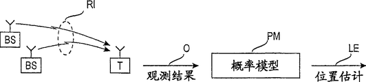
The present invention relates generally to location technology,, in the wireless communications environment of target device, come the position of estimating target equipment based on a series of observed results by described technology.Fig. 1 has roughly described the example of this class location technology.Described target device T communicates by base station BS by wave point RI.In described example, the communication of supposing is radio communication.Signal value on the described target device T observation wave point RI.Use observed result O in probabilistic model PM, described probabilistic model PM carries out modeling to the wireless communications environment of target device, and produces location estimation LE.As used herein, target device is that the position is with the equipment that is determined.Target device communicates by the signal in the wireless environment, and determines the position of target device with the signal value in the wireless environment.For example, target device may be the data processing equipment of communicating by letter in wireless lan (wlan).Described data processing equipment may be general-purpose laptop or palmtop computer or communication equipment, perhaps may be special test or the measurement mechanism that for example is connected to the medicine equipment of WLAN.Position as used herein is the coordinate set of one to three coordinate.For example under the particular case in tunnel, an independent coordinate is just enough at some, but the position is represented (x, y or angle/radius) by coordinate in most applications.
More particularly, the present invention relates to location technology based on hidden Markov model.Fig. 2 has roughly described hidden Markov model HMM.Model comprises transfer between position, the position and the observed result of being done on the position.In example shown in Figure 2, described target device along shown in 5 position q
T-2To q
T+2Path movement.More formally, q
tDefined the position distribution on time t, so P (q
t=s) be at the probability of the above target device of time t at position s.But,, will represent position distribution q with shorthand notation " position q " because position distribution can easily be converted into single location estimation.
Background technology
Position along the target device path can be called the path point.Described target device communicates by the signal in the wireless environment, and determines the position of described target device with the signal value in the wireless environment.
The practical example of described target device is the data processing equipment of communicating by letter in wireless lan (wlan) or cellular radio.Data processing equipment may be general-purpose laptop or palmtop computer or communication equipment, perhaps may be special test or the measurement mechanism that for example is connected to the medicine equipment of WLAN.Signal value as used herein is the measurable and amount that depends on the position of the signal of fixed launcher.For example, signal strength signal intensity and bit error rate/are measurable and depend on the example of the amount of position.
" hiding " etymology in the hidden Markov model is in such fact: we mainly pay close attention to q
T-2To q
T+2The position, but described position is not directly observable.Alternatively, we can be o based on signal value
T-2To o
T+2A series of observed result, but at observed result o
T-2... o
T+2With position q
T-2... q
T+2Between not simple relation.(position q is passed in attention
T-2To q
T+2Straight arrow be not to be intended to hint that described target device is to move along straight path or with constant speed, perhaps observed result is got in equal intervals.)
Notice that single " observed result " may comprise, and typically comprise really, measure from several signal values of one or more channels.In probabilistic model, idea is the probability distribution of measurement signal value, and if the signal value on the diverse location exist any overlappingly, then can not determine the position based on the single measurement of each position.Alternatively, in order to determine probability distribution, each observed result must comprise a plurality of measurements.
It is also understood that equally the time is quantized in Fig. 1 and 2.This means that the target device with a wireless receiver is put at any time only can observe a channel, but wireless receiver can in millisecond, be resetted to different channels, and typically with observed result o
T-2... o
T+2Separate at least one hundred milliseconds.Can select interval between the observed result based on the speed of typical target device.Therefore, even wireless receiver must be resetted at interchannel, single observed result also can comprise the signal value from several channels.
Wireless receiver can be measured for example signal value of signal strength signal intensity in fact continuously, but in the position application based on hidden Markov model, it is useful handling observed result with the time that is quantized.Therefore term " observed result " can be summarized as the statistic sampling of the several signal values in the preset time section.
A potential problem of the present invention comes from hidden Markov model: we can not observe the variable that monotonic relationshi is arranged with distance or position.Alternatively, described localization method is based on the observed result of signal value.Concerning two or more positions, have approximately equalised sets of signal values, and location estimation may be very inaccurate.
Summary of the invention
The device that the purpose of this invention is to provide method and the described method of realization is to alleviate above-mentioned shortcoming.In other words, the objective of the invention is to reduce the uncertainty of location technology, described location technology is based on the probabilistic model of expected signal value.Purpose of the present invention is reached by method and apparatus, and described method and apparatus is characterised in that what independent claims were stated.The preferred embodiments of the present invention are disclosed in the independent claims.
The present invention is based on the use of the topology of localizing environment being carried out the figure (or a picture group) of modeling.Figure G={V, A} comprises n node or summit V={v
1, v
2... v
nAnd m camber line A={a
1, a
2... a
m, so each camber line a
k=(v
i, v
j) described from v
iTo v
jPossible path or transfer.Can pass through the multiple combination of the camber line of figure G, describe all admissible routes in the localizing environment.For example, the figure G of typical office has the camber line at each corridor, connects the camber line (by door) in corridor to room or the like.Figure by several secondary interconnection or to describe the environment that comprises many floors with the secondary figure that some camber lines are described vertical transitions (elevator ﹠ stairs or escalator) be a problem whether, or significant.In computer-aided design, camber line signature song line segment, but in graph theory and context of the present invention, camber line is only represented two internodal connections.In the reality, camber line is painted as straight line.
Should be understood that, according to the figure of the present invention characteristic of described localizing environment normally, and be determined based on the obstacle in the localizing environment, compare with some location technologies of the prior art, the historical record of the self-position of described location technology based target equipment of the prior art and accessible speed come to determine respectively the admissible position of each target device.
An advantage of the invention is that the position that the quilt of described target device is reported moves naturally, moving of wall or other barrier can not appear passing in promptly described target device.Another advantage is that described figure is based on calibration measurement (calibration measurement) or calculates and to set up probabilistic model and taken on good basis.If the node of described figure also is used as the sample point of probabilistic model, then described navigation system can be the most accurately in the mobile zone at described target device.
If the position of described target device is interpreted as point or node among the figure, computer is moving of evaluating objects equipment more easily.In other words, being interpreted as a little in well-defined figure or position that the quilt of node is reported, comparing without any the optional position that quantizes, is better resource for data mining operation (datamining operation).For example, the designer of department store wishes pattern or the correlation that prospecting for customers is moved.If the node locating of figure on some desk, will be very easy to find whether client stops and also pass through desk y at desk x.Do not have described figure and amount wherein, the designer must seek the coordinate near each desk the specific region.Each node of figure is an admissible position, but an admissible position must not be the node of figure.Should select internodal distance based on the expection solution.In other words, who has drawn described figure, just must answer following point: can at a distance of how far between position of being reported and actual position? the characteristic of typical target device is depended in answer.If the described target device entrained communication equipment that is the people, then several meters error is acceptable, because the people can be recognized in several meters distances easily.On the other hand, if described target device comprises medicine equipment etc., littler solution is used in expectation.In majority was used, solution (euclidean distance between node pair) was about one meter.Littler distance is that cost provides better solution to increase resource consumption.The resource that is consumed comprises calibration measurement, the memory and the computing capability (computation power) of storage probabilistic model.Open space can be taken as the grid of level and vertical camber line.Because the visibility of open space is good, can accept conventional more coarse solution.
Can be with the following hidden Markov model that is connected to of described figure G.Make that d is along the typical distance between the point of camber line.Described typical distance is identical with desired solution, for example 1 meter.Make S={s
1, s
2... s
kBe some set along camber line, so dot spacing is from being d.S can be used as the hidden state variable q of hidden Markov model
iCodomain.
Internodal one group of transition probability in conjunction with figure preferably uses figure G.Can define transition probability P (q
t| q
T-1), therefore only when target device can be finished described transfer in the time period between two observed results, from s
iTo s
jTransition probability, i.e. P (q
t=s
j| q
T-1=s
i) be non-zero.
But two selecting technologies that use transition probability are described.First technology only based on the speed of typical target device, between the observed result time period and the point between distance.Make d
MaxBe the ultimate range of advancing in the maximum time period of described typical target device between observed result.Any length surpasses d
MaxTransfer have zero or very near zero probability.For example, the translational speed of people in typical indoor environment can surpass 2m/s hardly.Therefore if the time between two observed results is 1s, any probability that surpasses the transfer of two meters length all is zero, and is perhaps at least very low.(nonzero probability means that for example, but people almost never run run and do not forbidden by strictness.)
Second technology that is used for transition probability is based on the notion of adjacent or the point that is close to.If can arrive another point through camber line A and other any point of not visiting S from a bit, two some s
iAnd s
jBe exactly consecutive points.Say it is succinct based on adjacent technology from " set of G mean camber line also is the set of admissible transfer " this meaning, it has simplified calculating.Small shortcoming is such fact, and the report of the position of the target device of fast moving exists and postpones.Suppose described target device fast but move to a node linearly, described node and previous three nodes of estimated position distance.Allow because have only to the transfer of consecutive points, thus location estimation must through all between between node and carry out, this causes the delay in three observed result cycles.
According to another preferred embodiment of the present invention,, at first give transition probability with a predetermined value based on the speed of distance between the node and typical target device.When using navigation system, compile the historical record that target device moves, and empirical the transition probability of adjusting.
Do more discussion under the title that the use of transition probability will be in the back " based on the technology of recurrence ".
Description of drawings
According to preferred embodiment with reference to the accompanying drawings, hereinafter will be described in more detail, wherein the present invention
Fig. 1 has roughly described location technology;
Fig. 2 has described hidden Markov model;
Fig. 3 has described according to figure of the present invention;
Fig. 4 shows position estimation module LEM, and it comes the position of estimating target equipment based on the signal value on the wave point RI.
Fig. 5 A and 5B are the block diagrams of describing the typical target device that will be determined the position.
Fig. 6 has described the processing of long distance.
Fig. 7 shows the optimization technique of preparing probabilistic model based on figure according to the present invention.
How Fig. 8 will scheme to be used as route map if showing; And
Fig. 9 shows other example that Path selection was explained and optimized in the position.
Embodiment
Fig. 3 has described according to figure G of the present invention.In described example, described figure G comprises two subgraph G1 and G2, makes floor level Figure 31 of the corresponding one deck of subgraph G1, and floor level Figure 32 of corresponding two layers of subgraph G2.Described figure comprises the node that is plotted as black circle, so that each node is pointed out the admissible position of target device.Should select internodal distance based on desired solution.In majority was used, solution (internodal distance) was about one meter.Littler distance is that cost provides better solution to increase resource consumption.The resource that is consumed comprises calibration measurement, is used to store the memory and the computing capability of probabilistic model.For most offices, single node is just enough, for example at the node 311 in the room of upper left-hand.On the other hand, bigger room has more nodes, for example at the node 312 and 313 in the room of lower left-hand.Node 314 to 319 is the nodes that are positioned at open space.This category node should be placed like this: be issued to desired solution in the situation that does not consume too many computational resource.Described floor plan comprises the prohibited area 33 that with dashed lines draws.For example, described prohibited area can be that service desk, office equipment, building structure or target device can not move to any barrier wherein.Perhaps, in order to express more accurately, described target device can move in the zone 33, but its position is interpreted as the outside in zone 33.
Except node 310,311 of pointing out admissible position etc., described figure G comprises the camber line of pointing out admissible transfer between node.For the figure that keeps Fig. 3 is simple, only allow such camber line: camber line is a level or vertical and just in time connect two nodes without additional nodes.For example, camber line 331 connected nodes 314 and 315, and camber line 332 connected nodes 315 and 316, but there is not from node 314 to node 316 camber line.
Although the office space shown in Fig. 3 is three-dimensional, its two-dimensional space of being used as several interconnection is handled.Node 310 and 320 is respectively the entrance to one and two layer.Camber line 333 is connected to two floors with entrance 310,320.
Fig. 4 is the block diagram of exemplary position estimation module LEM, and described position estimation module is used for coming based on the signal value of wave point RI the position of estimating target equipment.Fig. 4 shows succinct position estimation module LEM, but may have how distributed embodiment equally.The essential characteristic of described position estimation module is the probabilistic model PM of the wireless environment of target device, given a plurality of observed results from wave point, and probabilistic model can be predicted the position of described target device.In described example, set up and safeguard probabilistic model PM by model construction module MCM.Model construction module MCM makes up based on calibration data CD (calibration data) or with the propagation data PD (propagation data) of one or more propagation model forms or any its and sets up and safeguard probabilistic model.Calibration data CD is at the result of the physical measurement signal value of known location (or determining the coordinate of described position, if described position is not known to other method).Alternatively, if signal parameter changes in time, described calibration data records also can comprise the time of measuring.Substitute described calibration data CD, perhaps except described calibration data, can use one or more propagation model PD to come wave point RI is carried out modeling.Can be by constructing propagation model with the ray tracing technology similar techniques that is used for vision simulation (visualsimulation).Concentrate the position of calibration measurement to be known as calibration point.Described calibration data CD comprises data record, and wherein each described record comprises the position of the calibration point of just discussing and the signal parameter set of measuring at described calibration point.Can be in any absolute or relative coordinate system the described position of expression.Under special situation such as for example train, highway, tunnel, water route etc., single coordinate is perhaps enough, but can use two or three co-ordinates usually.
Also have position computation module LCM, its observation set OS and probabilistic model PM that is used for based target equipment produces location estimation LE.For example, described position computation module can be realized by the software program of carrying out on kneetop computer or palmtop computer.Technical, ' measurement ' and ' observation ' can similarly be carried out, but for fear of obscuring, term " measurement " is often used as calibration measurement, and the signal parameter that obtains on the current location of described target device is known as " observed result ".The up-to-date observation set of described target device is known as current observed result.
Chart G has the several main application in the navigation system.For example, can between the tectonic epochs of probabilistic model, use described figure.The sample point of probabilistic model is preferably located on the node of described figure.For example, described model construction module MCM preferably includes automatic inspection, and in fact described automatic inspection has determined (calibration, emulation or interpolation) sample point at the node of each figure.
Described figure also is a good basis of determining the transition probability between possible position.
At last, described figure can be used for estimating or explaining the position of described target device.For example, the position of described target device can be interpreted as on the camber line point nearest from estimated position.Therefore described position is forced in the drawings the camber line.By described location solution being interpreted as the node from the nearest described figure in estimated position, described position can further be quantized.Can draw last position by the estimation that merges several centres explains.
Preferably use the part or all of application of described figure simultaneously, place the node of described figure and the position of estimating and explaining described target device based on described figure with sample point with probabilistic model.Because admissible position is positioned at or the node of approaching described figure, so position application is the most accurately near the node of described figure.On the contrary, in that for example the described position application of zone 33 disabled position may be mutually inaccurate, if but described zone can not enter at all, or the position message at least should the zone is the position of target device, and then any inaccurate in described zone all is unessential.Dotted line 41 and 42 has been described the use of figure G in model construction and location estimation/explanation respectively.Certainly, the importantly internal structure of described figure rather than its visual expression.
Fig. 5 A is a block diagram of describing the typical target device T that the position will be determined.In described example, described target device T is represented as the portable computer by wireless network RN communication.For example, described wireless network can be WLAN (WLAN (wireless local area network)) network.In the embodiment shown in Fig. 5 A, will not comprise that the position estimation module LEM of probabilistic model PM is installed among the described target device T.As a result, described target device T must pass through one or more connected base station BSs, and the observation set OS of described target device is sent to described position estimation module LEM.Described position estimation module LEM is back to described target device by wave point RI with the location estimation LE of described target device.
Fig. 5 B shows alternate embodiments, the described target device of wherein subsidiary computer PC is received in duplicating of probabilistic model PM on the detachable memory DM of CD-ROM disk (detachable memory) for example, and described target device T can determine the position of itself and need not send anything.As another selection (not illustrating individually), described subsidiary computer PC can connect by the internet of described position estimation module LEM and receives described probabilistic model (perhaps any other data).The broadband travelling carriage can receive described probabilistic model by described wave point RI.Also can use the mixing of described technology, so that receiver receives initial probabilistic model by wired connection or by detachable memory, and the renewal of described model is sent out by wave point subsequently.
Fig. 6 has described the processing of long distance.In described context, " length " means longer than the expection solution of described navigation system.If expectation has the rounding error (round-offerror) less than 1 meter, then any distance that surpasses two meters all is long.This long distance is usually in corridor and big open space.In described example, Figure 60 0 has two abiogenous nodes 601,605 at the corridor end, but one the way that the target device location solution is interpreted as in the endpoint node will be introduced too many quantization error.Therefore, preferably draw Figure 60 0 by computer aided program, make the operator only need to import the crooked and node 601 and 605 that is connected of natural occurring, and described automatic program identification surpass the distance of expection solution, and the node that adds of insertion on demand.For example, if from 601 to 605 distance is 9 meters, and allow 1 meter rounding error, by 3 additional nodes 602,603 and 604, the distance with 601 to 605 is divided into 4 sections camber lines 611 to 614 so.
Alternatively, if euclidean distance between node pair greater than described expection solution, we can carry out interpolation between node.For example, if the observed result of described target device corresponding to node 602 and 603, but node 602 more mates, and is inserted into the point 620 between 602 and 603 in then can the position with described target device.Yet, in many application, preferably enough thick and fast node is set, and the position of described target device is interpreted as the node nearest with the estimated position so that do not need interpolation.For example, come reduced data to excavate application by node rather than the point between the node that described estimated position is quantified as figure.
The node 601 to 605 of figure is the sample point of preferably described probabilistic model PM also.Exist and maybe may have several sample points.One type sample point is called calibration point, is based on the actual alignment of carrying out in the actual location environment and measures (seeing the calibration data among Fig. 4).The sample point of another kind of type is based on one or more propagation model PM and calculated.The 3rd type sample point is based on interpolation between calibration point or the calculated point.For example, suppose that node 601 and 605 is calibration points, node 602,603 and 604 can be derived from described calibration point by interpolation so.For following reason, described interpolation should be based on adding up on node 601 and 605 (on average) probability distribution.Suppose to use signal strength signal intensity to locate, and the signal strength signal intensity on node 601 have the probability peak of 20 unit.Probability peak is 40 unit on node 605.If average probability distribution, seemingly normal although the probability that is merged should have a peak value of 30 unit, the probability distribution that is merged still has the peak value of 20 and 40 unit.Therefore, the preferred form of interpolation be based on interpolation based on node on the merging of cumulative distribution function of signal value.If interpolation is not to occur in intermediate point, so known node is carried out distance weighted (distance-weighted) conversely.For example, suppose to come interpolation node 602 based on known calibration point 601 and 605, node 605 is 3 times of distances of node 601, therefore, the cumulative distribution function of node 601 is carried out the weighting stronger 3 times than the cumulative distribution function of node 605.
Fig. 7 shows the optimization technique of preparing probabilistic model based on figure according to the present invention.In step 71, be similar to computer-aided design (CAD) program display the floor plan of localizing environment.In step 72, the operator imports node coordinate and camber line.In step 73, the program of similar CAD detects the camber line that length surpasses the expection solution, and it is cut apart so that resulting camber line is shorter than described expection solution, as described in conjunction with Fig. 6 by inserting node.Described program may be inserted minimum extra node automatically, or the node with being inserted into of suitable quantity is prompted to the operator.In step 74, displayed map G, and most probable ground will be schemed G and be printed on the paper figure as calibration personnel.In step 75, calibrate described calibration node and/or calculating node based on propagation model.Come preferably to determine the node of operator's input by actual alignment or calculating.In optional step 76, based on node that be calibrated or calculated, determine the node that computer inserts by interpolation, described computer inserts and is undertaken by interpolation.In another optional step 77, as previously described, determine internodal transition probability based on the speed and the observed result frequency of typical target device.
How Fig. 8 will scheme to be used as route map if showing.Described route map can be used to refer to target device arrives expection by preferred path P position.For example, by minimize some for example the cost parameter in the path of length, time or energy (cost parameter of the path) optimize described path.As everyone knows, some path optimization's problems are very complicated, and can not reasonably solve in the time.The present invention itself does not relate to path optimization.Certainly, aspects more of the present invention relate to constitution optimization path from the camber line of figure G according to the present invention.Therefore, term " optimization " must not mean that described path is to optimize veritably, but the result of some optimizing processs (possible yes or no is best).
Can indicate to people or robot optimizing path P.Floor plan shown in Figure 3 and figure will be reused.For concrete example, suppose that environment is a hospital, carry target device the doctor of node (room) 312, and be in urgent need of doctors at node 325.Come the constitution optimization path P in order how to show from the camber line of described figure, Fig. 8 shows whole figure G, and it comprises subgraph G1 and G2 at every layer in two-layer.Yet, do not show that preferably whole figure G gives the doctor.Alternatively, optimization path P by node 312-319-310-320-324-321-325 only is shown.Because for example the typical target device of palmtop PC has small-sized display, so as the response of the detected position of described target device, preferably part display optimization path P and basic floor plan.At first, can show a part of 312-319-310 in the path on one deck, and the essential part of floor level Figure 31.When described target device during, show described part, and, show remainder 320-324-321-325 when described target device during near two layer 32 Ingress node 320 near stair or escalator 333.Therefore, not only the node of described figure is as the position that quantizes, and the selecteed camber line of described figure also can be by the compositional optimization path, and described path is from the detected position of described target device to the position of its expection.
Fig. 9 shows another example that Path selection was explained and optimized in the position.Suppose guard at node 910, and produced alarm in the somewhere of the another side of big obstacle 900.The target device that sends alarm is physically located in a little 920, and still far and away, described navigation system is not known definite position.The hypothetical probabilities navigation system is determined node (sample point) the 933rd, with the node of the nearest probability the highest (40%) of target device.In described example, described navigation system determines that node 931,932,933,934,935 and 936 has percent 5,5,40,35,10 and 5 probability respectively.In described example, if the location estimation of target device may be the probability distribution (or other probability surpasses the subclass of the node of given thresholding) of 931 to 936 6 nodes, but for most actual purposes, described probability distribution must be interpreted as single position.For example, the position of described target device can be interpreted as the probability weight merging (probability-weighted combination) of node 931 to 936.Described probability weight merging is shown as position 921.The location solution of described target device is interpreted as among the described figure G point or the node nearest with estimated position 921, usually is useful.Be point 922 with the nearest point in position 921 among the described figure G.
Sometimes, wish to explain or the position that quantizes described target device as one of the node of described figure (rather than arbitrfary point of described figure).Data mining and decision-making have been simplified in for example described quantification.Based on described probabilistic model, node 933 has as near the maximum probability of node.If the position of described target device is interpreted as node 933, to pass through node 932 from the optimization path of node 910.On the other hand, node 934 is to merge 921 node near the probability weight of node.If node 935 is passed through from the optimization path P of node 910 in the position of selecting node 934 to explain as the quilt of target device.Therefore, the preferred realization in described optimization path is the path that minimizes the desired value of some cost parameters, and described cost parameter is the length or the time in for example path.
In discussion up to now, only use the nearest observed result of described target device to estimate its position.Use description to the more advanced technology of location estimation below based on sequence (sequence-based).Technology based on recursion
The time series o of given observed result
1 T={ o
1..., o
T, we wish to determine t constantly, the position distribution q on 1≤t≤T
tSuppose observed result o
iOnly with current location q
iRelevant, and q
iOnly with last position q
I-1Relevant.The hypothesis of back means does not study the historical record that surpasses previous observed result.If satisfy described hypothesis, we can be expressed as orientation problem 1 rank hidden Markov model (HMM), wherein o
1 TBe observed result sequence and q
1 TIt is position sequence.Under described situation, o
1 TAnd q
1 TJoint probability be:
Therefore can determine described Joint Distribution fully according to following content:
1. initial condition probability P (q
1),
2. transition probability P (q
t/ q
T-1) and,
3. observed result probability P (o
t/ q
t).
If think that all positions have identical possibility, we can be by being provided with identical initial condition probability P (q for all positions
1) come formula of reduction 1.Therefore, Joint Distribution is only relevant with the observed result probability with transition probability.Can define described probability in many ways.For example, the space length of transition probability between can position-based is so that when described distance increased, described transition probability approached zero.Use described technology based on recursion owing to can determine transfer and observed result probability howsoever, from then on we supposed transition probability and observed result probability given.
The position distribution that can define on the moment t is:
P(q
t/o
1 T)=P(o
1 t,q
t)P(o
t+1 T/q
t)/P(o
1 T) [2]
Wherein from formula 3 and 4 (forward direction and reverse recursion), obtain P (o
1 t, q
t) and P (o
T+1 T/ q
t), and P (o
1 T) be to be used for normalized observed result probability.Make that S is the set of position possible in the described model and the size that n=|S| is S.The time complexity of forward direction and reverse recursion is O (T
m), wherein T is the length of historical record, and m is the quantity at the branch on non-zero probability of each moment step (time step).Significantly, because under worst case, all transfers all have nonzero probability, so m≤n
2Yet, because most of the transfer has zero probability, therefore in fact m<<n
2, this will make and calculate and can carry out soon.
P(o
1 t,q
t)=P(o
t/q
t)∑
qt-1P(q
t/q
t-1)P(o
1 t-1,q
t-1) [3]
P(o
t+1 T/q
t)=∑
qt+1P(o
t+1/q
t+1)P(q
t+1/q
t)P(o
t+2 T/q
t+1) [4]
Like this, we can obtain the probability at the diverse location of given time.Yet the location estimation of many application needs is single position rather than position distribution.In addition, exist multiple mode to calculate point estimation on the t constantly.For example, described point estimation can be the weighted average of position, and wherein location probability is used as weights, point estimation or can be the position with maximum probability.
In order to seek most probable route, can use the Viterbi algorithm.Described Viterbi algorithm can find to maximize probability P (o
1 T/ q
1=s
1..., q
T=s
T) position sequence s
1..., s
TSignificantly, can use location s
t, as the location estimation of moment t.Yet described method has such shortcoming: in each moment step, described location estimation only can be one of possible position.Therefore, the correctness of location estimation depends on the density of possible position.By using bigger S can improve correctness, described S has the very near possible position of phase mutual edge distance.Regrettably, this will fundamentally increase the time requirement of algorithm.
In order to obtain correct location estimation with rational amount of calculation, we can use relatively little S, and calculate the weighted average ∑ (w of the location estimation of moment t as possible position
i.s
i)/∑ w
iCan definition position s
iWeight w
iFor passing position s at moment t
iThe probability in most probable path.By using usually, and will end at s for each i=1...n at moment step 1-t (generation forward path) and the reverse viterbi algorithm of (generation reverse path) from moment step T to t
iForward direction and the probability multiplication of reverse path, obtain path probability.
Along with technical development, realize that in many ways notion of the present invention is tangible for a person skilled in the art.The present invention and embodiment are not limited to above-mentioned example, but can change within the scope of the claims.
Claims (19)
1. the method for the position of estimating target equipment (T) in wireless communications environment, described method comprises:
Maintenance is at the probability data model (PM) of a plurality of sample points, and each sample point comprises that sampling location on the described sample point and desired signal value distribute,
The observed result sequence (OS) of structure signal value, wherein each observed result is corresponding to the position separately along the path of target device, wherein said observed result sequence and the composition hidden Markov model of position separately,
It is characterized in that:
Form figure (G), described figure is used for the topology of described wireless communications environment is carried out modeling, and wherein said figure points out:
-node set (310-323; 601-605), each node is pointed out an admissible position in described wireless communications environment;
-camber line set (331-333; 611-614), each camber line is pointed out the transfer of admissible described target device between two nodes; And
Based on described probability data model (PM), described observed result sequence (OS) and described hidden Markov model, use described figure (G) to estimate the position of described target device.
2. according to the method for claim 1, it is characterized in that, use the step of described figure to comprise the position of estimating described target device, and the location solution of described target device is interpreted as on the camber line a bit (620,922) nearest from estimated position.
3. according to the method for claim 2, it is characterized in that, the location solution of described target device is interpreted as from the nearest node in estimated position (602).
4. according to the method for claim 1, it is characterized in that, use the step of described figure to comprise that the position of estimating described target device is as the point of described figure or the subclass of node, give each point in the described subclass or node with probable value, and described estimated position is interpreted as a little or the probability weight of the subclass of node merges.
5. according to the method for claim 1, it is characterized in that each camber line points out in time period between two observed results, the transfer of admissible described target device between two nodes.
6. according to the method for claim 1, it is characterized in that, use the sample point of described node as described probability data model (PM).
7. according to the method for claim 1, it is characterized in that the step that forms figure (G) comprises the following behavior of being carried out by programmed computer:
Receive node and coordinate camber line that point out from operations of operators person (72); And
Detect the camber line (600) that (73) length surpasses predetermined maximal distance, and cut apart described camber line by the node (602-604) that adds, described predetermined maximal distance is based on the speed of typical target device and the typical time period between the observed result.
8. according to the method for claim 7, it is characterized in that, the sample point of described probability data model (PM) is placed on the node of described figure (G), and:
-based on calibration and/or propagation model, on the node that the operator points out, determine at least some sample points; With
-carry out interpolation by the node of pointing out according to the operator, determine at least some sample points at additional node place.
9. according to any one method among the claim 1-8, it is characterized in that, determine the transition probability between (77) described node.
10. according to the method for claim 1, it is characterized in that described transition probability is based on the speed of typical target device and the typical time period between the observed result.
11. according to any one method among the claim 1-8, it is characterized in that, form optimization path (P) from the detected node (312) of described target device (T) to the node (325) of its expectation.
12. the method according to claim 10 is characterized in that, cooperates to come display optimization path (P) with basic figure or floor plan (31,32).
13. the method according to claim 11 is characterized in that, the response of the position that is detected as described target device partly shows described optimization path (P).
14. the method according to claim 12 is characterized in that, the response of the position that is detected as described target device partly shows described optimization path (P).
15. according to any one method among the claim 1-8, it is characterized in that, estimate the position of described target device based on the recursion of one or more described observed result sequences (OS).
16. the method according to claim 15 is characterized in that, described one or more recursion comprise forward recursion and reverse recursion.
17. the position estimation module (LEM) of estimating target equipment (T) position in wireless communications environment (RN), described position estimation module comprises:
At the probability data model (PM) of a plurality of sample points, each sample point comprises that the sample position of described sample point and expected signal value distribute,
The device of observed result sequence (OS) of structure signal value, wherein each observed result is corresponding to the position separately along the path of target device, wherein said observed result sequence and the formation hidden Markov model of position separately,
It is characterized in that:
Be used for the topology of wireless communications environment is carried out the figure (G) of modeling, wherein said figure points out:
-node set (310-323; 601-605), each node is pointed out an admissible position in described wireless communications environment;
-camber line set (331-333; 611-614), each camber line is pointed out the transfer of admissible target device between two nodes;
Be used for coming the device of the position of estimating target equipment based on described probability data model (PM), described observed result sequence (OS), described figure (G) and described hidden Markov model.
18. the position estimation module (LEM) according to claim 17 is characterized in that described position estimation module is included in the described target device (T).
19. the position estimation module (LEM) according to claim 17 is characterized in that described position estimation module is included in the standing part of described wireless communications environment (RN).
Applications Claiming Priority (2)
| Application Number | Priority Date | Filing Date | Title |
|---|---|---|---|
| FI20021357 | 2002-07-10 | ||
| FI20021357A FI114535B (en) | 2002-07-10 | 2002-07-10 | positioning Technology |
Publications (2)
| Publication Number | Publication Date |
|---|---|
| CN1666562A CN1666562A (en) | 2005-09-07 |
| CN100484324C true CN100484324C (en) | 2009-04-29 |
Family
ID=8564334
Family Applications (1)
| Application Number | Title | Priority Date | Filing Date |
|---|---|---|---|
| CNB038161117A Expired - Fee Related CN100484324C (en) | 2002-07-10 | 2003-07-08 | Positioning technique |
Country Status (8)
| Country | Link |
|---|---|
| US (1) | US7299059B2 (en) |
| EP (1) | EP1527649B1 (en) |
| JP (2) | JP4630660B2 (en) |
| CN (1) | CN100484324C (en) |
| AT (1) | ATE549893T1 (en) |
| AU (1) | AU2003244672A1 (en) |
| FI (1) | FI114535B (en) |
| WO (1) | WO2004008795A1 (en) |
Cited By (1)
| Publication number | Priority date | Publication date | Assignee | Title |
|---|---|---|---|---|
| CN104520844A (en) * | 2012-04-05 | 2015-04-15 | 爱立信(中国)通信有限公司 | Method and apparatus for determining geographic position of mobile terminals |
Families Citing this family (89)
| Publication number | Priority date | Publication date | Assignee | Title |
|---|---|---|---|---|
| US7257414B2 (en) | 1998-09-22 | 2007-08-14 | Polaris Wireless, Inc. | Estimating the Location of a Wireless Terminal Based on Non-Uniform Probabilities of Movement |
| US6393294B1 (en) | 1998-09-22 | 2002-05-21 | Polaris Wireless, Inc. | Location determination using RF fingerprinting |
| US7899467B2 (en) * | 1998-09-22 | 2011-03-01 | Polaris Wireless, Inc. | Estimating the location of a wireless terminal based on the traits of the multipath components of a signal |
| FI111901B (en) * | 2000-12-29 | 2003-09-30 | Ekahau Oy | Estimation of position in wireless communication networks |
| US8738024B1 (en) | 2008-03-29 | 2014-05-27 | Nexrf, Corp. | Delivering content within a boundary with beacons |
| US9373116B1 (en) | 2001-07-05 | 2016-06-21 | NexRf Corporation | Player tracking using a wireless device for a casino property |
| US10430492B1 (en) | 2006-11-30 | 2019-10-01 | Nexrf, Corp. | System and method for handset positioning with dynamically updated RF fingerprinting |
| US9396487B1 (en) | 2006-11-30 | 2016-07-19 | NexRf Corporation | System and method for weighting content items |
| US20020142844A1 (en) | 2001-02-06 | 2002-10-03 | Kerr Michael A. | Biometric broadband gaming system and method |
| US9507494B1 (en) | 2006-11-30 | 2016-11-29 | Nexrf, Corp. | Merchant controlled platform system and method |
| US9615347B1 (en) | 2006-11-30 | 2017-04-04 | NEXRF Corp. | Location positioning engine system and method |
| US9408032B1 (en) | 2006-11-30 | 2016-08-02 | NexRf Corporation | Content delivery system, device and method |
| US8942995B1 (en) | 2001-02-06 | 2015-01-27 | Nexrf, Corp. | Mobile autonomous dynamic graphical user interface |
| US9773020B2 (en) | 2001-07-05 | 2017-09-26 | NEXRF Corp. | System and method for map based exploration |
| US9349128B1 (en) | 2006-11-30 | 2016-05-24 | Nevrf Corporation | Targeted content delivery |
| FI113410B (en) * | 2002-05-31 | 2004-04-15 | Ekahau Oy | Probalistic model for positioning technique |
| US8156539B1 (en) * | 2002-12-18 | 2012-04-10 | Cypress Semiconductor Corporation | Method and system for protecting a wireless network |
| US7394372B2 (en) * | 2003-12-30 | 2008-07-01 | G2 Microsystems Pty. Ltd. | Method and apparatus for aggregating and communicating tracking information |
| US7212122B2 (en) * | 2003-12-30 | 2007-05-01 | G2 Microsystems Pty. Ltd. | Methods and apparatus of meshing and hierarchy establishment for tracking devices |
| FR2866774A1 (en) * | 2004-02-23 | 2005-08-26 | France Telecom | Terminal locating method for use in e.g. room of building, involves comparing radiation power received from terminals with power values stored in database, where values correspond to position of terminal with respect to terminals |
| FR2871893A1 (en) * | 2004-06-17 | 2005-12-23 | France Telecom | LOCATION OF MOBILE STATION IN A WIRELESS LOCAL NETWORK |
| US20060122944A1 (en) * | 2004-07-20 | 2006-06-08 | Ryan Philip J | Methods and systems for enabling communication to and from asset tracking devices |
| DE102004035531B4 (en) * | 2004-07-22 | 2006-10-26 | Fraunhofer-Gesellschaft zur Förderung der angewandten Forschung e.V. | Device and method for determining a current position of a mobile device |
| WO2006015265A2 (en) * | 2004-07-30 | 2006-02-09 | G2 Microsystems Pty Ltd. | Method and system for asset tracking devices |
| US7313421B2 (en) * | 2004-09-28 | 2007-12-25 | G2 Microsystems Pty. Ltd. | GPS receiver having RF front end power management and simultaneous baseband searching of frequency and code chip offset |
| US7403784B2 (en) | 2005-03-10 | 2008-07-22 | Avaya Technology Corp. | Method and apparatus for positioning a set of terminals in an indoor wireless environment |
| CN100456289C (en) * | 2005-10-25 | 2009-01-28 | 英业达股份有限公司 | Information collection system and method |
| US8000926B2 (en) * | 2005-11-28 | 2011-08-16 | Orthosensor | Method and system for positional measurement using ultrasonic sensing |
| US8265656B2 (en) | 2005-12-07 | 2012-09-11 | Ekahau Oy | Positioning technique |
| US7904097B2 (en) | 2005-12-07 | 2011-03-08 | Ekahau Oy | Location determination techniques |
| FI118787B (en) * | 2005-12-07 | 2008-03-14 | Ekahau Oy | Techniques for determining position |
| FI118715B (en) * | 2005-12-07 | 2008-02-15 | Ekahau Oy | position sensors |
| US7664511B2 (en) | 2005-12-12 | 2010-02-16 | Nokia Corporation | Mobile location method for WLAN-type systems |
| JP4445951B2 (en) | 2006-01-24 | 2010-04-07 | 株式会社エヌ・ティ・ティ・ドコモ | Area estimation system and area estimation method |
| US8758679B2 (en) * | 2006-03-31 | 2014-06-24 | The Invention Science Fund I, Llc | Surveying sterilizer methods and systems |
| US20070231192A1 (en) * | 2006-03-31 | 2007-10-04 | Searete Llc, A Limited Liability Corporation Of The State Of Delaware | Sterilization methods and systems |
| US8277724B2 (en) | 2006-03-31 | 2012-10-02 | The Invention Science Fund I, Llc | Sterilization methods and systems |
| US8932535B2 (en) | 2006-03-31 | 2015-01-13 | The Invention Science Fund I, Llc | Surveying sterilizer methods and systems |
| US8114342B2 (en) * | 2006-03-31 | 2012-02-14 | The Invention Science Fund I, Llc | Methods and systems for monitoring sterilization status |
| US11185604B2 (en) | 2006-03-31 | 2021-11-30 | Deep Science Llc | Methods and systems for monitoring sterilization status |
| US20070254015A1 (en) * | 2006-04-28 | 2007-11-01 | Searete Llc, A Limited Liability Corporation Of The State Of Delaware | Sanitizing surfaces |
| JP2007316068A (en) * | 2006-05-22 | 2007-12-06 | Polaris Wireless Inc | Method of estimating location of wireless terminal |
| JP2007316070A (en) | 2006-05-22 | 2007-12-06 | Polaris Wireless Inc | Method for predicting position of wireless terminal |
| US8023959B2 (en) * | 2006-06-28 | 2011-09-20 | Motorola Mobility, Inc. | Method and system for personal area networks |
| JP4848900B2 (en) * | 2006-09-05 | 2011-12-28 | 日本電気株式会社 | POSITION INFORMATION ESTIMATION DEVICE, POSITION INFORMATION ESTIMATION METHOD, AND POSITION INFORMATION ESTIMATION PROGRAM |
| DE102006061650A1 (en) * | 2006-09-20 | 2008-04-03 | Fraunhofer-Gesellschaft zur Förderung der angewandten Forschung e.V. | Concept for locating a position on a path |
| JP2010507985A (en) * | 2006-10-25 | 2010-03-11 | マサチューセッツ インスティテュート オブ テクノロジー | Coordinated location in wireless networks |
| US9406079B1 (en) | 2006-11-30 | 2016-08-02 | NexRf Corporation | Content relevance weighting system |
| US9043222B1 (en) | 2006-11-30 | 2015-05-26 | NexRf Corporation | User interface for geofence associated content |
| US9501786B1 (en) | 2006-11-30 | 2016-11-22 | Nexrf, Corp. | Interactive display system |
| CN101222753B (en) * | 2007-01-11 | 2010-12-08 | 财团法人工业技术研究院 | Novel sampling location determination method for objective device locating in wireless system |
| JP4616315B2 (en) | 2007-08-13 | 2011-01-19 | 株式会社エヌ・ティ・ティ・ドコモ | Area estimation system, area estimation method, and area estimation apparatus |
| US8600674B1 (en) * | 2007-08-15 | 2013-12-03 | University Of South Florida | Using pattern recognition in real-time LBS applications |
| JP2009159336A (en) * | 2007-12-26 | 2009-07-16 | Panasonic Corp | Behavior range grasping method and behavior grasping apparatus |
| US11729576B2 (en) | 2008-03-29 | 2023-08-15 | NEXRF Corp. | Targeted content delivery |
| US11706733B1 (en) | 2008-03-29 | 2023-07-18 | NEXRF Corp. | Location positioning engine system and method |
| JP5401651B2 (en) * | 2009-10-01 | 2014-01-29 | 株式会社国際電気通信基礎技術研究所 | Communications system |
| CN101795460B (en) * | 2009-12-23 | 2013-01-30 | 大连理工大学 | Markov mobility model suitable for mobile Ad Hoc network in obstacle environment |
| WO2011091549A1 (en) | 2010-01-27 | 2011-08-04 | Motorola Mobility, Inc. | Real-time location estimation of a mobile station in a wireless communication system |
| US8775065B2 (en) * | 2010-04-05 | 2014-07-08 | Qualcomm Incorporated | Radio model updating |
| US10721705B1 (en) | 2010-06-04 | 2020-07-21 | NEXRF Corp. | Content Relevance Weighting System |
| US8825388B2 (en) * | 2010-07-13 | 2014-09-02 | Qualcomm Incorporated | Indoor likelihood heatmap |
| JP5166502B2 (en) * | 2010-10-21 | 2013-03-21 | 株式会社日立製作所 | Positioning data management server and positioning data management method |
| US8981995B2 (en) | 2011-06-03 | 2015-03-17 | Microsoft Technology Licensing, Llc. | Low accuracy positional data by detecting improbable samples |
| US9470529B2 (en) | 2011-07-14 | 2016-10-18 | Microsoft Technology Licensing, Llc | Activating and deactivating sensors for dead reckoning |
| US9464903B2 (en) | 2011-07-14 | 2016-10-11 | Microsoft Technology Licensing, Llc | Crowd sourcing based on dead reckoning |
| KR101250495B1 (en) | 2011-11-25 | 2013-04-03 | 경기대학교 산학협력단 | Method and apparatus for estimating position of wifi devece |
| ITRM20110691A1 (en) * | 2011-12-29 | 2013-06-30 | Bruno Biscontini | PROCEDURE FOR LOCALIZING A TARGET IN A CLOSED ENVIRONMENT. |
| US9389302B2 (en) | 2012-07-18 | 2016-07-12 | Google Technology Holdings LLC | Real-time location estimation of a mobile station in a wireless communication system |
| US9817125B2 (en) | 2012-09-07 | 2017-11-14 | Microsoft Technology Licensing, Llc | Estimating and predicting structures proximate to a mobile device |
| CN103068041B (en) * | 2012-12-31 | 2015-12-23 | 广州杰赛科技股份有限公司 | A kind of localization method |
| US10152874B2 (en) | 2013-04-18 | 2018-12-11 | Airista Flow, Inc. | Processing alert signals from positioning devices |
| US9213474B2 (en) * | 2013-06-21 | 2015-12-15 | Baker Hughes Incorporated | System and method for displaying well data |
| GB2517691A (en) | 2013-08-26 | 2015-03-04 | Univ Dublin City | Location detection system and method |
| ES2727483T3 (en) * | 2013-12-19 | 2019-10-16 | Luxembourg Inst Science & Tech List | Method for determining indoor locations of mobile receiver units |
| JP6284151B2 (en) * | 2014-04-03 | 2018-02-28 | 日本電信電話株式会社 | Position estimation apparatus, method, and program |
| US10503912B1 (en) | 2014-08-12 | 2019-12-10 | NEXRF Corp. | Multi-channel communication of data files |
| WO2016098457A1 (en) * | 2014-12-17 | 2016-06-23 | ソニー株式会社 | Information processing device, information processing method, and program |
| US9788155B1 (en) | 2015-04-22 | 2017-10-10 | Michael A. Kerr | User interface for geofence associated content |
| JP6480297B2 (en) * | 2015-09-29 | 2019-03-06 | 株式会社Nttドコモ | Terminal device and positioning program |
| CN105448108B (en) * | 2015-12-30 | 2017-10-03 | 上海经达信息科技股份有限公司 | A kind of hypervelocity method of discrimination based on Hidden Markov road network |
| US10838582B2 (en) | 2016-06-15 | 2020-11-17 | NEXRF Corp. | Mobile autonomous dynamic graphical user interface |
| CN106443624B (en) * | 2016-09-14 | 2019-02-22 | 清华大学 | A kind of object detecting and tracking integral method |
| US10542386B2 (en) * | 2017-03-03 | 2020-01-21 | Here Global B.V. | Horizontal position estimate based on interfloor connectors |
| CN107466012B (en) * | 2017-08-24 | 2020-04-03 | 北京邮电大学 | Network switching optimization method based on mobility prediction under indoor home network |
| US11083419B2 (en) | 2017-10-13 | 2021-08-10 | J. Brasch Co., Llc | Assistive technology for operating nursing homes and other health care facilities |
| US10582332B2 (en) | 2017-12-11 | 2020-03-03 | Nokia Of America Corporation | Autonomous localization in wireless networks |
| KR102233885B1 (en) * | 2019-11-18 | 2021-03-30 | 울산과학기술원 | Method of determining a location where terminal has moved and terminal location determination device performing method |
| CN112434228B (en) * | 2020-11-27 | 2022-11-29 | 中国科学院电子学研究所苏州研究院 | Method for predicting track position of moving target |
Family Cites Families (15)
| Publication number | Priority date | Publication date | Assignee | Title |
|---|---|---|---|---|
| JPH0278907A (en) * | 1988-09-16 | 1990-03-19 | Hitachi Ltd | Navigation system using map data and location system for moving body |
| US5781150A (en) * | 1995-01-25 | 1998-07-14 | American Technology Corporation | GPS relative position detection system |
| JP3161334B2 (en) * | 1996-07-29 | 2001-04-25 | 松下電器産業株式会社 | Position detection device |
| FI105384B (en) | 1997-10-03 | 2000-07-31 | Nokia Networks Oy | A method for determining the location of a terminal and a cellular radio system |
| JP3299927B2 (en) * | 1998-01-29 | 2002-07-08 | 沖電気工業株式会社 | Mobile communication system and mobile station position estimation method |
| DE19936846A1 (en) * | 1998-08-06 | 2000-04-06 | Cell Loc Inc | Network-based wireless location method for cellular mobile telephones, involving calling cellular telephone, monitoring paging over control channel, and gathering and processing response via reverse control channel |
| US6269246B1 (en) | 1998-09-22 | 2001-07-31 | Ppm, Inc. | Location determination using RF fingerprinting |
| US6393294B1 (en) | 1998-09-22 | 2002-05-21 | Polaris Wireless, Inc. | Location determination using RF fingerprinting |
| US6944465B2 (en) * | 1998-09-22 | 2005-09-13 | Polaris Wireless, Inc. | Estimating the location of a mobile unit based on the elimination of improbable locations |
| KR100378124B1 (en) * | 1998-12-10 | 2003-06-19 | 삼성전자주식회사 | Device and method for estimating the position of terminal in mobile communication system |
| JP3607516B2 (en) * | 1999-01-20 | 2005-01-05 | 松下電器産業株式会社 | Mobile map matching device |
| US6263208B1 (en) * | 1999-05-28 | 2001-07-17 | Lucent Technologies Inc. | Geolocation estimation method for CDMA terminals based on pilot strength measurements |
| WO2001033825A1 (en) * | 1999-11-05 | 2001-05-10 | Signalsoft Corp. | Spatial toolkits for wireless location based services |
| DE10056222A1 (en) * | 2000-11-13 | 2002-05-23 | Siemens Ag | Traffic localization in cellular mobile radio network involves processing products of observation and transition probabilities for sequences of reports for all paths of same length |
| FI111901B (en) * | 2000-12-29 | 2003-09-30 | Ekahau Oy | Estimation of position in wireless communication networks |
-
2002
- 2002-07-10 FI FI20021357A patent/FI114535B/en not_active IP Right Cessation
-
2003
- 2003-07-08 WO PCT/FI2003/000553 patent/WO2004008795A1/en active Application Filing
- 2003-07-08 CN CNB038161117A patent/CN100484324C/en not_active Expired - Fee Related
- 2003-07-08 AU AU2003244672A patent/AU2003244672A1/en not_active Abandoned
- 2003-07-08 JP JP2004520698A patent/JP4630660B2/en not_active Expired - Lifetime
- 2003-07-08 AT AT03738151T patent/ATE549893T1/en active
- 2003-07-08 EP EP03738151A patent/EP1527649B1/en not_active Expired - Lifetime
-
2005
- 2005-01-07 US US11/030,334 patent/US7299059B2/en active Active
-
2008
- 2008-06-18 JP JP2008159562A patent/JP2009002949A/en active Pending
Non-Patent Citations (2)
| Title |
|---|
| Wireless Position Location:Fund Amentals, ImplementationStrategies, and Sources of Error. KRIZMAN K J ET.IEEE VEHICULAR TECHNOLOGY CONFERENCE,Vol.47 . 1997 |
| Wireless Position Location:Fund Amentals, ImplementationStrategies, and Sources of Error. KRIZMAN K J ET.IEEE VEHICULAR TECHNOLOGY CONFERENCE,Vol.47 . 1997 * |
Cited By (2)
| Publication number | Priority date | Publication date | Assignee | Title |
|---|---|---|---|---|
| CN104520844A (en) * | 2012-04-05 | 2015-04-15 | 爱立信(中国)通信有限公司 | Method and apparatus for determining geographic position of mobile terminals |
| CN104520844B (en) * | 2012-04-05 | 2018-05-08 | 爱立信(中国)通信有限公司 | Method and apparatus for the geo-location for determining mobile terminal |
Also Published As
| Publication number | Publication date |
|---|---|
| AU2003244672A1 (en) | 2004-02-02 |
| FI114535B (en) | 2004-10-29 |
| US20050197139A1 (en) | 2005-09-08 |
| JP2009002949A (en) | 2009-01-08 |
| WO2004008795A1 (en) | 2004-01-22 |
| CN1666562A (en) | 2005-09-07 |
| JP4630660B2 (en) | 2011-02-09 |
| EP1527649B1 (en) | 2012-03-14 |
| ATE549893T1 (en) | 2012-03-15 |
| US7299059B2 (en) | 2007-11-20 |
| JP2005532560A (en) | 2005-10-27 |
| FI20021357A0 (en) | 2002-07-10 |
| EP1527649A1 (en) | 2005-05-04 |
| FI20021357A (en) | 2004-01-11 |
Similar Documents
| Publication | Publication Date | Title |
|---|---|---|
| CN100484324C (en) | Positioning technique | |
| CA2638754C (en) | Position detection and location tracking in a wireless network | |
| US7196662B2 (en) | Probabilistic model for a positioning technique | |
| Jiang et al. | A practical and economical ultra-wideband base station placement approach for indoor autonomous driving systems | |
| US7349683B2 (en) | Sequence-based positioning technique | |
| KR100372497B1 (en) | Method and system for estimating a subscriber's location in a wireless communication system service area | |
| CN101547048B (en) | Indoor positioning method based on wireless sensor network | |
| US10798527B2 (en) | Cognitive progressive method and system for deploying indoor location sensor networks | |
| CN105910605A (en) | Indoor navigation dynamic route generation method | |
| JP2009210582A (en) | Adaptive positioning method, device, and system by integration of toa (time of arrival) and rss (received signal strength) | |
| CN110933632A (en) | Terminal indoor positioning method and system | |
| Yoo et al. | Stations-oriented indoor localization (SOIL): A BIM-Based occupancy schedule modeling system | |
| Pan et al. | Map-aided and UWB-based anchor placement method in indoor localization | |
| Wang et al. | Enhancing the map usage for indoor location-aware systems | |
| CN110366099A (en) | Method of locating terminal and terminal positioning device | |
| Ainul et al. | Hybrid filter scheme for optimizing indoor mobile cooperative tracking system | |
| Williams et al. | Wireless sensor-driven intelligent navigation method for mobile robot applications in construction | |
| Eissfeller et al. | Indoor positioning using wireless LAN radio signals | |
| Mackin | Exploration for Range Based Indoor Localization Technologies and Algorithms | |
| Bera | Enhancing indoor probabilistic localization methods using prior information | |
| Hyun et al. | Radloco: A rapid and low cost indoor location-sensing system | |
| Soleimanifar | IntelliSensorNet: A Positioning Technique Integrating Wireless Sensor Networks and Artificial Neural Networks for Critical Construction Resource Tracking | |
| CN117376829A (en) | Indoor wifi positioning method and system | |
| CN115861553A (en) | Station rail transit navigation system, server and client | |
| CN110967669A (en) | Indoor nearest neighbor positioning method based on RSSI (received Signal Strength indicator) |
Legal Events
| Date | Code | Title | Description |
|---|---|---|---|
| C06 | Publication | ||
| PB01 | Publication | ||
| C10 | Entry into substantive examination | ||
| SE01 | Entry into force of request for substantive examination | ||
| C14 | Grant of patent or utility model | ||
| GR01 | Patent grant | ||
| CF01 | Termination of patent right due to non-payment of annual fee |
Granted publication date: 20090429 Termination date: 20160708 |
|
| CF01 | Termination of patent right due to non-payment of annual fee |