CN100483389C - High-speed processor system, method of using the same, and recording medium - Google Patents
High-speed processor system, method of using the same, and recording medium Download PDFInfo
- Publication number
- CN100483389C CN100483389C CNB008029830A CN00802983A CN100483389C CN 100483389 C CN100483389 C CN 100483389C CN B008029830 A CNB008029830 A CN B008029830A CN 00802983 A CN00802983 A CN 00802983A CN 100483389 C CN100483389 C CN 100483389C
- Authority
- CN
- China
- Prior art keywords
- cache memory
- mpu
- high speed
- processor system
- speed processor
- Prior art date
- Legal status (The legal status is an assumption and is not a legal conclusion. Google has not performed a legal analysis and makes no representation as to the accuracy of the status listed.)
- Expired - Lifetime
Links
- 238000000034 method Methods 0.000 title claims description 18
- 230000015654 memory Effects 0.000 claims abstract description 172
- 238000012545 processing Methods 0.000 claims abstract description 45
- 230000006870 function Effects 0.000 claims abstract description 10
- 230000005540 biological transmission Effects 0.000 claims description 16
- 230000006386 memory function Effects 0.000 claims description 7
- 230000003139 buffering effect Effects 0.000 claims description 6
- 230000008569 process Effects 0.000 claims description 6
- 238000012546 transfer Methods 0.000 claims description 4
- 230000004048 modification Effects 0.000 abstract description 3
- 238000012986 modification Methods 0.000 abstract description 3
- 101000596298 Homo sapiens Modulator of macroautophagy TMEM150B Proteins 0.000 description 4
- 102100035252 Modulator of macroautophagy TMEM150B Human genes 0.000 description 4
- 238000010586 diagram Methods 0.000 description 4
- 241001269238 Data Species 0.000 description 2
- 230000008859 change Effects 0.000 description 2
- 230000004044 response Effects 0.000 description 2
- 238000013459 approach Methods 0.000 description 1
- 238000010276 construction Methods 0.000 description 1
- 230000009977 dual effect Effects 0.000 description 1
- 230000000694 effects Effects 0.000 description 1
- 238000005516 engineering process Methods 0.000 description 1
- 239000004065 semiconductor Substances 0.000 description 1
Images


Classifications
-
- G—PHYSICS
- G06—COMPUTING; CALCULATING OR COUNTING
- G06F—ELECTRIC DIGITAL DATA PROCESSING
- G06F12/00—Accessing, addressing or allocating within memory systems or architectures
- G06F12/02—Addressing or allocation; Relocation
- G06F12/08—Addressing or allocation; Relocation in hierarchically structured memory systems, e.g. virtual memory systems
-
- G—PHYSICS
- G06—COMPUTING; CALCULATING OR COUNTING
- G06F—ELECTRIC DIGITAL DATA PROCESSING
- G06F9/00—Arrangements for program control, e.g. control units
- G06F9/06—Arrangements for program control, e.g. control units using stored programs, i.e. using an internal store of processing equipment to receive or retain programs
- G06F9/30—Arrangements for executing machine instructions, e.g. instruction decode
- G06F9/30003—Arrangements for executing specific machine instructions
- G06F9/3004—Arrangements for executing specific machine instructions to perform operations on memory
- G06F9/30047—Prefetch instructions; cache control instructions
-
- G—PHYSICS
- G06—COMPUTING; CALCULATING OR COUNTING
- G06F—ELECTRIC DIGITAL DATA PROCESSING
- G06F12/00—Accessing, addressing or allocating within memory systems or architectures
- G06F12/02—Addressing or allocation; Relocation
- G06F12/08—Addressing or allocation; Relocation in hierarchically structured memory systems, e.g. virtual memory systems
- G06F12/0802—Addressing of a memory level in which the access to the desired data or data block requires associative addressing means, e.g. caches
- G06F12/0806—Multiuser, multiprocessor or multiprocessing cache systems
- G06F12/0811—Multiuser, multiprocessor or multiprocessing cache systems with multilevel cache hierarchies
-
- G—PHYSICS
- G06—COMPUTING; CALCULATING OR COUNTING
- G06F—ELECTRIC DIGITAL DATA PROCESSING
- G06F15/00—Digital computers in general; Data processing equipment in general
- G06F15/76—Architectures of general purpose stored program computers
- G06F15/78—Architectures of general purpose stored program computers comprising a single central processing unit
- G06F15/7807—System on chip, i.e. computer system on a single chip; System in package, i.e. computer system on one or more chips in a single package
- G06F15/7821—Tightly coupled to memory, e.g. computational memory, smart memory, processor in memory
-
- G—PHYSICS
- G06—COMPUTING; CALCULATING OR COUNTING
- G06F—ELECTRIC DIGITAL DATA PROCESSING
- G06F9/00—Arrangements for program control, e.g. control units
- G06F9/06—Arrangements for program control, e.g. control units using stored programs, i.e. using an internal store of processing equipment to receive or retain programs
- G06F9/30—Arrangements for executing machine instructions, e.g. instruction decode
- G06F9/30003—Arrangements for executing specific machine instructions
- G06F9/3004—Arrangements for executing specific machine instructions to perform operations on memory
- G06F9/30043—LOAD or STORE instructions; Clear instruction
-
- G—PHYSICS
- G06—COMPUTING; CALCULATING OR COUNTING
- G06F—ELECTRIC DIGITAL DATA PROCESSING
- G06F9/00—Arrangements for program control, e.g. control units
- G06F9/06—Arrangements for program control, e.g. control units using stored programs, i.e. using an internal store of processing equipment to receive or retain programs
- G06F9/30—Arrangements for executing machine instructions, e.g. instruction decode
- G06F9/38—Concurrent instruction execution, e.g. pipeline, look ahead
- G06F9/3802—Instruction prefetching
-
- G—PHYSICS
- G06—COMPUTING; CALCULATING OR COUNTING
- G06F—ELECTRIC DIGITAL DATA PROCESSING
- G06F9/00—Arrangements for program control, e.g. control units
- G06F9/06—Arrangements for program control, e.g. control units using stored programs, i.e. using an internal store of processing equipment to receive or retain programs
- G06F9/30—Arrangements for executing machine instructions, e.g. instruction decode
- G06F9/38—Concurrent instruction execution, e.g. pipeline, look ahead
- G06F9/3877—Concurrent instruction execution, e.g. pipeline, look ahead using a slave processor, e.g. coprocessor
- G06F9/3879—Concurrent instruction execution, e.g. pipeline, look ahead using a slave processor, e.g. coprocessor for non-native instruction execution, e.g. executing a command; for Java instruction set
Abstract
The invention is aimed at providing a high-speed processor system capable of performing distributed concurrent processing without requiring modification of conventional programming styles. The processor system in accordance with the invention has a CPU, a plurality of parallel DRAMs, and a plurality of cache memories arranged in a hierarchical configuration. Each of the cache memories is provided with an MPU which is binarily-compatible with the CPU and which has a function to serve as a processor.
Description
Technical field
The present invention relates to the concurrent computational system that hierarchy type disposes, particularly can carry out the high speed processor system that existing coding style was handled and be need not to revise to high-speed parallel, relate to the method and a kind of recording medium that use high speed processor system.
Background technology
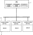
High speed processor system with low speed high capacity DRAM of a CPU and a band cache memory is well-known as a system that is used for the high speed processing large-scale data.As shown in Figure 1, known high speed processor system like this has the CPU 1 that comprises an one-level cache memory, with a plurality of parallel DRAM 2 that is connected to CPU 1 by common bus, each DRAM 2 disposes l2 cache memory 3, and l2 cache memory 3 is used to make the DRAM 2 can be with the velocity process near the processing speed of CPU 1.
In the operation of circuit shown in Figure 1, one content is read among a plurality of DRAM 2 in an instruction that provides according to CPU 1, and also according to from the instruction of CPU 1 information being write 2 li of DRAM.Hit if read instruction, if just cache memory 3 is preserved the content of the hope that will read from DRAM 2, then CPU 10 can carry out high-speed data by visit l2 cache memory 3 and handles.But, under the situation of not hitting, just, when not having the content of hope in the cache memory 3, need cache memory 3 to read object content so from DRAM 2.
Described basic configuration with high speed processor system of processor, DRAM and cache memory is occupied an leading position current, because it advantageously allows to use general coding style to be used for control.
This high speed processor system adopts the hierarchy type of cache memory to arrange, and still, it can not carry out parallel processing, because it adopts unique CPU 1.In addition, be not intended to be used for parallel processing on the general coding style inherence, and can not easily be used to move parallel processing system (PPS),, hindered actual use like this unless it is modified.
Disclosure of the Invention
In these cases, the purpose of this invention is to provide a kind of new high speed processor system, a kind of method of using this high speed processor system and a kind of recording medium that is used for the readable and computer executable program of logger computer.
Consider afore-mentioned, an object of the present invention is to provide a high speed processor system, this system can realize parallel processing and need not the conventional programming style is carried out any change or modification, provides a kind of and produces the method for this high speed processor system and a kind of logger computer is readable and the recording medium of computer executable program.
According to the present invention, a kind of high speed processor system is provided, comprise: CPU with an one-level cache memory; Be arranged on the l2 cache memory than the low level of CPU, this l2 cache memory has one the one MPU; Be connected to a plurality of primary memorys of l2 cache memory and parallel setting, each primary memory has the 3rd cache memory of being furnished with one the 2nd MPU; Wherein each of a MPU and the 2nd MPU all has the logic function and the functional processor of caches, therefore allows the parallel processing that distributes.
In high speed processor system of the present invention, the 3rd cache memory can have the line length bigger than l2 cache memory, and l2 cache memory has the line length bigger than one-level cache memory.
L2 cache memory visit as l2 cache memory by CPU and by a MPU as the one-level cache access.
The 3rd cache memory by CPU as the 3rd cache access, by a MPU visit as l2 cache memory and by the 2nd MPU as the one-level cache access.
The intelligent prefetched instruction that control protocol that each data processing of being carried out by a MPU and the 2nd MPU is carried according to a prefetched instruction or CPU provide is carried out.Simultaneously, each among a MPU and the 2nd MPU is carried out data processing selectively according to data transfer length and data transmitted frequency,
For example, a MPU mainly carries out the global transmission processing or hangs down calculation stage and the high transfer rate processing by data and program that use is stored in a plurality of primary memorys.The 2nd MPU mainly carries out the native object processing by data and program that use is stored in the relevant single primary memory.
High speed processor system can be realized as ASIC-DRAM with single chip.
The present invention also provides the method for using high speed processor system, and this system comprises the CPU with one-level cache memory; Be arranged on the l2 cache memory than the low hierarchical level of CPU, this l2 cache memory has one the one MPU; Be connected to a plurality of primary memorys of l2 cache memory and parallel setting, each primary memory has the 3rd cache memory of being furnished with the 2nd MPU; Described method comprises: make CPU mainly carry out senior calculation process; Making a MPU mainly carry out global transmission processing and rudimentary calculating and high rate data transmission handles; Make data and a program that is stored in the primary memory relevant by use among the 2nd MPU mainly carry out the native object processing, handle thereby carry out distributed parallel with the 2nd MPU.
The intelligent prefetched instruction that control protocol that each data processing of being carried out by a MPU and the 2nd MPU is carried according to prefetched instruction or CPU provide is carried out.Therefore, high speed processor is controlled with general coding style.
High speed processor system of the present invention can be achieved by comprising as lower member: the CPU with one-level cache memory, be connected to a plurality of primary memorys of CPU and parallel setting, each primary memory has and is furnished with the l2 cache memory that MPU provides; Wherein each MPU has logical cache memory function and functional processor, therefore can handle by distributed parallel.
Brief Description Of Drawings
Fig. 1 is the block scheme of a conventional parallel processor.
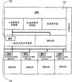
Fig. 2 is the block scheme of one embodiment of the present of invention.
Fig. 3 is the block scheme of a concrete instance of the chip layout of expression DRAM, MPU and cache memory.
Fig. 4 is the block scheme of the inner structure of expression l2 cache memory and MPU.
Fig. 5 is the synoptic diagram of the data stream of explanation under a common cache mode.
Fig. 6 is explanation at the distribute synoptic diagram of executory data stream of native object.
Fig. 7 is the synoptic diagram of explanation by the data stream in the transmission process of l2 cache memory execution.
Fig. 8 represents an intelligent prefetched instruction.
Fig. 9 is the synoptic diagram of the chip system of an ASIC DRAM of expression.
Realize preferred mode of the present invention
With reference to figs. 2 to Fig. 9 a preferred embodiment of the present invention is described.With reference to figure 2, high speed processor system has a CPU 10, it comprises an I cache memory (instruction cache) 10a as the one-level cache memory, D cache memory (data caching) 10b and scratchpad (scratch pad) storer 10c.(term " one-level cache memory " also is used to whole expression I cache memory 10a, D cache memory 10b and scratchpad 10c.) high speed processor system is connected to the unified cache memory 11 (being also referred to as " l2 cache memory ") of CPU 10 in addition.The minimum level of high speed processor system comprise a plurality of by bus and DRAM 13-1 to the 13-3 unified cache memory 12 that is connected parallel to each other (being also referred to as " the 3rd cache memory ").L2 cache memory and the 3rd cache memory are furnished with MPU (microprocessing unit) 16 and 14 respectively, as logical cache memory.
Each layer of configuration shown in Figure 2 uses one or more cache memories to be used to realize high speed processing.Arrange like this, make size as cache memory capacity unit, that is the line length of burst read/write length, greater than the line length of the cache memory of higher level for the cache memory of lower level.Configuration shown in Figure 2 is only in order to illustrate, and l2 cache memory 11 is optional.That is high speed processor system can have such configuration, and it comprises CPU 10 and a plurality of DRAM 13, and each DRAM13 has unified cache memory 12.
In arrangement shown in Figure 2, be used as MPU 16 and the MPU 14 and CPU 10 binary compatibles of the logical cache memory of l2 cache memory 12 and the 3rd cache memory 13.Among MPU 14 and the MPU 16 each has dual role: that is as the function of logical cache memory with as the function of processor.The cache memory function is the function that is used for control cache memory under the order of CPU10, and functional processor is the function that is used as a sub-CPU of distributed parallel system under the order of CPU 10.
Fig. 3 is the explanation of the high speed processor configuration of actual Fig. 2 that realizes on semi-conductor chip 15.That form on chip 15 is a DRAM array 13a, and it constitutes the major part of DRAM 13, detecting amplifier 13b, row address 13c, column address 13d, control circuit 13e and data input/output circuit 13f.Chip 15 shown in Figure 3 uses a SRAM 12 as cache memory.SRAM 12 is directly connected to detecting amplifier 13b, the latter to or from DRAM array 13a input and output data.SRAM 12 it self and data input/output circuit 13f between swap data.
Control by MPU 14 by the cache memory that SRAM 12 realizes with logical cache memory function and functional processor.About the logical cache memory function, SRAM 12 as simple unified cache memory, makes the read/write operation on the DRAM array 13a is carried out via SRAM 12 under the control of MPU 14.About processing capacity, in arrangement shown in Figure 2, for CPU 10, SRAM 12 is as the 3rd cache memory, make MPU 14 according to predetermined prefetched instruction executable operations, such as carrying out by being stored in reading in advance of object that program among the DRAM 13a and data form and data.
MPU 14 is driven by the prefetched instruction that CPU 10 provides.In general, the processing speed of processor system depends on interconnection CPU and storer and as the cache memory of high-speed memory, and why Here it is will actively accept to use the cause of cache memory.Especially, by using the pre-read data of prefetched instruction CPU.In the present invention, the prefetched instruction that is used for cache memory control further is applied to MPU 14, makes MPU 14 also can carry out processing.
In fact, MPU 14 can be combined in the cache memory of system by scalable RISC (Reduced Instruction Set Computer) CPU nuclear, this CPU endorses by for example ARM (advanced RISC machine) processor or the realization of MIPS (microprocessor of no interlocked pipeline stages) processor of relatively little nuclear, and they can realize high-performance CPU.
Fig. 4 explanation is in the actual arrangement of the interconnection between CPU 10 and l2 cache memory 11 shown in Figure 2.Basically, l2 cache memory 11 can be counted as the processor in conjunction with a unified cache memory 11a.The MPU 16 that carries out processing capacity for CPU 10 is used as l2 cache memory, and can be used as l2 cache memory work.Unified cache memory 11a in l2 cache memory is made up of a SRAM.When by CPU 10 visits, unified cache memory 11a is as the l2 cache memory of CPU 10.When by MPU 16 visits, unified cache memory 11a is used as the one-level cache memory of MPU 16.In Fig. 4, reference number 17 indications are used to be connected to the memory interface of DRAM 13.
As previously mentioned, l2 cache memory 11 has the burst read/write length bigger than the one-level cache memory that comprises I cache memory, D cache memory and scratchpad.According to the control protocol that CPU 10 provides, l2 cache memory 11 is as l2 cache memory work, and carries out simultaneously by the processing that is stored in the object that program in the 3rd cache memory and the primary memory and data form.Processing in this occasion mainly is need frequently to transmit data at DRAM 13-1 between the 13-3, rather than complex calculations to be handled.The prefetched instruction that the command execution that l2 cache memory 11 also provides according to CPU 10 is one type, they carry out than the MPU 14 of each the 3rd cache memory 12 those are more general and more complicated.For example, l2 cache memory 12 is carried out the prefetched instruction that relates to a plurality of DRAM.
Fig. 5 represents observed data stream when circuit shown in Figure 2 is operated under common cache memory approaches, wherein MPU 14 and 16 carry out the logical cache memory functions and do not carry out processing capacity.When CPU 10 pack processing were contained in data among the DRAM, it was by l2 cache memory 11 read datas.That is transmit data to l2 cache memory 11 from the 3rd secondary cache memory 12 of lowermost layer, and it is designed to have big relatively transmission length (once Chuan Shu data length) and relative low transfer rate.The data that are transferred to l2 cache memory 11 further are transferred to the one-level cache memory of highest level, and are consigned to CPU 10.Along the reverse execution of above-mentioned route to DRAM 13 write datas.
Therefore, repeatedly carry out visit data.As if effectively management of this mode that conducts interviews by the present available stack function (as the memory function that last in, first out) of CPU 10.Yet an actual problem of running into is, the data that must often visit gone out by speed buffering (cache-out) be by must only causing by CPU visit data once, such as the data that are used for image processing and the large-scale data that will be retrieved.This has caused the increase of useless access number.Described notion according to cache memory control of the present invention is based on the needs of eliminating or reducing the number of this useless access.
Available disposal system is designed to as shown in Figure 5 at present, supposes to have many access path.From a practical point of view, the memory construction of exercisable Fig. 5 is very useful under common programming.
With reference now to Fig. 6,, the data stream that expression realizes when the MPU 14 of the 3rd cache memory 12 carries out processing capacity among the figure.In this occasion, MPU 14 carries out the distribution process of native object.Therefore, need not handle by MPU 14 according to the control protocol that is included in the prefetched instruction that provides by CPU10 by the native object that CPU 10 handles.For example, the program or the data that are stored in the single DRAM piece are treated as native object, and accept such as only being incremental computations or determining peaked processing.Thereby may handle by using MPU 14 to carry out distributed parallel.Be appreciated that term of execution distributed parallel is handled native object is handled the DRAM piece of carrying out thereon and cushioned away from order cache memory buffering high speed.
Fig. 7 represents the data stream that realizes when the MPU in the l2 cache memory 11 16 carries out processing capacities.MPU 16 carries out the distribution process of object in predetermined scope.That is the control protocol that MPU 16 provides according to CPU 10 is carried out the processing that does not need by the object of CPU 10 processing.The example of the distribution process of being carried out by MPU 16 is that global transmission is handled and rudimentary calculating and high rate data transmission processing, for example, and the data transmission from a DRAM 13-1 to another DRAM 13-2.
Basically, MPU 16 can visit all storeies, makes its instead multicomputer system of carry out handling of CPU10.Yet MPU 16 is suitable for the global transmission of extensive transmission as large-scale data most, because its computing power is more much lower than CPU10.Therefore, MPU 16 carries out the processing that a class does not need the high computing power of CPU 10 or orders the sophisticated functions of one-level cache memory selectively.The processing of being carried out by MPU 16 is also under the control of the control protocol that CPU10 provides.
Fig. 8 illustrates an intelligent prefetched instruction.This intelligence prefetched instruction (IPREF) is as allowing control to be subordinated to the MPU 16 and 14 and do not need the conventional programming style is carried out the equipment of any change of CPU 10, and MPU 16 and 14 is attached to CPU 10.With reference to figure 8, CPU 10 has I cache memory 10a and D cache memory 10b.The problem of cache coherence occurs as processor by using MPU 16.That is, as may be inconsistent with the data that in the D of CPU 10 cache memory 10b, keep by the result's of MPU 16 executive routines data variation.For avoiding this problem, illustrated embodiment is so arranged, when CPU 10 indication MPU 16 carry out a certain operation, data in the D of CPU 10 cache memory 10b are gone out by speed buffering, and the new data (data designated) that the result who makes the content of D cache memory 10b be used as the program that MPU 16 carries out obtains upgrades.
Be a cache memory on MPU 16 inherences, so it can be used as cache memory control.For this purpose, MPU 16 instructs to carry out an operation with general cache memory according to the same mode of prefetched instruction work according to IPREF.Therefore this might by the IPREF instruction control simultaneously cache memory and MPU 16 both.Particularly, the effect of a prefetched instruction superhigh speed memory buffer of MPU16 response, and an operation is carried out in response IPREF instruction.
In other words, with reference to figure 8, IPREF is the extended instruction that CPU 10 provides.When carrying out, this extended instruction causes that certain appointed area among the D cache memory 10b gone out by speed buffering, and sends a control protocol for the cache memory of a low hierarchical level.When receiving control protocol, the MPU of the appointment of a low hierarchical level is by visiting the program of carrying out this agreement appointment to the memory block of a DRAM or a low hierarchical level, and data of wishing are put into cache memory.
Be expressed as an example of the retrieval of decision maximum value data below.
The maximal value * of data array among the IPREF DRAM 0/*DRAM 0/
The maximal value * of data array among the IPREF DRAM 1/*DRAM 1/
The maximal value * of data array among the IPREF DRAM 2/*DRAM 2/
The maximal value * of data array among the IPREF DRAM 3/*DRAM 3/
Load r0 DRAM1-MAX/* read among the DRAM 0 maximal value */
Load r1 DRAM1-MAX/* read among the DRAM 1 maximal value */
Load r2 DRAM1-MAX/* read among the DRAM 2 maximal value */
Load r3 DRAM1-MAX/* read among the DRAM 3 maximal value */
Max?r0,r0,r1
Max?r2,r2,r3
Max r0, r0, r2/* maximum value data retrieval end */
Supposition during this example has been deposited with from DRAMO to DRAM3 based on specific data shown in Figure 8.Instruction IPREF DRAMO is the instruction that is used to carry out a designated program to IPREF DRAM3.After the content of the appointed area in carrying out D cache memory 10b was gone out by speed buffering, the program of being deposited was carried out according to the IPREF instruction.This IPREF carries out to DRAM3 at DRAM0, and CPU 10 sends control protocol to DRAM0 to DRAM3.When in cache memory, maximal value being set, carry out load instructions.In this occasion, might comprise that eight instructions of four IPREF instructions and four load instructions decide four maximal values by use, but available peaked number depends on the transmission length of DRAM.Real maximal value can decide by checking the maximal value of obtaining one by one.
From above explanation as can be seen, according to the present invention, a processor system is provided, it has a plurality of cache memories, each cache memory is in conjunction with a MPU, and this MPU both can be used as logical cache memory and also can be used as the secondary processor of subsidiary layer.Use this processor system, can realize at a high speed and parallel processing efficiently, and need not the conventional programming style is made any modification.
Claims (23)
1. high speed processor system comprises:
CPU with one-level cache memory;
Be arranged on than the l2 cache memory on the low hierarchical level of described CPU, described l2 cache memory has a MPU;
Be connected to a plurality of primary memorys of described l2 cache memory and parallel setting, each described primary memory has the 3rd cache memory of being furnished with the 2nd MPU;
Wherein, each among a described MPU and described the 2nd MPU all has caches logic function and functional processor, thereby allows distributed parallel to handle.
2. according to the high speed processor system of claim 1, wherein, described the 3rd cache memory has the line length bigger than described l2 cache memory, and described l2 cache memory has than the bigger line length of described one-level cache memory.
3. according to the high speed processor system of claim 1, wherein, a described MPU and described the 2nd MPU and described CPU binary compatible.
4. according to the high speed processor system of claim 1, wherein, each described l2 cache memory and described the 3rd cache memory are realized by a unified cache memory.
5. according to the high speed processor system of claim 1, wherein, described l2 cache memory is visited as l2 cache memory by described CPU, by a described MPU as the one-level cache access.
6. according to the high speed processor system of claim 1, wherein, described the 3rd cache memory, is visited as l2 cache memory by a described MPU as the 3rd cache access by described CPU, by described the 2nd MPU as the one-level cache access.
7. according to the high speed processor system of claim 1, wherein, carry out according to the control protocol of carrying or by the intelligent prefetched instruction that described CPU provides by a prefetched instruction by each data processing that a described MPU and described the 2nd MPU carry out.
8. according to the high speed processor system of claim 1, wherein, each among a described MPU and described the 2nd MPU is carried out data processing selectively according to data transmission length and data transmission frequency.
9. according to the high speed processor system of claim 1, wherein, a described MPU mainly carries out the global transmission processing or hangs down calculation stage and the high transfer rate processing by data and program that use is stored in described a plurality of primary memory.
10. according to the high speed processor system of claim 1, wherein, each described the 2nd MPU mainly carries out the native object processing by data and program that use is stored in the relevant single primary memory.
11. according to the high speed processor system of claim 1, wherein, described primary memory is realized by DRAM, and described l2 cache memory is realized by SRAM.
12. according to the high speed processor system of claim 1, it is realized with the single chip as ASIC-DRAM.
13. a method of using high speed processor system, this high speed processor system comprises the CPU with one-level cache memory; Be arranged on the l2 cache memory than the low hierarchical level of described CPU, described l2 cache memory has a MPU; Be connected to a plurality of primary memorys of described l2 cache memory and parallel setting, each described primary memory has the 3rd cache memory of being furnished with the 2nd MPU; Described method comprises:
Make described CPU mainly carry out senior calculation process;
Making a described MPU mainly carry out global transmission handles and hangs down calculation stage and high transmission rates is handled;
Make data and a program that is stored in the described primary memory relevant by use among described the 2nd MPU mainly carry out the native object processing, handle thereby carry out distributed parallel with the 2nd MPU.
14. according to the method for the use high speed processor system of claim 13, wherein, the intelligent prefetched instruction that control protocol that each data processing of being carried out by a described MPU and described the 2nd MPU is carried according to a prefetched instruction or CPU provide is carried out.
15. according to the method for the use high speed processor system of claim 13, wherein, described high speed processor is controlled with common coding style.
16. according to the method for the use high speed processor system of claim 13, wherein, when at least one of described the 2nd MPU carried out data processing function and come deal with data, the piece under the MPU was gone out by speed buffering.
17. a high speed processor system comprises:
CPU with one-level cache memory;
Be connected to a plurality of primary memorys of described CPU and parallel setting, each described primary memory has the l2 cache memory of being furnished with a MPU;
Wherein each described MPU has logical cache memory function and functional processor, thereby allows distributed parallel to handle.
18. according to the high speed processor system of claim 17, wherein, each described l2 cache memory is realized by a unified cache memory.
19. according to the high speed processor system of claim 17, wherein, described l2 cache memory is visited as l2 cache memory by described CPU, by described MPU as the one-level cache access.
20. according to the high speed processor system of claim 17, wherein, the control protocol that the data processing of being undertaken by a plurality of described MPU is carried according to a prefetched instruction or carry out by the intelligent prefetched instruction that described CPU provides.
21. according to the high speed processor system of claim 17, wherein, each described MPU mainly carries out the native object processing by data and program that use is stored in the relevant single primary memory.
22. according to the high speed processor system of claim 17, wherein, described primary memory is realized by DRAM, and described l2 cache memory is realized by SRAM.
23., realize with single chip as ASIC-DRAM according to the high speed processor system of claim 17.
Applications Claiming Priority (2)
| Application Number | Priority Date | Filing Date | Title |
|---|---|---|---|
| JP13486/99 | 1999-01-21 | ||
| JP1348699 | 1999-01-21 |
Publications (2)
| Publication Number | Publication Date |
|---|---|
| CN1341242A CN1341242A (en) | 2002-03-20 |
| CN100483389C true CN100483389C (en) | 2009-04-29 |
Family
ID=11834461
Family Applications (1)
| Application Number | Title | Priority Date | Filing Date |
|---|---|---|---|
| CNB008029830A Expired - Lifetime CN100483389C (en) | 1999-01-21 | 2000-01-21 | High-speed processor system, method of using the same, and recording medium |
Country Status (15)
| Country | Link |
|---|---|
| US (3) | US6578110B1 (en) |
| EP (2) | EP1445701A3 (en) |
| JP (1) | JP3698358B2 (en) |
| KR (1) | KR100678372B1 (en) |
| CN (1) | CN100483389C (en) |
| AT (1) | ATE266884T1 (en) |
| AU (1) | AU3075600A (en) |
| BR (1) | BR0008905A (en) |
| CA (1) | CA2364338A1 (en) |
| DE (1) | DE60010674T2 (en) |
| ES (1) | ES2220386T3 (en) |
| HK (1) | HK1039809A1 (en) |
| RU (1) | RU2001122104A (en) |
| TW (1) | TW472197B (en) |
| WO (1) | WO2000043902A1 (en) |
Cited By (1)
| Publication number | Priority date | Publication date | Assignee | Title |
|---|---|---|---|---|
| CN104956342A (en) * | 2013-02-05 | 2015-09-30 | Arm有限公司 | Virtualization supporting guest operating systems using memory protection units |
Families Citing this family (39)
| Publication number | Priority date | Publication date | Assignee | Title |
|---|---|---|---|---|
| GB0125711D0 (en) * | 2001-10-26 | 2001-12-19 | Ibm | In-memory arithmetic |
| US7133972B2 (en) * | 2002-06-07 | 2006-11-07 | Micron Technology, Inc. | Memory hub with internal cache and/or memory access prediction |
| US7117316B2 (en) | 2002-08-05 | 2006-10-03 | Micron Technology, Inc. | Memory hub and access method having internal row caching |
| US6820181B2 (en) | 2002-08-29 | 2004-11-16 | Micron Technology, Inc. | Method and system for controlling memory accesses to memory modules having a memory hub architecture |
| US7120743B2 (en) | 2003-10-20 | 2006-10-10 | Micron Technology, Inc. | Arbitration system and method for memory responses in a hub-based memory system |
| US7330992B2 (en) | 2003-12-29 | 2008-02-12 | Micron Technology, Inc. | System and method for read synchronization of memory modules |
| US8301788B2 (en) * | 2004-09-10 | 2012-10-30 | Cavium, Inc. | Deterministic finite automata (DFA) instruction |
| US8392590B2 (en) * | 2004-09-10 | 2013-03-05 | Cavium, Inc. | Deterministic finite automata (DFA) processing |
| US8560475B2 (en) | 2004-09-10 | 2013-10-15 | Cavium, Inc. | Content search mechanism that uses a deterministic finite automata (DFA) graph, a DFA state machine, and a walker process |
| US20070005902A1 (en) * | 2004-12-07 | 2007-01-04 | Ocz Technology Group, Inc. | Integrated sram cache for a memory module and method therefor |
| US7653785B2 (en) * | 2005-06-22 | 2010-01-26 | Lexmark International, Inc. | Reconfigurable cache controller utilizing multiple ASIC SRAMS |
| US8819217B2 (en) * | 2007-11-01 | 2014-08-26 | Cavium, Inc. | Intelligent graph walking |
| US8180803B2 (en) * | 2007-11-27 | 2012-05-15 | Cavium, Inc. | Deterministic finite automata (DFA) graph compression |
| US7949683B2 (en) * | 2007-11-27 | 2011-05-24 | Cavium Networks, Inc. | Method and apparatus for traversing a compressed deterministic finite automata (DFA) graph |
| JP2010015233A (en) * | 2008-07-01 | 2010-01-21 | Panasonic Corp | Integrated circuit and electronic apparatus |
| US8473523B2 (en) | 2008-10-31 | 2013-06-25 | Cavium, Inc. | Deterministic finite automata graph traversal with nodal bit mapping |
| US9274950B2 (en) * | 2009-08-26 | 2016-03-01 | Hewlett Packard Enterprise Development Lp | Data restructuring in multi-level memory hierarchies |
| US8331123B2 (en) * | 2009-09-21 | 2012-12-11 | Ocz Technology Group, Inc. | High performance solid-state drives and methods therefor |
| US20130318280A1 (en) * | 2012-05-22 | 2013-11-28 | Xockets IP, LLC | Offloading of computation for rack level servers and corresponding methods and systems |
| JP6228523B2 (en) * | 2014-09-19 | 2017-11-08 | 東芝メモリ株式会社 | Memory control circuit and semiconductor memory device |
| CN105608490B (en) * | 2015-07-29 | 2018-10-26 | 上海磁宇信息科技有限公司 | Cellular array computing system and communication means therein |
| CN105718379B (en) * | 2015-07-29 | 2018-09-14 | 上海磁宇信息科技有限公司 | Cellular array computing system and wherein iuntercellular mass-send communication means |
| CN105718994B (en) * | 2015-07-29 | 2019-02-19 | 上海磁宇信息科技有限公司 | Cellular array computing system |
| CN105718996B (en) * | 2015-07-29 | 2019-02-19 | 上海磁宇信息科技有限公司 | Cellular array computing system and communication means therein |
| CN105718993B (en) * | 2015-07-29 | 2019-02-19 | 上海磁宇信息科技有限公司 | Cellular array computing system and communication means therein |
| CN105718992B (en) * | 2015-07-29 | 2019-02-19 | 上海磁宇信息科技有限公司 | Cellular array computing system |
| CN105740946B (en) * | 2015-07-29 | 2019-02-12 | 上海磁宇信息科技有限公司 | A kind of method that application cell array computation system realizes neural computing |
| CN105718995B (en) * | 2015-07-29 | 2019-02-01 | 上海磁宇信息科技有限公司 | Cellular array computing system and its adjustment method |
| CN105718991B (en) * | 2015-07-29 | 2019-02-19 | 上海磁宇信息科技有限公司 | Cellular array computing system |
| CN105718990B (en) * | 2015-07-29 | 2019-01-29 | 上海磁宇信息科技有限公司 | Communication means between cellular array computing system and wherein cell |
| CN105718380B (en) * | 2015-07-29 | 2019-06-04 | 上海磁宇信息科技有限公司 | Cellular array computing system |
| CN105718392B (en) * | 2016-01-15 | 2019-01-29 | 上海磁宇信息科技有限公司 | Cellular array document storage system and its file-storage device and file memory method |
| GB2542646B (en) * | 2016-03-18 | 2017-11-15 | Imagination Tech Ltd | Non-linear cache logic |
| CN107291209B (en) * | 2016-04-01 | 2021-02-09 | 上海磁宇信息科技有限公司 | Cell array computing system |
| US10409754B2 (en) * | 2016-04-28 | 2019-09-10 | Smart Modular Technologies, Inc. | Interconnected memory system and method of operation thereof |
| CN107341129B (en) * | 2016-04-29 | 2021-06-29 | 上海磁宇信息科技有限公司 | Cell array computing system and testing method thereof |
| JP6493318B2 (en) * | 2016-06-24 | 2019-04-03 | 株式会社デンソー | Data processing system |
| GB2553102B (en) * | 2016-08-19 | 2020-05-20 | Advanced Risc Mach Ltd | A memory unit and method of operation of a memory unit to handle operation requests |
| KR102631380B1 (en) * | 2018-05-17 | 2024-02-01 | 에스케이하이닉스 주식회사 | Semiconductor system including various memory deivces capable of processing data |
Family Cites Families (23)
| Publication number | Priority date | Publication date | Assignee | Title |
|---|---|---|---|---|
| JP2539385B2 (en) * | 1986-08-08 | 1996-10-02 | 株式会社日立製作所 | Information processing device |
| AU2278688A (en) | 1988-02-16 | 1989-08-17 | Sun Microsystems, Inc. | Distributed cache architecture |
| JPH0239339A (en) | 1988-07-29 | 1990-02-08 | Hitachi Ltd | Cache memory device |
| US5226169A (en) * | 1988-12-30 | 1993-07-06 | International Business Machines Corp. | System for execution of storage-immediate and storage-storage instructions within cache buffer storage |
| EP0375883A3 (en) | 1988-12-30 | 1991-05-29 | International Business Machines Corporation | Cache storage system |
| JPH033047A (en) | 1989-05-31 | 1991-01-09 | Nec Corp | Memory with arithmetic function |
| DE69132495T2 (en) * | 1990-03-16 | 2001-06-13 | Texas Instruments Inc | Distributed processing memory |
| US5617577A (en) * | 1990-11-13 | 1997-04-01 | International Business Machines Corporation | Advanced parallel array processor I/O connection |
| US5260898A (en) | 1992-03-13 | 1993-11-09 | Sun Microsystems, Inc. | Result cache for complex arithmetic units |
| US6000027A (en) * | 1992-08-25 | 1999-12-07 | Texas Instruments Incorporated | Method and apparatus for improved graphics/image processing using a processor and a memory |
| KR940004434A (en) * | 1992-08-25 | 1994-03-15 | 윌리엄 이. 힐러 | Smart Dynamic Random Access Memory and Its Processing Method |
| JP3207591B2 (en) | 1993-03-19 | 2001-09-10 | 株式会社日立製作所 | Improvement of computer with cache memory |
| US6226722B1 (en) * | 1994-05-19 | 2001-05-01 | International Business Machines Corporation | Integrated level two cache and controller with multiple ports, L1 bypass and concurrent accessing |
| DE19540915A1 (en) * | 1994-11-10 | 1996-05-15 | Raymond Engineering | Redundant arrangement of solid state memory modules |
| US5778436A (en) * | 1995-03-06 | 1998-07-07 | Duke University | Predictive caching system and method based on memory access which previously followed a cache miss |
| US5900011A (en) | 1996-07-01 | 1999-05-04 | Sun Microsystems, Inc. | Integrated processor/memory device with victim data cache |
| US5848254A (en) | 1996-07-01 | 1998-12-08 | Sun Microsystems, Inc. | Multiprocessing system using an access to a second memory space to initiate software controlled data prefetch into a first address space |
| JP3075183B2 (en) | 1996-07-17 | 2000-08-07 | 日本電気株式会社 | Cache memory system |
| US5895487A (en) * | 1996-11-13 | 1999-04-20 | International Business Machines Corporation | Integrated processing and L2 DRAM cache |
| JPH10214223A (en) | 1997-01-29 | 1998-08-11 | Hitachi Ltd | Information processing system |
| US5987577A (en) * | 1997-04-24 | 1999-11-16 | International Business Machines | Dual word enable method and apparatus for memory arrays |
| US6192451B1 (en) * | 1998-02-17 | 2001-02-20 | International Business Machines Corporation | Cache coherency protocol for a data processing system including a multi-level memory hierarchy |
| US6453398B1 (en) * | 1999-04-07 | 2002-09-17 | Mitsubishi Electric Research Laboratories, Inc. | Multiple access self-testing memory |
-
2000
- 2000-01-20 US US09/488,405 patent/US6578110B1/en not_active Expired - Lifetime
- 2000-01-21 EP EP04011042A patent/EP1445701A3/en not_active Withdrawn
- 2000-01-21 JP JP2000595256A patent/JP3698358B2/en not_active Expired - Fee Related
- 2000-01-21 DE DE60010674T patent/DE60010674T2/en not_active Expired - Lifetime
- 2000-01-21 AU AU30756/00A patent/AU3075600A/en not_active Abandoned
- 2000-01-21 CA CA002364338A patent/CA2364338A1/en not_active Abandoned
- 2000-01-21 EP EP00900858A patent/EP1161729B1/en not_active Expired - Lifetime
- 2000-01-21 CN CNB008029830A patent/CN100483389C/en not_active Expired - Lifetime
- 2000-01-21 WO PCT/JP2000/000278 patent/WO2000043902A1/en active IP Right Grant
- 2000-01-21 TW TW089100987A patent/TW472197B/en not_active IP Right Cessation
- 2000-01-21 AT AT00900858T patent/ATE266884T1/en not_active IP Right Cessation
- 2000-01-21 ES ES00900858T patent/ES2220386T3/en not_active Expired - Lifetime
- 2000-01-21 BR BR0008905-2A patent/BR0008905A/en not_active Application Discontinuation
- 2000-01-21 KR KR1020017009201A patent/KR100678372B1/en not_active IP Right Cessation
- 2000-01-21 RU RU2001122104/09A patent/RU2001122104A/en not_active Application Discontinuation
-
2002
- 2002-02-06 HK HK02100939.2A patent/HK1039809A1/en unknown
-
2003
- 2003-04-24 US US10/422,117 patent/US6745290B2/en not_active Expired - Lifetime
-
2004
- 2004-04-20 US US10/827,749 patent/US7028141B2/en not_active Expired - Lifetime
Non-Patent Citations (4)
| Title |
|---|
| complementary hybrid architecture with two differentprocessing elements with different grain size. HIRAKI K ET AL.proceedings of the region10 annual international conference(tencon),us,NEW YORK,IEEE,Vol.vol,CONF.9 No.xp000529495. 1994 |
| complementary hybrid architecture with two differentprocessing elements with different grain size. HIRAKI K ET AL.proceedings of the region10 annual international conference(tencon),us,NEW YORK,IEEE,Vol.CONF.9 No.xp000529495. 1994 * |
| missing the memory wall:the case for processor/memoryintegration. SAULSBURY A ET AL.proceedings of the annual symposium on computer architecture,us,NEW YORK,ACM/IEEE,Vol.vol.SYMP.23 No.xp000679345. 1996 |
| missing the memory wall:the case for processor/memoryintegration. SAULSBURY A ET AL.proceedings of the annual symposium on computer architecture,us,NEW YORK,ACM/IEEE,Vol.SYMP.23 No.xp000679345. 1996 * |
Cited By (1)
| Publication number | Priority date | Publication date | Assignee | Title |
|---|---|---|---|---|
| CN104956342A (en) * | 2013-02-05 | 2015-09-30 | Arm有限公司 | Virtualization supporting guest operating systems using memory protection units |
Also Published As
| Publication number | Publication date |
|---|---|
| JP3698358B2 (en) | 2005-09-21 |
| ES2220386T3 (en) | 2004-12-16 |
| CA2364338A1 (en) | 2000-07-27 |
| US6578110B1 (en) | 2003-06-10 |
| TW472197B (en) | 2002-01-11 |
| EP1161729A1 (en) | 2001-12-12 |
| US20040215881A1 (en) | 2004-10-28 |
| RU2001122104A (en) | 2003-06-27 |
| US20030217228A1 (en) | 2003-11-20 |
| HK1039809A1 (en) | 2002-05-10 |
| US7028141B2 (en) | 2006-04-11 |
| BR0008905A (en) | 2001-11-06 |
| EP1161729B1 (en) | 2004-05-12 |
| WO2000043902A1 (en) | 2000-07-27 |
| JP2002535777A (en) | 2002-10-22 |
| KR100678372B1 (en) | 2007-02-05 |
| US6745290B2 (en) | 2004-06-01 |
| CN1341242A (en) | 2002-03-20 |
| KR20010101628A (en) | 2001-11-14 |
| DE60010674T2 (en) | 2005-06-16 |
| EP1445701A3 (en) | 2009-03-25 |
| EP1445701A2 (en) | 2004-08-11 |
| ATE266884T1 (en) | 2004-05-15 |
| DE60010674D1 (en) | 2004-06-17 |
| AU3075600A (en) | 2000-08-07 |
Similar Documents
| Publication | Publication Date | Title |
|---|---|---|
| CN100483389C (en) | High-speed processor system, method of using the same, and recording medium | |
| JP4956922B2 (en) | Storage device | |
| CN100440177C (en) | Method for software controllable dynamically lockable cache line replacement system | |
| US6782454B1 (en) | System and method for pre-fetching for pointer linked data structures | |
| CN112558889B (en) | Stacked Cache system based on SEDRAM, control method and Cache device | |
| CN100394407C (en) | Low latency time memorizer system access | |
| CN106484628A (en) | Mixing memory module based on affairs | |
| JP2007520813A (en) | Multiprocessor computing system using word of information of compressed cache line and processor usable in the system | |
| US5038278A (en) | Cache with at least two fill rates | |
| US20140040541A1 (en) | Method of managing dynamic memory reallocation and device performing the method | |
| CN101390047A (en) | Data processing system and method for prefetching data and/or instructions | |
| CN107015923A (en) | Uniformity for managing snoop operations is interconnected and data processing equipment including it | |
| CN101111828A (en) | System and method for a memory with combined line and word access | |
| JP5338859B2 (en) | Storage device and information processing system | |
| TW202134956A (en) | Shared scratchpad memory with parallel load-store | |
| CN108268391A (en) | Semiconductor system and its control method | |
| KR102353859B1 (en) | Computing device and non-volatile dual in-line memory module | |
| JP7013360B2 (en) | Information processing equipment, information processing methods, and programs | |
| JP4656565B2 (en) | High speed processor system, method and recording medium using the same | |
| MXPA01007416A (en) | High-speed processor system, method of using the same, and recording medium | |
| US20030217232A1 (en) | Data transfer unit with support for multiple coherency granules | |
| JP2000047942A (en) | Device and method for controlling cache memory | |
| CA1314107C (en) | Cache with at least two different fill sizes | |
| KR920005296B1 (en) | Information processing device | |
| JP2645477B2 (en) | Microprocessor and its cache memory |
Legal Events
| Date | Code | Title | Description |
|---|---|---|---|
| C06 | Publication | ||
| PB01 | Publication | ||
| C10 | Entry into substantive examination | ||
| SE01 | Entry into force of request for substantive examination | ||
| C14 | Grant of patent or utility model | ||
| GR01 | Patent grant | ||
| CX01 | Expiry of patent term | ||
| CX01 | Expiry of patent term |
Granted publication date: 20090429 |