CN100477385C - Circuit board terminal - Google Patents
Circuit board terminal Download PDFInfo
- Publication number
- CN100477385C CN100477385C CNB011432942A CN01143294A CN100477385C CN 100477385 C CN100477385 C CN 100477385C CN B011432942 A CNB011432942 A CN B011432942A CN 01143294 A CN01143294 A CN 01143294A CN 100477385 C CN100477385 C CN 100477385C
- Authority
- CN
- China
- Prior art keywords
- terminal
- circuit board
- row
- terminals
- grounding terminals
- Prior art date
- Legal status (The legal status is an assumption and is not a legal conclusion. Google has not performed a legal analysis and makes no representation as to the accuracy of the status listed.)
- Expired - Lifetime
Links
Images


Classifications
-
- B—PERFORMING OPERATIONS; TRANSPORTING
- B41—PRINTING; LINING MACHINES; TYPEWRITERS; STAMPS
- B41J—TYPEWRITERS; SELECTIVE PRINTING MECHANISMS, i.e. MECHANISMS PRINTING OTHERWISE THAN FROM A FORME; CORRECTION OF TYPOGRAPHICAL ERRORS
- B41J2/00—Typewriters or selective printing mechanisms characterised by the printing or marking process for which they are designed
- B41J2/005—Typewriters or selective printing mechanisms characterised by the printing or marking process for which they are designed characterised by bringing liquid or particles selectively into contact with a printing material
- B41J2/01—Ink jet
- B41J2/17—Ink jet characterised by ink handling
- B41J2/175—Ink supply systems ; Circuit parts therefor
- B41J2/17503—Ink cartridges
- B41J2/17543—Cartridge presence detection or type identification
- B41J2/17546—Cartridge presence detection or type identification electronically
-
- B—PERFORMING OPERATIONS; TRANSPORTING
- B41—PRINTING; LINING MACHINES; TYPEWRITERS; STAMPS
- B41J—TYPEWRITERS; SELECTIVE PRINTING MECHANISMS, i.e. MECHANISMS PRINTING OTHERWISE THAN FROM A FORME; CORRECTION OF TYPOGRAPHICAL ERRORS
- B41J2/00—Typewriters or selective printing mechanisms characterised by the printing or marking process for which they are designed
- B41J2/005—Typewriters or selective printing mechanisms characterised by the printing or marking process for which they are designed characterised by bringing liquid or particles selectively into contact with a printing material
- B41J2/01—Ink jet
- B41J2/17—Ink jet characterised by ink handling
- B41J2/175—Ink supply systems ; Circuit parts therefor
- B41J2/17503—Ink cartridges
- B41J2/17526—Electrical contacts to the cartridge
- B41J2/1753—Details of contacts on the cartridge, e.g. protection of contacts
-
- H—ELECTRICITY
- H05—ELECTRIC TECHNIQUES NOT OTHERWISE PROVIDED FOR
- H05K—PRINTED CIRCUITS; CASINGS OR CONSTRUCTIONAL DETAILS OF ELECTRIC APPARATUS; MANUFACTURE OF ASSEMBLAGES OF ELECTRICAL COMPONENTS
- H05K1/00—Printed circuits
- H05K1/02—Details
- H05K1/11—Printed elements for providing electric connections to or between printed circuits
- H05K1/117—Pads along the edge of rigid circuit boards, e.g. for pluggable connectors
-
- H—ELECTRICITY
- H05—ELECTRIC TECHNIQUES NOT OTHERWISE PROVIDED FOR
- H05K—PRINTED CIRCUITS; CASINGS OR CONSTRUCTIONAL DETAILS OF ELECTRIC APPARATUS; MANUFACTURE OF ASSEMBLAGES OF ELECTRICAL COMPONENTS
- H05K2201/00—Indexing scheme relating to printed circuits covered by H05K1/00
- H05K2201/09—Shape and layout
- H05K2201/09209—Shape and layout details of conductors
- H05K2201/09372—Pads and lands
- H05K2201/09409—Multiple rows of pads, lands, terminals or dummy patterns; Multiple rows of mounted components
-
- H—ELECTRICITY
- H05—ELECTRIC TECHNIQUES NOT OTHERWISE PROVIDED FOR
- H05K—PRINTED CIRCUITS; CASINGS OR CONSTRUCTIONAL DETAILS OF ELECTRIC APPARATUS; MANUFACTURE OF ASSEMBLAGES OF ELECTRICAL COMPONENTS
- H05K2201/00—Indexing scheme relating to printed circuits covered by H05K1/00
- H05K2201/09—Shape and layout
- H05K2201/09209—Shape and layout details of conductors
- H05K2201/09654—Shape and layout details of conductors covering at least two types of conductors provided for in H05K2201/09218 - H05K2201/095
- H05K2201/09709—Staggered pads, lands or terminals; Parallel conductors in different planes
-
- H—ELECTRICITY
- H05—ELECTRIC TECHNIQUES NOT OTHERWISE PROVIDED FOR
- H05K—PRINTED CIRCUITS; CASINGS OR CONSTRUCTIONAL DETAILS OF ELECTRIC APPARATUS; MANUFACTURE OF ASSEMBLAGES OF ELECTRICAL COMPONENTS
- H05K2201/00—Indexing scheme relating to printed circuits covered by H05K1/00
- H05K2201/10—Details of components or other objects attached to or integrated in a printed circuit board
- H05K2201/10007—Types of components
- H05K2201/10159—Memory
Abstract
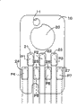
Circuit board (10) is of substantially rectangular shape, provided in the upper half of the juxtaposed face (13) with a substantially circular test terminal (20). In the lower half are provided a plurality of substantially rectangular terminals (21-27), arrayed in two rows, i.e., an upper and lower row, the upper row containing an I/O terminal (21) for data input/output, a power supply terminal (22) for supplying power, and a chip select terminal (23) for input of a chip select signal CS. The lower row of juxtaposed face (13) contains a ground terminal (24), a read/write terminal (25) for inputting read/write control signals W/R, a clock terminal (26) for inputting a clock signal CLK, and a ground terminal (27).
Description
Technical field
The present invention relates to a kind of circuit board, be used for the marker material container of splendid attire franking material.
Background technology
In recent years, developed the print cartridge of the circuit board of being furnished with the band storage device, this storage device is used for storing the data relevant with the China ink that is contained in print cartridge.The sort circuit plate is equipped with a plurality of terminals, is used for receiving from printer the data of power, storage, perhaps sends the data of being stored to printer.
Below with reference to Figure 12 the arrangement of conventional terminal is described.Circuit board 500 has: first terminal row, the read/write signal terminal 530 that has the grounding terminals 510 that is positioned at its center, the data I/O terminal 520 that is positioned at first side and be positioned at second side; With second terminal row, be positioned on first terminal row chip select signal terminal 560 that has the power terminal 540 that is positioned at the center, the clock signal terminal 550 that is positioned at first side and be positioned at second side.
But the problem that has existed in the past is, even forms under the situation about contact between the terminal 510-560 that causes owing to the misalignment of circuit board 500 etc. and contact pilotage 570, sense to be electrically connected, and therefore definite print cartridge installed.Final problem in these situations is, although judge and print cartridge be installed, and the data of being stored in can not read storage device.
Summary of the invention
Consider this problem, the object of the present invention is to provide a kind of arrangement of circuit board terminal, its permission accurately detects the situation that contacts with the circuit board terminal.Another purpose is to provide a kind of marker material container, and the accurate detection that provides the marker material container whether to install is provided.
For addressing this problem, a first aspect of the present invention provides a kind of circuit board that has storage device, described storage device is used to store the data relevant with the franking material, described circuit board comprises: at least two grounding terminals are arranged in the both sides on the axle that is positioned at circuit board of described circuit board; With a plurality of terminals that are arranged on the described circuit board, be used for the described data relevant with the franking material are carried out read/write operation, wherein said a plurality of terminal comprises power terminal and control signal terminal, and described a plurality of terminal and described grounding terminals are lined up single file, and described at least two grounding terminals are not nearest terminal of the described power terminal of distance and the outermost end that is positioned at described row.According to the circuit board of first aspect, have at least two grounding terminals herein, be arranged in the both sides on the same axle of being positioned at of described circuit board, thereby the accurate detection that contacts with terminal on the circuit board is provided.
In the circuit board of first aspect, described a plurality of terminals and described grounding terminals can be arranged in the single file herein, simultaneously two outermost end that are positioned at described row in described at least two grounding terminals.Because this arrangement, just can accurately detect with circuit board on the contacting of terminal.
In the circuit board of first aspect, described a plurality of terminals can be arranged in multirow herein, and simultaneously two in described at least two grounding terminals are arranged in the outermost end of described multirow delegation.Described a plurality of terminal can comprise clock signal terminal, and between described clock signal terminal two in described at least two grounding terminals.Because this arrangement can stable clock signal.In addition, described a plurality of terminals can comprise power terminal, and two outermost end that are positioned at certain delegation in described at least two grounding terminals, and this row is different from the row that comprises described power terminal.This arrangement prevents to be short-circuited between power terminal and the grounding terminals.
In the circuit board of first aspect, described a plurality of terminals can comprise power terminal and control signal terminal herein, and described at least two grounding terminals are not from the nearest terminal of described power terminal.This arrangement prevents to be short-circuited between power terminal and the grounding terminals.
In the circuit board of first aspect, described a plurality of terminals can comprise data I/O terminal, power terminal, selection Signal Terminal, read terminal and power terminal, and described multirow comprises herein:
First the row, wherein said data I/O terminal and described selection Signal Terminal be positioned at described power terminal both sides and
Second the row, wherein said read terminal and described power terminal between described two grounding terminals,
Described first row is than the centralized positioning of the more approaching described circuit board of described second row, and the described terminal in described terminal in described first row and described second row is arranged in the mode that replaces.This arrangement prevents to be short-circuited between these terminals, and prevents undesirable terminal contact.
In the circuit board of first aspect, described a plurality of terminals are with about 1 millimeter being spaced in the formation direction of described each row herein.
In second aspect, the invention provides a kind of circuit board that has storage device, described storage device is used to store the data relevant with the franking material, and described circuit board comprises: at least two grounding terminals are arranged in the both sides on the axle that is positioned at circuit board of described circuit board; With a plurality of terminals that are arranged on the described circuit board, be used for the described data relevant with the franking material are carried out read/write operation, wherein said a plurality of terminal comprises power terminal and control signal terminal, and described a plurality of terminal and described grounding terminals are aligned to multirow, and described at least two grounding terminals are not nearest terminal of the described power terminal of distance and the outermost end that is positioned at one of described multirow.According to the circuit board of second aspect, two grounding terminals are arranged in the both sides of circuit board herein, thereby the accurate detection that contacts with terminal on the circuit board is provided.
In the circuit board of second aspect, described a plurality of terminals can form a plurality of row parallel with a side of described circuit board herein, and described two grounding terminals can be arranged in the outermost end of certain delegation in the described multirow.Described a plurality of terminal comprises clock signal terminal, control signal terminal, and power terminal, and described two terminals are positioned at the outermost end of delegation, and this row is different from and comprises going and comprising the row of described clock signal terminal of described power terminal.This arrangement can provide and the effect of similarly working according to the first aspect circuit board.
In the third aspect, the invention provides a kind of marker material container of using with printing equipment of being configured to, comprise the vessel that is used for the described marker material of splendid attire; With circuit board with storage device, described storage device is used for storing the data relevant with the marker material that is contained in described vessel, described circuit board has a plurality of terminals of arranging along an axle of described circuit board thereon, at least two grounding terminals with both sides on the described axle that is positioned at described circuit board that is arranged in described circuit board, wherein said a plurality of terminal and described grounding terminals are arranged in the single file, and two grounding terminals in described at least two grounding terminals are not nearest terminal of the described power terminal of distance and the outermost end that is positioned at described row.In relevant with the third aspect herein marker material container, a kind of circuit board that is arranged with at least two grounding terminals on it is provided, described two grounding terminals are positioned on the both sides on one the axle, thereby whether the accurate detection of adjustment notch containers is provided.Marker material is used for print text and/or image.
In the marker material container according to the third aspect, described a plurality of terminals and described terminal can be arranged in the single file herein, simultaneously two outermost end that are positioned at described row in described at least two grounding terminals.Described a plurality of terminal can be arranged in multirow, and simultaneously two in described at least two grounding terminals are arranged in the outermost end of described multirow delegation.Whether these are arranged also provides the accurate detection of adjustment notch containers.
Herein in the marker material container according to the third aspect, described a plurality of terminal can comprise power terminal, control signal terminal and clock signal terminal, two outermost end that are positioned at this delegation in described at least two grounding terminals of while, this row is different from the row that comprises described power terminal, and is arranged in delegation with described clock signal terminal.This arrangement can stable clock signal, and prevents the short circuit between grounding terminals and the power terminal.
In the marker material container according to the third aspect, described a plurality of terminals can comprise data I/O terminal, power terminal, selection Signal Terminal, read terminal and power terminal herein; And described multirow comprises: first row, and wherein said data I/O terminal and described selection Signal Terminal are positioned at the both sides of described power terminal; With second row, wherein said read terminal and described power terminal are between described two grounding terminals; Described first row is than the centralized positioning of the more approaching described circuit board of described second row, and the described terminal in described terminal in described first row and described second row is arranged in the mode that replaces.This arrangement prevents to be short-circuited between these terminals, and prevents undesirable terminal contact.
In the marker material container according to the third aspect, described a plurality of terminals are arranged by the direction that described each row forms with the interval of about 1mm herein.Though the marker material container install the terminal contact fault that may cause on the circuit board incorrectly because this arrangement, can rely on the grounding terminals that circuit board both sides or outermost end are set to come any terminal contact fault on the measuring circuit plate accurately.
In the marker material container according to the third aspect, described marker material container can be print cartridge or toner Cartridge herein.In two kinds of situations, all need accurately to detect the installation of box.
According to a forth aspect of the invention a kind of is configured to the marker material container that uses with printing equipment, comprising: the vessel that is used for the described marker material of splendid attire; With circuit board with storage device, described storage device is used for storing the data relevant with the marker material that is contained in described vessel, described circuit board has at least two grounding terminals on the both sides on the axle that is positioned at described circuit board, and a plurality of terminals of on described circuit board, arranging, wherein said a plurality of terminal and described grounding terminals are arranged in multirow, and two grounding terminals in described at least two grounding terminals are not the nearest terminals of the described power terminal of distance and are positioned at the wherein outermost end of delegation of described multirow.
Description of drawings
Fig. 1 is the schematic diagram of arranging according to the typical circuit board terminal of first embodiment;
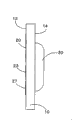
Fig. 2 is the end view of circuit board shown in Figure 1;
Fig. 3 is the schematic diagram that contacts with the printer contact pilotage according to terminal on first embodiment circuit board;
Fig. 4 is the block diagram of arranging according to the board circuit of first embodiment;
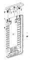
Fig. 5 is the perspective view that has the common shape of the print cartridge of circuit board among first embodiment;
Fig. 6 is the enlarged drawing of Fig. 4 circuit board support part;
Fig. 7 is mounted in the schematic diagram of the print cartridge in the printer;
Fig. 8 is the schematic diagram of arranging according to the typical circuit board terminal of second embodiment;
Fig. 9 is the schematic diagram of arranging according to the typical circuit board terminal of the 3rd embodiment;
Figure 10 is the schematic diagram of arranging according to the typical circuit board terminal of the 4th embodiment;
Figure 11 is the perspective view that is positioned at the print cartridge of type on the carriage that has the circuit board among first embodiment;
Figure 12 is the schematic diagram that the traditional circuit board terminal is arranged.
Embodiment
With reference to accompanying drawing, be described by preferred embodiment following order, can more fully understand board terminal in a circuit according to the invention.
A. arrange according to the terminal of the typical circuit board of first embodiment;
B. according to the circuit arrangement of the typical circuit board of first embodiment;
C. comprise according to the typical print cartridge of first embodiment circuit board and arranging;
D. other embodiment.
A. arrange according to the terminal of the typical circuit board of first embodiment.
Following description is to arrange according to the terminal of the circuit board of first embodiment with reference to Fig. 1-3.Fig. 1 arranges schematic diagram according to the terminal of the typical circuit board of first embodiment.Fig. 2 is the end view of circuit board shown in Figure 1.Fig. 3 is the schematic diagram that contacts with the printer contact pilotage according to terminal on first embodiment circuit board.
Being provided with on the first half on circuit board 10 and printer surface 13 arranged side by side is circular test terminal 20 basically, is used for when test memory device 30 when factory delivers.Providing in the latter half is a plurality of terminal 21-27 of rectangle basically, is arranged in two row, just in the uplink and downlink.Terminal in up is used for the I/O terminal 21 of data I/O from the left side of Fig. 1, is used to the chip select terminal 23 of chip select signal (selection signal) CS that the power terminal 22 of power is provided and is used to import selective activation storage device 30.Terminal in descending is from the left side of Fig. 1, comprise grounding terminals 24, be used for read/write terminal 25, be used for clock terminal 26 and grounding terminals 27 to storage device 30 input clock control signal CLK (synchronizing signal) to storage device 30 input read W/R.
As can be seen from Figure 1, in the circuit board 10 according to present embodiment, grounding terminals 24,27 is positioned at the two ends of the bottom line of two row terminals, and other terminal 21-23,25,26 is positioned at the inside of grounding terminals 24,27 simultaneously.Clock terminal 26 is between grounding terminals 24,27. Grounding terminals 24,27 is arranged in the row different with power terminal 22, in spatial relationship, near these terminals with power terminal 22 near the gap be not beeline.That is to say that grounding terminals 24,27 is not the terminal nearest apart from power terminal 22.In the present embodiment, " ground connection " refers to electrical reference signal and presses, and can be plus or minus voltage.
In the present embodiment, circuit board 10 has 11.9 millimeters high, the size of 7.5 mm wides, 0.71 millimeters thick.The size of terminal 21-27 is 1.8 millimeters high and 1.0 mm wides.But these terminals only are exemplary, and for example may have ± 0.5 millimeter difference.Gap between the adjacent end, for example the distance between I/O terminal 21 and the power terminal 22 approximately is 1 millimeter.For example, the gap between the terminal also can have ± 0.5 millimeter difference.
Illustrate that below with reference to Fig. 3 the terminal on the circuit board 10 contacts with the printer contact pilotage.Printer comprises the corresponding contact pilotage P1-P7 with terminal 21-27; When print cartridge was installed on the holder part of printer, terminal began to contact with contact pilotage P1-P7, therefore provided power from printer to the storage device 30 of circuit board 10, and can finish the exchanges data between printer and the circuit board 10.
In addition, because grounding terminals 24,27 is not the terminal nearest apart from power terminal 22, just can prevent the short circuit between power terminal 22 and the grounding terminals 24,27.
B. arrange according to the typical board circuit of first embodiment.
Be to arrange according to the typical board circuit of first embodiment below with reference to Fig. 4 explanation.Fig. 4 is the block diagram that brief description is arranged according to the board circuit of first embodiment.
As mentioned above, circuit board 10 comprises the storage device 30 that is positioned on the surface 13 that is connected with print cartridge.Storage device 30 in the present embodiment is electricallyerasable ROM (EEROM) (EEPROM), comprising: the memory cell 31 of consecutive access; Read/write controller 32 is used to control back and forth the read/write operation from memory cell 31; With the address counter 33 that is used to count, synchronous with clock signal clk, counting during the read/write operation between printer 100 and the memory cell 31 by read/write controller 32.
The contact pilotage P1 of printer 100 is used for back and forth from printer 100 I/O data; Contact pilotage P2 is used for providing supply voltage VDD from printer 100 to the power terminal 22 of circuit board 10.Contact pilotage P3 is used to send chip select signal CS; Contact pilotage P4 and P7 are used to provide load voltage VCC; Contact pilotage P5 is used to send read; And contact pilotage P6 is used for tranmitting data register signal CLK.
Contact pilotage P4 is connected with the box external sensed terminal of the central processing unit (CPU) of printer 100, and is connected with box external sensed power supply VCC by load resistance, thereby has the current potential that equates with box external voltage VCC.Contact pilotage P7 ground connection and have the current potential that equates with earthed voltage VSS in printer 100.
C. comprise according to the typical print cartridge of the circuit board among first embodiment and arranging.
Arrange below with reference to the typical print cartridge that circuit board 10 is installed above Fig. 5-7 explanation.Fig. 5 is the perspective view that has the print cartridge of the circuit board 10 among first embodiment.Fig. 6 is the enlarged drawing of circuit board 10 holder part among Fig. 4.Fig. 7 describes the schematic diagram that is installed in the print cartridge in the printer.
As shown in Figure 5, circuit board 10 relies on through hole 11 and groove 12 location, and is fixed on the circuit board support part 41 of print cartridge 40.
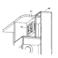
When in printer, print cartridge 40 being installed, the targeting part of print cartridge 40 leads to the guide pin on the printer 101, so that circuit board support part 41, ink-feeding hole 42, air admission hole 43 suitably contact/are connected with contact pilotage 102, ink-feeding hole 103 and air admission hole 104 on the printer.
Below with reference to Fig. 4, the step of being carried out by printer 100 is described when print cartridge 40 is installed in the printer on circuit board 10.
Contact pilotage P7 ground connection in printer of printer 100, and contact pilotage P4 is connected to the box external sensed terminal of CPU60.When print cartridge 40 is inserted in the printer 100, the contact pilotage P1-P7 of printer 100 begins to contact with the terminal 21-27 of circuit board 10.At this moment, if contact pilotage P4, the P7 of printer 100 contact with the corresponding grounding terminals 24,27 of circuit board 10, CPU60 detects earthed voltage VSS.That is to say that when print cartridge 40 was installed, printer 100 (CPU60) detected being electrically connected of grounding terminals 24,27 of contact pilotage P4, P7 and circuit board 10, and the correct installation of definite print cartridge 40.
On the other hand, if contact pilotage P4, P7 do not have to be connected with grounding terminals 24,27 with related circuit plate 10, CPU60 just detects box external voltage VCC.That is to say that printer 100 can not detect being electrically connected of contact pilotage P4, P7 and circuit board 10 grounding terminals 24,27, and determine the incorrect print cartridge of installing.
If printer 100 detects being electrically connected of contact pilotage P4, P7 and circuit board 10 grounding terminals 24,27, and the correct installation of definite print cartridge, POWER VD D just offers power terminal 22, and chip select signal CS is sent to storage device to be visited 30.
In case receive chip select signal CS, storage device 30 just activates and waits the control signal from printer 100.Data of being stored in the printer 100 beginning read storage devices 30 for example be input to clock terminal 26 corresponding to the clock signal clk of desired address in the memory cell 31, and the read W/R of indication read operation are input to read/write terminal 25.
The clock signal clk that is input to clock terminal 26 is input to address counter 33, when count counter 33 pairs of addresses in address, synchronous at this with input clock signal, the address in the indication memory cell 31.32 couples of read W/R that imported via read/write terminal 25 import and analyze by the read/write controller.In response to the reading order after analyzing, the address reading data of read/write controller 32 from the indicated memory cell 31 of address counter 33, and by I/O terminal 21 to printer 100 dateouts.
As mentioned above, the circuit board 10 of first embodiment has the grounding terminals 24,27 that is positioned at both sides, they are subjected to the influence of terminal contact pilotage contact fault basically easily, therefore reduce or eliminate when other terminal 21-23,25,26 not respectively with contact pilotage P1-P3, P5, when P6 contacts, printer detects the possibility that grounding terminals 24,27 contacts with grounding terminals contact pilotage P4, P7.The result is accurately to detect the installation of print cartridge.Although can avoid detecting the installation of print cartridge in addition and problem that can not access to storage device 30.
Usually, the ratio of the width dimensions of circuit board 10 and print cartridge 40 depth dimensionses is bigger, as in the present embodiment, during installation print cartridge a little misalignment can be easy to cause circuit board terminal and the bigger misalignment of corresponding contact pilotage, so terminal just can not contact corresponding contact pilotage.But, for the circuit board 10 of present embodiment, can be regardless of circuit board and the bigger external dimensions of print cartridge and accurately detect the installation of print cartridge.
In addition, because grounding terminals 24,27 is not the terminal nearest apart from power terminal 22, just can prevent the short circuit between power terminal 22 and the grounding terminals 24,27.Because clock terminal 26 just can stable clock signal CLK between grounding terminals 24,27.
D. other embodiment
Be with reference to the description of Fig. 8-10 below to other embodiment.Fig. 8 is the schematic diagram of arranging according to the typical circuit board terminal of second embodiment.Fig. 9 is the schematic diagram of arranging according to the typical circuit board terminal of the 3rd embodiment.Figure 10 is the schematic diagram of arranging according to the typical circuit board terminal of the 4th embodiment.When the circuit board according to second to the 4th embodiment has with according to the similar arrangement of the circuit board 10 of first embodiment the time, the element with identical function is described in detail with regard to representing and no longer need with Reference numeral specified among first embodiment.
Be with reference to the description of Fig. 8 below to second embodiment.Being provided with on the first half on surface 13 side by side according to the circuit board 200 of second embodiment is circular test terminal 20 basically, is used for when test memory device 30 when factory delivers; And being provided with on the latter half on surface 13 arranged side by side is a plurality of terminal 201-207 of rectangle basically, is arranged in two row, just in the uplink and downlink.In a plurality of rectangular terminal, terminal in up is from the left side of figure, the I/O terminal 201 that is used for the data I/O, the chip select terminal 203 that is used to provide the power terminal 202 of power and is used to import the chip select signal that activates storage device 30 selectively.Terminal in descending is from the left side of figure, and grounding terminals 204 is used for the read/write terminal 205 to storage device 30 input read, is used for clock terminal 206 and grounding terminals 207 to storage device 30 input clock signals (synchronizing signal).
As can be seen from Figure 8, in the circuit board 200 according to present embodiment, grounding terminals 204,207 is positioned at its both sides.I/O terminal 201 and chip select terminal 203 are wideer than I/O terminal 21 among first embodiment and chip select terminal 23, but even now, grounding terminals 204,207 is positioned at the both sides of circuit board 100, and other terminal 202,205,206 is positioned at the inside of grounding terminals 204,207 simultaneously.Clock terminal 206 is between grounding terminals 204,207.Grounding terminals 204,207 is arranged in the row different with power terminal 202, and is not the terminal nearest apart from power terminal 202.
Therefore, by using circuit board 200, can accurately detect the installation of print cartridge according to second embodiment.Although can also avoid detecting the installation of print cartridge and situation that can not access to storage device 30.In addition, can stable clock signal CLK, and can prevent short circuit between power terminal 202 and the grounding terminals 204,207.
Be with reference to the description of Fig. 9 below to the 3rd embodiment.Being provided with on the first half on surface 13 side by side according to the circuit board 300 of the 3rd embodiment is circular test terminal 20 basically, is used for when test memory device 30 when factory delivers; And on the latter half on surface 13 arranged side by side, be provided with a plurality of rounded termination 301-306, random alignment.Rounded termination is from the left side of figure, grounding terminals 301, be used for read/write terminal 302 to storage device 30 input read, be used for clock terminal 303 to storage device 30 input clock signals (synchronizing signal), be used to provide the power terminal 304 of power, the I/O terminal 305 and the grounding terminals 306 that are used for the data I/O.
As can be seen from Figure 9, in the circuit board 300 according to present embodiment, grounding terminals 301,306 is positioned at its both sides, and other terminal 302-305 is positioned at the inside of grounding terminals 301,306 simultaneously.Grounding terminals 301,306 is not the terminal nearest apart from power terminal 304.
Therefore, by using circuit board 300, can accurately detect the installation of print cartridge according to the 3rd embodiment.Although can also avoid detecting the installation of print cartridge and situation that can not access to storage device 30.In addition, can prevent short circuit between power terminal 304 and the grounding terminals 301,306.
Be with reference to the description of Figure 10 below to the 4th embodiment.Being provided with on the first half on surface 13 side by side according to the circuit board 400 of the 4th embodiment is circular test terminal 20 basically, is used for when test memory device 30 when factory delivers; And being provided with on the latter half on surface 13 arranged side by side is a plurality of terminal 401-407 of rectangle basically, is arranged in single file.The terminal of substantial rectangular is from the left side of figure, grounding terminals 401, be used for read/write terminal 402 to storage device 30 input read, be used for clock terminal 403 to storage device 30 input clock signals (synchronizing signal), be used to provide the power terminal 404 of power, the I/O terminal 405 that is used for the data I/O is used to import the chip select terminal 406 and the grounding terminals 407 of chip select signal.
As can be seen from Figure 10, in the circuit board 400 according to present embodiment, grounding terminals 401,407 is positioned at the both sides of its outermost, and other terminal 402-406 is positioned at the inside of grounding terminals 401,407 simultaneously.Grounding terminals 401,407 is not the terminal nearest apart from power terminal 404.
Therefore, by using circuit board 400, can accurately detect the installation of print cartridge according to the 4th embodiment.Although can also avoid detecting the installation of print cartridge and situation that can not access to storage device 30.In addition, can prevent short circuit between power terminal 404 and the grounding terminals 401,407.
Although above described circuit board herein with reference to specific preferred embodiment, these only are in order to help the understanding of the present invention, rather than limit it.Be understood that in claim institute restricted portion and can make multiple modification and improvement, and the present invention includes these distortion.
For example, in first embodiment, described circuit board 10 is mounted in according to the print cartridge 40 that is used for " disengaging carriage " type printer, but as shown in figure 11, it can be installed in the print cartridge 48 that is used for " at carriage " type printer.In this case, by using circuit board 10,200,300 or 400, can accurately detect the installation of print cartridge according to first to the 4th embodiment.Although and can avoid detecting the installation of print cartridge and situation that can not access to storage device 30.
The arrangement of the terminal described in the previous embodiment only is exemplary, grounding terminals is arranged on the both sides of circuit board.Perhaps, when terminal was arranged in the multirow, they can be positioned at the outermost end of delegation.Just realization working effect of the present invention under the collateral condition of this arrangement can provided.
But in first embodiment, circuit board 10 is installed on the print cartridge 40, and circuit board 10 can be installed on the toner Cartridge.Installation on the toner Cartridge has with print cartridge installs similar problem, and these problems can solve by circuit board 10.
But in first embodiment, the pass of the width dimensions of the depth dimensions of print cartridge 40 and circuit board 10 is 15: 1, but does not have both ratios are limited to this.For example, can use 10: 1 to 30: 1 exemplary value.In arbitrary situation,, just can realize work effect of the present invention as long as the depth dimensions of print cartridge 40 enough makes the inappropriate installation obstruction of print cartridge 40 contact with the suitable of circuit board 10 greatly with the width dimensions of circuit board 10.
Claims (14)
1. circuit board that has storage device, described storage device is used to store the data relevant with the franking material, and described circuit board comprises:
At least two grounding terminals are arranged in the both sides on the axle that is positioned at circuit board of described circuit board; With
Be arranged in a plurality of terminals on the described circuit board, be used for the described data relevant with the franking material are carried out read/write operation, wherein said a plurality of terminal comprises power terminal and control signal terminal, and described a plurality of terminal and described grounding terminals are lined up single file, and described at least two grounding terminals are not nearest terminal of the described power terminal of distance and the outermost end that is positioned at described row.
2. circuit board that has storage device, described storage device is used to store the data relevant with the franking material, and described circuit board comprises:
At least two grounding terminals are arranged in the both sides on the axle that is positioned at circuit board of described circuit board; With
Be arranged in a plurality of terminals on the described circuit board, be used for the described data relevant with the franking material are carried out read/write operation, wherein said a plurality of terminal comprises power terminal and control signal terminal, and described a plurality of terminal and described grounding terminals are aligned to multirow, and described at least two grounding terminals are not nearest terminal of the described power terminal of distance and the outermost end that is positioned at one of described multirow.
3. circuit board according to claim 2, wherein said a plurality of terminals comprise clock signal terminal, between described clock signal terminal two in described at least two grounding terminals.
4. circuit board according to claim 2, wherein said a plurality of terminals comprise power terminal, two outermost end that are positioned at delegation in described at least two grounding terminals, this row is different from the row that comprises described power terminal.
5. circuit board according to claim 2, wherein said a plurality of terminals comprise data I/O terminal, power terminal is selected Signal Terminal, read terminal and clock signal terminal, and wherein said multirow comprises:
First the row, wherein said data I/O terminal and described selection Signal Terminal be positioned at described power terminal both sides and
Second the row, wherein said read terminal and described clock signal terminal between described two grounding terminals,
Described first row is than the centralized positioning of the more approaching described circuit board of described second row, and the described terminal in described terminal in described first row and described second row is arranged in the mode that replaces.
6. according to any one described circuit board in the claim 1 to 5, wherein said a plurality of terminals are arranged by the direction that described each row forms with the interval of 1mm.
7. one kind is configured to the marker material container that uses with printing equipment, comprises
The vessel that is used for the described marker material of splendid attire; With
Circuit board with storage device, described storage device is used for storing the data relevant with the marker material that is contained in described vessel, described circuit board has a plurality of terminals of arranging thereon, at least two grounding terminals with both sides on the axle that is positioned at described circuit board that is arranged in described circuit board, wherein said a plurality of terminal and described grounding terminals are arranged in the single file, and two grounding terminals in described at least two grounding terminals are not nearest terminal of the described power terminal of distance and the outermost end that is positioned at described row.
8. one kind is configured to the marker material container that uses with printing equipment, comprising:
The vessel that is used for the described marker material of splendid attire; With
Circuit board with storage device, described storage device is used for storing the data relevant with the marker material that is contained in described vessel, described circuit board has at least two grounding terminals on the both sides on the axle that is positioned at described circuit board, and a plurality of terminals of on described circuit board, arranging, wherein said a plurality of terminal and described grounding terminals are arranged in multirow, and two grounding terminals in described at least two grounding terminals are not the nearest terminals of the described power terminal of distance and are positioned at the wherein outermost end of delegation of described multirow.
9. marker material container according to claim 8, wherein said a plurality of terminal comprises power terminal, the control signal terminal, and clock signal terminal, two outermost end that are positioned at certain delegation in described at least two grounding terminals of while, this row is different from the row that comprises described power terminal, and in the row identical with described clock signal terminal.
10. marker material container according to claim 8, wherein said a plurality of terminals comprise data I/O terminal, power terminal is selected Signal Terminal, read terminal and clock signal terminal, and wherein said multirow comprises:
First the row, wherein said data I/O terminal and described selection Signal Terminal be positioned at described power terminal both sides and
Second the row, wherein said read terminal and described clock signal terminal between described two grounding terminals,
Described first row is than the centralized positioning of the more approaching described circuit board of described second row, and the described terminal in described terminal in described first row and described second row is arranged in the mode that replaces.
11. according to any one described marker material container in the claim 7 to 10, wherein said a plurality of terminals are arranged by the direction that described each row forms with the interval of 1mm.
12. according to any one described marker material container in the claim 7 to 10, wherein said marker material container is a print cartridge.
13. according to any one described marker material container in the claim 7 to 10, wherein said marker material container is a toner Cartridge.
14. according to any one described marker material container in the claim 7 to 10,
One connects the surface, has two ends and is constructed to be connected to this printing device, wherein should connection surperficial comprise a marker material that is positioned at this connection centre of surface place present opening and
Wherein this circuit board is positioned at arbitrary end on this connection surface.
Applications Claiming Priority (2)
| Application Number | Priority Date | Filing Date | Title |
|---|---|---|---|
| JP395925/00 | 2000-12-26 | ||
| JP2000395925A JP3649123B2 (en) | 2000-12-26 | 2000-12-26 | Circuit board terminals |
Related Child Applications (2)
| Application Number | Title | Priority Date | Filing Date |
|---|---|---|---|
| CN2008101445219A Division CN101342817B (en) | 2000-12-26 | 2001-12-26 | Circuit board |
| CNB2006100592692A Division CN100461532C (en) | 2000-12-26 | 2001-12-26 | Terminals for circuit board |
Publications (2)
| Publication Number | Publication Date |
|---|---|
| CN1362757A CN1362757A (en) | 2002-08-07 |
| CN100477385C true CN100477385C (en) | 2009-04-08 |
Family
ID=18861302
Family Applications (3)
| Application Number | Title | Priority Date | Filing Date |
|---|---|---|---|
| CNB011432942A Expired - Lifetime CN100477385C (en) | 2000-12-26 | 2001-12-26 | Circuit board terminal |
| CNB2006100592692A Expired - Fee Related CN100461532C (en) | 2000-12-26 | 2001-12-26 | Terminals for circuit board |
| CN2008101445219A Expired - Lifetime CN101342817B (en) | 2000-12-26 | 2001-12-26 | Circuit board |
Family Applications After (2)
| Application Number | Title | Priority Date | Filing Date |
|---|---|---|---|
| CNB2006100592692A Expired - Fee Related CN100461532C (en) | 2000-12-26 | 2001-12-26 | Terminals for circuit board |
| CN2008101445219A Expired - Lifetime CN101342817B (en) | 2000-12-26 | 2001-12-26 | Circuit board |
Country Status (10)
| Country | Link |
|---|---|
| US (2) | US6648445B2 (en) |
| EP (3) | EP1219437B2 (en) |
| JP (1) | JP3649123B2 (en) |
| CN (3) | CN100477385C (en) |
| AT (2) | ATE409121T1 (en) |
| DE (2) | DE60135935D1 (en) |
| DK (2) | DK1219437T4 (en) |
| ES (2) | ES2248219T5 (en) |
| HK (3) | HK1047909B (en) |
| PT (2) | PT1219437E (en) |
Families Citing this family (75)
| Publication number | Priority date | Publication date | Assignee | Title |
|---|---|---|---|---|
| JP3649123B2 (en) * | 2000-12-26 | 2005-05-18 | セイコーエプソン株式会社 | Circuit board terminals |
| US7101021B2 (en) | 2001-07-30 | 2006-09-05 | Seiko Epson Corporation | Connection apparatus for circuit board, ink jet type recording apparatus using the same, IC chip and ink cartridge having IC chip |
| JP3666491B2 (en) * | 2002-03-29 | 2005-06-29 | セイコーエプソン株式会社 | Ink cartridge and recording apparatus |
| US7239413B2 (en) * | 2002-10-29 | 2007-07-03 | Hewlett-Packard Development Company, L.P. | Printer replaceable component |
| DE10307030A1 (en) * | 2003-02-20 | 2004-09-09 | Eppendorf Ag | dosing |
| JP4529560B2 (en) * | 2004-01-30 | 2010-08-25 | セイコーエプソン株式会社 | Liquid container |
| JP4529125B2 (en) * | 2003-08-08 | 2010-08-25 | セイコーエプソン株式会社 | Liquid container |
| MXPA04012988A (en) | 2003-12-22 | 2005-10-18 | Seiko Epson Corp | Ink cartridge attachment/detachment device, recording apparatus, liquid ejection apparatus, and liquid container. |
| JP2005331703A (en) * | 2004-05-20 | 2005-12-02 | Konica Minolta Business Technologies Inc | Image forming apparatus |
| CN100496980C (en) | 2004-06-02 | 2009-06-10 | 佳能株式会社 | Head substrate, recording head, head cartridge, and recorder |
| JP4631850B2 (en) * | 2004-09-01 | 2011-02-16 | セイコーエプソン株式会社 | Printing material container and printing apparatus |
| US20080170110A1 (en) * | 2004-11-17 | 2008-07-17 | Nu-Kote International, Inc. | Circuit board with terminals arranged in a single row and disposed at board edges, cartridges with the circuit board, and methods for making same |
| KR100584611B1 (en) * | 2004-11-27 | 2006-06-01 | 삼성전자주식회사 | Inkjet printer |
| EP2769850A3 (en) | 2004-11-30 | 2016-04-13 | Panduit Corporation | Market-based labeling systems and method |
| WO2006104267A1 (en) * | 2005-03-31 | 2006-10-05 | Seiko Epson Corporation | Liquid container and circuit board for liquid container |
| JP4726195B2 (en) * | 2005-04-14 | 2011-07-20 | キヤノン株式会社 | Liquid discharge recording head and liquid discharge recording apparatus including the same |
| JP4352019B2 (en) * | 2005-04-22 | 2009-10-28 | キヤノン株式会社 | Ink jet recording head and ink jet recording apparatus using the head |
| WO2007003908A1 (en) * | 2005-06-30 | 2007-01-11 | Dynamic Cassette International Ltd. | An ink cartridge and a memory device |
| JP5055868B2 (en) * | 2005-08-17 | 2012-10-24 | セイコーエプソン株式会社 | Liquid container |
| JP5055867B2 (en) * | 2005-08-17 | 2012-10-24 | セイコーエプソン株式会社 | Liquid container |
| JP2007165048A (en) * | 2005-12-12 | 2007-06-28 | Smc Corp | Signal input/output device |
| AU2011100738B4 (en) * | 2005-12-26 | 2012-10-11 | Seiko Epson Corporation | Printing Material Container |
| AU2013200733B2 (en) * | 2005-12-26 | 2013-08-22 | Seiko Epson Corporation | Ink cartridge, ink supply system and circuit board |
| AU2011100735B4 (en) * | 2005-12-26 | 2012-10-11 | Seiko Epson Corporation | Ink Cartridge |
| AU2011100736B4 (en) * | 2005-12-26 | 2012-03-01 | Seiko Epson Corporation | Printing material container |
| UA108344C2 (en) * | 2005-12-26 | 2015-04-27 | PRINTING MATERIAL CONTAINER AND BOARD TO BE INSTALLED ON PRINTING MATERIAL | |
| AU2013202185B2 (en) * | 2005-12-26 | 2013-09-12 | Seiko Epson Corporation | Ink cartridge |
| AU2011100737B4 (en) * | 2005-12-26 | 2012-06-14 | Seiko Epson Corporation | Printing material container |
| JP4144637B2 (en) * | 2005-12-26 | 2008-09-03 | セイコーエプソン株式会社 | Printing material container, substrate, printing apparatus, and method for preparing printing material container |
| DE102006017045A1 (en) * | 2006-04-11 | 2007-04-19 | 3T Supplies Ag | Ink cartridge for printer, has contact element such that at least one contact of printer device is brought opposite to counter contact device whereby contact element is movably arranged relative to side of ink cartridge |
| JP5610768B2 (en) | 2006-10-31 | 2014-10-22 | センシエント・カラーズ・インコーポレーテッド | Modified pigment and method of making and using it |
| JP5086698B2 (en) * | 2007-06-04 | 2012-11-28 | キヤノン株式会社 | Element substrate, recording head, and recording apparatus |
| CN201064977Y (en) * | 2007-08-10 | 2008-05-28 | 珠海天威技术开发有限公司 | Chip and ink box using the same |
| WO2009026552A2 (en) | 2007-08-23 | 2009-02-26 | Sensient Colors Inc. | Self-dispersed pigments and methods for making and using the same |
| CN101434147B (en) * | 2007-11-12 | 2010-09-15 | 研能科技股份有限公司 | Bearing device for ink cartridge of printer |
| DE102008009460A1 (en) * | 2008-02-15 | 2009-08-20 | Pelikan Hardcopy Production Ag | Ink cartridge with printed circuit board element |
| JP5206506B2 (en) * | 2008-03-13 | 2013-06-12 | セイコーエプソン株式会社 | Mounting device, substrate, and method for changing liquid information |
| JP5083250B2 (en) | 2008-03-13 | 2012-11-28 | セイコーエプソン株式会社 | How to change liquid container, substrate, liquid information |
| JP5141606B2 (en) * | 2008-03-26 | 2013-02-13 | セイコーエプソン株式会社 | Printing device |
| JP5387107B2 (en) * | 2008-04-17 | 2014-01-15 | セイコーエプソン株式会社 | Liquid ejector |
| JP2010111116A (en) * | 2008-10-09 | 2010-05-20 | Seiko Epson Corp | Circuit board and liquid supplying unit |
| CA2757928A1 (en) | 2009-04-07 | 2010-10-14 | Sensient Colors Inc. | Self-dispersing particles and methods for making and using the same |
| US8540347B2 (en) | 2009-05-15 | 2013-09-24 | Seiko Epson Corporation | Recording material delivery system for recording material-consuming apparatus; circuit board; structural body; and ink cartridge |
| SG10201903208SA (en) | 2010-06-11 | 2019-05-30 | Ricoh Co Ltd | Information storage device, removable device, developer container, and image forming apparatus |
| JP5750849B2 (en) | 2010-09-03 | 2015-07-22 | セイコーエプソン株式会社 | Printing device, cartridge set, and adapter set |
| JP5776385B2 (en) | 2010-09-03 | 2015-09-09 | セイコーエプソン株式会社 | Printing device |
| US8764172B2 (en) | 2010-09-03 | 2014-07-01 | Seiko Epson Corporation | Printing apparatus, printing material cartridge, adaptor for printing material container, and circuit board |
| JP5630157B2 (en) | 2010-09-03 | 2014-11-26 | セイコーエプソン株式会社 | Printing device |
| US8556385B2 (en) | 2010-09-09 | 2013-10-15 | Statis Control Components, Inc. | Systems and methods for imaging components having a single row of contact pads |
| JP5541029B2 (en) * | 2010-09-16 | 2014-07-09 | セイコーエプソン株式会社 | Printing device, printing material cartridge, circuit board and adapter |
| JP5541030B2 (en) * | 2010-09-16 | 2014-07-09 | セイコーエプソン株式会社 | Printing device, printing material cartridge, circuit board and adapter |
| US8651643B2 (en) | 2010-10-22 | 2014-02-18 | Hewlett-Packard Development Company, L.P. | Fluid cartridge |
| JP5810643B2 (en) * | 2011-06-06 | 2015-11-11 | セイコーエプソン株式会社 | Printing device |
| JP5922918B2 (en) * | 2011-12-05 | 2016-05-24 | キヤノン株式会社 | Semiconductor device for liquid discharge head, liquid discharge head, and liquid discharge device |
| JP2012071615A (en) * | 2011-12-07 | 2012-04-12 | Seiko Epson Corp | Circuit board |
| JP5998495B2 (en) * | 2012-02-01 | 2016-09-28 | セイコーエプソン株式会社 | Circuit board, printing material container, and printing apparatus |
| JP5998494B2 (en) * | 2012-02-01 | 2016-09-28 | セイコーエプソン株式会社 | Circuit board, printing material container, and printing apparatus |
| CN203004521U (en) * | 2012-12-17 | 2013-06-19 | 珠海艾派克微电子有限公司 | Ink box chip used for printer and ink box comprising the chip |
| CN103101317B (en) * | 2012-12-17 | 2015-09-30 | 珠海艾派克微电子有限公司 | A kind of ink box chip on printer and comprise the print cartridge of this chip |
| CN104163043B (en) | 2013-05-17 | 2016-08-24 | 珠海纳思达企业管理有限公司 | Ink box chip, print cartridge and structure |
| CN104175721B (en) * | 2013-05-22 | 2016-09-28 | 珠海艾派克微电子有限公司 | Ink box chip method for detecting short circuit, chip, print cartridge and recording equipment |
| CN104378913B (en) * | 2013-08-17 | 2017-10-13 | 珠海艾派克微电子有限公司 | Circuit substrate, storage chip and imaging cartridge |
| CN103707648B (en) * | 2013-12-25 | 2016-08-24 | 珠海天威飞马打印耗材有限公司 | Ink box chip, print cartridge and ink-jet printer |
| CN103753962B (en) * | 2013-12-26 | 2016-06-22 | 珠海艾派克微电子有限公司 | A kind of imaging cartridge, imaging box chip and short circuit bypassing method thereof |
| CN104260555B (en) * | 2014-09-25 | 2016-09-21 | 珠海天威飞马打印耗材有限公司 | Consumable chip and consumable container |
| CN104354473B (en) * | 2014-09-29 | 2016-03-30 | 珠海艾派克微电子有限公司 | A kind of imaging box chip and imaging cartridge |
| JP2016206320A (en) * | 2015-04-20 | 2016-12-08 | シャープ株式会社 | Image forming apparatus |
| JP6512177B2 (en) * | 2016-06-08 | 2019-05-15 | 京セラドキュメントソリューションズ株式会社 | Image forming apparatus provided with toner container |
| CN106527081B (en) * | 2016-08-10 | 2023-06-06 | 江西亿铂电子科技有限公司 | Developing box |
| WO2018113706A1 (en) * | 2016-12-20 | 2018-06-28 | 珠海艾派克微电子有限公司 | Electronic chip used together with circuit board belonging to imaging cartridge, and imaging cartridge and method for restoring imaging cartridge |
| JP7035714B2 (en) * | 2018-03-29 | 2022-03-15 | ブラザー工業株式会社 | Liquid cartridges and systems |
| US11163245B2 (en) | 2018-04-30 | 2021-11-02 | Hewlett-Packard Development Company, L.P. | Embedded memory resources |
| CN110783725A (en) * | 2018-07-24 | 2020-02-11 | 富士康(昆山)电脑接插件有限公司 | Grounding buckle, circuit board assembly provided with grounding buckle and manufacturing method of circuit board assembly |
| CN113467009B (en) * | 2020-03-31 | 2022-08-26 | 华为技术有限公司 | Optical module and network equipment |
| US11535037B1 (en) | 2021-12-28 | 2022-12-27 | Seiko Epson Corporation | Device, board, liquid accommodation container, and printing system |
Family Cites Families (24)
| Publication number | Priority date | Publication date | Assignee | Title |
|---|---|---|---|---|
| US603942A (en) † | 1898-05-10 | Eugelst clarenbach | ||
| ES2252908T3 (en) * | 1989-08-05 | 2006-05-16 | Canon Kabushiki Kaisha | PRINTING DEVICE FOR INK JETS AND INK CARTRIDGE FOR THE APPLIANCE. |
| US5363134A (en) * | 1992-05-20 | 1994-11-08 | Hewlett-Packard Corporation | Integrated circuit printhead for an ink jet printer including an integrated identification circuit |
| US5411343A (en) * | 1992-07-31 | 1995-05-02 | Hewlett-Packard Company | Redundant make/break interconnect for a print head |
| US5471163A (en) † | 1993-11-16 | 1995-11-28 | Hewlett-Packard Company | Tab circuit fusible links for disconnection or encoding information |
| US5610635A (en) * | 1994-08-09 | 1997-03-11 | Encad, Inc. | Printer ink cartridge with memory storage capacity |
| US5646660A (en) * | 1994-08-09 | 1997-07-08 | Encad, Inc. | Printer ink cartridge with drive logic integrated circuit |
| AU3241795A (en) * | 1994-08-09 | 1996-03-07 | Encad, Inc. | Printer ink cartridge |
| DE69514617T2 (en) * | 1994-11-02 | 2000-09-21 | Seiko Epson Corp | Ink jet recorders and associated printer |
| US5748179A (en) * | 1995-05-15 | 1998-05-05 | Hitachi, Ltd. | LCD device having driving circuits with multilayer external terminals |
| US6102517A (en) * | 1995-12-25 | 2000-08-15 | Seiko Epson Corporation | Ink-jet recording apparatus for ink cartridge |
| JPH09205283A (en) * | 1996-01-25 | 1997-08-05 | Hitachi Ltd | Semiconductor module and memory module |
| US5772448A (en) * | 1996-04-02 | 1998-06-30 | Compaq Computer Corporation | Edgecard circuit board |
| JPH10119314A (en) * | 1996-08-30 | 1998-05-12 | Canon Inc | Method for connecting liquid discharge head unit, the head unit, and liquid discharge cartridge |
| US6168262B1 (en) * | 1997-01-30 | 2001-01-02 | Hewlett-Packard Company | Electrical interconnect for replaceable ink containers |
| US5865631A (en) * | 1997-04-10 | 1999-02-02 | International Business Machines Corporation | Method for reducing shorts on a printed circuit board edge connector |
| US6227643B1 (en) * | 1997-05-20 | 2001-05-08 | Encad, Inc. | Intelligent printer components and printing system |
| US6000733A (en) * | 1997-09-25 | 1999-12-14 | International Door Closers, Inc. | Presser bar mechanism |
| US6575548B1 (en) * | 1997-10-28 | 2003-06-10 | Hewlett-Packard Company | System and method for controlling energy characteristics of an inkjet printhead |
| US6039428A (en) * | 1998-05-13 | 2000-03-21 | Hewlett-Packard Company | Method for improving ink jet printer reliability in the presence of ink shorts |
| EP2179848A1 (en) * | 1998-05-18 | 2010-04-28 | Seiko Epson Corporation | Ink-jet printing apparatus and ink cartridge therefor |
| US6161915A (en) * | 1998-06-19 | 2000-12-19 | Lexmark International, Inc | Identification of thermal inkjet printer cartridges |
| US7110127B2 (en) * | 1999-04-20 | 2006-09-19 | Hewlett-Packard Development Company, L.P. | Method and apparatus for product regionalization |
| JP3649123B2 (en) * | 2000-12-26 | 2005-05-18 | セイコーエプソン株式会社 | Circuit board terminals |
-
2000
- 2000-12-26 JP JP2000395925A patent/JP3649123B2/en not_active Expired - Fee Related
-
2001
- 2001-12-19 DE DE60135935T patent/DE60135935D1/en not_active Expired - Lifetime
- 2001-12-19 DK DK01130240T patent/DK1219437T4/en active
- 2001-12-19 PT PT01130240T patent/PT1219437E/en unknown
- 2001-12-19 AT AT05018578T patent/ATE409121T1/en active
- 2001-12-19 PT PT05018578T patent/PT1598198E/en unknown
- 2001-12-19 EP EP01130240A patent/EP1219437B2/en not_active Expired - Lifetime
- 2001-12-19 ES ES01130240T patent/ES2248219T5/en not_active Expired - Lifetime
- 2001-12-19 DK DK05018578T patent/DK1598198T3/en active
- 2001-12-19 AT AT01130240T patent/ATE303897T1/en active
- 2001-12-19 EP EP05018578A patent/EP1598198B1/en not_active Expired - Lifetime
- 2001-12-19 EP EP08015764A patent/EP1992491A3/en not_active Withdrawn
- 2001-12-19 DE DE60113227T patent/DE60113227T3/en not_active Expired - Lifetime
- 2001-12-19 US US10/028,474 patent/US6648445B2/en not_active Expired - Lifetime
- 2001-12-19 ES ES05018578T patent/ES2313168T3/en not_active Expired - Lifetime
- 2001-12-26 CN CNB011432942A patent/CN100477385C/en not_active Expired - Lifetime
- 2001-12-26 CN CNB2006100592692A patent/CN100461532C/en not_active Expired - Fee Related
- 2001-12-26 CN CN2008101445219A patent/CN101342817B/en not_active Expired - Lifetime
-
2002
- 2002-12-30 HK HK02109423.6A patent/HK1047909B/en not_active IP Right Cessation
-
2003
- 2003-08-05 US US10/634,428 patent/US7125100B2/en not_active Expired - Lifetime
-
2006
- 2006-03-15 HK HK06103337.0A patent/HK1083479A1/en not_active IP Right Cessation
-
2009
- 2009-04-14 HK HK09103414.3A patent/HK1125340A1/en not_active IP Right Cessation
Also Published As
Similar Documents
| Publication | Publication Date | Title |
|---|---|---|
| CN100477385C (en) | Circuit board terminal | |
| CN101712238B (en) | Printing material container and circuit board equipped thereon | |
| CN102381031B (en) | Printing apparatus | |
| CN107901611B (en) | Chip and ink box | |
| JP2002198627A5 (en) | ||
| ZA200806989B (en) | Printing material housing device | |
| JP3948470B2 (en) | Circuit board terminals | |
| BRPI0814732B1 (en) | PRINTER | |
| CN110991593A (en) | Orientation independent method for handoff with Xerox printed memory labels | |
| US6546619B1 (en) | Electronic device mounting system and method | |
| CN102815104A (en) | Printing apparatus | |
| JP4232833B2 (en) | Circuit board terminals | |
| CN1874896B (en) | Fluid jet device | |
| CN204914914U (en) | Ink horn and be used for printer on ink horn chip | |
| CN111890800B (en) | Ink box chip, ink box and ink-jet printer | |
| CN211684116U (en) | Chip mounted on ink box and ink box using chip | |
| CN211892486U (en) | Ink box chip, printing ink box and ink-jet printer | |
| CN219523401U (en) | Split type circuit board and ink horn | |
| CN103152973A (en) | Circuit board | |
| CN113942313B (en) | Connecting piece, consumable chip, consumable container, electronic imaging device, and method for mounting connecting piece and consumable container | |
| US20200234752A1 (en) | Method for testing a memory device |
Legal Events
| Date | Code | Title | Description |
|---|---|---|---|
| C10 | Entry into substantive examination | ||
| SE01 | Entry into force of request for substantive examination | ||
| C06 | Publication | ||
| PB01 | Publication | ||
| C14 | Grant of patent or utility model | ||
| GR01 | Patent grant | ||
| CX01 | Expiry of patent term | ||
| CX01 | Expiry of patent term |
Granted publication date: 20090408 |