CN100441639C - Color shifting carbon-containing interference pigments - Google Patents
Color shifting carbon-containing interference pigments Download PDFInfo
- Publication number
- CN100441639C CN100441639C CNB008145849A CN00814584A CN100441639C CN 100441639 C CN100441639 C CN 100441639C CN B008145849 A CNB008145849 A CN B008145849A CN 00814584 A CN00814584 A CN 00814584A CN 100441639 C CN100441639 C CN 100441639C
- Authority
- CN
- China
- Prior art keywords
- carbon
- coating
- insulation layer
- thin film
- interference thin
- Prior art date
- Legal status (The legal status is an assumption and is not a legal conclusion. Google has not performed a legal analysis and makes no representation as to the accuracy of the status listed.)
- Expired - Lifetime
Links
Images


Classifications
-
- G—PHYSICS
- G02—OPTICS
- G02B—OPTICAL ELEMENTS, SYSTEMS OR APPARATUS
- G02B5/00—Optical elements other than lenses
- G02B5/20—Filters
- G02B5/28—Interference filters
- G02B5/285—Interference filters comprising deposited thin solid films
- G02B5/287—Interference filters comprising deposited thin solid films comprising at least one layer of organic material
-
- C—CHEMISTRY; METALLURGY
- C09—DYES; PAINTS; POLISHES; NATURAL RESINS; ADHESIVES; COMPOSITIONS NOT OTHERWISE PROVIDED FOR; APPLICATIONS OF MATERIALS NOT OTHERWISE PROVIDED FOR
- C09C—TREATMENT OF INORGANIC MATERIALS, OTHER THAN FIBROUS FILLERS, TO ENHANCE THEIR PIGMENTING OR FILLING PROPERTIES ; PREPARATION OF CARBON BLACK ; PREPARATION OF INORGANIC MATERIALS WHICH ARE NO SINGLE CHEMICAL COMPOUNDS AND WHICH ARE MAINLY USED AS PIGMENTS OR FILLERS
- C09C1/00—Treatment of specific inorganic materials other than fibrous fillers; Preparation of carbon black
- C09C1/0015—Pigments exhibiting interference colours, e.g. transparent platelets of appropriate thinness or flaky substrates, e.g. mica, bearing appropriate thin transparent coatings
- C09C1/0021—Pigments exhibiting interference colours, e.g. transparent platelets of appropriate thinness or flaky substrates, e.g. mica, bearing appropriate thin transparent coatings comprising a core coated with only one layer having a high or low refractive index
-
- C—CHEMISTRY; METALLURGY
- C09—DYES; PAINTS; POLISHES; NATURAL RESINS; ADHESIVES; COMPOSITIONS NOT OTHERWISE PROVIDED FOR; APPLICATIONS OF MATERIALS NOT OTHERWISE PROVIDED FOR
- C09D—COATING COMPOSITIONS, e.g. PAINTS, VARNISHES OR LACQUERS; FILLING PASTES; CHEMICAL PAINT OR INK REMOVERS; INKS; CORRECTING FLUIDS; WOODSTAINS; PASTES OR SOLIDS FOR COLOURING OR PRINTING; USE OF MATERIALS THEREFOR
- C09D5/00—Coating compositions, e.g. paints, varnishes or lacquers, characterised by their physical nature or the effects produced; Filling pastes
- C09D5/36—Pearl essence, e.g. coatings containing platelet-like pigments for pearl lustre
-
- C—CHEMISTRY; METALLURGY
- C23—COATING METALLIC MATERIAL; COATING MATERIAL WITH METALLIC MATERIAL; CHEMICAL SURFACE TREATMENT; DIFFUSION TREATMENT OF METALLIC MATERIAL; COATING BY VACUUM EVAPORATION, BY SPUTTERING, BY ION IMPLANTATION OR BY CHEMICAL VAPOUR DEPOSITION, IN GENERAL; INHIBITING CORROSION OF METALLIC MATERIAL OR INCRUSTATION IN GENERAL
- C23C—COATING METALLIC MATERIAL; COATING MATERIAL WITH METALLIC MATERIAL; SURFACE TREATMENT OF METALLIC MATERIAL BY DIFFUSION INTO THE SURFACE, BY CHEMICAL CONVERSION OR SUBSTITUTION; COATING BY VACUUM EVAPORATION, BY SPUTTERING, BY ION IMPLANTATION OR BY CHEMICAL VAPOUR DEPOSITION, IN GENERAL
- C23C14/00—Coating by vacuum evaporation, by sputtering or by ion implantation of the coating forming material
- C23C14/0005—Separation of the coating from the substrate
-
- C—CHEMISTRY; METALLURGY
- C23—COATING METALLIC MATERIAL; COATING MATERIAL WITH METALLIC MATERIAL; CHEMICAL SURFACE TREATMENT; DIFFUSION TREATMENT OF METALLIC MATERIAL; COATING BY VACUUM EVAPORATION, BY SPUTTERING, BY ION IMPLANTATION OR BY CHEMICAL VAPOUR DEPOSITION, IN GENERAL; INHIBITING CORROSION OF METALLIC MATERIAL OR INCRUSTATION IN GENERAL
- C23C—COATING METALLIC MATERIAL; COATING MATERIAL WITH METALLIC MATERIAL; SURFACE TREATMENT OF METALLIC MATERIAL BY DIFFUSION INTO THE SURFACE, BY CHEMICAL CONVERSION OR SUBSTITUTION; COATING BY VACUUM EVAPORATION, BY SPUTTERING, BY ION IMPLANTATION OR BY CHEMICAL VAPOUR DEPOSITION, IN GENERAL
- C23C14/00—Coating by vacuum evaporation, by sputtering or by ion implantation of the coating forming material
- C23C14/0015—Coating by vacuum evaporation, by sputtering or by ion implantation of the coating forming material characterized by the colour of the layer
-
- C—CHEMISTRY; METALLURGY
- C23—COATING METALLIC MATERIAL; COATING MATERIAL WITH METALLIC MATERIAL; CHEMICAL SURFACE TREATMENT; DIFFUSION TREATMENT OF METALLIC MATERIAL; COATING BY VACUUM EVAPORATION, BY SPUTTERING, BY ION IMPLANTATION OR BY CHEMICAL VAPOUR DEPOSITION, IN GENERAL; INHIBITING CORROSION OF METALLIC MATERIAL OR INCRUSTATION IN GENERAL
- C23C—COATING METALLIC MATERIAL; COATING MATERIAL WITH METALLIC MATERIAL; SURFACE TREATMENT OF METALLIC MATERIAL BY DIFFUSION INTO THE SURFACE, BY CHEMICAL CONVERSION OR SUBSTITUTION; COATING BY VACUUM EVAPORATION, BY SPUTTERING, BY ION IMPLANTATION OR BY CHEMICAL VAPOUR DEPOSITION, IN GENERAL
- C23C16/00—Chemical coating by decomposition of gaseous compounds, without leaving reaction products of surface material in the coating, i.e. chemical vapour deposition [CVD] processes
- C23C16/006—Chemical coating by decomposition of gaseous compounds, without leaving reaction products of surface material in the coating, i.e. chemical vapour deposition [CVD] processes characterized by the colour of the layer
-
- C—CHEMISTRY; METALLURGY
- C23—COATING METALLIC MATERIAL; COATING MATERIAL WITH METALLIC MATERIAL; CHEMICAL SURFACE TREATMENT; DIFFUSION TREATMENT OF METALLIC MATERIAL; COATING BY VACUUM EVAPORATION, BY SPUTTERING, BY ION IMPLANTATION OR BY CHEMICAL VAPOUR DEPOSITION, IN GENERAL; INHIBITING CORROSION OF METALLIC MATERIAL OR INCRUSTATION IN GENERAL
- C23C—COATING METALLIC MATERIAL; COATING MATERIAL WITH METALLIC MATERIAL; SURFACE TREATMENT OF METALLIC MATERIAL BY DIFFUSION INTO THE SURFACE, BY CHEMICAL CONVERSION OR SUBSTITUTION; COATING BY VACUUM EVAPORATION, BY SPUTTERING, BY ION IMPLANTATION OR BY CHEMICAL VAPOUR DEPOSITION, IN GENERAL
- C23C16/00—Chemical coating by decomposition of gaseous compounds, without leaving reaction products of surface material in the coating, i.e. chemical vapour deposition [CVD] processes
- C23C16/01—Chemical coating by decomposition of gaseous compounds, without leaving reaction products of surface material in the coating, i.e. chemical vapour deposition [CVD] processes on temporary substrates, e.g. substrates subsequently removed by etching
-
- G—PHYSICS
- G02—OPTICS
- G02B—OPTICAL ELEMENTS, SYSTEMS OR APPARATUS
- G02B5/00—Optical elements other than lenses
- G02B5/20—Filters
- G02B5/28—Interference filters
- G02B5/285—Interference filters comprising deposited thin solid films
-
- G—PHYSICS
- G02—OPTICS
- G02B—OPTICAL ELEMENTS, SYSTEMS OR APPARATUS
- G02B5/00—Optical elements other than lenses
- G02B5/20—Filters
- G02B5/28—Interference filters
- G02B5/285—Interference filters comprising deposited thin solid films
- G02B5/286—Interference filters comprising deposited thin solid films having four or fewer layers, e.g. for achieving a colour effect
-
- C—CHEMISTRY; METALLURGY
- C01—INORGANIC CHEMISTRY
- C01P—INDEXING SCHEME RELATING TO STRUCTURAL AND PHYSICAL ASPECTS OF SOLID INORGANIC COMPOUNDS
- C01P2004/00—Particle morphology
- C01P2004/80—Particles consisting of a mixture of two or more inorganic phases
- C01P2004/82—Particles consisting of a mixture of two or more inorganic phases two phases having the same anion, e.g. both oxidic phases
- C01P2004/84—Particles consisting of a mixture of two or more inorganic phases two phases having the same anion, e.g. both oxidic phases one phase coated with the other
- C01P2004/88—Thick layer coatings
-
- C—CHEMISTRY; METALLURGY
- C09—DYES; PAINTS; POLISHES; NATURAL RESINS; ADHESIVES; COMPOSITIONS NOT OTHERWISE PROVIDED FOR; APPLICATIONS OF MATERIALS NOT OTHERWISE PROVIDED FOR
- C09C—TREATMENT OF INORGANIC MATERIALS, OTHER THAN FIBROUS FILLERS, TO ENHANCE THEIR PIGMENTING OR FILLING PROPERTIES ; PREPARATION OF CARBON BLACK ; PREPARATION OF INORGANIC MATERIALS WHICH ARE NO SINGLE CHEMICAL COMPOUNDS AND WHICH ARE MAINLY USED AS PIGMENTS OR FILLERS
- C09C2200/00—Compositional and structural details of pigments exhibiting interference colours
- C09C2200/10—Interference pigments characterized by the core material
- C09C2200/1004—Interference pigments characterized by the core material the core comprising at least one inorganic oxide, e.g. Al2O3, TiO2 or SiO2
-
- C—CHEMISTRY; METALLURGY
- C09—DYES; PAINTS; POLISHES; NATURAL RESINS; ADHESIVES; COMPOSITIONS NOT OTHERWISE PROVIDED FOR; APPLICATIONS OF MATERIALS NOT OTHERWISE PROVIDED FOR
- C09C—TREATMENT OF INORGANIC MATERIALS, OTHER THAN FIBROUS FILLERS, TO ENHANCE THEIR PIGMENTING OR FILLING PROPERTIES ; PREPARATION OF CARBON BLACK ; PREPARATION OF INORGANIC MATERIALS WHICH ARE NO SINGLE CHEMICAL COMPOUNDS AND WHICH ARE MAINLY USED AS PIGMENTS OR FILLERS
- C09C2200/00—Compositional and structural details of pigments exhibiting interference colours
- C09C2200/10—Interference pigments characterized by the core material
- C09C2200/1037—Interference pigments characterized by the core material the core consisting of an inorganic suboxide or a mixture thereof, e.g. SiOx or TiOx
-
- C—CHEMISTRY; METALLURGY
- C09—DYES; PAINTS; POLISHES; NATURAL RESINS; ADHESIVES; COMPOSITIONS NOT OTHERWISE PROVIDED FOR; APPLICATIONS OF MATERIALS NOT OTHERWISE PROVIDED FOR
- C09C—TREATMENT OF INORGANIC MATERIALS, OTHER THAN FIBROUS FILLERS, TO ENHANCE THEIR PIGMENTING OR FILLING PROPERTIES ; PREPARATION OF CARBON BLACK ; PREPARATION OF INORGANIC MATERIALS WHICH ARE NO SINGLE CHEMICAL COMPOUNDS AND WHICH ARE MAINLY USED AS PIGMENTS OR FILLERS
- C09C2200/00—Compositional and structural details of pigments exhibiting interference colours
- C09C2200/10—Interference pigments characterized by the core material
- C09C2200/1087—Interference pigments characterized by the core material the core consisting of bismuth oxychloride, magnesium fluoride, nitrides, carbides, borides, lead carbonate, barium or calcium sulfate, zinc sulphide, molybdenum disulphide or graphite
-
- C—CHEMISTRY; METALLURGY
- C09—DYES; PAINTS; POLISHES; NATURAL RESINS; ADHESIVES; COMPOSITIONS NOT OTHERWISE PROVIDED FOR; APPLICATIONS OF MATERIALS NOT OTHERWISE PROVIDED FOR
- C09C—TREATMENT OF INORGANIC MATERIALS, OTHER THAN FIBROUS FILLERS, TO ENHANCE THEIR PIGMENTING OR FILLING PROPERTIES ; PREPARATION OF CARBON BLACK ; PREPARATION OF INORGANIC MATERIALS WHICH ARE NO SINGLE CHEMICAL COMPOUNDS AND WHICH ARE MAINLY USED AS PIGMENTS OR FILLERS
- C09C2200/00—Compositional and structural details of pigments exhibiting interference colours
- C09C2200/30—Interference pigments characterised by the thickness of the core or layers thereon or by the total thickness of the final pigment particle
- C09C2200/301—Thickness of the core
-
- C—CHEMISTRY; METALLURGY
- C09—DYES; PAINTS; POLISHES; NATURAL RESINS; ADHESIVES; COMPOSITIONS NOT OTHERWISE PROVIDED FOR; APPLICATIONS OF MATERIALS NOT OTHERWISE PROVIDED FOR
- C09C—TREATMENT OF INORGANIC MATERIALS, OTHER THAN FIBROUS FILLERS, TO ENHANCE THEIR PIGMENTING OR FILLING PROPERTIES ; PREPARATION OF CARBON BLACK ; PREPARATION OF INORGANIC MATERIALS WHICH ARE NO SINGLE CHEMICAL COMPOUNDS AND WHICH ARE MAINLY USED AS PIGMENTS OR FILLERS
- C09C2200/00—Compositional and structural details of pigments exhibiting interference colours
- C09C2200/30—Interference pigments characterised by the thickness of the core or layers thereon or by the total thickness of the final pigment particle
- C09C2200/303—Thickness of a layer with low refractive material
-
- C—CHEMISTRY; METALLURGY
- C09—DYES; PAINTS; POLISHES; NATURAL RESINS; ADHESIVES; COMPOSITIONS NOT OTHERWISE PROVIDED FOR; APPLICATIONS OF MATERIALS NOT OTHERWISE PROVIDED FOR
- C09C—TREATMENT OF INORGANIC MATERIALS, OTHER THAN FIBROUS FILLERS, TO ENHANCE THEIR PIGMENTING OR FILLING PROPERTIES ; PREPARATION OF CARBON BLACK ; PREPARATION OF INORGANIC MATERIALS WHICH ARE NO SINGLE CHEMICAL COMPOUNDS AND WHICH ARE MAINLY USED AS PIGMENTS OR FILLERS
- C09C2200/00—Compositional and structural details of pigments exhibiting interference colours
- C09C2200/30—Interference pigments characterised by the thickness of the core or layers thereon or by the total thickness of the final pigment particle
- C09C2200/304—Thickness of intermediate layers adjacent to the core, e.g. metallic layers, protective layers, rutilisation enhancing layers or reflective layers
-
- C—CHEMISTRY; METALLURGY
- C09—DYES; PAINTS; POLISHES; NATURAL RESINS; ADHESIVES; COMPOSITIONS NOT OTHERWISE PROVIDED FOR; APPLICATIONS OF MATERIALS NOT OTHERWISE PROVIDED FOR
- C09C—TREATMENT OF INORGANIC MATERIALS, OTHER THAN FIBROUS FILLERS, TO ENHANCE THEIR PIGMENTING OR FILLING PROPERTIES ; PREPARATION OF CARBON BLACK ; PREPARATION OF INORGANIC MATERIALS WHICH ARE NO SINGLE CHEMICAL COMPOUNDS AND WHICH ARE MAINLY USED AS PIGMENTS OR FILLERS
- C09C2200/00—Compositional and structural details of pigments exhibiting interference colours
- C09C2200/30—Interference pigments characterised by the thickness of the core or layers thereon or by the total thickness of the final pigment particle
- C09C2200/306—Thickness of an absorbing layer
-
- C—CHEMISTRY; METALLURGY
- C09—DYES; PAINTS; POLISHES; NATURAL RESINS; ADHESIVES; COMPOSITIONS NOT OTHERWISE PROVIDED FOR; APPLICATIONS OF MATERIALS NOT OTHERWISE PROVIDED FOR
- C09C—TREATMENT OF INORGANIC MATERIALS, OTHER THAN FIBROUS FILLERS, TO ENHANCE THEIR PIGMENTING OR FILLING PROPERTIES ; PREPARATION OF CARBON BLACK ; PREPARATION OF INORGANIC MATERIALS WHICH ARE NO SINGLE CHEMICAL COMPOUNDS AND WHICH ARE MAINLY USED AS PIGMENTS OR FILLERS
- C09C2220/00—Methods of preparing the interference pigments
- C09C2220/20—PVD, CVD methods or coating in a gas-phase using a fluidized bed
Abstract
A color shifting multilayer interference film is provided which may be used to produce foils or flakes for use in pigment compositions and colorants having color shifting properties. The flakes can be interspersed into a pigment medium to form paints, inks, or cosmetic preparations which can subsequently be applied to objects, papers, or people. Three and five layer designs of the interference film include alternating layers of a dielectric material and carbon in various configurations. The dielectric layers are formed to have an optical thickness at a design wavelength that provides a color shift as the angle of incident light or viewing angle changes.
Description
Background of invention
1. invention field
Present invention relates in general to be used for colorific Film Optics coating.More particularly, the present invention relates to along with the change at the angle of incident light or visual angle and show gamut performance multi-layer thin film interference coatings or interference thin flakes.
2. correlation technique
The pigment of gamut and tinting material use at the multiple use from automobile finish to the anti-forgery ink that is used for security file and currency.This kind pigment shows the performance that changes color along with the variation at the different of incident angle of light or viewer visual angle with tinting material.The initial method that is used for obtaining the tinting material of this kind gamut is that small thin slices is dispersed in medium such as paint or printing ink, will paint then or printing ink is applied to object surfaces, and thin slice wherein is made up of the multilayer film with certain optical properties usually.
Can be by suitably being designed for optical coating that forms thin slice or the gamut performance that film is controlled tinting material.By changing parameter, obtain the effect that needs as the specific refractory power of the thickness of the layer that forms thin slice and every layer.The variation of the aware colors that causes because of different viewing angles and incident angle of light is the selected light absorptive of cambial material and the coefficient result who depends on the interference effect of wavelength.The light absorptive of material and interference are the origin causes of formation of observed basic colors.The interference effect that is caused by the stack of the light wave of process multiple reflection and propagation in multilayer film structure is the origin cause of formation that the color of perception changes with different angles.
People's such as Berning U.S. Patent No. 4,705,356 discloses the example of color shifting thin film.One of them embodiment discloses a kind of trilaminar metal (1)-insulating material-metal (2) lamination, wherein metal (1) is the material of a kind of relative thin, high light absorptive, metal (2) is a kind of high reflection, opaque substantially metal, and insulating material is a kind of low-index material.Another embodiment wherein discloses a kind of all insulation material laminate.But the so-called tectum that carries the agent of losing lustre is used in these design requirementss, and tectum utilizes pigment to obtain needed color.
People's such as Phillips U.S. Patent No. 5,135,812 discloses the further improvement to the optical characteristics of the diaphragm that can use in paint and the printing ink such as security purposes.According to this patent, a kind of uniform optical multilayer is formed or is made up of the layered stack of transparent insulation material and semi-transparent metals by transparent all insulation material laminate, and has opaque reflecting layer at optical laminated center.In the situation of all insulation material laminate, optical coating is made by the interbedded formation of high and low-index material.Disclosed suitable material is zinc sulphide or the titanium dioxide as high refractive index layer, and as the magnesium fluoride or the silicon-dioxide of low-index layer.
People's such as Phillips U.S. Patent No. 5,278,590 disclose a kind of uniform three layers of interference of light coating, and this coating comprises the absorption layer of the first and second part printing opacities with essentially identical component and thickness, and the insulating material sealing coat between first and second absorption layers.Insulation material layer is made up of as magnesium fluoride low-index material.
People's such as Phillips U.S. Patent No. 5,571,624 discloses the interference thin flakes of the high chroma that uses in paint, comprise the gamut and the monochromatic thin slice of gamut not.These thin slices are formed by uniform multilayer film structure, in this structure, form first semitransparent layer on ground, as the chromium layer, form first insulation layer on first semitransparent layer.Forming opaque reflective metal layer on first insulation layer, as aluminium lamination, next is second insulation layer identical with thickness with the material of first insulation layer.On second insulation layer, form second semitransparent layer identical with thickness with the material of first semitransparent layer.For gamut design, employed insulating material has and is lower than 2.0 specific refractory power.For the design of gamut not, selected insulating material has and is higher than 2.0 specific refractory power.
The interference thin film and the thin plate that can be used for the existing gamut of color compositions as discussed above generally include metallic reflector and absorption layer.In order in purposes the most widely, to use this type of color compositions, need remove potentially unstable in environment, perhaps with the metal of paint, printing ink or the reaction of other organic carriers.Though can use multiple metal or metallic compound to form the pigment of gamut, but the pigment product that is substantially free of metal or metallic compound need be provided, and these metals or metallic compound are meant may be exposed at the application of contact food or other under a cloudly in application of tissue have toxic metal or a metallic compound especially.
General introduction
According to the present invention expressed at this and that generality is described, a kind of carbon containing multi-coated interference film of gamut is provided, can use this thin film fabrication to be used for the thin slice of color compositions or the paillon foil that manufacturing has the gamut performance.Thin slice can be dispersed in multiple pigment medium, in paint, printing ink or cosmetic formulations, next be used for object, paper or people, when the angle of incident light or visual angle change, realize colour-change.Paillon foil can directly stick on the object so that the gamut performance to be provided.
Three layers of interference thin film or five layers of design comprise the insulating material and the interbedded formation of the carbon of isomorphism type not.Formed insulation layer has the optical thickness that produces gamut with the variation at the angle of incident light or visual angle at specified wavelength place.
In a method of the interference thin film of gamut constructed in accordance, the deposition method by routine forms carbon and insulation layer on Web materials, to form the design of certain films.With the form of thin slice or paillon foil film is removed down from Web materials then.Thin slice can be dispersed in then in the pigment medium to prepare the color compositions of gamut, as paint, printing ink or the cosmetic formulations of gamut.
Perhaps, can on a kind of upper surface of Web materials, form the first layer of carbon or insulating material,, the first layer be removed from Web materials in order to prepare composite wafer.With the carbon of basic parcel thin slice or one or more extra play coated sheets of insulating material, wherein adjacent extra play is formed by the material different with the first layer then.
From following description and appended claims, can understand above-mentioned and other features and aspect of the present invention more, perhaps can be by hereinafter feature of the present invention being understanded in the elaboration of enforcement of the present invention.
The simple description of accompanying drawing
In order understand to obtain the mode of above-mentioned and other advantages of the present invention more fully,, provide more detailed description of the present invention by with reference to specific embodiments of the present invention illustrated in the accompanying drawings.Recognize that these accompanying drawings only are typical embodiments of the present invention, therefore should not be regarded as limiting the scope of the invention,, will describe and explain the present invention in conjunction with other characteristics and details by using accompanying drawing, wherein:
Fig. 1 is the synoptic diagram according to the interference thin film of a kind of three layers of gamut of one embodiment of the invention;
Fig. 2 is the synoptic diagram according to the interference thin film of a kind of five layers of gamut of another embodiment of the invention;
Fig. 3 is the synoptic diagram according to the interference thin film of a kind of three layers of gamut of a kind of selectable embodiment of the present invention;
Fig. 4 is the schematic representation according to the interference thin film of a kind of five layers of gamut of another embodiment of the present invention;
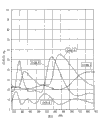
Fig. 5 has drawn the graphic representation according to the total reflectivity of the interference thin flakes of various three layers of gamut of the present invention;
Fig. 6 has drawn the graphic representation according to the total reflectivity of the interference thin flakes of various five layers of gamut of the present invention;
Fig. 7 has drawn the graphic representation according to the total reflectivity of the interference thin flakes of various five layers of gamut of the present invention; With
Fig. 8 has drawn the graphic representation according to the total reflectivity of the interference thin flakes of various three layers of gamut of the present invention;
Detailed description of the present invention
The present invention is absorbed in and can does for the manufacture of the multilayer of the thin slice with gamut performance or paillon foil Relate to film. Described thin slice can be dispersed in various pigment media, such as paint, printing ink or cosmetic In the product preparation, and be then used in object, paper or people, the angle of incident light or observer Realize gamut during visual angle change.
Common method by formation shallow layer structure known in the art is such as physical vapor deposition (PVD) method or chemical vapour deposition (CVD) method forms thin layer described herein. As hereinafter discussing in more detail, coating structure is at a kind of base material, such as a kind of Web materials of softness Upper formation and as film sheet from base material except lower, thin slice is added liquid medium, as various In the pigment carrier, use as the colouring agent with gamut performance. This kind adds in the liquid medium The set of film sheet can produce predetermined to the visible radiation of the dielectric surface that incides curing Photoresponse. Perhaps, can remove coating structure from Web materials with the form of paillon foil.
Because the paillon foil configuration uses as the brand paillon foil usually, the adhesive by thermal activation wherein From the optical laminated base material of removing, paillon foil is normally a kind of inhomogeneous optical laminated. Adhesive Can be coated on optical laminated dorsal part or be coated on light with the form of the adhesive of UV activation On the surface that lamination or paillon foil will be pasted. Can be in U.S. Patent No. 5,648, look in 165 To making and using optical laminated further details as the brand paillon foil, at this by reference The disclosure of incorporating this patent into. Perhaps, can make with optical laminated accompanying ground Use the paillon foil configuration. Submit on July 8th, 1999, name is called " with the gamut background Difraction surface " pending trial U.S. Patent application No.09/351,102 have described and have been attached on the ground An optical laminated useful especially embodiment, incorporate by reference this patent Shen at this Please, wherein form holographic optical elements (HOE) at least one substrate surface.
On the contrary, pigment flakes must have uniform coating structure, no matter so that thin slice with respect to Observer's orientation how, and color is all identical. In this case, coating structure is by uniformly Optical laminated formation so that when optical laminated form with thin plate or thin slice (that is, pigment) from Except lower time, two masks of pigment flakes have identical color on the base material.
Can use various forms of carbon in the present invention, include but not limited to graphite, carbonaceous With unbodied carbon; Vitreous carbon; Diamond-like-carbon; The carbon of amorphous hydrogenated, as do not have and decide The diamond-like-carbon of shape hydrogenation; Carbon compound; The various combinations of above-mentioned carbon etc. Also can utilize By the other forms of carbon with different optical performance that deposition process obtains, for example electric arc steams Send out carbon, the auxiliary carbon I of ion, the auxiliary carbon II of ion etc.
Carbon thin film layer on thin slice of the present invention and the paillon foil has from about 1 to about 2.6 specific refractory power (n).Preferred at least one carbon-coating has and is higher than about 1.5 specific refractory power, more preferably is higher than approximately 1.75, most preferably is higher than about 2.Carbon thin film layer has and is higher than about 0.02 specific absorbance (α), preferably is higher than approximately 0.1, more preferably is higher than approximately 1, most preferably is higher than about 2.Ideally, the value of refractive index and specific absorbance is equal substantially, and making the refractive index and the ratio (n/ α) of specific absorbance approximately is 1.It is about 0.1 to about 10 that the specific absorbance that at least one carbon-coating had in preferred thin slice or the paillon foil makes the ratio of specific refractory power and specific absorbance, more preferably from about 0.5 to about 5, and most preferably from about 0.75 to about 1.25.The optical constant scope of various forms of carbon is summarized among the following table 3-9 and in embodiment 6 and contrasts.
The basis that is found to be that the present invention makes colored interference pigments with the multilayer optical lamination that can use carbon and insulating material, coated interference pigment wherein has tangible gamut or chromatic aberration performance.The difference of membrane structure of the present invention and existing inteferometer coating is to lack the combination of high and low-refraction insulation layer, and metallic reflector and metal absorption layer.Although do not wish to be subjected to the constraint of any theory, but still believe that optical laminated carbon-coating plays a role as high-index material and absorbing material, and produce the gamut effect with the insulation layer co-operation.
With reference to accompanying drawing, wherein refer to similar structure with similar quotation mark, Fig. 1 has described to have the embodiment of three layers of coated designs of interference thin film 10 forms of gamut performance.Film 10 forms on the Web materials 12 of for example a kind of polyester material (for example polyethylene terephthalate or PET) at a kind of flexible materials.Film 10 has 14, one of one first carbon-coatings at first insulation layer 16 on the carbon-coating 14 and second carbon-coating 18 on insulation layer 16.Hereinafter will further go through above-mentioned each layer of film 10.
By the deposition method of routine, for example electron beam evaporation, sputter or on Web materials 12, deposit first carbon-coating 14 of interference thin film 10 by the method that hydrocarbon CVD reaction forms carbon-coating.Formed carbon-coating 14 have from about 25 to about 1000 dusts (
 ) suitable physical thickness, preferably approximately 200-500
, more preferably about 200-300
When using the PVD method, can form carbon-coating 14 as graphite, poco or vitreous carbon by different carbon sources.
) suitable physical thickness, preferably approximately 200-500
, more preferably about 200-300
When using the PVD method, can form carbon-coating 14 as graphite, poco or vitreous carbon by different carbon sources.
Perhaps, can deposit various forms of carbon by various CVD methods, for example those are in U.S. Patent No. 5,190, and method in greater detail in 807 is incorporated the disclosure of this patent into by reference at this.In addition, can use the available form of carbon and carbon compound, as silicon oxide carbide, the SiOx that contains carbon black, its combination etc.Can pass through in U.S. Patent No. 5,356, the method described in 471 deposits these carbon compounds, incorporates the disclosure of this patent by reference at this.
In other selectable methods, can pass through the solid-state polymerization film, form carbon thin film layer as those modifications with solid-state polymerization film that contains polyarylester, polyacrylonitrile, poly-para xylylene etc. of high aromatic content.This kind carbon film is by the solid polymer depositing of thin film, then by the high energy method, changes polymeric film into the carbon film and forms as pyrolysis, ion bombardment etc.
Then by conventional deposition method, as PVD or by U.S. Patent No. 5,858,078 more detailed disclosed SiO
2Sol-gel method forms first insulation layer 16 on carbon-coating 14, incorporate the disclosure of this patent by reference at this.
Formed insulation layer 16 has can give the effective optical thickness of interference thin film 10 with the gamut performance.This optical thickness is by the defined known optical parameter of the nd of product, and wherein n is the specific refractory power of layer, and d is the physical thickness of layer.Usually the optical thickness of layer is with quarter wave optical thickness (QWOT) expression, and QWOT equals 4nd/ λ, the wavelength when λ wherein is definition QWOT condition.Formed insulation layer 16 has and is specifying a plurality of quarter wave optical thicknesses of wavelength.At the specified wavelength of about 400-700nm, this optical thickness scope can be from about 2QWOT to about 9QWOT, and preferably at the specified wavelength of about 400-600nm, this optical thickness is that about 2QWOT is to about 6QWOT.Therefore, the physical thickness of insulation layer 16 is in the scope of the extremely about 1086nm of about 138nm, preferably from the extremely about 725nm of about 140nm.
The insulating material that is used to form insulation layer 16 can have " low " specific refractory power, at this low-refraction is defined as about 1.65 or lower specific refractory power, perhaps can have " height " specific refractory power, at this high refractive index is defined as specific refractory power greater than about 1.65.Preferred employed insulating material has about 1.38 to about 2.3 specific refractory power.Operable different insulating material comprises inorganic materials, as metal oxide, metal fluoride, metallic sulfide, metal nitride, metallic carbide and combination thereof etc., and organic insulation.These materials are easy to obtain and are easy to use by physics or chemical vapor deposition.
The indefiniteness example of the insulating material of operable suitable low-refraction comprises silicon-dioxide (SiO
2), aluminum oxide (Al
2O
3), metal fluoride, for example magnesium fluoride (MgF
2), aluminum fluoride (AlF
3), cerium fluoride (CeF
3), lanthanum fluoride (LaF
3), sodium aluminium fluoride (Na for example
3AlF
6Or Na
5Al
3F
14), neodymium fluoride (NdF
3), samaric fluoride (SmF
3), barium fluoride (BaF
2), Calcium Fluoride (Fluorspan) (CaF
2), lithium fluoride (LiF), and combination or specific refractory power are about 1.65 or the material of lower any other low-refraction.For example, can adopt organic monomer and polymkeric substance as low-index material, comprise diolefine or alkene for example polymkeric substance, tetrafluoroethylene (TEFLON), fluoro second propylene (FEP) polymkeric substance, poly-para xylylene, p-Xylol and the combination thereof etc. of acrylate (for example methacrylic ester), perfluoro alkene.In addition, above-mentioned materials comprises and can incorporate the disclosure of this patent by reference at this by the sedimentary evaporation of method, condensation and the crosslinked transparent acrylate layer of U.S. Patent No. 5,877,895 descriptions.
The high refractive index insulating material that is fit to comprises zinc sulphide (ZnS), zinc oxide (ZnO), zirconium white (ZrO), titanium dioxide (TiO
2), Indium sesquioxide (In
2O
3), tin indium oxide (ITO), tantalum pentoxide (Ta
2O
5), cerium dioxide (CeO
2), yttrium oxide (Y
2O
3), europium sesquioxide (Eu
2O
3), ferric oxide Z 250 (Fe for example
3O
4) and ferric oxide (Fe
2O
3), hafnium nitride (HfN), hafnium carbide (HfC), hafnia (HfO
2), lanthanum trioxide (La
2O
3), magnesium oxide (MgO), Neodymium trioxide (Nd
2O
3), Praseodymium trioxide (Pr
6O
11), Samarium trioxide (Sm
2O
3), weisspiessglanz (Sb
2O
3), silicon carbide (SiC), silicon monoxide (SiO), silicon nitride (Si
3N
4), selenium trioxide (Se
2O
3), stannic oxide (SnO
2), tungstic oxide (WO
3) and combination etc.
Be preferred for insulating material of the present invention and comprise SiO
xMaterial, as silicon-dioxide, silicon monoxide and combination, x wherein is between 1 and 2.Can pass through at O
2The condition deposit SiO that gas exists forms SiO
2Other preferred insulating material comprise MgF
2, Al
2O
3And combination.
On insulation layer 16, form second carbon-coating 18 of interference thin film 10 by conventional deposition method such as PVD, to obtain three layers of interference thin film 10.Can be from forming carbon-coating 18 with the identical source that is used for carbon-coating 16 of above being discussed with identical thickness.With the form of the interference thin flakes of a plurality of gamuts film 10 is removed from Web materials 12 then, can add in the pigment medium and be used as tinting material removing the thin slice that gets off with gamut performance.The pigment medium can comprise various polymeric compositions or organic binder bond, as acrylic melamine, urethane, polyester, Vinylite, acrylate, methyl methacrylate, ABS resin, epoxy resin, vinylbenzene and composition thereof, and other are such as the those of ordinary skill known substances in printing ink and paint formulations field, particularly including the material of those polyester resin-baseds.Perhaps, can from Web materials 12, film 10 be removed with the form of brand paillon foil.As an example, another selection is to make ground and employed optical laminated contact the in antifalsification label.
Fig. 2 has described five layers of coated designs with interference thin film 20 forms of gamut performance according to another embodiment of the invention.Film 20 has three a layer coated inside structure corresponding with film 10, comprises carbon-coating 14, the first insulation layers 16 and another carbon-coatings 18.This coated inside structure is between the two or two insulation layer 22 and the 3rd insulation layer 24.Can use and carbon-coating and the insulation layer that is used for the identical materials of film 10 and forms film 20 with identical thickness range discussed above.
By method with routine, on Web materials 12, form insulation layer 22 as PVD, make film 20 by deposition carbon-coating 14, insulation layer 16 and carbon-coating 18 then.On carbon-coating 18, form insulation layer 24 to finish film 20 by deposition method then.For making a plurality of interference thin flakes or paillon foil, then film 20 is removed from Web materials 12, interference thin flakes or paillon foil can add and be used as the tinting material with gamut performance in the pigment medium.
Fig. 3 has described three layers of coated designs with interference thin film 30 forms of gamut performance according to another embodiment of the invention.Film 30 comprises one first insulation layer 32, the carbon-coating on first insulation layer 34 and second insulation layer 36 on carbon-coating 34.Can use and carbon-coating and the insulation layer that is used for the identical materials of film 10 and forms film 30 with identical thickness range discussed above.
On Web materials 12, form insulation layer 32 by deposition method, deposit carbon-coating 34 and insulation layer 36 manufacturing films 30 then with routine.For making a plurality of interference thin flakes or paillon foil, then film 30 is removed from Web materials 12.
Should be noted in the discussion above that when using SiO
2Or other insulating material with similar specific refractory power are when forming insulation layer on the film 30, and this film can show the function of reduction usually as gamut pigment in paint or printing ink.This is because if film worn into pigment and add in the pigment medium to form paint or printing ink, SiO
2Layer will have and the very proximate specific refractory power much at one of medium, make printing ink or paint have the lead of carbon.But, if the material of selecting high refractive index more is will be because of the specific refractory power of the insulation layer of outside and pigment medium on every side different and produce color as insulation layer.And, if use the higher medium of specific refractory power, so in order to obtain refringence maximum between thin slice skin and the medium, preferred SiO
2Or other specific refractory poweres are lower than the insulating material of medium.
On the contrary, though the refractive index matching way of the embodiment of film shown in Figure 2 20 is identical with film 30, if use SiO
2Insulation layer, the core optics structure C/SiO of film 20
2/ C is still colorific interference functional component.In this case, the SiO of outside
2Layer will play core optics structure C/SiO
2The effect of the protective layer of/C.For in delivery system, being subjected to corrosive paint or ink composite, SiO
2The outer corrosion that will prevent to colorific core optical texture.Therefore, the color of paint or ink composite will be more durable.
Fig. 4 has described five layers of coated designs with interference thin film 40 forms of gamut performance according to another embodiment of the invention.Film 40 has three a layer coated inside structure corresponding with film 30, comprises insulation layer 32, the first carbon-coatings 34 and another insulation layers 36.This coated inside structure is between second carbon-coating 42 and the 3rd carbon-coating 44.Can use and carbon-coating and the insulation layer that is used for the identical materials of film 10 and forms film 40 with identical thickness range discussed above.
Form carbon-coating 42 by the method with routine on Web materials 12, depositing insulating layer 32, carbon-coating 34 and insulation layer 36 are made film 40 then.On insulation layer 36, form carbon-coating 44 to finish film 40 by deposition method then.For making a plurality of interference thin flakes or paillon foil, then film 40 is removed from Web materials 12, interference thin flakes or paillon foil can add in the pigment medium and be used as tinting material.
Behind the multi-coated interference film that forms Fig. 1-4 shown type on the Web materials 12, interference thin film can be removed down from Web materials 12 by using a kind of solvent, form any surface size about 2 to about 200 microns thin slice or platelet.Also can further reduce the size of thin slice as required.For example, can carry out air-flow to thin slice and grind, the size with them under the situation of not damaging their ideal colour characteristics is reduced to about 2-5 micron.Can the gamut thin slice be distributed to as using in the pigment media such as paint, printing ink or cosmetic formulations with the method for routine then.
As selection, can pass through on the upper surface of Web materials, to form at least one first carbon-coating or insulation material layer according to the present invention, and remove following the first layer from Web materials and make the gamut coated interference pigment to obtain a plurality of thin slices.With one or more other the carbon or the insulation material layer coated sheet of basic parcel thin slice, other wherein adjacent layers are formed by the material different with the first layer then.For example, the lamellar structure shown in Figure 1 of Xing Chenging will comprise an insulation layer 16 by this method, form the carbon-coating 14 and 18 of the basic successive carbon coating of wrap insulate layer 16.The lamellar structure shown in Figure 2 of Xing Chenging will comprise the continuous coated substantially insulation layer 22 and 24 that forms the parcel carbon coating by this method.Perhaps, can on Web materials, form film 10 as shown in Figure 1 and remove film, with forming continuous coated substantially insulation layer 22 and 24 parcel thin slices with the form of thin slice.Similarly, formed by this method lamellar structure shown in Figure 3 will comprise a carbon-coating 34, form the insulation layer 32 and 36 of the basic continuous insulation coating of parcel carbon-coating 34.The lamellar structure shown in Figure 4 of Xing Chenging will comprise the continuous coated substantially carbon-coating 42 and 44 that forms the wrap insulate coating by this method.Perhaps, can on Web materials, form film 30 as shown in Figure 3 and remove film, with forming continuous coated substantially carbon-coating 42 and 44 parcel thin slices with the form of thin slice.
In the another kind of selectable embodiment of embodiment shown in Figure 4, can be coated with the film 30 formed interference thin flakes by Fig. 3 with other insulation layers of basic wrap insulate layer 32 and 36, wherein the specific refractory power of other insulation layer is different with the specific refractory power of insulation layer 32 and 32.
The U.S. Patent application No.09/389 of the pending trial that on September 3rd, 1999 submitted to, 962 disclose the appropriate means with one or more layers coated sheet, the name of this patent application is called " method and apparatus for preparing improved coated interference pigment ", incorporates this patent application by reference at this.
Pigment flakes, particulate or the dyestuff that can optionally gamut thin slice and other be had different colors, colourity and brightness mix the color characteristic that needs to obtain.For example, thin slice of the present invention can mix with the conventional pigment of other interfere types or non-interfere type, produces other colors.Can be with thin slice of the present invention with the high chroma or the high reflection platelet of gamut combine to obtain unique color effects, as MgF
2/ Al/MgF
2Platelet or SiO
2/ Al/SiO
2Platelet.Other can comprise lamelliform pigment with the suitable additive of color compositions blended of the present invention, as aluminum slice, graphite flake, glass flake, ferric oxide thin slice, boron nitride thin slice, mica sheet, based on TiO
2The interference mica sheet of coating, based on coated interference pigment of coated interference pigment, metal-insulator material or all insulation material of the silication base material of multilayer chip etc., and non-lamelliform pigment, as aluminium powder, carbon black, ultramarine, cobalt-based pigment, pigment dyestuff or dyestuff, rutile or spinel based mineral dye, natural pigment, mineral dye, as titanium dioxide, talcum powder, china clay etc. and various mixture thereof.For example, can add as aluminium powder or carbon black pigment with control brightness and other colour characteristics.
By using the coated designs of the present invention shown in Fig. 1-4, can make the tinting material of high chroma, wherein Ren Lei eyes can be seen the color effect of variation.Therefore, use the painted article of the paint contain gamut thin slice of the present invention will along with visual angle or object observe relatively eyes angle variation and change color.Change and the performance of gamut though all coated designs of the present invention all have with the visual angle, the design inclination that uses the low-refraction insulating material is in having maximum aberration or colour-change.
By utilizing the color characteristic that obtains tinting material according to the set of high chroma film sheet of the present invention, thin slice wherein produces predetermined optic response to the light that incides slice surfaces.Gamut thin slice of the present invention has the gamut performance of wide region, comprises with the change at the visual angle bigger variation on the bigger variation on the colourity (degree of colour purity) and color and luster (relative color).For example, use the color compositions of interference thin flakes of the present invention can have as gamuts such as magenta-green, gold-green, gold-cyans.
Gamut thin slice of the present invention can be easy to and be used for economically being used for the various uses at object and paper as tinting materials such as paint and printing ink.The example of this type objects and paper comprises motor vehicle, currency and security file, household electrical appliance, building structure, floor, sports goods, electronic package/shell, toy etc.
In addition, it is unstable in environment that carbon back coated interference pigment of the present invention and paillon foil are particularly suitable for metal or metallic compound, perhaps owing to the restriction that is subjected to regulations because of metal or metallic compound inherent toxicity and in response to the character of usefulness metal or metallic compound are not inconsistent and the application that needs in.
The following examples are to provide for the present invention is described, rather than in order to limit the scope of the invention.
Embodiment 1
First insulation layer (at the 4QWOT of 615nm place) that contains SiOx by deposition on the polyester mesh material of 2 Mills is made according to the gamut interference thin film with five layers of design of the present invention, has been coated with organic releasing layer dura mater on the Web materials wherein.Deposit thickness is 25C on first insulation layer
 Carbon-coating, be SiOx second insulation layer (at the 4QWOT of 615nm place) then.After this, deposit thickness is 250 on second insulation layer
 Second carbon-coating, deposit SiOx the 3rd insulation layer (at the 4QWOT of 615nm place) then.Therefore, the coated designs of film is SiOx/C/SiOx/C/SiOx.
2 * 10
-4Under the oxygen atmosphere of torr, form SiOx (SiO by electron beam deposition
2) layer.1 * 10
-5Form carbon-coating by electron beam deposition under torr or the lower pressure, wherein under 7kv voltage, use electron gun current and the copper crucible of 0.3-0.4A.In SiOx and carbon laydown, the distance between material source and the ground is 76cm.
By using acetone spraying dissolving dura mater to discharge thin-film material from the polyester mesh material.Because dura mater dissolves from the polyester mesh material, has so just prepared a plurality of thin slices with above-mentioned coated designs.By the tip of the ultrasonic wave angle of Branston being put into liquid these thin slices that still are in acetone liquid are ground to suitable size.After the several minutes, stop polish process.Filter thin slice from solvent, the concentration with about 25 weight % is dispersed in formation paint in the acrylic melamine tackiness agent once more then.Then paint spraying is used for characterization on metal sheet.
The colored parameter of the metal sheet that the colored survey meter measurement of Zeiss of use outfit multi-angle geometry is sprayed paint, colored parameter is the function of viewing angle that is in the satin angle.Along with the change of angle, colourimetric number is in 36 to 67 scopes.At normal incident visual angle, the painted metals plate is a magenta, and the change along with the visual angle becomes redness, is yellow then, finally is green when very high reflection angle.
Because the interference of carbon back design is transparent a little, found to make that the color performance of the paint sample that added these carbon back pigment is fine because a kind of pigment covers the summation action of another kind of pigment.In other words, the color performance of a kind of color performance of the anchor lacquer that has added this kind pigment single feed thin foil strips of being better than making paints.
Embodiment 2
Make a kind of gamut interference thin film with five layers of design according to the program described in the embodiment 1, difference is in coated designs, whole three SiO
2Layer is to be 4QWOT at the 515nm place.The thickness of carbon-coating is 250
 The thin slice of planting thin film fabrication thus is dispersed in formation paint in the acrylic melamine tackiness agent, this paint spraying is used for color characterizes on metal sheet.Then a kind of transparent spraying external coating (EC) is coated on the part painted metals plate.
At normal incident visual angle, the color of painted metals plate is golden, changes cyan at about 45 degree visual angles.
Colour on the Zeiss instrument shows that the painted metals plate has the colourimetric number of about 50-55, and the part that applies with transparent spraying external coating (EC) has the higher colourity of 55-60.
Embodiment 3
Developed the theoretical gamut thin slice that has according to three layers of coating structure of the present invention, this gamut thin slice has following underlying coating layer design: PET/C/SiO
2/ C/ air, SiO wherein
2Layer has 4QWOT at 550nm, and the thickness of carbon-coating is 25
 To 1,000
Scope.Estimate carbon-coating thickness by the curve of drawing the relative lambda1-wavelength of total reflectivity and be respectively 25
To 1,000
Scope.Estimate carbon-coating thickness by the curve of drawing the relative lambda1-wavelength of total reflectivity and be respectively 25
 , 250
, 250
 , 500
, 500
 With 1,000
 Four kinds of different lamellar structures.Fig. 5 is the reflectivity Characteristics curve that is illustrated in the following four kinds of lamellar structures of different lambda1-wavelengths.Shown in the curve among Fig. 5, though all lamellar structures have to small part gamut characteristic, when using the silicon insulation layer, ideal carbon-coating thickness seemingly 250
 Though this total reflectivity is applicable to the design on the PET ground, if be used for polymerisation medium, when medium places optical laminated two sides, these designs will have similar reflectivity.
Embodiment 4
Developed the theoretical gamut thin slice that has according to five layers of coating structure of the present invention, this gamut thin slice has following underlying coating layer design: PET/SiO
2/ C/SiO
2/ C/SiO
2Air, SiO wherein
2Layer has 4QWOT at 550nm, and the thickness of carbon-coating is 25
To 1,000
 Scope.Estimate carbon-coating thickness by the curve of drawing the relative lambda1-wavelength of total reflectivity and be respectively 25
 , 250
, 250
 , 500
, 500
 With 1,000
 Four kinds of different lamellar structures.Fig. 6 is the curve that is illustrated in the reflectivity Characteristics of the following four kinds of lamellar structures of different lambda1-wavelengths.Shown in the curve among Fig. 6, though all lamellar structures have to small part gamut characteristic, when using the silicon insulation layer, ideal carbon-coating thickness seemingly 250

Embodiment 5
Developed the theoretical gamut thin slice that has according to five layers of coating structure of the present invention, this gamut thin slice has following underlying coating layer design: PET/C/SiO
2/ C/SiO
2/ C/ air, SiO wherein
2Layer has 4QWOT at 550nm, and the thickness of carbon-coating is 25
 To 1,000
 Scope.Estimate carbon-coating thickness by the curve of drawing the relative lambda1-wavelength of total reflectivity and be respectively 25
 , 250
, 250
 , 500
, 500
 With 1,000
 Four kinds of different lamellar structures.Fig. 7 is the curve that is illustrated in the reflectivity Characteristics of the following four kinds of lamellar structures of different lambda1-wavelengths.Shown in the curve among Fig. 7, though all lamellar structures have to small part gamut characteristic, when using the silicon insulation layer, ideal carbon-coating thickness seemingly 250

Following table 1 and 2 has provided the specific refractory power data of the reflectance curve that is used for calculating theoretically above-mentioned Fig. 5, Fig. 6 and Fig. 7, and n wherein is the real part of specific refractory power, and k is optical extinction coefficient (that is the imaginary part of specific refractory power).Optical extinction coefficient is relevant with specific absorbance (α) by following relationship: k=α λ/4 π, wherein λ is a vacuum wavelength.

The SiO that adopts
2Specific refractory power as follows:

Based in this disclosed content, when sedimentary carbon has specific refractory power different with disclosed content among the embodiment 5 and specific absorbance, the thickness that suitably changes carbon-coating in the disclosed mode of embodiment 1-5 will be conspicuous for the those of ordinary skill in optical thin film design and deposition field.
Embodiment 6
By making the simplest coated designs structure, carbon/insulation layer/carbon explanation has the importance of the carbon compound of different specific refractory poweres and dispersion values.Fig. 8 is the curve of this project organization of the multi-form carbon of expression in the reflection characteristic of different lambda1-wavelengths.Following table 3-9 has concluded the optical constant scope of multi-form carbon.Especially, Fig. 8 represents C/SiO
2The theoretical performance of the coated designs of/C type, wherein carbon has the physical thickness of 30nm, SiO
2Physical thickness (that is, wavelength is the quarter wave optical thickness of 508nm) with about 350nm.
Label is the curve of C1 among Fig. 8, and it has maximum total reflection dynamicrange corresponding to having the graphite of listing in optical constant in the table 3, and will show maximum observable reflection gamut.In normal input angle, this specifies the green light of reflection 560nm, and eliminates conversion to shortwave (blue reflected colour) with the increase of incident angle of light.
Curve C 2 and C3 among Fig. 8 show other forms of carbon, has low dynamic color gamut and mild peak slope between near total reflectivity Schwellenwert about 450nm and near the total reflectivity maximum the 508nm as diamond-like carbon, its corresponding optical constant is listed in table 4 and 5, and specific absorbance wherein is lower than about 0.1.This causes showing the conversion of less color and color when input angle increases.
Middle dynamic by the total reflectivity of the represented other forms of carbon of the curve C 4-C7 among Fig. 8 is distributed between curve C 1 and C2, the C3, and its corresponding optical constant is listed in table 6-9.


Suppose in specific refractory power and specific absorbance and do not have chromatic dispersion.


The present invention can comprise other specific forms, and does not depart from its spirit or essential feature.No matter from which point, disclosed embodiment should be regarded as illustrative rather than restrictive.Therefore, defined by the appended claims but not above the description of scope of the present invention.Being in the implication of claim and all modifications in the equivalency range includes in the claim scope.
Claims (90)
1. gamut multi-coated interference film comprises:
First carbon-coating;
Be in first insulation layer on first carbon-coating; With
Be in second carbon-coating on first insulation layer;
Wherein first insulation layer has the optical thickness that produces gamut along with the variation at the angle of incident light or visual angle at specified wavelength place, and wherein the thickness of first carbon-coating is that 20nm is to 100nm.
2. the described interference thin film of claim 1, wherein the physical thickness of first carbon-coating be 25nm to 50nm, and at least one described carbon-coating comprises the material that is selected from graphite, vitreous carbon or its combination.
3. the described interference thin film of claim 1, wherein said carbon has at least 1.0 specific absorbance.
4. the described interference thin film of claim 1, wherein first insulation layer has the optical thickness from 2QWOT to 9QWOT at the specified wavelength from 400nm to 700nm.
5. the described interference thin film of claim 1, wherein first insulation layer has 1.65 or lower specific refractory power.
6. the described interference thin film of claim 5, wherein first insulation layer comprises the material that is selected from the group of being made up of silicon-dioxide, aluminum oxide, magnesium fluoride, aluminum fluoride, cerium fluoride, lanthanum fluoride, sodium aluminium fluoride, neodymium fluoride, samaric fluoride, barium fluoride, Calcium Fluoride (Fluorspan), lithium fluoride and combination thereof.
7. the described interference thin film of claim 5, first insulation layer wherein comprises the material that is selected from the group of being made up of acrylate, perfluoroolefine polymkeric substance, tetrafluoroethylene, poly-para xylylene, polymeric fluorinated ethylene propylene and combination thereof.
8. the described interference thin film of claim 1, first insulation layer wherein have and are higher than 1.65 specific refractory power.
9. the described interference thin film of claim 8, first insulation layer wherein comprises the material that is selected from the group of being made up of zinc sulphide, zinc oxide, zirconium white, titanium dioxide, Indium sesquioxide, tin indium oxide, tantalum pentoxide, cerium dioxide, yttrium oxide, europium sesquioxide, ferric oxide, hafnium nitride, hafnium carbide, hafnia, lanthanum trioxide, magnesium oxide, Neodymium trioxide, Praseodymium trioxide, Samarium trioxide, ANTIMONY TRIOXIDE SB 203 99.8 PCT, silicon carbide, silicon nitride, silicon monoxide, selenium trioxide, stannic oxide, tungstic oxide and combination thereof.
10. the described interference thin film of claim 1, first insulation layer wherein has from 1.38 to 2.3 specific refractory power.
11. the described interference thin film of claim 1, film wherein forms a plurality of multilayer interference thin flakes.
12. the described interference thin film of claim 1, film wherein forms the brand paillon foil.
13. the described interference thin film of claim 2 also comprises being in second insulation layer on first carbon-coating and being in the 3rd insulation layer on second carbon-coating.
14. the described interference thin film of claim 13, the second and the 3rd insulation layer wherein all has the optical thickness from 2QWOT to 9QWOT at the specified wavelength from 400nm to 700nm.
15. the described interference thin film of claim 13, wherein first, second has identical optical thickness with the 3rd insulation layer.
16. the described interference thin film of claim 13, wherein first, second and the 3rd insulation layer all have from 1.38 to 2.3 specific refractory power.
17. the described interference thin film of claim 16, wherein first, second and the 3rd insulation layer are made up of the material that is selected from the group of being made up of silicon monoxide, silicon-dioxide and combination thereof.
18. the described interference thin film of claim 13, wherein first, second and the 3rd insulation layer are made up of identical materials.
19. the described interference thin film of claim 13, film wherein form a plurality of multilayer interference thin flakes or brand paillon foil.
20. the described interference thin film of claim 1, wherein at least one carbon-coating has and is higher than 1.5 specific refractory power.
21. the described interference thin film of claim 1, wherein at least one carbon-coating has the ratio of from 0.1 to 10 specific refractory power and specific absorbance.
22. the described interference thin film of claim 1, wherein first and second carbon-coatings form the basic continuous coating of parcel first insulation layer.
23. the described interference thin film of claim 13, the second and the 3rd insulation layer wherein forms the basic continuous coating of parcel first and second carbon-coatings.
24. the described interference thin film of claim 1, wherein said carbon deposits by electron beam evaporation.
25. a gamut multi-coated interference film comprises
First insulation layer;
The thickness that is on first insulation layer is first carbon-coating of 25-100nm; With
Be in second insulation layer on first carbon-coating;
Wherein first and second insulation layers all have the optical thickness that produces gamut along with the variation at the angle of incident light or visual angle at specified wavelength place.
26. claim 25 is described in relating to film, wherein the physical thickness of first carbon-coating be 25nm to 50nm, and at least one described carbon-coating comprises the material that is selected from graphite, vitreous carbon or its combination.
27. the described interference thin film of claim 25, first and second insulation layers wherein all have the optical thickness from 2QWOT to 9QWOT at the specified wavelength from 400nm to 700nm.
28. the described interference thin film of claim 25, wherein first and second insulation layers all have 1.65 or lower specific refractory power.
29. the described interference thin film of claim 28, first and second insulation layers wherein comprise the material that is selected from the group of being made up of silicon-dioxide, aluminum oxide, magnesium fluoride, aluminum fluoride, cerium fluoride, lanthanum fluoride, sodium aluminium fluoride, neodymium fluoride, samaric fluoride, barium fluoride, Calcium Fluoride (Fluorspan), lithium fluoride and combination thereof.
30. the described interference thin film of claim 28, first and second insulation layers wherein comprise the material that is selected from the group of being made up of acrylate, perfluoroolefine, tetrafluoroethylene, fluorinated ethylene propylene and combination thereof.
31. having, the described interference thin film of claim 25, first and second insulation layers wherein be higher than 1.65 specific refractory power.
32. the described interference thin film of claim 31, first and second insulation layers wherein comprise the material that is selected from the group of being made up of zinc sulphide, zinc oxide, zirconium white, titanium dioxide, Indium sesquioxide, tin indium oxide, tantalum pentoxide, cerium dioxide, yttrium oxide, europium sesquioxide, ferric oxide, hafnium nitride, hafnium carbide, hafnia, lanthanum trioxide, magnesium oxide, Neodymium trioxide, Praseodymium trioxide, Samarium trioxide, ANTIMONY TRIOXIDE SB 203 99.8 PCT, silicon carbide, silicon nitride, silicon monoxide, selenium trioxide, stannic oxide, tungstic oxide and combination thereof.
33. the described interference thin film of claim 25, first and second insulation layers wherein all have from 1.38 to 2.3 specific refractory power.
34. the described interference thin film of claim 33, first and second insulation layers wherein are made up of the material that is selected from the group of being made up of silicon monoxide, silicon-dioxide and combination thereof.
35. the described interference thin film of claim 25, film wherein form a plurality of multilayer interference thin flakes or brand paillon foil.
36. the described interference thin film of claim 25 also comprises being in second carbon-coating on first insulation layer and being in the 3rd carbon-coating on second insulation layer.
37. the described interference thin film of claim 36, the second and the 3rd carbon-coating wherein has from the physical thickness of 25 dust to 1000 dusts.
38. the described interference thin film of claim 36, wherein first, second has identical physical thickness with the 3rd carbon-coating.
39. the described interference thin film of claim 36, film wherein form a plurality of multilayer interference thin flakes or brand paillon foil.
40. having, the described interference thin film of claim 36, at least one carbon-coating wherein be higher than 1.5 specific refractory power.
41. the described interference thin film of claim 36, wherein at least one carbon-coating has the ratio of from 0.1 to 10 specific refractory power and specific absorbance.
42. the described interference thin film of claim 25, first and second insulation layers wherein form the basic continuous coating of parcel first carbon-coating.
43. the described interference thin film of claim 36, the second and the 3rd carbon-coating wherein forms the basic continuous coating of parcel first and second insulation layers.
44. the described interference thin film of claim 25 also comprises the 3rd insulation layer that wraps up first and second insulation layers basically, wherein the specific refractory power of the 3rd insulation layer is different from the specific refractory power of first and second insulation layers.
45. a gamut color compositions comprises:
A kind of pigment medium; With
Be dispersed in a plurality of gamut multilayer interference thin flakes in the pigment medium, each interference thin flakes comprises:
First carbon-coating;
Be in first insulation layer on first carbon-coating; With
Be in second carbon-coating on first insulation layer;
Wherein first insulation layer has the optical thickness that can produce gamut along with the variation at the angle of incident light or visual angle at specified wavelength place, and wherein the thickness of first carbon-coating is that 20nm is to 100nm.
46. the described color compositions of claim 45, pigment medium wherein comprise the material that is selected from the group of being made up of the ink of acrylic melamine, urethane, polyester, Vinylite, acrylate, methyl methacrylate, ABS resin, epoxy resin, vinylbenzene, polyester resin-based and ink formulations and composition thereof.
47. the described color compositions of claim 45, first and second carbon-coatings wherein all have from the physical thickness of 200 dust to 500 dusts, and at least one described carbon-coating comprises the material that is selected from graphite, vitreous carbon or its combination.
48. the described color compositions of claim 45, wherein first insulation layer has the optical thickness from 2QWOT to 6QWOT at the specified wavelength from 400nm to 600nm.
49. the described color compositions of claim 45, first insulation layer wherein comprises the material that is selected from the group of being made up of silicon-dioxide, aluminum oxide, magnesium fluoride, aluminum fluoride, cerium fluoride, lanthanum fluoride, sodium aluminium fluoride, neodymium fluoride, samaric fluoride, barium fluoride, Calcium Fluoride (Fluorspan), lithium fluoride and combination thereof.
50. the described color compositions of claim 45, first insulation layer wherein comprise the material that is selected from the group of being made up of acrylate, perfluoroolefine polymkeric substance, tetrafluoroethylene, fluorizated ethylene propylene polymerization thing, poly-para xylylene and combination thereof.
51. the described color compositions of claim 45, first insulation layer wherein comprises the material that is selected from the group of being made up of zinc sulphide, zinc oxide, zirconium white, titanium dioxide, Indium sesquioxide, tin indium oxide, tantalum pentoxide, cerium dioxide, yttrium oxide, europium sesquioxide, ferric oxide, hafnium nitride, hafnium carbide, hafnia, lanthanum trioxide, magnesium oxide, Neodymium trioxide, Praseodymium trioxide, Samarium trioxide, ANTIMONY TRIOXIDE SB 203 99.8 PCT, silicon carbide, silicon nitride, silicon monoxide, selenium trioxide, stannic oxide, tungstic oxide and combination thereof.
52. the described color compositions of claim 45, first insulation layer wherein has from 1.38 to 2.3 specific refractory power.
Be in second insulation layer on first carbon-coating and be in the 3rd insulation layer on second carbon-coating 53. the described color compositions of claim 45, interference thin flakes wherein also comprise.
54. the described color compositions of claim 53, wherein first, second has identical optical thickness with the 3rd insulation layer.
55. the described color compositions of claim 53, wherein first, second and the 3rd insulation layer are made up of identical materials.
56. the described color compositions of claim 45 also comprises the interpolation material that is selected from the group of being made up of lamelliform pigment, non-lamelliform pigment, high chroma platelet, high reflection platelet and composition thereof.
57. the described color compositions of claim 56, lamelliform pigment wherein are selected from by aluminum slice, graphite flake, mica sheet, glass flake, ferric oxide thin slice, boron nitride thin slice, based on TiO
2The interference mica sheet of coating, the group of being formed based on coated interference pigment of coated interference pigment, metal-insulator material or all insulation material of the silication base material of multilayer chip and composition thereof.
58. the described color compositions of claim 56, non-lamelliform pigment wherein is selected from the group of being made up of mineral dye, aluminium powder, carbon black, ultramarine, cobalt-based pigment, rutile or spinel based mineral dye, natural pigment, pigment dyestuff or dyestuff and composition thereof.
59. the described color compositions of claim 56, height reflection platelet wherein is MgF
2/ Al/MgF
2Platelet or SiO
2/ Al/SiO
2Platelet.
60. the described color compositions of claim 45, wherein at least one carbon-coating has and is higher than 1.5 specific refractory power.
61. the described color compositions of claim 45, wherein at least one carbon-coating has the ratio of from 0.1 to 1.0 specific refractory power and specific absorbance.
62. the described color compositions of claim 45, first and second carbon-coatings wherein form the basic continuous coating of parcel first insulation layer.
63. the described color compositions of claim 53, the second and the 3rd insulation layer wherein forms the basic continuous coating of parcel first and second carbon-coatings.
64. a gamut color compositions comprises:
A kind of pigment medium; With
Be dispersed in a plurality of gamut multilayer interference thin flakes in the pigment medium, each interference thin flakes comprises:
First insulation layer;
The thickness that is on first insulation layer is first carbon-coating of 20-100nm; With
Be in second insulation layer on first carbon-coating;
Wherein first and second insulation layers have the optical thickness that can produce gamut along with the variation at the angle of incident light or visual angle at specified wavelength place.
65. the described color compositions of claim 64, pigment medium wherein comprise the material that is selected from the group of being made up of the ink of acrylic melamine, urethane, polyester, Vinylite, acrylate, methyl methacrylate, ABS resin, epoxy resin, vinylbenzene, polyester resin-based and ink formulations and composition thereof.
66. the described color compositions of claim 64, wherein the physical thickness of first carbon-coating for about 20nm to 50nm, and at least one described carbon-coating comprises the material that is selected from graphite, vitreous carbon or its combination.
67. the described color compositions of claim 64, first and second insulation layers wherein all have the optical thickness from 2QWOT to 6QWOT at the specified wavelength from 400nm to 600nm.
68. the described color compositions of claim 64, first and second insulation layers wherein comprise the material that is selected from the group of being made up of silicon-dioxide, aluminum oxide, magnesium fluoride, aluminum fluoride, cerium fluoride, lanthanum fluoride, sodium aluminium fluoride, neodymium fluoride, samaric fluoride, barium fluoride, Calcium Fluoride (Fluorspan), lithium fluoride and combination thereof.
69. the described color compositions of claim 64, first and second insulation layers wherein comprise the material that is selected from the group of being made up of acrylate, perfluoroolefine polymkeric substance, tetrafluoroethylene, fluorizated ethylene propylene polymerization thing, poly-para xylylene and combination thereof.
70. the described color compositions of claim 64, first and second insulation layers wherein comprise the material that is selected from the group of being made up of zinc sulphide, zinc oxide, zirconium white, titanium dioxide, Indium sesquioxide, tin indium oxide, tantalum pentoxide, cerium dioxide, yttrium oxide, europium sesquioxide, ferric oxide, hafnium nitride, hafnium carbide, hafnia, lanthanum trioxide, magnesium oxide, Neodymium trioxide, Praseodymium trioxide, Samarium trioxide, ANTIMONY TRIOXIDE SB 203 99.8 PCT, silicon carbide, silicon nitride, silicon monoxide, selenium trioxide, stannic oxide, tungstic oxide and combination thereof.
71. the described color compositions of claim 64, first and second insulation layers wherein all have from 1.38 to 2.3 specific refractory power.
Be in second carbon-coating on first insulation layer and be in the 3rd carbon-coating on second insulation layer 72. the described color compositions of claim 64, interference thin flakes wherein also comprise.
73. the described interference thin film of claim 72, wherein first, second has identical physical thickness with the 3rd carbon-coating.
74. the described color compositions of claim 64 also comprises the interpolation material that is selected from the group of being made up of lamelliform pigment, non-lamelliform pigment, high chroma platelet, high reflection platelet and composition thereof.
75. the described color compositions of claim 74, lamelliform pigment wherein are selected from by aluminum slice, graphite flake, mica sheet, glass flake, ferric oxide thin slice, boron nitride thin slice, based on TiO
2The group that coated interference pigment of the interference mica sheet of coating, the coated interference pigment based on multilayer chip silication base material, metal-insulator material or all insulation material and composition thereof is formed.
76. the described color compositions of claim 74, non-lamelliform pigment wherein is selected from the group of being made up of mineral dye, aluminium powder, carbon black, ultramarine, cobalt-based pigment, rutile or spinel based mineral dye, natural pigment, pigment dyestuff or dyestuff and composition thereof.
77. the described color compositions of claim 74, height reflection platelet wherein is MgF
2/ Al/MgF
2Platelet or SiO
2/ Al/SiO
2Platelet.
78. the described color compositions of claim 72, wherein at least one carbon-coating has and is higher than 1.5 specific refractory power.
79. the described color compositions of claim 72, wherein at least one carbon-coating has the ratio of from 0.1 to 1.0 specific refractory power and specific absorbance.
60. the described color compositions of claim 64, first and second insulation layers wherein form the basic continuous coating of parcel first insulation layer.
81. the described color compositions of claim 72, the second and the 3rd carbon-coating wherein forms the basic continuous coating of parcel first and second insulation layers.
82. a method of making the gamut coated interference pigment comprises the following steps:
Forming thickness on the upper surface of Web materials is first carbon-coating of 20-100nm;
On first carbon-coating, form first insulation layer;
On first insulation layer, form second carbon-coating to form interference thin film; With
Interference thin film is removed down making a plurality of multilayer interference thin flakes or paillon foil from Web materials, and at least one described carbon-coating comprises the material that is selected from graphite, vitreous carbon or its combination.
83. the described method of claim 82, also be included in remove interference thin film from Web materials before, in the step that forms second insulation layer and on second insulation layer, form the 3rd carbon-coating on second carbon-coating.
84. the described method of claim 82 also comprises interference thin flakes and pigment medium blended step.
85. the described method of claim 82 also comprises the step with second insulation layer coating interference thin flakes of basic parcel first and second carbon-coatings.
86. a method of making the gamut coated interference pigment comprises the following steps:
On the upper surface of Web materials, form first insulation layer;
On first insulation layer, form first carbon-coating, wherein the physical thickness of first carbon-coating for about 20nm to 50nm, and wherein first carbon-coating is graphite or vitreous carbon;
On first carbon-coating, form second insulation layer to form interference thin film; With
Interference thin film is removed down to make a plurality of multilayer interference thin flakes or paillon foil from Web materials.
87. the described method of claim 86, also be included in remove interference thin film from Web materials before, in the step that forms second carbon-coating and on second carbon-coating, form the 3rd insulation layer on second insulation layer.
88. the described method of claim 86 also comprises interference thin flakes and pigment medium blended step.
89. the described method of claim 86 also comprises the step with second carbon-coating coating interference thin flakes of basic parcel first and second insulation layers.
90. the described method of claim 86 comprises that also wherein the specific refractory power of the 3rd insulation layer is different with the specific refractory power of first and second insulation layers with the step of the 3rd insulation layer coating interference thin flakes of basic parcel first and second insulation layers.
Applications Claiming Priority (2)
| Application Number | Priority Date | Filing Date | Title |
|---|---|---|---|
| US09/420,717 US6545809B1 (en) | 1999-10-20 | 1999-10-20 | Color shifting carbon-containing interference pigments |
| US09/420,717 | 1999-10-20 |
Publications (2)
| Publication Number | Publication Date |
|---|---|
| CN1451029A CN1451029A (en) | 2003-10-22 |
| CN100441639C true CN100441639C (en) | 2008-12-10 |
Family
ID=23667573
Family Applications (1)
| Application Number | Title | Priority Date | Filing Date |
|---|---|---|---|
| CNB008145849A Expired - Lifetime CN100441639C (en) | 1999-10-20 | 2000-07-10 | Color shifting carbon-containing interference pigments |
Country Status (8)
| Country | Link |
|---|---|
| US (5) | US6545809B1 (en) |
| EP (2) | EP1230307B1 (en) |
| JP (1) | JP4925154B2 (en) |
| CN (1) | CN100441639C (en) |
| AU (1) | AU6083500A (en) |
| CA (1) | CA2388375C (en) |
| TW (1) | TWI276670B (en) |
| WO (1) | WO2001029137A1 (en) |
Cited By (1)
| Publication number | Priority date | Publication date | Assignee | Title |
|---|---|---|---|---|
| CN107124885A (en) * | 2014-12-12 | 2017-09-01 | 默克专利股份有限公司 | Conductive colored interference pigments |
Families Citing this family (101)
| Publication number | Priority date | Publication date | Assignee | Title |
|---|---|---|---|---|
| US20070195392A1 (en) * | 1999-07-08 | 2007-08-23 | Jds Uniphase Corporation | Adhesive Chromagram And Method Of Forming Thereof |
| US7517578B2 (en) * | 2002-07-15 | 2009-04-14 | Jds Uniphase Corporation | Method and apparatus for orienting magnetic flakes |
| US7604855B2 (en) * | 2002-07-15 | 2009-10-20 | Jds Uniphase Corporation | Kinematic images formed by orienting alignable flakes |
| US6761959B1 (en) * | 1999-07-08 | 2004-07-13 | Flex Products, Inc. | Diffractive surfaces with color shifting backgrounds |
| US7047883B2 (en) | 2002-07-15 | 2006-05-23 | Jds Uniphase Corporation | Method and apparatus for orienting magnetic flakes |
| US7667895B2 (en) * | 1999-07-08 | 2010-02-23 | Jds Uniphase Corporation | Patterned structures with optically variable effects |
| US11768321B2 (en) | 2000-01-21 | 2023-09-26 | Viavi Solutions Inc. | Optically variable security devices |
| CN1666888B (en) * | 2000-01-21 | 2011-12-14 | 光学涂层实验公司 | Optically variable security devices |
| US20060012881A1 (en) * | 2000-05-25 | 2006-01-19 | Atomic Telecom | Atomic layer controlled optical filter design for next generation dense wavelength division multiplexer |
| US6930835B2 (en) * | 2000-05-25 | 2005-08-16 | Atomic Telecom | Atomic layer controlled optical filter design for next generation dense wavelength division multiplexer |
| GB0015873D0 (en) * | 2000-06-28 | 2000-08-23 | Rue De Int Ltd | Optically variable security device |
| US7625632B2 (en) * | 2002-07-15 | 2009-12-01 | Jds Uniphase Corporation | Alignable diffractive pigment flakes and method and apparatus for alignment and images formed therefrom |
| JP2003057567A (en) * | 2001-08-16 | 2003-02-26 | Sony Corp | Optical multi-layered structure, optical switching element and its manufacturing method, and image display device |
| MXPA04002266A (en) * | 2001-09-14 | 2004-06-29 | Merck Patent Gmbh | Moulded bodies consisting of core-shell particles. |
| US6888305B2 (en) * | 2001-11-06 | 2005-05-03 | Universal Display Corporation | Encapsulation structure that acts as a multilayer mirror |
| JP3979138B2 (en) * | 2001-12-20 | 2007-09-19 | 住友電気工業株式会社 | Optical isolator and polarizer |
| DE10204339A1 (en) * | 2002-02-01 | 2003-08-07 | Merck Patent Gmbh | Strain and compression sensor |
| DE10204338A1 (en) * | 2002-02-01 | 2003-08-14 | Merck Patent Gmbh | Shaped body made of core-shell particles |
| DE10207622A1 (en) * | 2002-02-22 | 2003-09-04 | Giesecke & Devrient Gmbh | Security document and security element for a security document |
| US6777085B1 (en) * | 2002-04-19 | 2004-08-17 | Optical Coating Laboratory, Inc. | Article and method of preparing pigments using multiple deposition sources |
| US7097923B2 (en) * | 2002-04-30 | 2006-08-29 | Hitachi Global Storage Technologies | Method for forming thin film heads using a tri-layer anti-reflection coating for photolithographic applications and a structure thereof |
| DE10227071A1 (en) * | 2002-06-17 | 2003-12-24 | Merck Patent Gmbh | Composite material containing core-shell particles |
| US7934451B2 (en) | 2002-07-15 | 2011-05-03 | Jds Uniphase Corporation | Apparatus for orienting magnetic flakes |
| US11230127B2 (en) | 2002-07-15 | 2022-01-25 | Viavi Solutions Inc. | Method and apparatus for orienting magnetic flakes |
| US20100208351A1 (en) * | 2002-07-15 | 2010-08-19 | Nofi Michael R | Selective and oriented assembly of platelet materials and functional additives |
| US8025952B2 (en) | 2002-09-13 | 2011-09-27 | Jds Uniphase Corporation | Printed magnetic ink overt security image |
| US9164575B2 (en) * | 2002-09-13 | 2015-10-20 | Jds Uniphase Corporation | Provision of frames or borders around pigment flakes for covert security applications |
| US7674501B2 (en) * | 2002-09-13 | 2010-03-09 | Jds Uniphase Corporation | Two-step method of coating an article for security printing by application of electric or magnetic field |
| US7645510B2 (en) * | 2002-09-13 | 2010-01-12 | Jds Uniphase Corporation | Provision of frames or borders around opaque flakes for covert security applications |
| US9458324B2 (en) | 2002-09-13 | 2016-10-04 | Viava Solutions Inc. | Flakes with undulate borders and method of forming thereof |
| US20080236447A1 (en) * | 2002-09-13 | 2008-10-02 | Jds Uniphase Corporation | Flake For Covert Security Applications |
| DE10245848A1 (en) * | 2002-09-30 | 2004-04-01 | Merck Patent Gmbh | Process for the production of inverse opal structures |
| US8007772B2 (en) * | 2002-10-02 | 2011-08-30 | L'oreal S.A. | Compositions to be applied to the skin and the integuments |
| US20060018854A1 (en) * | 2002-10-02 | 2006-01-26 | Christophe Dumousseaux | Cosmetic compositions |
| AU2003301972A1 (en) * | 2002-11-13 | 2004-06-03 | Ciba Specialty Chemicals Holding Inc. | Novel interference pigments |
| US6811274B2 (en) | 2002-12-04 | 2004-11-02 | General Electric Company | Polarization sensitive optical substrate |
| AU2003294393A1 (en) * | 2002-12-04 | 2004-06-23 | Sabic Innovative Plastics Ip B.V. | High index of refraction coated light management films |
| US20050008595A1 (en) * | 2003-05-16 | 2005-01-13 | Duffournier Franck Girier | Cosmetic compositions with optical variability |
| FR2856078B1 (en) * | 2003-06-16 | 2006-11-17 | Commissariat Energie Atomique | COATING FOR A MECHANICAL PART COMPRISING AT LEAST HYDROGENATED AMORPHOUS CARBON AND METHOD OF DEPOSITING SUCH COATING. |
| US7550197B2 (en) * | 2003-08-14 | 2009-06-23 | Jds Uniphase Corporation | Non-toxic flakes for authentication of pharmaceutical articles |
| FR2859487B1 (en) * | 2003-09-04 | 2006-12-15 | Essilor Int | METHOD FOR DEPOSITING AN AMORPHOUS LAYER CONTAINING MAJORITARILY FLUORINE AND CARBON AND DEVICE SUITABLE FOR ITS IMPLEMENTATION |
| WO2005064035A1 (en) * | 2003-12-23 | 2005-07-14 | Dipl.-Ing. Hilmar Weinert Vakuum-Verfahrenstechnik Gmbh | Production of small thin plates made of at least one dielectric material |
| US20050238979A1 (en) * | 2004-04-08 | 2005-10-27 | Christophe Dumousseaux | Compositions for application to the skin, to the lips, to the nails, and/or to hair |
| US7981404B2 (en) * | 2004-04-08 | 2011-07-19 | L'oreal S.A. | Composition for application to the skin, to the lips, to the nails, and/or to hair |
| US20050257715A1 (en) * | 2004-04-08 | 2005-11-24 | Christophe Dumousseaux | Compositions for application to the skin, to the lips, to the nails, and/or to hair |
| DE102004018723A1 (en) * | 2004-04-17 | 2005-11-03 | Wella Ag | Itaconic acid monoester / acrylate copolymer and polystyrenesulfonate containing hair treatment agent |
| DE102004032120A1 (en) * | 2004-07-01 | 2006-02-09 | Merck Patent Gmbh | Diffractive colorants for cosmetics |
| FR2876011B1 (en) * | 2004-10-05 | 2006-12-29 | Oreal | METHOD FOR MAKE-UP A SUPPORT AND KIT FOR IMPLEMENTING SAID METHOD |
| WO2006037901A1 (en) * | 2004-10-05 | 2006-04-13 | L'oreal | Make-up kit and method |
| US9649261B2 (en) | 2004-10-05 | 2017-05-16 | L'oreal | Method of applying makeup to a surface and a kit for implementing such a method |
| US20060202469A1 (en) * | 2005-03-10 | 2006-09-14 | Neil Teitelbaum | Financial instrument having indicia related to a security feature thereon |
| TWI402106B (en) | 2005-04-06 | 2013-07-21 | Jds Uniphase Corp | Dynamic appearance-changing optical devices (dacod) printed in a shaped magnetic field including printable fresnel structures |
| CA2537732A1 (en) * | 2005-04-06 | 2006-10-06 | Jds Uniphase Corporation | High chroma optically variable colour-shifting glitter |
| FR2888115B1 (en) * | 2005-07-08 | 2013-02-15 | Oreal | LIQUID FOUNDATION, MAKE - UP PROCESS AND KIT FOR IMPLEMENTING SUCH A METHOD. |
| FR2889921B1 (en) | 2005-08-30 | 2007-12-28 | Oreal | CONDITIONING AND APPLICATION ASSEMBLY COMPRISING A MAGNETIC DEVICE. |
| CA2564764C (en) * | 2005-10-25 | 2014-05-13 | Jds Uniphase Corporation | Patterned optical structures with enhanced security feature |
| JP2007134464A (en) * | 2005-11-09 | 2007-05-31 | Canon Inc | Optical element including multilayer film and exposing apparatus comprising the same |
| CA2570965A1 (en) * | 2005-12-15 | 2007-06-15 | Jds Uniphase Corporation | Security device with metameric features using diffractive pigment flakes |
| US8518445B2 (en) * | 2006-01-20 | 2013-08-27 | Research Foundation Of The City University Of New York | Changing skin-color perception using quantum and optical principles in cosmetic preparations |
| CA2592667C (en) * | 2006-07-12 | 2014-05-13 | Jds Uniphase Corporation | Stamping a coating of cured field aligned special effect flakes and image formed thereby |
| JP2009193069A (en) | 2008-02-13 | 2009-08-27 | Jds Uniphase Corp | Medium for laser printing including optical special effect flake |
| CA2719793C (en) | 2008-04-02 | 2014-10-07 | Sicpa Holding Sa | Identification and authentication using liquid crystal material markings |
| US20090311496A1 (en) * | 2008-06-17 | 2009-12-17 | Ford Global Technologies, Llc | Intermediate Coating Compositions and Methods of Using the Same |
| US8498033B2 (en) * | 2008-09-05 | 2013-07-30 | Jds Uniphase Corporation | Optical device exhibiting color shift upon rotation |
| EP2361187B1 (en) * | 2008-10-03 | 2018-08-08 | Sicpa Holding Sa | Paired optically variable security element having specific reflection wavelengths |
| KR101563156B1 (en) * | 2009-01-13 | 2015-10-27 | 삼성전자주식회사 | Reflective structure display apparatus comprising reflective structure and methods of manufacturing reflective structure and display apparatus |
| CN102369081B (en) * | 2009-03-30 | 2015-09-02 | 伯格利-格拉维瑞斯股份有限公司 | For using the second laser of pulse within the scope of the first laser instrument of pulse in nano-seconds and psec or femtosecond there is the method and apparatus of the surface of solids of hard-coating |
| UY32530A (en) | 2009-04-02 | 2010-10-29 | Sicpa Holding Sa | IDENTIFICATION AND AUTHENTICATION USING POLYMER LIQUID CRYSTAL MATERIAL MARKS |
| GB2477930A (en) * | 2010-02-17 | 2011-08-24 | Tioxide Europe Ltd | Solar reflective system |
| GB2477932A (en) * | 2010-02-17 | 2011-08-24 | Tioxide Europe Ltd | Layered coloured reflector containing particles with rutile crystal habit and specified size |
| JP5781880B2 (en) * | 2010-09-29 | 2015-09-24 | トヨタ モーター エンジニアリング アンド マニュファクチャリング ノース アメリカ,インコーポレイティド | Structural color with UV reflectivity via layer-by-layer spray method |
| KR20120108565A (en) * | 2011-03-24 | 2012-10-05 | 엘지디스플레이 주식회사 | Reflector and display device having the same |
| JP5708504B2 (en) * | 2012-01-06 | 2015-04-30 | コニカミノルタ株式会社 | Pigment having dielectric multilayer structure and paint containing the same |
| IN2014MN01816A (en) | 2012-01-12 | 2015-06-12 | Jds Uniphase Corp | |
| US9796856B2 (en) | 2012-10-01 | 2017-10-24 | Viavi Solutions Inc. | Colorant including a mixture of pigments |
| US20140255608A1 (en) * | 2013-03-11 | 2014-09-11 | Ppg Industries Ohio, Inc. | Coatings that exhibit a tri-coat appearance, related coating methods and substrates |
| US9168209B2 (en) | 2013-03-13 | 2015-10-27 | Johnson & Johnson Consumer Inc. | Pigmented skin-care compositions |
| US9168394B2 (en) | 2013-03-13 | 2015-10-27 | Johnson & Johnson Consumer Inc. | Pigmented skin-care compositions |
| US9320687B2 (en) | 2013-03-13 | 2016-04-26 | Johnson & Johnson Consumer Inc. | Pigmented skin-care compositions |
| US9168393B2 (en) | 2013-03-13 | 2015-10-27 | Johnson & Johnson Consumer Inc. | Pigmented skin-care compositions |
| US10738206B2 (en) | 2013-05-02 | 2020-08-11 | Melior Innovations, Inc. | Black ceramic additives, pigments, and formulations |
| US9481781B2 (en) | 2013-05-02 | 2016-11-01 | Melior Innovations, Inc. | Black ceramic additives, pigments, and formulations |
| US11351652B2 (en) | 2013-05-02 | 2022-06-07 | Melior Innovations, Inc. | Polysilocarb binders and coatings |
| US10787574B2 (en) * | 2014-02-28 | 2020-09-29 | Melior Innovations, Inc. | Polymer derived ceramic effects particles, uses and methods of making |
| US9205304B1 (en) | 2014-10-17 | 2015-12-08 | Acushnet Company | Multi-coating layer color golf ball |
| US11034841B2 (en) * | 2014-11-24 | 2021-06-15 | Basf Corporation | Carbon black in effect pigments |
| DE102014018275A1 (en) * | 2014-12-12 | 2016-06-16 | Merck Patent Gmbh | Non-metallic pigments with metallic properties |
| JP7195739B2 (en) * | 2015-06-30 | 2022-12-26 | ジャイスワル、スプリヤ | Coatings for deep UV and soft X-ray optics |
| WO2017091675A1 (en) * | 2015-11-23 | 2017-06-01 | Basf Corporation | Carbon black in effect pigments |
| US10928579B2 (en) | 2016-06-27 | 2021-02-23 | Viavi Solutions Inc. | Optical devices |
| US10207479B2 (en) | 2016-06-27 | 2019-02-19 | Viavi Solutions Inc. | Magnetic articles |
| EP3269780A1 (en) | 2016-06-27 | 2018-01-17 | Viavi Solutions Inc. | High chroma flakes |
| EP3589709A4 (en) * | 2016-09-09 | 2021-08-18 | Melior Innovations Inc. | Surface effect polymer derived ceramics, methods, materials and uses |
| GB201700711D0 (en) * | 2017-01-16 | 2017-03-01 | Parker Andrew Richard | Application of an optical effect |
| CN111093967A (en) | 2017-10-05 | 2020-05-01 | 伟福夫特科技公司 | Optical structure providing a bicolor effect |
| WO2019084329A2 (en) | 2017-10-25 | 2019-05-02 | Melior Innovations, Inc. | SiOC CERAMIC AND PLASTIC ADDITIVES FOR CEMENTS, CONCRETES AND STRUCTURAL DECORATIVE MATERIALS |
| DE102018104932A1 (en) * | 2018-03-05 | 2019-09-05 | Osram Opto Semiconductors Gmbh | Method for producing a multilayer optical element |
| MX2019002665A (en) * | 2018-03-14 | 2019-09-16 | Viavi Solutions Inc | Solvent-less method to manufacture thin film devices. |
| EP3938218A4 (en) | 2019-04-04 | 2022-11-30 | Wavefront Technology, Inc. | Optical structures providing dichroic effects |
| TW202124596A (en) * | 2019-09-20 | 2021-07-01 | 德商麥克專利有限公司 | Pigments |
| CN112526645B (en) * | 2020-12-03 | 2023-07-25 | 艾普偏光科技(厦门)有限公司 | F-P Fabry-Perot technology visible light color-changing lens and spectacle lens |
Citations (4)
| Publication number | Priority date | Publication date | Assignee | Title |
|---|---|---|---|---|
| JPS61198201A (en) * | 1985-02-28 | 1986-09-02 | Nippon Kogaku Kk <Nikon> | Multilayer interference film |
| US5135812A (en) * | 1979-12-28 | 1992-08-04 | Flex Products, Inc. | Optically variable thin film flake and collection of the same |
| US5278590A (en) * | 1989-04-26 | 1994-01-11 | Flex Products, Inc. | Transparent optically variable device |
| CN1217734A (en) * | 1997-02-27 | 1999-05-26 | 默克专利股份有限公司 | Multilayer interference pigment with absorbent central layer |
Family Cites Families (73)
| Publication number | Priority date | Publication date | Assignee | Title |
|---|---|---|---|---|
| US3011383A (en) | 1957-04-30 | 1961-12-05 | Carpenter L E Co | Decorative optical material |
| NL277968A (en) | 1961-05-04 | |||
| NL280256A (en) * | 1961-06-28 | |||
| US3622473A (en) | 1964-10-15 | 1971-11-23 | Honny Chemicals Co Ltd | Method of providing aluminum surfaces with coatings |
| US3412575A (en) | 1966-01-18 | 1968-11-26 | Feldman Charles | Jewelry article including thin metal and dielectric films |
| US3962397A (en) | 1971-12-22 | 1976-06-08 | Oike & Co., Ltd. | Production of reflexible pigment |
| US3949139A (en) | 1972-02-10 | 1976-04-06 | Avery Corporation | Laminar reflective platelets and compositions and articles comprising them |
| US3988494A (en) | 1972-04-10 | 1976-10-26 | Mobil Oil Corporation | Metallizing coating compositions |
| DE2313331C2 (en) | 1973-03-17 | 1986-11-13 | Merck Patent Gmbh, 6100 Darmstadt | Mica flake pigments containing iron oxide |
| US4116710A (en) | 1973-10-24 | 1978-09-26 | The Dow Chemical Company | Metallic particulate |
| US4168983A (en) | 1978-04-13 | 1979-09-25 | Vittands Walter A | Phosphate coating composition |
| US4213886A (en) | 1978-10-30 | 1980-07-22 | E. I. Du Pont De Nemours And Company | Treatment of aluminum flake to improve appearance of coating compositions |
| US4321087A (en) | 1978-12-21 | 1982-03-23 | Revlon, Inc. | Process for making metallic leafing pigments |
| JPS5941163B2 (en) | 1979-02-28 | 1984-10-05 | セイコーエプソン株式会社 | multilayer interference film |
| US4309075A (en) | 1979-10-05 | 1982-01-05 | Optical Coating Laboratory, Inc. | Multilayer mirror with maximum reflectance |
| US5569535A (en) | 1979-12-28 | 1996-10-29 | Flex Products, Inc. | High chroma multilayer interference platelets |
| US5084351A (en) | 1979-12-28 | 1992-01-28 | Flex Products, Inc. | Optically variable multilayer thin film interference stack on flexible insoluble web |
| US4434010A (en) | 1979-12-28 | 1984-02-28 | Optical Coating Laboratory, Inc. | Article and method for forming thin film flakes and coatings |
| US5171363A (en) | 1979-12-28 | 1992-12-15 | Flex Products, Inc. | Optically variable printing ink |
| US5059245A (en) | 1979-12-28 | 1991-10-22 | Flex Products, Inc. | Ink incorporating optically variable thin film flakes |
| US5766738A (en) * | 1979-12-28 | 1998-06-16 | Flex Products, Inc. | Paired optically variable article with paired optically variable structures and ink, paint and foil incorporating the same and method |
| DE3237264A1 (en) | 1982-10-08 | 1984-04-12 | Basf Ag, 6700 Ludwigshafen | METHOD FOR PRODUCING EFFECT PIGMENTS COATED WITH METAL OXIDE |
| CA1232068A (en) | 1984-06-08 | 1988-01-26 | National Research Council Of Canada | Form depicting, optical interference authenticating device |
| US4705356A (en) | 1984-07-13 | 1987-11-10 | Optical Coating Laboratory, Inc. | Thin film optical variable article having substantial color shift with angle and method |
| US4705300A (en) | 1984-07-13 | 1987-11-10 | Optical Coating Laboratory, Inc. | Thin film optically variable article and method having gold to green color shift for currency authentication |
| DE3500079A1 (en) | 1985-01-03 | 1986-07-10 | Henkel KGaA, 4000 Düsseldorf | AGENT AND METHOD FOR PRODUCING COLORLESS COMPRESSION LAYERS ON ANODIZED ALUMINUM SURFACES |
| US4629512A (en) | 1985-03-07 | 1986-12-16 | Tom Kondis | Leafing aluminum pigments of improved quality |
| US4799745A (en) | 1986-06-30 | 1989-01-24 | Southwall Technologies, Inc. | Heat reflecting composite films and glazing products containing the same |
| US4721217A (en) | 1986-08-07 | 1988-01-26 | Optical Coating Laboratory, Inc. | Tamper evident optically variable device and article utilizing the same |
| US4851095A (en) | 1988-02-08 | 1989-07-25 | Optical Coating Laboratory, Inc. | Magnetron sputtering apparatus and process |
| US5225057A (en) | 1988-02-08 | 1993-07-06 | Optical Coating Laboratory, Inc. | Process for depositing optical films on both planar and non-planar substrates |
| US5116664A (en) | 1988-02-09 | 1992-05-26 | Shiseido Company Ltd. | Titanium-mica composite material |
| DE3813335A1 (en) | 1988-04-21 | 1989-11-02 | Basf Ag | METAL OXIDE COATED ALUMINUM PIGMENTS |
| US4838648A (en) | 1988-05-03 | 1989-06-13 | Optical Coating Laboratory, Inc. | Thin film structure having magnetic and color shifting properties |
| CA2048564C (en) | 1990-08-16 | 2001-10-23 | Paul Graham Coombs | Optically variable interference device with peak suppression and method |
| US5830567A (en) | 1990-09-19 | 1998-11-03 | Basf Corporation | Non-metallic coating compositions containing very fine mica |
| DE4030727A1 (en) | 1990-09-28 | 1992-04-02 | Eckart Standard Bronzepulver | ARTICULATED METAL PIGMENTS, METHOD FOR THEIR PRODUCTION AND THEIR USE |
| US5190807A (en) | 1990-10-18 | 1993-03-02 | Diamonex, Incorporated | Abrasion wear resistant polymeric substrate product |
| JPH083121B2 (en) | 1990-11-16 | 1996-01-17 | 健 増本 | Aluminum alloy powder for paint |
| JP2929779B2 (en) | 1991-02-15 | 1999-08-03 | トヨタ自動車株式会社 | Water-repellent glass with carbon coating |
| JPH04264513A (en) * | 1991-02-20 | 1992-09-21 | Canon Inc | Metallic rotary polygon mirror |
| JP2879621B2 (en) | 1991-06-18 | 1999-04-05 | 富士写真フイルム株式会社 | Silver halide color photographic materials |
| US5766344A (en) | 1991-09-21 | 1998-06-16 | Semiconductor Energy Laboratory Co., Ltd. | Method for forming a semiconductor |
| DE4141069A1 (en) * | 1991-12-13 | 1993-06-17 | Basf Ag | GLOSSY PIGMENTS ON THE BASIS OF MULTIPLE-COATED PLAIN-SHAPED SILICATIC SUBSTRATES |
| US5549774A (en) | 1992-05-11 | 1996-08-27 | Avery Dennison Corporation | Method of enhancing the visibility of diffraction pattern surface embossment |
| US5672410A (en) | 1992-05-11 | 1997-09-30 | Avery Dennison Corporation | Embossed metallic leafing pigments |
| DE4217511A1 (en) | 1992-05-27 | 1993-12-02 | Basf Ag | Gloss pigments based on multi-coated platelet-shaped metallic substrates |
| US5593773A (en) | 1992-07-23 | 1997-01-14 | Silberline Limited | Metal powder pigment |
| DE4227082A1 (en) | 1992-08-17 | 1994-02-24 | Merck Patent Gmbh | Pigments for paints, plastics, dyes and cosmetics - comprising shiny dark-coloured diskette particles prepd. by coating with a silica layer contg. silicon oxy:carbide and/or soot. |
| DE4241753A1 (en) | 1992-12-11 | 1994-06-16 | Basf Ag | Use of interference pigments to produce counterfeit-proof securities |
| KR100188508B1 (en) * | 1993-03-26 | 1999-06-01 | 세끼사와 다까시 | Reduction of reflection by amorphous carbon |
| EP0627495B1 (en) | 1993-05-10 | 1998-08-12 | Optical Coating Laboratory, Inc. | Self-healing UV-barrier coating with flexible polymer substrate |
| DE4405492A1 (en) | 1994-02-21 | 1995-08-24 | Basf Ag | Metallic pigments with multiple coatings |
| US5551959A (en) * | 1994-08-24 | 1996-09-03 | Minnesota Mining And Manufacturing Company | Abrasive article having a diamond-like coating layer and method for making same |
| DE4437753A1 (en) | 1994-10-21 | 1996-04-25 | Basf Ag | Multi-coated metallic gloss pigments |
| DE19501307C2 (en) | 1995-01-18 | 1999-11-11 | Eckart Standard Bronzepulver | Colored aluminum pigments, processes for their production and their use |
| US5877895A (en) | 1995-03-20 | 1999-03-02 | Catalina Coatings, Inc. | Multicolor interference coating |
| DE19520312B4 (en) | 1995-06-02 | 2004-09-16 | Eckart-Werke Standard-Bronzepulver-Werke Carl Eckart Gmbh & Co. | Oxidized colored aluminum pigments, processes for their production and their use |
| JPH08333602A (en) | 1995-06-05 | 1996-12-17 | Toyo Alum Kk | Colored titanium flake, its production and resin composition containing colored titanium flake |
| US5789068A (en) * | 1995-06-29 | 1998-08-04 | Fry's Metals, Inc. | Preformed solder parts coated with parylene in a thickness effective to exhibit predetermined interference colors |
| DE19538295A1 (en) | 1995-10-14 | 1997-04-17 | Basf Ag | Goniochromatic gloss pigments with silicon-containing coating |
| EP0803549B1 (en) | 1996-04-25 | 2001-09-19 | Ciba Specialty Chemicals Holding Inc. | Brilliant coloured pigments |
| DE19618564A1 (en) | 1996-05-09 | 1997-11-13 | Merck Patent Gmbh | Platelet-shaped titanium dioxide pigment |
| GB9619781D0 (en) | 1996-09-23 | 1996-11-06 | Secr Defence | Multi layer interference coatings |
| US6001521A (en) * | 1997-10-29 | 1999-12-14 | Canon Kabushiki Kaisha | Electrophotographic photosensitive member |
| US6013370A (en) | 1998-01-09 | 2000-01-11 | Flex Products, Inc. | Bright metal flake |
| JPH11213335A (en) | 1998-01-22 | 1999-08-06 | Hitachi Ltd | Thin film magnetic head and magnetic storage device |
| EP1119792A2 (en) * | 1998-09-02 | 2001-08-01 | Xros, Inc. | Micromachined members coupled for relative rotation by torsional flexure hinges |
| US6157489A (en) * | 1998-11-24 | 2000-12-05 | Flex Products, Inc. | Color shifting thin film pigments |
| DE19901609A1 (en) * | 1999-01-18 | 2000-07-20 | Merck Patent Gmbh | Multilayer pearlescent pigment |
| US6761959B1 (en) | 1999-07-08 | 2004-07-13 | Flex Products, Inc. | Diffractive surfaces with color shifting backgrounds |
| US6241858B1 (en) | 1999-09-03 | 2001-06-05 | Flex Products, Inc. | Methods and apparatus for producing enhanced interference pigments |
| US6304427B1 (en) * | 2000-01-07 | 2001-10-16 | Kemet Electronics Corporation | Combinations of materials to minimize ESR and maximize ESR stability of surface mount valve-metal capacitors after exposure to heat and/or humidity |
-
1999
- 1999-10-20 US US09/420,717 patent/US6545809B1/en not_active Expired - Lifetime
-
2000
- 2000-07-10 EP EP00947181.4A patent/EP1230307B1/en not_active Expired - Lifetime
- 2000-07-10 WO PCT/US2000/018804 patent/WO2001029137A1/en active Application Filing
- 2000-07-10 CN CNB008145849A patent/CN100441639C/en not_active Expired - Lifetime
- 2000-07-10 JP JP2001531927A patent/JP4925154B2/en not_active Expired - Fee Related
- 2000-07-10 AU AU60835/00A patent/AU6083500A/en not_active Abandoned
- 2000-07-10 CA CA002388375A patent/CA2388375C/en not_active Expired - Lifetime
- 2000-07-10 EP EP03023489.2A patent/EP1418208B1/en not_active Expired - Lifetime
- 2000-08-02 TW TW89115518A patent/TWI276670B/en not_active IP Right Cessation
-
2003
- 2003-01-31 US US10/355,545 patent/US6751022B2/en not_active Expired - Lifetime
- 2003-02-03 US US10/357,143 patent/US6744559B2/en not_active Expired - Lifetime
-
2004
- 2004-02-18 US US10/781,402 patent/US6833959B2/en not_active Expired - Lifetime
- 2004-02-18 US US10/781,575 patent/US6831785B2/en not_active Expired - Lifetime
Patent Citations (4)
| Publication number | Priority date | Publication date | Assignee | Title |
|---|---|---|---|---|
| US5135812A (en) * | 1979-12-28 | 1992-08-04 | Flex Products, Inc. | Optically variable thin film flake and collection of the same |
| JPS61198201A (en) * | 1985-02-28 | 1986-09-02 | Nippon Kogaku Kk <Nikon> | Multilayer interference film |
| US5278590A (en) * | 1989-04-26 | 1994-01-11 | Flex Products, Inc. | Transparent optically variable device |
| CN1217734A (en) * | 1997-02-27 | 1999-05-26 | 默克专利股份有限公司 | Multilayer interference pigment with absorbent central layer |
Cited By (2)
| Publication number | Priority date | Publication date | Assignee | Title |
|---|---|---|---|---|
| CN107124885A (en) * | 2014-12-12 | 2017-09-01 | 默克专利股份有限公司 | Conductive colored interference pigments |
| CN107124885B (en) * | 2014-12-12 | 2019-11-12 | 默克专利股份有限公司 | Conductive colored interference pigments |
Also Published As
| Publication number | Publication date |
|---|---|
| JP2003512497A (en) | 2003-04-02 |
| CA2388375C (en) | 2009-09-29 |
| EP1418208B1 (en) | 2017-05-03 |
| US6831785B2 (en) | 2004-12-14 |
| US6545809B1 (en) | 2003-04-08 |
| US20030137737A1 (en) | 2003-07-24 |
| EP1230307B1 (en) | 2016-03-16 |
| EP1418208A3 (en) | 2009-04-22 |
| CA2388375A1 (en) | 2001-04-26 |
| US20040160672A1 (en) | 2004-08-19 |
| US6833959B2 (en) | 2004-12-21 |
| US6751022B2 (en) | 2004-06-15 |
| US20040165272A1 (en) | 2004-08-26 |
| AU6083500A (en) | 2001-04-30 |
| WO2001029137A1 (en) | 2001-04-26 |
| CN1451029A (en) | 2003-10-22 |
| TWI276670B (en) | 2007-03-21 |
| JP4925154B2 (en) | 2012-04-25 |
| US6744559B2 (en) | 2004-06-01 |
| EP1230307A1 (en) | 2002-08-14 |
| US20030137736A1 (en) | 2003-07-24 |
| EP1418208A2 (en) | 2004-05-12 |
Similar Documents
| Publication | Publication Date | Title |
|---|---|---|
| CN100441639C (en) | Color shifting carbon-containing interference pigments | |
| US6849343B2 (en) | Titanium-containing interference pigments and foils with color shifting properties | |
| US6997981B1 (en) | Thermal control interface coatings and pigments | |
| EP1325086B1 (en) | Optically variable pigments and foils with enhanced color shifting properties | |
| JP2003512497A5 (en) | ||
| WO2002040599A1 (en) | Luminescent pigments and foils with color-shifting properties | |
| US10597538B2 (en) | Pigment composition and pigment flake | |
| EP3933463A2 (en) | An article including a wavelength selective absorbing material | |
| AU2008252069A1 (en) | Reinforced glitter |
Legal Events
| Date | Code | Title | Description |
|---|---|---|---|
| C06 | Publication | ||
| PB01 | Publication | ||
| C10 | Entry into substantive examination | ||
| SE01 | Entry into force of request for substantive examination | ||
| C14 | Grant of patent or utility model | ||
| GR01 | Patent grant | ||
| CX01 | Expiry of patent term |
Granted publication date: 20081210 |
|
| CX01 | Expiry of patent term |