CN100435491C - Power controlling apparatus and method in mobile communication system - Google Patents
Power controlling apparatus and method in mobile communication system Download PDFInfo
- Publication number
- CN100435491C CN100435491C CNB008157243A CN00815724A CN100435491C CN 100435491 C CN100435491 C CN 100435491C CN B008157243 A CNB008157243 A CN B008157243A CN 00815724 A CN00815724 A CN 00815724A CN 100435491 C CN100435491 C CN 100435491C
- Authority
- CN
- China
- Prior art keywords
- indicating bit
- frame
- accepting state
- information
- state indicating
- Prior art date
- Legal status (The legal status is an assumption and is not a legal conclusion. Google has not performed a legal analysis and makes no representation as to the accuracy of the status listed.)
- Expired - Lifetime
Links
Images


Classifications
-
- H—ELECTRICITY
- H04—ELECTRIC COMMUNICATION TECHNIQUE
- H04B—TRANSMISSION
- H04B1/00—Details of transmission systems, not covered by a single one of groups H04B3/00 - H04B13/00; Details of transmission systems not characterised by the medium used for transmission
- H04B1/76—Pilot transmitters or receivers for control of transmission or for equalising
-
- H—ELECTRICITY
- H04—ELECTRIC COMMUNICATION TECHNIQUE
- H04W—WIRELESS COMMUNICATION NETWORKS
- H04W52/00—Power management, e.g. TPC [Transmission Power Control], power saving or power classes
- H04W52/04—TPC
- H04W52/54—Signalisation aspects of the TPC commands, e.g. frame structure
-
- H—ELECTRICITY
- H04—ELECTRIC COMMUNICATION TECHNIQUE
- H04L—TRANSMISSION OF DIGITAL INFORMATION, e.g. TELEGRAPHIC COMMUNICATION
- H04L1/00—Arrangements for detecting or preventing errors in the information received
- H04L1/0001—Systems modifying transmission characteristics according to link quality, e.g. power backoff
- H04L1/0023—Systems modifying transmission characteristics according to link quality, e.g. power backoff characterised by the signalling
- H04L1/0026—Transmission of channel quality indication
-
- H—ELECTRICITY
- H04—ELECTRIC COMMUNICATION TECHNIQUE
- H04L—TRANSMISSION OF DIGITAL INFORMATION, e.g. TELEGRAPHIC COMMUNICATION
- H04L1/00—Arrangements for detecting or preventing errors in the information received
- H04L1/0001—Systems modifying transmission characteristics according to link quality, e.g. power backoff
- H04L1/0023—Systems modifying transmission characteristics according to link quality, e.g. power backoff characterised by the signalling
- H04L1/0028—Formatting
-
- H—ELECTRICITY
- H04—ELECTRIC COMMUNICATION TECHNIQUE
- H04B—TRANSMISSION
- H04B1/00—Details of transmission systems, not covered by a single one of groups H04B3/00 - H04B13/00; Details of transmission systems not characterised by the medium used for transmission
- H04B1/69—Spread spectrum techniques
- H04B1/707—Spread spectrum techniques using direct sequence modulation
Abstract
A power controlling apparatus and method in a mobile communication system. A receiver in a mobile station multiplexes the frame reception result indicator bits for at least two traffic channels received from a transmitter in a base station, inserts the multiplexed frame reception result indicator bits in a pilot signal bit by bit, and transmits the reverse frame. Then, the transmitter extracts the pilot signal from the reverse frame, demultiplexes the frame reception result indicator bits, and performs a power control on the traffic channels based on the values of the frame reception result indicator bits.
Description
Background of invention
1. invention field
The present invention relates generally to mobile communication system, relate in particular to the result's that the report frame receives in CDMA (code division multiple access) mobile communication system equipment and method.
2. description of Related Art
The result that the report frame receives is that receiver is determined the accepting state of frame and the process that a state of determining sends to transmitter.Accepting state can be represented the energy level or the various quality of reception of CRC (cyclic redundancy check (CRC) code) check results, received frame.According to the frame reception result, transmitter carries out power control to receiver.
But the receiver in traditional mobile communication system is the reception result of the frame on channel of sender report only.Therefore, when on two or more channels, simultaneously during received frame, only on one of these channels, making report.
Below in conjunction with the tradition report of describing in more detail according to the standardized CDMA mobile communication system of TIA TR45.5/3GPPl (being called CDMA 2000 systems) the frame reception result.Suppose that transmitter is among the base station and receiver is among the travelling carriage.CDMA 2000 systems are used as Traffic Channel to primary channel (FCH), Dedicated Control Channel (DCCH), auxiliary channel (SCH) and auxiliary code channel (SCCH).
In the process of description, consider two kinds of situations possibly: utilize a Traffic Channel shown in Figure 1A and utilize two Traffic Channels shown in Figure 1B to the report of frame reception result.
With reference to Figure 1A, base station transmitter 110a sends to travelling carriage receiver 120a and travelling carriage receiver 120a to the frame on one of Traffic Channel conversely to the reception result of base station 110a report frame.In this case, frame receives and the report of reception result only occurs on the channel, thereby has avoided refusing the problem of other Traffic Channel report reception result.But obviously, such operation can not provide multiple service on several Traffic Channels.
With reference to Figure 1B, transmitter 110b is the frame at least two Traffic Channels, and promptly first traffic channel frame and second traffic channel frame send to receiver 120b and receiver 120b conversely to transmitter 110b report reception result.In this case, though receive the frame of first and second Traffic Channels, only reported the reception result of first traffic channel frame, and refused the report operation of second traffic channel frame to transmitter 110b.First Traffic Channel can be that FCH or DCCH and second Traffic Channel can be SCH or SCCH.
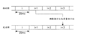
Fig. 2 has shown under conventional art at the frame that receives on the Traffic Channel and has contained time relationship between the transmit frame of reception result of received frame.With reference to Fig. 2, if receiver receives (i+1) frame on Traffic Channel, so, it just sends the reception result of (i+1) frame in (i+3) frame after two frames.Two frame delay occurring is because synchronously send and received frame on travelling carriage, therefore, can not send the reception result of (i+1) received frame in (i+1) transmit frame.In addition, need the time, therefore, can not in (i+2) transmit frame, send the reception result of (i+1) received frame owing to handle (i+1) received frame.In Fig. 2, a frame be 20ms at interval.
Fig. 3 A has shown multiplexer (MUX) and the multichannel multiplexing method that is used for multi-path multiplexing frame reception result indicating bit shown in Figure 1A and 1B in the receiver of operating like that.In Fig. 3 A, on pilot tone and power control bits (PCB) the time division multiplexing Reverse Pilot Channel in CDMA 2000 systems.Fig. 3 B has shown the structure of power control group (PCG).A 20-ms frame comprises 16 PCG, and each PCG contains a pilot tone and a PCB.Can replace PCB with the reception result indicating bit.Each PCB has unique value in corresponding PCG, the speed that fast power is controlled can be up to 800Hz, and the reception result indicating bit has fixed value in a frame.Therefore, base station transmitter utilizes the reception result indicating bit to carry out the slow power control of 50Hz.Hereinafter, the position of indicated horsepower control information or reception result information is called as " control bit " as PCB or reception result indicating bit.In CDMA 2000 systems, because the 20-ms frame comprises the PCG of 16 1.25-ms, each PCG contains unique control bit, so control bit occurs 16 times in a 20-ms frame.A 1.25-ms PCG is divided into 4 0.3125-ms groups, and 384N chip contained in each 0.3125-ms group.Last of 4 groups is the control bit preparation.The rate of spread of supposing 1.2288Mcps is 1.So, 384 mean that number of chips and N are the rates of spread in the group.For example, if the rate of spread is 3, that is to say, is 3.6864Mcps, so, by following formula 384 * 3 chips is distributed to each group:

When reception result indicating bit in conventional art when the control bit, 16 power control bits in frame are configured to represent a reception result value.In other words, the reception result of frame on the Traffic Channel is arranged among 16 PCB.
Fig. 4 A has shown the structure of the frame of the reception result that comprises traditional travelling carriage report.In Fig. 4 A, all the frame reception result indicating bits in frame are configured to identical value, that is to say that they represent the reception result of a received frame.
Refer back to Figure 1B, base station 110b sends to travelling carriage 120b to first and second Traffic Channels, and travelling carriage 120b only reports a channel in frame shown in Figure 4, that is, and and the reception result of first Traffic Channel.
Reception result can be used to allow the transmitted power of base stations control travelling carriage.It is good becoming if reception result is reported, so, the base station command travelling carriage reduces its transmitted power gradually, perhaps conversely so that travelling carriage can be on acceptable quality level received signal.This is the slow power control based on frame that only just can implement when being difficult to carry out in fast power control.Fast power is controlled every frame and is taken place 16 times.First Traffic Channel can be different with second Traffic Channel at aspects such as data rate, code rate and QoS (service quality) requirements.This means,, be necessary the power control of separately realization Traffic Channel owing on characteristic, there are differences between the Traffic Channel.
But,, when the report reception result only limits to a channel, can not control the transmitted power of other channel when as conventional art.
Simultaneously, utilize the fast power of PCB to control the power control that can be used for two Traffic Channels.That is to say that the travelling carriage transmitter sends the PCB that is used for fast power control on each of two Traffic Channels.But if send SCH with DTX (the interrupted transmission) pattern or with variable bit rate, so, it is insecure carrying out fast power control.Under the DTX pattern, can not suitably keep the outer shroud set-point and under variable bit rate, can not satisfy the PCB transmission requirement of rate detection before.
Summary of the invention
Therefore, an object of the present invention is to provide a kind of equipment and method of in mobile communication system, reporting the reception result of current all channels that using.
Another object of the present invention provides a kind of number according to Traffic Channel, distributes the equipment and the method for the frame reception result indicating bit of giving location number that is used for Traffic Channel in the frame.
A further object of the present invention provides a kind of by receiver, in case receive at least two channels, with regard to the position of the reception result of at least two channels of multiplexed indication with by the transmitter effectively equipment and the method for the transmitted power of at least two channels of control.
In order to achieve the above object, the multiplexed transmitter from the base station of receiver in travelling carriage frame reception result indicating bits that receive, at least two Traffic Channels, insert multiplexed frame reception result indicating bit in the pilot signal by turn and the transmission reverse frames.Then, pilot signal is extracted in the base station from reverse frames, and multichannel analysis frames reception result indicating bit and according to the value of frame reception result indicating bit carries out power control to Traffic Channel.
In order to achieve the above object, a kind of operate travelling carriage be reported in to the base station in the frame, in the method for the accepting state of the first information that receives from the base station on first Traffic Channel and second information that on second Traffic Channel, receives from the base station, this method comprises the following steps: the position of the accepting state of indication first and second information is assigned in the time slot of reverse frames; With the transmission reverse frames.
In order to achieve the above object, a kind of base station of operating is to be controlled at the method for the through-put power of Traffic Channel in the frame, wherein this base station sends the first information and send second information on second Traffic Channel on first Traffic Channel, wherein this base station receives the reception result of the first information and second information from travelling carriage, and this method comprises the following steps: to be received in the reverse frames of the accepting state indicating bit of the accepting state indicating bit that contains the first information in several time slots and second information; With according to first and second information, from reverse frames, isolate the accepting state indicating bit and according to first and second information, first and second Traffic Channels are carried out power control.
In order to achieve the above object, a kind of method of operating mobile communication system with the reception result that is reported in the frame that receives at least two Traffic Channels, this method comprise the following steps: to be received in the frame at least two Traffic Channels and are sent in accepting state indicating bit in the time slot of reverse frames, received frame; With receive reverse frames, from reverse frames, extract the accepting state indicating bit of at least two Traffic Channels and, each Traffic Channel carried out power control according to the value of accepting state indicating bit.
In order to achieve the above object, a kind of receive from the base station the frame, in the first information on first Traffic Channel and second information on second Traffic Channel with report the travelling carriage of the reception result of first and second information to the base station, this travelling carriage comprises: first multiplexer is used for the accepting state indicating bit of multiplexed first and second information; With second multiplexer, be used for the multiplexed accepting state indicating bit of first and second information is assigned to successively the time slot of reverse frames, each time slot has an accepting state indicating bit.
In order to achieve the above object, a kind ofly send second information in the frame, on the first information on first Traffic Channel and second Traffic Channel and receive the base station of the reception result of first and second information from travelling carriage to travelling carriage, this base station comprises: first demultiplexer, be used to receive the reverse frames that contains several time slots and from reverse frames, isolate travelling carriage accepting state indicating bits multiplexed, first and second information; With second demultiplexer, be used for multiplexed accepting state indicating bit multichannel is resolved into the accepting state indicating bit of the first information and the accepting state indicating bit of second information.
In order to achieve the above object, a kind of at least two Traffic Channels the mobile communication system of transmit frame, this system comprises: travelling carriage is used for being received in frame and accepting state indicating bits time slot, at least two Traffic Channels that are sent in reverse frames at least two Traffic Channels; And the base station, be used for receiving reverse frames from travelling carriage, extract the accepting state indicating bit of at least two Traffic Channels and, respectively two Traffic Channels are carried out power control from reverse frames according to the value of accepting state indicating bit.
The accompanying drawing summary
In conjunction with the drawings, carry out following detailed description, of the present invention above and other purpose, feature and advantage will be clearer, in the accompanying drawings:
Figure 1A has shown the traditional operation of report frame reception result in mobile communication system;
Figure 1B has shown the another kind of traditional operation of report frame reception result in mobile communication system;
Fig. 1 C has shown according to embodiments of the invention, the operation of report frame reception result in mobile communication system;
Fig. 2 has shown the frame delay that will involve usually when reporting the frame reception result in traditional mobile communication system;
Fig. 3 A has shown multiplexed in traditional receiver of frame reception result indicating bit;
Fig. 3 B has shown the structure of conventional P CG;
Fig. 4 A has shown the structure of the frame that is used for traditional reception result report;
Fig. 4 B has shown the embodiment that is used for according to the frame structure of reception result report of the present invention;
Fig. 4 C has shown another embodiment that is used for according to the frame structure of reception result report of the present invention;
Fig. 4 D has shown the 3rd embodiment that is used for according to the frame structure of reception result report of the present invention;
Fig. 4 E has shown the 4th embodiment that is used for according to the frame structure of reception result report of the present invention;
Fig. 4 F has shown the 5th embodiment that is used for according to the frame structure of reception result report of the present invention;
Fig. 5 is the calcspar that is presented at according to the base station transmitter in the mobile communication system of the present invention;
Fig. 6 A is presented at according in the mobile communication system of the present invention, the partial block diagram of the travelling carriage receiver that links together with the reception of first traffic channel frame;
Fig. 6 B is presented at according in the mobile communication system of the present invention, the partial block diagram of the travelling carriage receiver that links together with the reception of second traffic channel frame;
Fig. 7 A is presented at according in the mobile communication system of the present invention, with the partial block diagram of the embodiment of the generic connection travelling carriage transmitter together of reverse transmit frame;
Fig. 7 B is presented at according in the mobile communication system of the present invention, with the partial block diagram of the embodiment that handles the base station receiver that the reverse frames that receives from the receiver shown in Fig. 7 A links together;
Fig. 8 A is presented at according in the mobile communication system of the present invention, with the partial block diagram of another embodiment of the generic connection travelling carriage transmitter together of reverse transmit frame;
Fig. 8 B has shown the structure that generates reverse transmit frame in the receiver shown in Fig. 8 A;
Fig. 8 C is presented at according in the mobile communication system of the present invention, with the partial block diagram of another embodiment that handles the base station receiver that the reverse frames that receives from the receiver shown in Fig. 8 A links together;
Fig. 9 A is presented at according in the mobile communication system of the present invention, with the partial block diagram of the 3rd embodiment of the generic connection travelling carriage transmitter together of reverse transmit frame;
Fig. 9 B has shown the structure that generates reverse transmit frame in the receiver shown in Fig. 9 A;
Fig. 9 C is presented at according in the mobile communication system of the present invention, with the partial block diagram of the 3rd embodiment that handles the base station receiver that the reverse frames that receives from the receiver shown in Fig. 9 A links together;
Figure 10 A is presented at according in the mobile communication system of the present invention, with the partial block diagram of the 4th embodiment of the generic connection travelling carriage transmitter together of reverse transmit frame; With
Figure 10 B is presented at according in the mobile communication system of the present invention, with the partial block diagram of the 4th embodiment that handles the base station receiver that the reverse frames that receives from the receiver shown in Figure 10 A links together.
Preferred embodiment describes in detail
Hereinafter describe the preferred embodiments of the present invention with reference to the accompanying drawings.In following description, those well-known functions or structure will be described in detail, because otherwise, they will be submerged in feature of the present invention among the unnecessary details.
Fig. 1 C has shown totally how travelling carriage reports reception result according to the present invention.With reference to Fig. 1 C, transmitter (base station) 110c sends first traffic channel frame and second traffic channel frame to receiver (travelling carriage) 120c.Travelling carriage 120c before sending, the reception result of multiplexed first and second traffic channel frame.According to reception result, base station 110c can carry out slow power control or fast power control.This operation also can be applied to Traffic Channel more than other situation of two.
Fig. 4 B has shown the embodiment that is used for according to the frame structure of reception result report of the present invention.If the base station sends first traffic channel frame and second traffic channel frame, the same with conventional method so, travelling carriage before sending, time division multiplexing reverse pilot signal and frame reception result indicating bit.But, because in conventional method, 16 frame reception result indicating bits are formed for the value of a channel reception result in a frame, and in the present invention, preceding 8 control bits are configured to indicate the frame reception result indicating bit of the reception result of first traffic channel frame, be configured to indicate the frame reception result indicating bit of the reception result of second traffic channel frame with back 8 control bits, therefore, the present invention is different with conventional method.Though identical figure place is distributed frame reception result indicating bit as each Traffic Channel,, also can utilize not the frame reception result indicating bit (for example, 10: 6) of isotopic number to represent each Traffic Channel reception result.
Fig. 4 C has shown another embodiment that is used for according to the frame structure of reception result report of the present invention.In Fig. 4 C, the control bit in the reverse frames alternately is designated as the reception result indicating bit of first traffic channel frame and the reception result indicating bit of second traffic channel frame.The odd number control bit is configured to the frame reception result indicating bit of first traffic channel frame and the frame reception result indicating bit that the even number control bit is configured to second traffic channel frame.
When the reception result of multiplexed two or more Traffic Channels, can make many other modifications to the pattern of the frame reception result indicating bit shown in Fig. 4 A and the 4B, and still drop within the scope and spirit of the present invention.
Fig. 4 D has shown the 3rd embodiment that is used for according to the frame structure of reception result report of the present invention.In Fig. 4 D, it is 16 code word that the reception result of traffic channel frame is encoded into length.It is contemplated that out the various different codes of representative reception result.According to the present invention, because code word is defined by reporting the state of first and second Traffic Channels, therefore, they must be mutually orthogonal.Table 1 has shown the exemplary orthogonal code group of the state of indicating first and second Traffic Channels.
(table 1)
| The reception result of first Traffic Channel | The reception result of second Traffic Channel | 16 bit word |
| Good | Good | 0000000000000000 |
| Good | Difference | 0101010101010101 |
| Difference | Good | 0011001100110011 |
| Difference | Difference | 0110011001100110 |
In table 1, it all is good that code word " 0000000000000000 " is represented the reception result of two Traffic Channels.It is good that code word " 0101010101010101 " is represented the reception result of first Traffic Channel, but the reception result of second Traffic Channel is poor.It is poor that code word " 0011001100110011 " is represented the reception result of first Traffic Channel, but the reception result of second Traffic Channel is good.It all is poor that code word " 0110011001100110 " is represented the reception result of two Traffic Channels.In a frame, a code symbol is assigned to each of 16 time slots.As can be seen from Table 1, code word is mutually orthogonal, may have mistake although cause, and receiver can also reduce the reception code word.
Be listed in the only exemplary application of orthogonal code in the table 1.Therefore, as previously mentioned, well behaved any code all is feasible when error correction.In addition, though reception result is become " good " or " difference " by simple classification in table 1,, can be more information, for example, CRC check result and receive energy level and be incorporated in the reception result.
In case receive in the manner described above the frame of coding, just multiply each other in 4 orthogonal codes shown in 16 bit word in the frame and the table 1 each in the base station, and the corresponding reception result of orthogonal code of selection and correlation maximum.For example, if 16 bit word are the most relevant with orthogonal code " 0000000000000000 ", so, the base station just concludes that it all is the first and second good Traffic Channels that travelling carriage receives the quality of reception.
Fig. 4 E has shown the 4th embodiment that is used for according to the frame structure of reception result report of the present invention.
In power control bits being inserted the first professional control bit position, replace the situation of frame reception result indicating bit, because the base station sends first traffic channel frame and second traffic channel frame, with travelling carriage before sending, the time division multiplexing reverse pilot signal and the first and second professional control bits, therefore, the 4th embodiment is identical with above-mentioned the 3rd embodiment.That is to say,, send the power control bits that each has independent values, and, be sent in the frame reception result indicating bit that has only a value in the frame for second Traffic Channel for first Traffic Channel.Base station transmitter 110c can carry out fast power control and to second Traffic Channel, can carry out slow power control with 50Hz first Traffic Channel with 400Hz.
In the frame shown in Fig. 4 E, power control bits quantitatively is identical with frame reception result indicating bit, and is interleaved, and still, obviously, their quantity also can be different because of pattern.And this embodiment also can be applied to Traffic Channel more than other situation of two.
Fig. 4 F has shown the 5th embodiment that is used for the frame structure of reception result report according to of the present invention.In Fig. 4 F, in reverse frames, quantitatively according to 1: 3 pro rate power control bits and frame reception result indicating bit.
Fig. 5 is the calcspar according to base station transmitter of the present invention.With reference to Fig. 5, the first Traffic Channel frame generator 510 generates first traffic channel frame.Multiplier 514 multiply by first channel gain with first traffic channel frame.The second Traffic Channel frame generator 512 generates second traffic channel frame.Multiplier 516 multiply by the second channel gain with second traffic channel frame.Channel gain controller 522 generates the control signal that is used to control the Traffic Channel gain according to the frame reception result from receiver.First gain generator 518 generates first channel gain and second gain generator 520 under the control of controller 522 under the control of channel gain controller 522, generate the second channel gain.First orthogonal code is multiply by in the output of multiplier 514 with multiplier 524 and multiplier 526 multiply by second orthogonal code with the output of multiplier 516. Multiplier 528 and 530 utilizes predetermined PN (pseudo noise) sign indicating number, expands the output of multiplier 524 and 526 respectively.Adder 532 adds multiplier 528 and 530 output is in the same place, and transmission and signal.If multiplier 524 and 526 output added is in the same place, expand with identical PN sign indicating number then, so, can obtain identical result.
In operating process, the first and second Traffic Channel frame generators 510 and 512 generate first and second traffic channel frame respectively.Multiplier 514 multiply by first channel gain that the first channel gain generator 518 generates with first traffic channel frame.Multiplier 516 multiply by the second channel gain that second channel gain generator 520 generates with second traffic channel frame.First and second channel gains are determined according to the reception result of receiver by channel gain generator 522.Multiplier 524 multiply by first orthogonal code and multiplier 526 with first traffic channel frame of gain controlling second traffic channel frame of gain controlling be multiply by second orthogonal code.Multiplier 528 and 530 utilizes predetermined PN sign indicating number to expand the output of multiplier 524 and 526 respectively.Adder 532 is summed into public transmission signal to the output of multiplier 528 and 530.
As mentioned above, channel gain controller 522 is according to the reception result of report, and control channel gains.For this reason, because transmit frame reception result in many code elements of receiver in frame, so need additional parts from the frame that receives from receiver, to extract the code element of the reception result of indicating services channel.These parts are presented among Fig. 7 C, 8C, 9C and the 10B in detail.
If report claims to have received first Traffic Channel under good state, so, slowly reduce the transmitted power of first and second Traffic Channels with identical speed.On the other hand, if report claims to receive first Traffic Channel under the state of difference, so, with slowly the raise transmitted power of first and second Traffic Channels of identical speed.If the reception result of first and second traffic channel frame is identical, so, this operation can not run into any problem.In other words, if the reception result of first traffic channel frame is identical with the reception result of second traffic channel frame, so, reduce gradually or the transmitted power of first and second Traffic Channels that raise with identical speed, and the constant rate that keeps the transmitted power of the transmitted power of second Traffic Channel and first Traffic Channel.But, as in many cases,, and keep the relative speed of transmitted power of second Traffic Channel constant if the reception result difference of these traffic channel frame so, does not wish to control transmitted power.Therefore, if be defined as the different reception results of relevant first and second Traffic Channels of report continuously, so, utilize the change ratio of the second Traffic Channel transmitted power and the first Traffic Channel transmitted power to carry out power control.With regard to the control of power ratio,, so, reduce the transmitted power of first Traffic Channel, and keep the transmitted power difference of second Traffic Channel if the reception result of first traffic channel frame is that the good reception result with second traffic channel frame is poor.In this manner, adjust the transmitted power ratio, till reception result both differences of traffic channel frame.Then, remain unchanged, realize power control, thereby the quality of reception is remained on the acceptable level by the transmitted power that makes Traffic Channel.With the description of receiver power control is described in more detail later on.
Fig. 6 A is in mobile communication system according to the present invention, the partial block diagram of the travelling carriage receiver that links together with the reception of first traffic channel frame.With reference to Fig. 6 A, first traffic channel frame that despreader 610 utilizes the despreading of PN sequence to receive on the forward link.Decoder 612 is used for the orthogonal code decoding PN despread signal of respective channel.Orthogonal code can be that Walsh (Walsh) sign indicating number and channel can be user traffic channel.The CRC of CRC check device 614 verification quadrature decoder signals.Power checker 616 is measured the power of PN despread signal, and definite measurement result is enough or not enough.For example, if the power of PN despread signal, so just thinks that it is enough greater than the reference power level, otherwise, just think that it is not enough.Frame reception result determinant 618 is judged the reception result of first traffic channel frame according to the power measurement result, and exports the frame reception result indicating bit of first traffic channel frame.
Fig. 6 B is in mobile communication system according to the present invention, the partial block diagram of the travelling carriage receiver that links together with the reception of second traffic channel frame.Except having omitted the power checker in Fig. 6 B, the part that receives second traffic channel frame is structurally identical with the first traffic channel frame receiving unit.This is that second traffic channel frame does not then have because first traffic channel frame has comprised power measurement information.Because second traffic channel frame only contains CRC check information, therefore, when not receiving CRC information, with regard to effect, second Traffic Channel has been discharged by void.So frame reception result determinant 626 is judged the reception result of second traffic channel frame, and is exported the frame reception result indicating bit of second traffic channel frame according to the CRC check result who receives from CRC check device 624.
Structurally difference ascribes to first traffic channel frame and compares between the first traffic channel frame receiving unit shown in Fig. 6 A and the second traffic channel frame receiving unit shown in Fig. 6 B, lacks the energy measurement code element in second traffic channel frame.In other words, judge that the reception result of first traffic channel frame needs CRC check and energy measurement, judge that the reception result of second traffic channel frame then only needs CRC check.Should be called as input signal frame though note that the signal in the input despreader 610 and 620 here, a term that is encompassed in the signal that receives on all channels,, for the sake of clarity, also can call first and second traffic channel frame to them.
With reference to Fig. 6 A and 6B, the operation of travelling carriage receiver according to the present invention is described below.First and second traffic channel frame are imposed on the input of despreader 610 and 620 respectively.Despreader 610 and 620 multiply by the PN sign indicating number with first and second traffic channel frame.The PN despread signal that the PN despread signal of despreader 610 is fed to decoder 612 and power checker 616 and despreader 620 is fed to decoder 622.
Frame reception result determinant 618 according to the CRC check result who receives from CRC check device 614 and as shown in table 2, from the result of determination that power checker 616 receives, generate the reception result indicating bit of first traffic channel frame.
(table 2)
| The CRC performance number | Good | Difference |
| Enough | 1 | 1 |
| Inadequately | 1 | 0 |
In table 2,, so, the reception result indicating bit is arranged to " 0 " if the power measurement result is not more than the reference power value and the CRC check result is poor.In other cases, the reception result indicating bit is arranged to " 1 ".
Frame reception result determinant 626 shown in Fig. 6 B generates the reception result indicating bit of second traffic channel frame according to the CRC check result who receives from CRC check device 614.For example, if the CRC check result is good, so, the reception result indicating bit is arranged to " 1 ", the reception that indication is good otherwise, is arranged to it " 0 ", the reception of indication difference.
A frame must be inserted in the reception result position of first and second traffic channel frame before sending.The embodiment that forms the structure of the frame that comprises frame reception result indicating bit in the receiver is presented among Fig. 7 A, 8A, 9A and the 10A.
From now on, the code element of extracting the representative frame reception result to transmit frame reception result indicating bit in the code element of a frame with from frame is described.
At first be given in the embodiment of the equipment of the reception result of report Traffic Channel in the frame in conjunction with Fig. 7 A, 8A, 9A and 10A.
First embodiment
Fig. 7 A is the calcspar of the embodiment of the reverse transmission frame generation apparatus in travelling carriage according to the present invention.With reference to Fig. 7 A, the frame reception result indicating bit of multiplexed first and second traffic channel frame that receive from the structure shown in Fig. 6 A and the 6B of first multiplexer (MUX1) 710.MUX1 710 can export the successive frames reception result indicating bit of first traffic channel frame earlier, and then exports the frame reception result indicating bit of second traffic channel frame.Perhaps, MUX1 710 exports the frame reception result indicating bit of first and second traffic channel frame by turn.Second multiplexer (MUX2) 712 is to insert a reception result indicating bit a kind of like this mode among each PCG, time division multiplexed pilots signal and frame reception result indicating bit.Multiplier 714 utilizes the PN sign indicating number that consults between base station and the travelling carriage, the output of expansion MUX2 712, and send spread signal as reverse transmit frame.MUX1 710 and MUX2 712 can be merged into equivalence 3 paths (3-way) MUX.
In operating process, MUX1 710 multiplexed frame reception result indicating bits from frame reception result determinant 618 shown in Fig. 6 A and the 6B and 626 first and second traffic channel frame that receive.According to how controlling MUX1 710, can be with various different modes design multiplex operations.Two kinds of multiplex modes have been described above.They one of be behind the successive frames reception result indicating bit of output first traffic channel frame, export the frame reception result indicating bit of second traffic channel frame successively.Another kind is the frame reception result indicating bit of alternate selection first and second traffic channel frame.Although do not show, need controller to control MUX1 710, this and controller are to provide whole control to receiver, still only provide control irrelevant to MUX1 710 independently.
Fig. 4 B and 4C have shown the embodiment of reverse transmit frame structure.(the frame reception result indicating bit of) first traffic channel frame for example, 8 when selecting the frame reception result indicating bit of second traffic channel frame of predetermined figure then, generates the frame shown in Fig. 4 B when MUX1 710 at first selects predetermined figure.Preceding 8 control bits in the frame are configured to the reception result position of first traffic channel frame, and are identical with the reception result position of second traffic channel frame with back 8 control bits.On the other hand, when MUX1 710 alternate selection first and second traffic channel frame, generate the frame shown in Fig. 4 C.As mentioned above, can form the reverse transmit frame pattern of various differences according to how controlling MUX1710.
Second embodiment
Fig. 8 A is the calcspar of another embodiment of the reverse transmission frame generation apparatus in travelling carriage according to the present invention.With reference to Fig. 8 A, the frame reception result indicating bit of multiplexed first and second traffic channel frame that receive from the structure shown in Fig. 6 A and the 6B of MUX1 810.In order to modulate, multiplier 812 multiply by first orthogonal code with multiplexed frame reception result indicating bit.In order to modulate, multiplier 814 multiply by predetermined orthogonal code (orthogonal code #0, W with pilot signal
0).Adder 816 is added together the pilot signal of the frame reception result indicating bit of modulation and modulation.Multiplier 818 utilizes the output signal of predetermined PN sign indicating number expansion adder 816, and sends oppositely transmit frame of PN spread signal conduct.This embodiment is characterised in that, new Code Channel (first orthogonal code) is distributed to frame reception result indicating bit.
In operating process, MUX 810 multiplexed frame reception result indicating bits from frame reception result determinant 618 shown in Fig. 6 A and the 6B and 626 first and second traffic channel frame that receive.With top described the same in conjunction with Fig. 7 A, according to how controlling MUX 810, can be with various different modes design multiplex operations.Multiplier 812 is by multiplying each other them, with the multiplexed frame reception result indicating bit of first orthogonal code modulation.Modulation has caused channelizing.Simultaneously, multiplier 814 is by multiplying each other them, with typical pilot signal orthogonal code W
0The modulated pilots signal.Adder 816 is added together from multiplier 812 and 814 modulation signals that receive.Can think, the multiplying each other of quadrature spread signal, addition is exactly that the sign indicating number of frame reception result indicating bit and pilot signal is multiplexed then.Multiplier 818 signal times that sign indicating number is multiplexed is with the PN sign indicating number, and sends the PN spread signal as reverse transmit frame.
Oppositely transmit frame is presented among Fig. 8 B.In reverse transmit frame, with the corresponding Code Channel of first orthogonal code on transmit frame reception result indicating bit and with W
0Pilot signal transmitted on the corresponding Code Channel.Here, be the first half that first traffic channel frame is distributed frame reception result indicating bit, be second traffic channel frame distribute frame reception result indicating bit back half.
The 3rd embodiment
Fig. 9 A is the calcspar of the 3rd embodiment of the reverse transmission frame generation apparatus in travelling carriage according to the present invention.With reference to Fig. 9 A, MUX1 910 time division multiplexings are from the frame reception result indicating bit and the first reverse traffic channel frame data of first traffic channel frame of the reception of the structure shown in Fig. 6 A.The MUX2912 time division multiplexing is from the frame reception result indicating bit and the second reverse traffic channel frame data of second traffic channel frame of the reception of the structure shown in Fig. 6 B.Multiplier 914 is by multiplying each other them, with the multiplex signal of first orthogonal code modulation from MUX1 910 receptions.Multiplier 916 is by multiplying each other them, with the multiplex signal of second orthogonal code modulation from MUX2 912 receptions.Multiplier 918 is by multiplying each other them, with predetermined orthogonal code (orthogonal code #0, W
0) the modulated pilots signal.Adder 920 is added together the output signal of multiplier 914,916 and 918.Multiplier 922 will be with on duty with predetermined PN sign indicating number, and sends the PC spread signal as reverse transmit frame.
In operating process, MUX1 910 time division multiplexings are from the frame reception result indicating bit and the first reverse traffic channel frame data of first traffic channel frame of 618 receptions of the frame reception result determinant shown in Fig. 6 A.MUX2 912 time division multiplexings are from the frame reception result indicating bit and the second reverse traffic channel frame data of second traffic channel frame of 626 receptions of the frame reception result determinant shown in Fig. 6 B.Can form various multiplex operation according to the method for control MUX1 910 and MUX2 912.Multiplier 914 is by multiplying each other them, with the multiplex signal of first orthogonal code modulation from MUX1 910 receptions.Multiplier 916 is by multiplying each other them, with the multiplex signal of second orthogonal code modulation from MUX2 912 receptions.Multiplier 918 is used W by they are multiplied each other
0The modulated pilots signal.Adder 920 is added together the output signal of multiplier 914,916 and 918.Can think, the multiplying each other of quadrature spread signal, addition is exactly that the sign indicating number of frame reception result indicating bit and pilot signal is multiplexed then.Multiplier 922 signal times that sign indicating number is multiplexed is with the predetermined PN sign indicating number of sign base station, and sends the PC spread signal as reverse transmit frame.
Oppositely transmit frame is presented among Fig. 9 B.In reverse transmit frame, with the corresponding Code Channel of first orthogonal code on send the frame reception result indicating bit and the first reverse traffic channel data of first traffic channel frame, with the corresponding Code Channel of second orthogonal code on send the frame reception result indicating bit of second traffic channel frame and the second reverse traffic channel data and with W
0Pilot signal transmitted on the corresponding Code Channel.
The 4th embodiment
Figure 10 A is the calcspar of the 4th embodiment of the reverse transmission frame generation apparatus in travelling carriage according to the present invention.With reference to Figure 10 A, MUX10 1010 alternately exports from the frame reception result indicating bit of second traffic channel frame of the reception of the structure shown in Fig. 6 B and the PCB of first Traffic Channel.Multiplex signal and pilot signal that MUX2 1012 time division multiplexings receive from MUX1 1010 are so that insert a PCB or a frame reception result indicating bit among each PCG.Multiplier 1014 utilizes the predetermined PN sign indicating number that consults between transmitter and the receiver, the multiplex signal that expansion receives from MUX2 1012, and output PN spread signal is as reverse transmit frame.MUX1 1010 and MUX2 1012 can be merged into an equivalence 3 path MUX, in these equivalent 3 path MUX, PCB and frame reception result indicating bit are alternately inserted in the pilot signal.
In operating process, the frame reception result indicating bit of multiplexed second traffic channel frame that receives from the frame reception result determinant shown in the 6B of MUX1 1010 and the PCB of first Traffic Channel.According to the MUX1 control method, can form various multiplex operation.In this embodiment, MUX1 1010 alternate selection PCB and frame reception result indicating bit.
Although do not show, need controller to control MUX1 1010, this and controller provide whole control to receiver, still only provide control irrelevant to MUX1 1010 independently.
Oppositely transmit frame is presented among Fig. 4 E.By the PCB of alternate selection first Traffic Channel in MUX1 1010 and the frame reception result indicating bit of second traffic channel frame, generate reverse transmit frame.The frame reception result indicating bit interleaved of the PCB of 8 first Traffic Channels and 9 second traffic channel frame in frame.
Though PCB quantitatively is identical (8: 8) with frame reception result indicating bit, and mutual interleaved,, also can on quantity and pattern, differently distribute them.Turn back to Fig. 4 F, quantitatively according to 1: 3 pro rate PCB and frame reception result indicating bit.This embodiment also can be applied to Traffic Channel more than two situation be the first Traffic Channel transmit frame reception result indicating bit and be the situation that second Traffic Channel sends PCB.
The hypothesis that contains CRC information according to second traffic channel frame has been described first to fourth embodiment according to the reverse transmission frame generation apparatus in the travelling carriage of the present invention above.Owing in second traffic channel frame, lack aforesaid energy measurement code element, therefore,, just can not obtain the frame reception result indicating bit of second Traffic Channel if discharge.In this case, do not need to send the reception result of second traffic channel frame.Therefore, the same with the conventional method of the reception result that sends first traffic channel frame, in a frame, 16 control bits are distributed to the frame reception result indicating bit of first Traffic Channel.
Now,, be given in detail, be used to handle the description of embodiment of the equipment of the reverse frames that receives from receiver according in the transmitter of the present invention with reference to Fig. 7 C, 8C, 9C and 10B.
First embodiment
Fig. 7 C be according to of the present invention, with the travelling carriage shown in Fig. 7 A in the calcspar of embodiment of transmitter input reverse frames receiver that link together, in the base station.With reference to Fig. 7 C, multiplier 716 utilize be used in receiver in identical PN sign indicating number despreading import reverse frames.Reverse frames is in the form shown in Fig. 4 B.Second demultiplexer (DEMUX2) 718 resolves into pilot signal and multi-path multiplexing frame reception result indicating bit to the despread signal time-division multiplex.First demultiplexer (DEMUX1) 720 resolves into the frame reception result indicating bit of first Traffic Channel and the frame reception result indicating bit of second Traffic Channel to the multi-path multiplexing frame reception result indicating bit multichannel of separating.DEMUX1 720 and DEMUX2 718 can be merged into equivalent 3 path DEMUX.
In operating process, being in the input that reverse frames under the form shown in Fig. 4 B imposes on multiplier 716.Multiplier 716 is used in the PN sign indicating number despreading input reverse frames in the receiver by they are multiplied each other.DEMUX2 718 time-division multiplexes decompose despread signal.Time-division multiplex decomposes to refer to isolates pilot signal from despread signal, that is, in input signal, extracting with the position is the processing that the multi-path multiplexing frame reception result indicating bit of first and second Traffic Channels in the pilot signal is inserted on the basis.By control DEMUX2 718, when scheduled time slot finishes, multi-path multiplexing frame reception result indicating bit outputed to its output, and pilot signal is outputed to other output, just can accomplish this point.Can change the period of extracting with the position frame reception result indicating bit that is the basis insertion according to design.For example, if the time interval of a PCG is 1.25ms, so, a period is 0.0694ms (1.25ms is divided by 18).Therefore, output pilot signal in (1.25ms-0.0694ms) then, is extracted frame reception result indicating bit in all the other periods of about 0.0694ms.
The last frame reception result indicating bit of first and second Traffic Channels is used to control the gain of first and second Traffic Channels, and this is well-known, therefore, omits and does not state.
The reverse frames that according to the reverse frames treatment facility of first embodiment of the invention the successive frames reception result indicating bit of second Traffic Channel wherein is connected on after the successive frames reception result indicating bit of first Traffic Channel is operated.By control DEMUX1 720, come the frame reception result indicating bit of alternate selection first and second Traffic Channels to output to its different outputs, also can operate the reverse frames of the successive frames reception result indicating bit interleaved of the successive frames reception result indicating bit of first Traffic Channel wherein and second Traffic Channel.Such reverse frames is presented among Fig. 4 C.
Second embodiment
Fig. 8 C is the calcspar according to another embodiment of of the present invention, reverse frames receiver that link together with the transmitter of travelling carriage shown in Fig. 8 A, in the base station.With reference to Fig. 8 C, multiplier 820 utilizations are imported reverse frames with the identical PN sign indicating number despreading in being used in receiver.Reverse frames is in the form shown in Fig. 8 B.Multiplier 822 utilizes the first orthogonal code demodulation multi-path multiplexing frame reception result indicating bit identical with the orthogonal code that is used to modulate in receiver.Multiplier 822 utilizes orthogonal code #0, W
0Demodulated pilot signal.DEMUX 826 resolves into the frame reception result indicating bit of first Traffic Channel and the frame reception result indicating bit of second Traffic Channel to multi-path multiplexing frame reception result indicating bit multichannel.Multichannel decompose must be corresponding in the receiver multiplexed.
In operating process, being in the input that reverse frames under the form shown in Fig. 8 B imposes on multiplier 820.Multiplier 820 is by multiplying each other them, utilize be used in receiver in identical PN sign indicating number despreading reverse frames.Multiplier 824 multiply by W to the despreading reverse frames
0Thereby, remove frame reception result indicating bit with the modulation of different orthogonal sign indicating number, and demodulated pilot signal.Multiplier 822 multiply by first orthogonal code to the reverse frames of despreading, thus the pilot signal of removing, and demodulated frames reception result indicating bit.DEMUX 826 isolates the frame reception result indicating bit of first and second Traffic Channels from the output of multiplier 822.
The last frame reception result indicating bit of first and second Traffic Channels is used to control the gain of first and second Traffic Channels, and this is well-known, therefore, omits and does not state.
The 3rd embodiment
Fig. 9 C be according to of the present invention, with the travelling carriage shown in Fig. 9 A in the calcspar of the 3rd embodiment of transmitter reverse frames receiver that link together, in the base station.With reference to Fig. 9 C, multiplier 924 utilizations are imported reverse frames with the identical PN sign indicating number despreading in being used in receiver.Reverse frames is in the form shown in Fig. 9 B.Multiplier 926 is by multiply by despread signal first orthogonal code, and demodulation comprises the frame reception result indicating bit of first Traffic Channel and the multiplex signal of the first reverse traffic channel frame data.Multiplier 928 is by multiply by despread signal second orthogonal code, and demodulation comprises the frame reception result indicating bit of second Traffic Channel and the multiplex signal of the second reverse traffic channel frame data.First and second orthogonal codes are identical with those orthogonal codes that are used to modulate in receiver.Multiplier 930 utilizes orthogonal code #0, W
0Demodulated pilot signal.DEMUX 932 resolves into the output multichannel of multiplier 926 the frame reception result indicating bit and the first reverse traffic channel frame data of first Traffic Channel.DEMUX 934 resolves into the output multichannel of multiplier 928 the frame reception result indicating bit and the second reverse traffic channel frame data of second Traffic Channel.Multichannel decompose must be corresponding in the receiver multiplexed.
In operating process, being in the input that reverse frames under the form shown in Fig. 9 B imposes on multiplier 924.Multiplier 924 is by multiplying each other them, utilize be used in receiver in identical PN sign indicating number despreading reverse frames.Multiplier 930 multiply by W with the reverse frames of despreading
0Thereby, remove other signal with the modulation of different orthogonal sign indicating number, and demodulated pilot signal.Multiplier 926 multiply by first orthogonal code to the despreading reverse frames, thereby only demodulation comprises the frame reception result indicating bit of first Traffic Channel and the multiplex signal of the first reverse traffic channel frame data.Multiplier 928 multiply by second orthogonal code to the despreading reverse frames, thereby only demodulation comprises the frame reception result indicating bit of second Traffic Channel and the multiplex signal of the second reverse traffic channel frame data.DEMUX1 932 isolates the frame reception result indicating bit and the first reverse traffic channel frame data of first Traffic Channel from the output of multiplier 926.DEMUX2 934 isolates the frame reception result indicating bit and the second reverse traffic channel frame data of second Traffic Channel from the output of multiplier 928.
The last frame reception result indicating bit of first and second Traffic Channels is used to control the gain of first and second Traffic Channels, and this is well-known, therefore, omits and does not state.
The 4th embodiment
Figure 10 B is the calcspar according to the 4th embodiment of of the present invention, reverse frames receiver that link together with the transmitter of travelling carriage shown in Figure 10 A, in the base station.With reference to Figure 10 B, multiplier 1016 utilizations are imported reverse frames with the identical PN sign indicating number despreading in being used in receiver.Reverse frames is in the form shown in Fig. 4 E.DEMUX2 1018 resolves into pilot signal and multiplexed Traffic Channel control bit to the despread signal time-division multiplex.DEMUX1 1020 multichannels are decomposed the PCB of first Traffic Channel and the frame reception result indicating bit of second Traffic Channel.
In operating process, being in the input that reverse frames under the form shown in Fig. 4 E imposes on multiplier 1016.Multiplier 1016 is by multiplying each other them, utilize be used in receiver in identical PN sign indicating number despreading reverse frames.By control DEMUX2 1018, when scheduled time slot finishes, multi-path multiplexing frame reception result indicating bit outputed to its output, and pilot signal is outputed to other output, it is multi-path multiplexing frame reception result indicating bit and the pilot signal that insert on the basis that DEMUX2 1018 isolates from despread signal with the position.Can change the period of extracting with the position frame reception result indicating bit that is the basis insertion according to design.
The frame reception result indicating bit of the PCB of first Traffic Channel and second Traffic Channel is used to control the gain of first and second Traffic Channels, though PCB can have different value with the difference of PCG, but in a frame, each of frame reception result indicating bit but has identical value.
According to the present invention, the travelling carriage receiver that receives two or more channels from base station transmitter is before sending, and the frame reception result indicating bit of multiplexer channel is so that base station transmitter can be according to its transmitted power of frame reception result indicating bit control.In addition, the travelling carriage receiver can be before sending, according to channel multi-path multiplexing frame reception result indicating bit and PCB, so that slow power control and fast power control can be carried out to the different business channel simultaneously in the base station.
Though by reference some preferred embodiment of the present invention, the present invention is illustrated and describes, but those of ordinary skill in the art should be understood that, can do various changes to it in the form and details, and the spirit and scope of the present invention that do not depart from appended claims and limited.
Claims (23)
1. operate travelling carriage to be reported in the method for the accepting state of the first information that receives from the base station on first Traffic Channel and second information that receives from the base station on second Traffic Channel to the base station in a frame for one kind, this method comprises the following steps:
The position of the accepting state of indication first and second information is assigned in a plurality of time slots of a reverse frames; With
Send reverse frames.
2. method according to claim 1, wherein, in the time slot of interleaved, the accepting state indicating bit interleaved of the accepting state indicating bit of the first information and second information.
3. method according to claim 1, wherein, in the front of reverse frames in succession in the time slot position of first predetermined figure be configured to the accepting state indicating bit of the first information and in the back of reverse frames in succession in the time slot position of second predetermined figure be configured to the accepting state indicating bit of second information.
4. method according to claim 1, wherein, the accepting state indicating bit of first and second information is to be the reception result indicating bit that power control is carried out on the basis with the frame.
5. method according to claim 1, wherein, the accepting state indicating bit of the first information is to be that the power control bits of power control is carried out on the basis and the accepting state indicating bit of second information is to be the reception result indicating bit that power control is carried out on the basis with the frame with the time slot.
6. method according to claim 1, wherein, reverse frames is a pilot channel frame.
7. operate the base station in a frame, to control the method for the through-put power of a plurality of Traffic Channels for one kind, wherein this base station sends the first information and send second information on second Traffic Channel on first Traffic Channel, wherein this base station is from the reception result of the travelling carriage reception first information and second information, and this method comprises the following steps:
Receive reverse frames, described reverse frames contains the accepting state indicating bit of the first information and the accepting state indicating bit of second information in several time slots; With
According to first and second information, from reverse frames, isolate the accepting state indicating bit and, first and second Traffic Channels are carried out power control according to first and second information.
8. method of operating mobile communication system with the reception result that is reported in the frame that receives at least two Traffic Channels, this method comprises the following steps:
Be received in the frame at least two Traffic Channels and in a plurality of time slots of a reverse frames, send the accepting state indicating bit of the frame that is received; With
Receive reverse frames, from reverse frames, extract the accepting state indicating bit of at least two Traffic Channels and, each Traffic Channel is carried out power control according to the value of accepting state indicating bit.
9. method according to claim 8, wherein, the reverse frames forwarding step comprises the following steps:
The accepting state indicating bit of multiplexed at least two Traffic Channels; With
The accepting state indicating bit is assigned to successively in the time slot of reverse frames, each time slot contains an accepting state indicating bit.
10. method according to claim 9, wherein, extraction step comprises the following steps:
From reverse frames, be extracted in and send multiplexed accepting state indicating bit before; With
Multiplexed accepting state indicating bit multichannel is resolved into the accepting state indicating bit of each Traffic Channel.
11. one kind is received in the first information on first Traffic Channel and second information on second Traffic Channel and reports the travelling carriage of the reception result of first and second information to the base station from the base station in a frame, this travelling carriage comprises:
First multiplexer is used for the accepting state indicating bit of multiplexed first and second information; With
Second multiplexer is used for the multiplexed accepting state indicating bit of first and second information is assigned to successively a plurality of time slots of a reverse frames, and each time slot has an accepting state indicating bit.
12. travelling carriage according to claim 11, wherein, first multiplexer is alternately exported the accepting state indicating bit of the first information, and the accepting state indicating bit of second information.
13. travelling carriage according to claim 12, wherein, first multiplexer distributes the accepting state indicating bit of the first information of first predetermined figure, each position is assigned to the front in succession in the time slot, accepting state indicating bit with second information of distributing second predetermined figure, each position is assigned to the back in succession in the time slot, and the back time slot is connected on the back of the front time slot that is used for the first information.
14. travelling carriage according to claim 11, wherein,
Described first multiplexer is configured for the described accepting state indicating bit and the pilot signal of multiplexed first and second information in each frame; With
Described travelling carriage also comprises:
Expander is used to expand described multiplex signal.
15. travelling carriage according to claim 11, wherein, the accepting state indicating bit of first and second information is to be the reception result indicating bit that power control is carried out on the basis with the frame.
16. travelling carriage according to claim 11, wherein, the accepting state indicating bit of the first information
Be to be that the power control bits of power control is carried out on the basis and the accepting state indicating bit of second information is to be the reception result indicating bit that power control is carried out on the basis with the frame with the time slot.
17. travelling carriage according to claim 11, wherein, reverse frames is a pilot channel frame.
18. one kind is sent in the first information on first Traffic Channel and second information on second Traffic Channel and receives the base station of the reception result of first and second information from travelling carriage to travelling carriage in a frame, this base station comprises:
First demultiplexer is used to receive the reverse frames that contains several time slots and isolates travelling carriage accepting state indicating bits multiplexed, first and second information from reverse frames; With
Second demultiplexer is used for multiplexed accepting state indicating bit multichannel is resolved into the accepting state indicating bit of the first information and the accepting state indicating bit of second information.
19. base station according to claim 18, wherein, in the interleaved time slot of reverse frames, the multiplexed accepting state indicating bit interleaved of first and second information.
20. base station according to claim 19, wherein, the front that the multiplexed accepting state indicating bit of the first information is arranged in reverse frames is arranged in the back in succession in the time slot that is connected on time slot back, front in succession in the time slot and the multiplexed accepting state indicating bit of second information.
21. the mobile communication system of a transmit frame at least two Traffic Channels, this system comprises:
Travelling carriage is used for being received in the frame at least two Traffic Channels and sends the accepting state indicating bit of at least two Traffic Channels at a plurality of time slots of a reverse frames; With
The base station is used for receiving reverse frames from travelling carriage, extracts the accepting state indicating bit of at least two Traffic Channels and according to the value of accepting state indicating bit, respectively two Traffic Channels is carried out power control from reverse frames.
22. mobile communication system according to claim 21, wherein, travelling carriage comprises:
First multiplexer is used for the accepting state indicating bit of multiplexed at least two Traffic Channels; With
Second multiplexer is used for the accepting state indicating bit is assigned to successively the time slot of reverse frames, and each time slot contains an accepting state indicating bit.
23. mobile communication system according to claim 21, wherein, the base station comprises:
First demultiplexer is used to receive reverse frames and isolates the multiplexed accepting state indicating bit of receiver from reverse frames; With
Second demultiplexer is used for multiplexed accepting state indicating bit multichannel is resolved into the accepting state indicating bit of each Traffic Channel.
Applications Claiming Priority (4)
| Application Number | Priority Date | Filing Date | Title |
|---|---|---|---|
| KR1019990050768A KR20010046841A (en) | 1999-11-16 | 1999-11-16 | Apparatus for reporting result of frame reception and method thereof in mobile communication system |
| KR1999/50768 | 1999-11-16 | ||
| KR1020000000728A KR20010068691A (en) | 2000-01-07 | 2000-01-07 | Apparatus and method for controlling power in mobile communication system |
| KR2000/728 | 2000-01-07 |
Publications (2)
| Publication Number | Publication Date |
|---|---|
| CN1390396A CN1390396A (en) | 2003-01-08 |
| CN100435491C true CN100435491C (en) | 2008-11-19 |
Family
ID=26636326
Family Applications (1)
| Application Number | Title | Priority Date | Filing Date |
|---|---|---|---|
| CNB008157243A Expired - Lifetime CN100435491C (en) | 1999-11-16 | 2000-11-16 | Power controlling apparatus and method in mobile communication system |
Country Status (10)
| Country | Link |
|---|---|
| US (2) | US6810264B1 (en) |
| EP (1) | EP1234384B1 (en) |
| JP (1) | JP4098524B2 (en) |
| KR (1) | KR100459551B1 (en) |
| CN (1) | CN100435491C (en) |
| AU (1) | AU767199B2 (en) |
| BR (1) | BR0015608A (en) |
| CA (1) | CA2391631C (en) |
| DE (1) | DE60021281T2 (en) |
| WO (1) | WO2001037443A1 (en) |
Families Citing this family (57)
| Publication number | Priority date | Publication date | Assignee | Title |
|---|---|---|---|---|
| WO2001037443A1 (en) * | 1999-11-16 | 2001-05-25 | Samsung Electronics Co., Ltd | Power controlling apparatus and method in mobile communication system |
| KR100459564B1 (en) * | 2000-06-21 | 2004-12-03 | 삼성전자주식회사 | apparatus and method for reporting service load to mobile station in mobile communication system |
| EP1391059B1 (en) * | 2001-05-31 | 2009-01-21 | Magnolia Broadband, Inc. | Communication device with smart antenna using a quality-indication signal |
| US8249187B2 (en) | 2002-05-09 | 2012-08-21 | Google Inc. | System, method and apparatus for mobile transmit diversity using symmetric phase difference |
| NL1018463C2 (en) * | 2001-07-04 | 2003-01-08 | Marc Van Oldenborgh | Method, layout and software for digitally inverse multiplexing. |
| US7672685B2 (en) * | 2001-10-17 | 2010-03-02 | Sony Corporation | Transmitter and transmission control method, and receiver and reception control method |
| US20030152102A1 (en) * | 2002-02-12 | 2003-08-14 | William Morgan | Method and apparatus for predicting a frame type |
| EP1385275B1 (en) * | 2002-07-23 | 2012-05-30 | NTT DoCoMo, Inc. | Method of deciding transmit power level in a mobile communications system |
| US7505741B2 (en) * | 2002-11-01 | 2009-03-17 | Magnolia Broadband Inc. | Processing diversity signals using a delay |
| US7299402B2 (en) | 2003-02-14 | 2007-11-20 | Telefonaktiebolaget Lm Ericsson (Publ) | Power control for reverse packet data channel in CDMA systems |
| US7092731B2 (en) * | 2003-03-06 | 2006-08-15 | Lucent Technologies Inc. | Method for improving capacity of a reverse link channel in a wireless network |
| US8254358B2 (en) | 2003-03-06 | 2012-08-28 | Ericsson Ab | Communicating a broadcast message to change data rates of mobile stations |
| US7418067B1 (en) | 2003-04-14 | 2008-08-26 | Magnolia Broadband Inc. | Processing diversity signals at a mobile device using phase adjustments |
| JP4367044B2 (en) * | 2003-07-23 | 2009-11-18 | 日本電気株式会社 | Communication system and transmission power control method |
| KR20050031549A (en) * | 2003-09-30 | 2005-04-06 | 유티스타콤코리아 유한회사 | Power control method of external circuit and lock out circuit for reverse data service in cdma2000 system |
| UA83256C2 (en) * | 2003-10-02 | 2008-06-25 | Квелкомм Инкорпорэйтед | Systems and methods for communication control data for multiple data channels using a single control channel (variants) |
| US7430430B2 (en) * | 2003-12-16 | 2008-09-30 | Magnolia Broadband Inc. | Adjusting a signal at a diversity system |
| US7272359B2 (en) * | 2004-01-26 | 2007-09-18 | Magnolia Broadband Inc. | Communicating signals according to a quality indicator using multiple antenna elements |
| US7558591B2 (en) * | 2004-10-12 | 2009-07-07 | Magnolia Broadband Inc. | Determining a power control group boundary of a power control group |
| US7515877B2 (en) * | 2004-11-04 | 2009-04-07 | Magnolia Broadband Inc. | Communicating signals according to a quality indicator and a time boundary indicator |
| US20070066232A1 (en) | 2005-09-22 | 2007-03-22 | Black Peter J | Pilot grouping and route protocols in multi-carrier communication systems |
| US8150408B2 (en) * | 2005-03-08 | 2012-04-03 | Qualcomm Incorporated | Pilot grouping and set management in multi-carrier communication systems |
| US8693383B2 (en) * | 2005-03-29 | 2014-04-08 | Qualcomm Incorporated | Method and apparatus for high rate data transmission in wireless communication |
| KR100703303B1 (en) * | 2005-04-28 | 2007-04-03 | 삼성전자주식회사 | Method of requesting allocation of uplink resources for extended real-time polling service in a wireless communication system |
| US20060267983A1 (en) * | 2005-05-24 | 2006-11-30 | Magnolia Broadband Inc. | Modifying a signal by adjusting the phase and amplitude of the signal |
| US7616930B2 (en) * | 2005-05-24 | 2009-11-10 | Magnolia Broadband Inc. | Determining a phase adjustment in accordance with power trends |
| US7783267B1 (en) | 2005-06-23 | 2010-08-24 | Magnolia Broadband Inc. | Modifying a signal in response to quality indicator availability |
| US7633905B1 (en) | 2005-09-02 | 2009-12-15 | Magnolia Broadband Inc. | Calibrating a transmit diversity communication device |
| US7835702B1 (en) | 2005-09-15 | 2010-11-16 | Magnolia Broadband Inc. | Calculating a diversity parameter adjustment according to previously applied diversity parameter adjustments |
| US7746946B2 (en) * | 2005-10-10 | 2010-06-29 | Magnolia Broadband Inc. | Performing a scan of diversity parameter differences |
| US7630445B1 (en) | 2005-10-25 | 2009-12-08 | Magnolia Broadband Inc. | Establishing slot boundaries of slots of a diversity control feedback signal |
| US7796717B2 (en) * | 2005-11-02 | 2010-09-14 | Magnolia Brandband Inc. | Modifying a signal according to a diversity parameter adjustment |
| US7965987B2 (en) * | 2005-11-03 | 2011-06-21 | Magnolia Broadband Inc. | Amplifying a transmit signal using a fractional power amplifier |
| US20070177544A1 (en) * | 2006-01-27 | 2007-08-02 | Dongzhe Cui | Using the repetition of an erasure indicator bit to enhance a power control command during handoff |
| US7949069B2 (en) * | 2006-10-26 | 2011-05-24 | Magnolia Broadband Inc. | Method, system and apparatus for applying hybrid ARQ to the control of transmit diversity |
| US8150441B2 (en) | 2006-11-06 | 2012-04-03 | Magnolia Broadband Inc. | Modifying a signal by controlling transmit diversity parameters |
| US8199735B2 (en) | 2006-12-12 | 2012-06-12 | Google Inc. | Method, system and apparatus for the control of transmit diversity |
| US7663545B2 (en) * | 2006-12-26 | 2010-02-16 | Magnolia Broadband Inc. | Method, system and apparatus for determining antenna weighting for transmit diversity |
| US8027374B2 (en) * | 2006-12-27 | 2011-09-27 | Magnolia Broadband Inc. | Method, system and apparatus for transmit diversity control |
| US20080160990A1 (en) * | 2006-12-29 | 2008-07-03 | Yair Karmi | System, method and apparatus for identification of power control using reverse rate indication |
| US7869535B2 (en) * | 2007-02-28 | 2011-01-11 | Magnolia Broadband Inc. | Method, system and apparatus for phase control of transmit diversity signals |
| US7991365B2 (en) * | 2007-03-01 | 2011-08-02 | Magnolia Broadband Inc. | Method, system and apparatus for estimation of propagation path variability of a transmit diversity channel |
| US20080227414A1 (en) | 2007-03-01 | 2008-09-18 | Yair Karmi | System, method and apparatus for transmit diversity control based on variations in propagation path |
| US8750811B2 (en) * | 2007-03-14 | 2014-06-10 | Google Inc. | Method, apparatus and system for phase difference adjustment in transmit diversity |
| WO2008113022A1 (en) * | 2007-03-14 | 2008-09-18 | Magnolia Broadband Inc. | Method, apparatus and system for providing transmit diversity feedback |
| US8032091B2 (en) * | 2007-03-14 | 2011-10-04 | Magnolia Broadband Inc. | Method, apparatus and system for providing transmit diversity feedback during soft handoff |
| US8699968B2 (en) | 2007-03-14 | 2014-04-15 | Google Inc. | Using multiple and a single feedback for UE uplink beamforming in soft handoff |
| WO2008113038A1 (en) * | 2007-03-15 | 2008-09-18 | Magnolia Broadband Inc. | Method of controlling a transmit diversity device |
| US8036603B2 (en) | 2007-03-15 | 2011-10-11 | Magnolia Broadband Inc. | Method, apparatus and system for providing feedback to a transmit diversity device |
| US8046017B2 (en) * | 2007-03-15 | 2011-10-25 | Magnolia Broadband Inc. | Method and apparatus for random access channel probe initialization using transmit diversity |
| US8032092B2 (en) * | 2007-12-06 | 2011-10-04 | Magnolia Broadband Inc. | System, apparatus and method for introducing antenna pattern variability |
| US8442457B2 (en) * | 2009-09-08 | 2013-05-14 | Google Inc. | System and method for adaptive beamforming for specific absorption rate control |
| US8958757B2 (en) | 2010-05-10 | 2015-02-17 | Google Inc. | System, method and apparatus for mobile transmit diversity using symmetric phase difference |
| CN103210696B (en) | 2010-05-26 | 2016-06-08 | 谷歌公司 | Initialized method and apparatus is detected for using transmitting diversity to carry out RACH |
| US9048913B2 (en) | 2010-07-06 | 2015-06-02 | Google Inc. | Method and apparatus for adaptive control of transmit diversity to provide operating power reduction |
| US8849222B2 (en) | 2011-02-16 | 2014-09-30 | Google Inc. | Method and device for phase adjustment based on closed-loop diversity feedback |
| EP3203665B1 (en) * | 2014-09-30 | 2020-02-12 | Kabushiki Kaisha Toshiba | Integrated circuit for wireless communication, wireless communication terminal, and wireless communication method |
Citations (3)
| Publication number | Priority date | Publication date | Assignee | Title |
|---|---|---|---|---|
| US5559790A (en) * | 1993-07-23 | 1996-09-24 | Hitachi, Ltd. | Spread spectrum communication system and transmission power control method therefor |
| US5752170A (en) * | 1994-10-15 | 1998-05-12 | Nokia Mobile Phones Limited | Transmitters for radio telephone base stations |
| US5812938A (en) * | 1994-07-11 | 1998-09-22 | Qualcomm Incorporated | Reverse link, closed loop power control in a code division multiple access system |
Family Cites Families (19)
| Publication number | Priority date | Publication date | Assignee | Title |
|---|---|---|---|---|
| US5703902A (en) * | 1995-06-16 | 1997-12-30 | Qualcomm Incorporated | Method and apparatus for determining signal strength in a variable data rate system |
| US5893035A (en) * | 1996-09-16 | 1999-04-06 | Qualcomm Incorporated | Centralized forward link power control |
| US5987333A (en) * | 1997-09-30 | 1999-11-16 | Nortel Networks Corporation/Corporation Nortel Networks | Communications power control |
| US6545986B1 (en) * | 1997-12-31 | 2003-04-08 | Verizon Laboratories Inc. | CDMA forward link power control |
| US6181738B1 (en) * | 1998-02-13 | 2001-01-30 | Northern Telecom Limited | Reverse link power control using a frame quality metric |
| JPH11236165A (en) * | 1998-02-23 | 1999-08-31 | Minolta Co Ltd | Image forming apparatus |
| US6249894B1 (en) * | 1998-02-27 | 2001-06-19 | Motorola, Inc. | Method for determining a need to retransmit a message in a communication system |
| US6914889B1 (en) | 1998-12-08 | 2005-07-05 | Lucent Technologies Inc. | Variable rate forward power control for multichannel applications |
| US6148208A (en) * | 1998-12-21 | 2000-11-14 | Motorola, Inc. | Power control within a broad-band communication system |
| US6879577B2 (en) * | 1998-12-31 | 2005-04-12 | Lg Electronics Inc. | Method and apparatus for determining frame quality in mobile communication system |
| US6151328A (en) * | 1998-12-31 | 2000-11-21 | Lg Information & Communications Ltd. | Apparatus and method for controlling power in code division multiple access system |
| US6590873B1 (en) * | 1999-02-05 | 2003-07-08 | Lucent Technologies Inc. | Channel structure for forward link power control |
| US6493329B1 (en) * | 1999-08-23 | 2002-12-10 | Qualcomm Incorporated | Adaptive channel estimation in a wireless communication system |
| JP3660171B2 (en) | 1999-09-22 | 2005-06-15 | 松下電器産業株式会社 | Communication apparatus and communication method |
| WO2001037443A1 (en) * | 1999-11-16 | 2001-05-25 | Samsung Electronics Co., Ltd | Power controlling apparatus and method in mobile communication system |
| US7590095B2 (en) * | 2000-02-14 | 2009-09-15 | Qualcomm Incorporated | Method and apparatus for power control of multiple channels in a wireless communication system |
| US6996069B2 (en) * | 2000-02-22 | 2006-02-07 | Qualcomm, Incorporated | Method and apparatus for controlling transmit power of multiple channels in a CDMA communication system |
| KR100459564B1 (en) * | 2000-06-21 | 2004-12-03 | 삼성전자주식회사 | apparatus and method for reporting service load to mobile station in mobile communication system |
| JP2004297231A (en) * | 2003-03-26 | 2004-10-21 | Nec Corp | Mobile communication system, radio base station apparatus and power control method used for them |
-
2000
- 2000-11-16 WO PCT/KR2000/001311 patent/WO2001037443A1/en active IP Right Grant
- 2000-11-16 DE DE2000621281 patent/DE60021281T2/en not_active Expired - Fee Related
- 2000-11-16 CA CA 2391631 patent/CA2391631C/en not_active Expired - Lifetime
- 2000-11-16 CN CNB008157243A patent/CN100435491C/en not_active Expired - Lifetime
- 2000-11-16 EP EP00981845A patent/EP1234384B1/en not_active Expired - Lifetime
- 2000-11-16 BR BR0015608A patent/BR0015608A/en not_active Application Discontinuation
- 2000-11-16 US US09/714,313 patent/US6810264B1/en not_active Expired - Lifetime
- 2000-11-16 JP JP2001537885A patent/JP4098524B2/en not_active Expired - Lifetime
- 2000-11-16 AU AU18960/01A patent/AU767199B2/en not_active Expired
- 2000-11-16 KR KR10-2002-7006313A patent/KR100459551B1/en active IP Right Grant
-
2004
- 2004-02-04 US US10/771,474 patent/US7657274B2/en not_active Expired - Fee Related
Patent Citations (3)
| Publication number | Priority date | Publication date | Assignee | Title |
|---|---|---|---|---|
| US5559790A (en) * | 1993-07-23 | 1996-09-24 | Hitachi, Ltd. | Spread spectrum communication system and transmission power control method therefor |
| US5812938A (en) * | 1994-07-11 | 1998-09-22 | Qualcomm Incorporated | Reverse link, closed loop power control in a code division multiple access system |
| US5752170A (en) * | 1994-10-15 | 1998-05-12 | Nokia Mobile Phones Limited | Transmitters for radio telephone base stations |
Also Published As
| Publication number | Publication date |
|---|---|
| AU1896001A (en) | 2001-05-30 |
| JP4098524B2 (en) | 2008-06-11 |
| BR0015608A (en) | 2002-07-30 |
| CA2391631C (en) | 2009-10-20 |
| DE60021281T2 (en) | 2005-12-22 |
| KR100459551B1 (en) | 2004-12-03 |
| US20040157635A1 (en) | 2004-08-12 |
| US6810264B1 (en) | 2004-10-26 |
| CA2391631A1 (en) | 2001-05-25 |
| CN1390396A (en) | 2003-01-08 |
| US7657274B2 (en) | 2010-02-02 |
| AU767199B2 (en) | 2003-11-06 |
| DE60021281D1 (en) | 2005-08-18 |
| EP1234384B1 (en) | 2005-07-13 |
| EP1234384A4 (en) | 2003-05-28 |
| EP1234384A1 (en) | 2002-08-28 |
| KR20020050288A (en) | 2002-06-26 |
| JP2003514484A (en) | 2003-04-15 |
| WO2001037443A1 (en) | 2001-05-25 |
Similar Documents
| Publication | Publication Date | Title |
|---|---|---|
| CN100435491C (en) | Power controlling apparatus and method in mobile communication system | |
| EP1114526B2 (en) | Method of identifying information addressed to a user in a communication system, and a communication system | |
| US7286508B2 (en) | Signal format in multi-carrier CDMA transmission system | |
| KR100387057B1 (en) | Method and apparatus for determining reverse data rate in mobile communication system | |
| US5583851A (en) | Mobile communication apparatus having multi-codes allocating function | |
| US6885649B2 (en) | Method of multiuser detection with user equipment | |
| US7782815B2 (en) | Method for transmitting an information of a mobile telecommunication system | |
| US6301289B1 (en) | To a telecommunication system using code division multiple access (CDMA) | |
| US6636554B2 (en) | Transmission method of words representing transmission parameters respectively allocated to mobile stations communicating with base station in mobile communication system | |
| EP1017190A2 (en) | Radio channel multiplex communication method, a mobile unit, and a base station in CDMA mobile communication system | |
| KR20070061925A (en) | Data detection for codes with non-uniform spreading factors | |
| KR100472692B1 (en) | Subscriber unit for CDMA wireless communication system | |
| KR20010046841A (en) | Apparatus for reporting result of frame reception and method thereof in mobile communication system | |
| KR20020000296A (en) | Apparatus and method for using idle skirt in mobile communication system | |
| CA2625425C (en) | Support of multiuser detection in the downlink | |
| Tomita et al. | A multi-rate CDMA system with block-spreading schemes for anti-interference and high frequency efficiency | |
| KR20010068691A (en) | Apparatus and method for controlling power in mobile communication system | |
| JPH1093531A (en) | Code division multiplex communication equipment |
Legal Events
| Date | Code | Title | Description |
|---|---|---|---|
| C06 | Publication | ||
| PB01 | Publication | ||
| C10 | Entry into substantive examination | ||
| SE01 | Entry into force of request for substantive examination | ||
| C14 | Grant of patent or utility model | ||
| GR01 | Patent grant | ||
| CX01 | Expiry of patent term |
Granted publication date: 20081119 |
|
| CX01 | Expiry of patent term |