CN100409908C - Liquid injection system - Google Patents
Liquid injection system Download PDFInfo
- Publication number
- CN100409908C CN100409908C CNB200410086793XA CN200410086793A CN100409908C CN 100409908 C CN100409908 C CN 100409908C CN B200410086793X A CNB200410086793X A CN B200410086793XA CN 200410086793 A CN200410086793 A CN 200410086793A CN 100409908 C CN100409908 C CN 100409908C
- Authority
- CN
- China
- Prior art keywords
- code
- liquid
- injection
- fluid injector
- fluid
- Prior art date
- Legal status (The legal status is an assumption and is not a legal conclusion. Google has not performed a legal analysis and makes no representation as to the accuracy of the status listed.)
- Expired - Fee Related
Links
Images


Classifications
-
- A—HUMAN NECESSITIES
- A61—MEDICAL OR VETERINARY SCIENCE; HYGIENE
- A61M—DEVICES FOR INTRODUCING MEDIA INTO, OR ONTO, THE BODY; DEVICES FOR TRANSDUCING BODY MEDIA OR FOR TAKING MEDIA FROM THE BODY; DEVICES FOR PRODUCING OR ENDING SLEEP OR STUPOR
- A61M5/00—Devices for bringing media into the body in a subcutaneous, intra-vascular or intramuscular way; Accessories therefor, e.g. filling or cleaning devices, arm-rests
- A61M5/14—Infusion devices, e.g. infusing by gravity; Blood infusion; Accessories therefor
- A61M5/142—Pressure infusion, e.g. using pumps
- A61M5/145—Pressure infusion, e.g. using pumps using pressurised reservoirs, e.g. pressurised by means of pistons
- A61M5/1452—Pressure infusion, e.g. using pumps using pressurised reservoirs, e.g. pressurised by means of pistons pressurised by means of pistons
- A61M5/1456—Pressure infusion, e.g. using pumps using pressurised reservoirs, e.g. pressurised by means of pistons pressurised by means of pistons with a replaceable reservoir comprising a piston rod to be moved into the reservoir, e.g. the piston rod is part of the removable reservoir
-
- A—HUMAN NECESSITIES
- A61—MEDICAL OR VETERINARY SCIENCE; HYGIENE
- A61M—DEVICES FOR INTRODUCING MEDIA INTO, OR ONTO, THE BODY; DEVICES FOR TRANSDUCING BODY MEDIA OR FOR TAKING MEDIA FROM THE BODY; DEVICES FOR PRODUCING OR ENDING SLEEP OR STUPOR
- A61M5/00—Devices for bringing media into the body in a subcutaneous, intra-vascular or intramuscular way; Accessories therefor, e.g. filling or cleaning devices, arm-rests
- A61M5/14—Infusion devices, e.g. infusing by gravity; Blood infusion; Accessories therefor
- A61M5/142—Pressure infusion, e.g. using pumps
- A61M5/145—Pressure infusion, e.g. using pumps using pressurised reservoirs, e.g. pressurised by means of pistons
- A61M5/1452—Pressure infusion, e.g. using pumps using pressurised reservoirs, e.g. pressurised by means of pistons pressurised by means of pistons
- A61M5/14546—Front-loading type injectors
-
- A—HUMAN NECESSITIES
- A61—MEDICAL OR VETERINARY SCIENCE; HYGIENE
- A61M—DEVICES FOR INTRODUCING MEDIA INTO, OR ONTO, THE BODY; DEVICES FOR TRANSDUCING BODY MEDIA OR FOR TAKING MEDIA FROM THE BODY; DEVICES FOR PRODUCING OR ENDING SLEEP OR STUPOR
- A61M2205/00—General characteristics of the apparatus
- A61M2205/60—General characteristics of the apparatus with identification means
- A61M2205/6063—Optical identification systems
-
- A—HUMAN NECESSITIES
- A61—MEDICAL OR VETERINARY SCIENCE; HYGIENE
- A61M—DEVICES FOR INTRODUCING MEDIA INTO, OR ONTO, THE BODY; DEVICES FOR TRANSDUCING BODY MEDIA OR FOR TAKING MEDIA FROM THE BODY; DEVICES FOR PRODUCING OR ENDING SLEEP OR STUPOR
- A61M2209/00—Ancillary equipment
- A61M2209/08—Supports for equipment
- A61M2209/084—Supporting bases, stands for equipment
-
- A—HUMAN NECESSITIES
- A61—MEDICAL OR VETERINARY SCIENCE; HYGIENE
- A61M—DEVICES FOR INTRODUCING MEDIA INTO, OR ONTO, THE BODY; DEVICES FOR TRANSDUCING BODY MEDIA OR FOR TAKING MEDIA FROM THE BODY; DEVICES FOR PRODUCING OR ENDING SLEEP OR STUPOR
- A61M5/00—Devices for bringing media into the body in a subcutaneous, intra-vascular or intramuscular way; Accessories therefor, e.g. filling or cleaning devices, arm-rests
- A61M5/007—Devices for bringing media into the body in a subcutaneous, intra-vascular or intramuscular way; Accessories therefor, e.g. filling or cleaning devices, arm-rests for contrast media
Abstract
The liquid syringe has various kinds of data items recorded in the two-dimensional code format. The liquid injector optically reads the two-dimensional codes, decodes them, and executes a predetermined operations corresponding to the decoded results. Recording, for example, a variable pattern for the liquid of interest in the two-dimensional code format on the liquid syringe makes it possible for the liquid injector to inject the liquid in accordance with the predetermined variable pattern.
Description
Technical field
The present invention relates to a kind of liquid infusion system, the liquid that will be filled in the injection device by fluid injector injects in patient's body, be particularly related to and a kind of contrast agent injected the intravital liquid infusion system of patient, patient's diagnostic image is to produce by a kind of diagnosing image instrument as CT (computed tomography art) scanner.
Background technology
CT scanner, MRI (NMR (Nuclear Magnetic Resonance)-imaging) instrument, PEP (position emission x-ray tomography art), diagnostic ultrasonic equipment, the CT vascular aid, MRA (nuclear magnetic resonance (NMR) vessel) instrument and analogous instrument etc. are used to take the diagnosing image instrument of patient diagnosis image at present.When using above-mentioned diagnosing image instrument, liquid infusion agent such as contrast agent or physiology salt prepare, and a kind of fluid injector that is adapted to automatically perform injection has also dropped into actual use.
Above-mentioned typical fluid injector has a liquid infusion mechanism, and this injection mechanism is made up of for example a CD-ROM drive motor and the slide mechanism that fluid injector energy drawing out type ground is installed.Fluid injector has a kind of structure that is inserted into the piston element in the cylinder part that comprises, the fluid injector of loading class in advance and loading class again is commonly used.
The pre-fluid injector of loading has been filled predetermined liquid in cylinder part, and packs in the hermetically-sealed construction with packing material.Loading in the fluid injector, user is with required liquid filling cylinder part again.In order to simplify, following explanation supposition fluid injector is pre-filling type.
When determining to arrive the liquid infusion in the aforementioned liquids syringe in patient's body, the operator gets the fluid injector packaging bag of required liquid, therefrom takes out fluid injector.Fluid injector and patient by prolonging pipe and couple together and fluid injector being configured in the liquid infusion mechanism, this operating sequence makes fluid injector produce a relative motion by liquid infusion mechanism between piston element and the cylinder part according to predetermined operating in, and liquid is injected in patient's body from fluid injector.
In this example, the operator determines the speed of injecting, the injected dose definite according to class of liquids.Determination result is input in the fluid injector as data, fluid injector is injected in patient's body according to these input data.For example, imagination is a kind of with the situation of contrast agent as liquid infusion.Because the degree of patient's body interimage changes according to injecting contrast agent dose, the diagnosing image instrument provides a kind of shooting of good diagnostic image.
In addition, in fluid injector, have can buy on a kind of market normal saline and contrast agent can be injected the intravital product of patient.When using this product, the operator is input to the injection of normal saline in the fluid injector as data, if desired, also connects with finishing of contrast-medium injection, except injection speed and dosage.
In this case, the fluid injector injection of contrast medium, subsequently, the automatic injecting normal saline of data according to input arrives in patient's body equally, therefore, the effect that strengthens contrast agent with normal saline reduces the use of contrast agent, the side effect that also alleviates normal saline simultaneously.
As a reference, the aforesaid liquid syringe waits the power of applying for a patent by the applicant.(for example, cf. patent documentation 1 and 2)
[patent documentation 1] JP2002-11096
[patent documentation 2] JP2002-102343
Though the aforesaid liquid syringe can in order to inject suitable liquid, require the operator to select a suitable fluid infusion apparatus with a kind of fluid infusion apparatus injecting fluid in patient's body.Because in any case no matter the liquid of what kind, fluid infusion apparatus has same profile, the operator can be unsuitable liquid configuration injection device in fluid injector.
In addition, a pre-fluid infusion apparatus of loading is using once the back to be thrown away to keep off infection.Yet present fluid injector can not prevent to reuse the malpractice of disposable injection device.
In addition, when using fluid injector, fluid infusion apparatus is connected to the patient and is generally adopted by prolonging pipe and needle-like member such as conduit, in this is put into practice, the fluid injector pressure injection liquid higher than the case in the workbook.For this reason, fluid injector requires to adopt measuring body fluid infusion apparatus and prolongs pipe.Yet some unsuitable products are used to the injection device peripheral component inevitably as prolonging pipe or catheter.
Further, though will be necessary according to the data input fluid injector of injection speed that uses liquid to determine and injected dose, such work is complicated and difficulty for unskilled operator.Therefore, may be inevitable with some unsuitable numerical value inputs.Particularly, existing contrast agent comprises the material that contains the active component that differs several times on the concentration.So, ignore the difference of active component on concentration, the part of causing the contrast agent dosage scope from optimum dosage is changed to several times.
In a similar manner, also can require in the case according to the position of imaging or patient's body weight input about the data of liquid or analog injection speed in fluid injector.Such work also is complicated, can not eliminate error originated from input.A kind of being adapted to especially claimed in the patent of the Japanese publication number 2002-281109 of the applicant's application strengthened the fluid injector of contrast agent effect by changing contrast-medium injection speed.Yet the data of setting up a kind of like this types of variables in fluid injector are not an easy task.
In order to address the above problem; the claimed a kind of bar code of reading displayed different pieces of information item and the fluid injector of analog of being adapted to of Japanese publication 2003-098058 patent of the applicant's application, bar code and analog are recorded on the packaging material and analog of fluid infusion apparatus.Yet because bar code has only very little code capacity, it can only represent ID data and similar information.
For this reason, in above-mentioned fluid injector, each has different pieces of information Xiang Ruyi types of variables of mass data all registers in advance, and the data of these registrations obtain again by read the result from bar code.In order to accomplish these, in any case it is necessary that different data item is registered to fluid injector in advance, in this case, it also is necessary that registration data is revised, and this requires fluid injector to carry out Data Update.
Summary of the invention
The present invention proposes solution for the problems referred to above.The purpose of this invention is to provide a kind of liquid infusion system of being convenient to the data of a large amount of various operations of execution of fluid injector input.
Liquid infusion system of the present invention provides a fluid infusion apparatus and a fluid injector.Fluid infusion apparatus has a cylinder part and a piston element that slidably inserts cylinder part of loading liquid, is contained in the fluid injector replaceably.Fluid injector uses the liquid injecting mechanism, and operation does relative motion the cylinder part of fluid infusion apparatus and piston element, and liquid is injected in patient's body.
In this, fluid infusion apparatus has the 2 d code that writes down the predetermined data item of expression on it, and fluid injector has a code reading device, a code decoding device and an operating control device.The optically read 2 d code of code reading device, the code decoding device is deciphered optically read 2 d code.Operating control device is carried out predetermined operation according to the decoded result of 2 d code.Therefore, the 2 d code that writes down liquid infusion types of variables data item for example makes fluid injector become possibility according to predetermined types of variables injecting fluid in fluid infusion apparatus, thereby, mass data can be input in the fluid injector easily, and can carry out various operations.
As reference case, it satisfies the needs of each device of the present invention's disclosure, these devices form can realize described function: such as, the device that has is as the hardware that can be used to realize predetermined function, the data processor that has predetermined function according to computer program, the predetermined function of realizing by data processor means according to computer program and the unit equipment of these devices.
In addition, each element of the present invention not necessarily is independent of other key elements from individuality, and the single parts that may be made up of many other constituent elements.Alternatively, also have this situation in the case: an element is the part of another element, element and another element analogue such as overlap.
In addition, 2 d code described in the present invention relates to the coded data of 2 d code form, this data are can be by the ccd video camera head optically read and by decodings such as computer installations, and particularly QR code, data matrix, PDF417, maxicode code and varicode code or the like can be suitable for.
Description of drawings
Fig. 1 is the block schematic diagram of the logical structure of fluid injector in the expression one embodiment of the invention;
Fig. 2 is installed in injection device for expression the perspective view of the mode on the fluid injector injection head;
Fig. 3 is the perspective view of express liquid syringe profile;
Fig. 4 is the perspective view of the profile of the MRI instrument of a kind of diagnosing image instrument of expression;
Fig. 5 is the block schematic diagram of explanation fluid injector workflow;
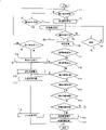
Fig. 6 is the flow chart of the preceding half section operating process of express liquid syringe;
Fig. 7 is the flow chart of expression second half section; With
Fig. 8 is the flow chart of expression MRI instrumentation process.
The specific embodiment
Carry out following explanation in conjunction with the embodiment of the invention according to accompanying drawing.Liquid infusion system 1000 according to embodiment of the present invention comprises fluid injector 100, fluid infusion apparatus 200 and MRI instrument 300, and it is the diagnosing image instrument as Fig. 1 to 4 explanation.This system arrives (not shown) in patient's body with injection of contrast medium and analog as liquid, and detailed description is seen below.
Open the rear end of the ducted body 211 of cylinder part 210, and piston 220 is inserted into the inside of ducted body 211 from opening.Cylinder part 210 has the cylinder flange 213 that is formed at the rear end exterior periphery, and piston element 220 has the piston flange 221 that is formed at the rear end exterior periphery.
In present embodiment liquid infusion system 1000, the used fluid infusion apparatus 200 of at least a portion is pre-to load type, and the fluid infusion apparatus 200 of loading type in advance is with cylinder part 210 shipments of filling up liquid.
The cylinder part 210 of fluid infusion apparatus 200 has printing or label at the 2 d code (2D) 214 of its excircle, wherein 2 d code 214 is represented the various data item of being concerned about about fluid infusion apparatus 200, but load type in advance or load stroke of the ID data of type, the ID data of discerning each injection device part, capacity, cylinder part 210 proof pressures, cylinder part 210 internal diameters, piston or the like again such as title, identification, be embodied in the 2 d code.
In addition,,, whether to be used for the ID data of CT or MR, embody and be encoded to 2 d code 214 as title, composition, viscosity, Expiration Date and demonstration so more about loading the various data item of liquid if fluid infusion apparatus 200 is the pre-type of loading.And liquid is contrast agent in the pre-filling fluid infusion apparatus 200 if be seated in, and more data item so as the types of variables of the injection speed that changes according to the time, embodies and be encoded to the part of 2 d code 214 as needs.
As a reference, fluid infusion apparatus 200 comprises that contrast agent is housed is the contrast medium injection apparatus 200C of liquid and the normal saline injection device 200W that normal saline is a liquid is housed.Contrast agent and/or normal saline injection device 200C and 200W can be installed in the fluid injector simultaneously.
Be contained in contrast agent and/or normal saline injection device 200C, 200W in the fluid injector 100, as mentioned above, be connected to the patient by injection device ancillary equipment such as bifurcated catheter 230, wherein 2 d code 214 gives numerical value also for the ancillary equipment of these injection devices, and the proof pressure of many data item such as title and ancillary equipment also embodies and is coded in forms 2 d code 214 in the 2 d code.
As shown in Figure 3, the fluid injector 100 of present embodiment 100 has injection control apparatus 101 and is configured to the injection head 110 of self-contained unit, and they connect by communication cables 102 electric wires.
Whether cylinder holding mechanism 116 (wrong? the main operation panel is represented in front 116) be formed at female 114 with irregular form of grooves, each cylinder flange 213 removably engages thus.Liquid infusion mechanism 117 has ultrasonic motor 118 separately, even ultrasonic motor does not produce magnetic field in the running yet, it makes piston element 220 move slidably by similar means (not shown)s such as screw mechanisms as power source.In addition, liquid infusion mechanism 117 has the built-in load cell 119 that detection is applied to piston element 220 upward pressures separately.
Because two females 114 of injection head 110 are suitable for holding contrast agent and/or normal saline injection device 200C, 200W respectively, these two females 114 and two liquid infusion mechanisms 117 form the 117C of contrast-medium injection mechanism that is used for injection of contrast medium and are used for the normal saline injection mechanism 117W of injecting normal saline in patient's body.
In addition, in the fluid injector 100 of present embodiment, each element of injection head 110 is made by namagnetic substance at least, can not will carry out magnetic shield with the part that namagnetic substance is made.
For example, ultrasonic motor 118, load cell 119 etc. is made by nonmagnetic metal such as phosphor bronze alloy (Cu+Sn+P), titanium alloy (Ti-6Al-4V) and magnesium alloy (Mg+Al+Zn), and a body 113 and analog are made by non-magnetic resin.
In the fluid injector 100 of present embodiment, above-mentioned various devices are connected on the computer installation 130 as shown in Figure 2, by it various devices are carried out complicated control.Computer installation 130 is for having a CPU (central processing unit), ROM (read only memory) 132, RAM (easy assess memorizer) 133, a single chip microcomputer that I/F (interface) 134 hardware such as grade are formed by so-called.
Because computer installation 130 is according to the computer program operation of above-mentioned installation, the fluid injector 100 of present embodiment has various logic functions as shown in Figure 1, as decoding function 141, operation control function 142 etc., corresponding to various device.
More specifically, used fluid infusion apparatus 200, the authentication data that prolongs pipe etc. are stored among the RAM133 as the affirmation condition.2 d code 214 when optically read liquid input device of ccd video camera and prolongation pipe 230, and the code that reads is by CPU 131 decodings, and the authentication data of the decoding of liquid input device 200, prolongation pipe 230 etc. and the authentication data that is stored among the RAM 233 compare.
If the authentication data of decoding is not stored, tutorial message is such as " this product is not registered as a spendable equipment; Whether PLSCONFM can be used " be presented on the master/secondary touch panel 104,121 and confirm warning as one, also by acoustical signal of speaker unit 105 outputs.
In addition, the current data of the daily renewal of RAM 133 storages and time are as an affirmation condition, when the effect duration data that are provided with for safe handling decode from the 2 d code 214 of fluid infusion apparatus 200, effect duration data and current data and time compare.If the current time has exceeded the effect duration scope of data, know that information was presented on the master/secondary touch panel 104,121 as an affirmation warning as " this product has exceeded the effect duration scope; please use new product ", also acoustical signal of output from speaker unit 105.
In addition, because load fluid infusion apparatus 200 in advance an identification symbol for each product foundation is arranged, and be coded in the 2 d code, form 2 d code 214, the pre-product code of loading fluid infusion apparatus 200 of data storage function 148 storages, this loads the implementation that fluid infusion apparatus 200 is installed on the injection head 110 and experiences injection operation in advance.
In this case, data comparing function 146 is compared the identification symbol of being stored with the identification symbol that decodes from 2 d code 214, if the identification symbol that is compared is consistent, alarm function 147 operation so, tutorial message as " this product uses in the past; Please use a new product " confirm that as one warning is presented on the master/secondary touch panel 104,121, and by acoustical signal of speaker unit 105 outputs.
The decoded result of 2 d code 214 is stored in memory function 151 operations as a result, presentation control function 152 operations, leading/showing on the secondary touch panel 104,121 decoded result of storage, 153 operations of injection control function, the operation that comes controlling liquid injection mechanism 117 according to the decoded result of being stored.
More particularly, in the 2 d code 214 of fluid infusion apparatus 200, establish about the required various data item of fluid infusion apparatus 200, as title, proof pressure and volume, with the various data item that are filled in liquid in the fluid infusion apparatus such as title, composition and effect duration for using safely, these different data temporarily are stored among the RAM 133, supply then and are presented on the master/secondary touch panel 104,121.
In addition, if the control data of liquid infusion mechanism 117 is based upon in the 2 d code 214 of fluid infusion apparatus 200, control data is stored among the RAM 133, and the operation that CPU 131 comes controlling liquid injection mechanism 117 according to the control data of storing.For example, if the 2 d code 214 of injection device 200 comprises a types of variables that changes foundation according to contrast-medium injection speed in time relatively, CPU 131 passes the speed of operation that changes the liquid infusion mechanism 117 that is used for contrast agent in time according to types of variables.
And, if the 2 d code of fluid infusion apparatus 200 and prolongation pipe 230 data that are endowed about they proof pressures, the operation of CPU 131 controlling liquid injection mechanisms 117 is no more than the proof pressure that is stored among the RAM133, and this proof pressure detects by load cell 119 and gets.
If the 2 d code 214 of fluid infusion apparatus 200 is endowed the data about capacity, CPU 131 is according to the operation that is stored in volume control liquid infusion mechanism 117 among the RAM 133.In addition, the 2 d code 214 as relative injection device 200C and normal saline injection device 200W is read CPU 131 operation in tandem contrast-medium injection 117C of mechanism and normal saline injection mechanism 117W respectively.
Though the various functions of fluid injector 100 can realize by the needed hardware device of environment for use such as master/secondary touch panel 104,121, resource that necessary part can be by being stored in information recording medium such as ROM 132 etc. and the functional hardware of CPU 131 are realized according to computer program.
This computer program is stored among information recording medium such as the RAM 133 etc., as the software that excites CPU 131 grades, carries out the following step: to decoding by ccd video camera 122 optically read 2 d codes 214; Relatively be stored in the affirmation condition in RAM 133 grades and the decoded result of 2 d code 214; Warn according to comparative result announcement affirmation by a display device such as master/secondary touch panel 104,121; The identification symbol of the fluid infusion apparatus of injection operation implementation is installed and is experienced in storage; The identification symbol of storage and the identification symbol that decodes from 2 d code 214 are compared; Confirm warning according to comparative result by display device etc. and similar devices such as master/secondary touch panel 104,121 announcements; The decoded result of storage 2 d code 214 is medium to RAM 133; Leading/showing on the secondary touch panel 104,121 decoded result of storage; And the decoded result operation that comes the controlling liquid injection mechanism according to storage.
[operation of embodiment]
When using the fluid injector 100 of the above-mentioned structure of present embodiment, operator's (not shown) is arranged in fluid injector 100 near the imaging device 301 of MRI instrument as shown in Figure 4, and is ready to contrast agent and/or normal saline injection device 200C, 200W and prolongs pipe 230.
Next, contrast agent and/or normal saline injection device 200C, 200W and the 2 d code 214 that prolongs pipe 230 are arranged on the relative position of ccd video camera 122 of fluid injector 100 injection heads 110, as shown in Figure 6 (step S1) these ccd video camera 122 optically read 2 d codes 214.
Then, optically read 2 d code 214 is by computer installation 130 (step S2) decoding, and decoded data is compared with the affirmation condition in being stored in RAM 133 (step S3).The authentication data of available fluid infusion apparatus 200, prolongation pipe 230 etc. stores as the affirmation condition in present case.Therefore, if the authentication data of fluid infusion apparatus 200 grades of decoding does not store as the affirmation condition from 2 d code 214, tutorial message is as " this product is not registered as available devices; Whether PLSCONFM is available " confirm that as one warning is presented on the master/secondary touch panel 104,121, also by acoustical signal of speaker unit 105 (step S4) output.
Under this situation, because tutorial message as " you wish this product is registered as an enabled production? be/not (Y/N) " be also shown on the master/secondary touch panel 104,121, and further by acoustical signal of speaker unit 105 outputs, leading/carry out input operation on the secondary touch panel 104,121 (step S5), incoming symbol " Y ", registration is as the authentication data of affirmation condition (step S6) in RAM 133.
Perhaps, if an incoming symbol " N " is input on the master/secondary touch panel 104,121 (step S5), fluid injector 100 has recovered its initial conditions.As a result, the operator prepares a new suitable product, and begins operation (step S1 to S3) once more.
In addition, if the effect duration data of the safe handling of coming out from 2 d code 214 decoding of fluid infusion apparatus 200 have exceeded existing time and date (step S3) scope, tutorial message is as " this product has exceeded effect duration; Please use new product " then be presented on the master/secondary touch panel 104,121, and confirm that as one warning is by speaker unit 105 output sound signals, because current date and time also stores as the affirmation condition.
It should be noted that, because no longer carrying out above storing new this operation of affirmation condition once more under the situation of effect duration, and fluid injector 100 is automatically stored its initial condition (step S5) again, so the operator will prepare the new fluid infusion apparatus that does not exceed effect duration 200, and restart this process (step S1 to S3).
To after confirming having checked of term harmonization, can determine from the decoded result of 2 d code 214 whether the product of being concerned about is the fluid infusion apparatus 200 of loading type (step S7) in advance when above-mentioned.If fluid infusion apparatus 200 is the pre-type of loading, compare from 2 d code 214 identification symbol that decodes and the identification symbol that is stored in the RAM 133 (step S8) so.
If the identification symbol that is compared meets mutually, a tutorial message is as " this product used in the past so; Please use new product " announcement leading/secondary touch panel 104,121 on, and confirm that as one warning is by speaker output sound signal (step S9).
Also in this case, fluid injector 100 is stored its initial conditions again, and the operator prepares a new former original pre-filling fluid infusion apparatus 200 subsequently, and restarts this process (step S1 to S3).
As fruit product is the pre-fluid infusion apparatus 200 (step S7) of loading type, if perhaps load the not storage (step S8) of identification symbol of fluid infusion apparatus 200 in advance, the decoded result of 2 d code 214 is stored among the RAM 133 and is presented on the master/secondary touch panel 104,121 (step S10).
More particularly, because the 2 d code of fluid infusion apparatus 214 is endowed various data item such as title, proof pressure and the capacity of fluid infusion apparatus 200, also comprise the various projects such as effect duration as title, composition, safe handling that the liquid that is filled in the fluid infusion apparatus is concerned about, these various data item that temporarily are stored among the RAM 133 are presented on the master/secondary touch panel 104,121.
As reference, because 2 d code 214 assignment need to show and do not need the data presented item in various, for example, a binary labelling is given to each different pieces of information item and is shown whether these data item of being concerned about need to show.Fluid injector 100 shows the project of right quantity according to the decoded result of 2 d code 214.
Next, the control data that is used for controlling liquid injection mechanism 117 extracts from 2 d code 214, and these data are written in (step S11) among the RAM 133.As reference,, the control data of acquiescence is written among the RAM 133 if the control data of setting up can not be included in the decoded result of 2 d code 214.
When the operator is placed on the 2 d code 214 of contrast agent and/or normal saline injection device 200C, 200W and prolongation pipe 230 relative position of the ccd video camera on the injection head 110 122 in the fluid injector 100, the affirmation warning of 2 d code and decoded result are presented on the secondary touch panel 121 of injection head 110, and the control data that is used for controlling liquid injection mechanism 117 is also set up.
Next, the operator with contrast agent and/or normal saline injection device 200C, 200W be positioned at Image-forming instrument 301 before patient's (not shown) be connected, and the cylinder part 210 of fluid infusion apparatus 200 is placed in the injection head 110.
An operational order is handled master/secondary touch panel 104,121 and main operation panel 103 brings into operation when the operator imports, and fluid injector 100 detects input operation instruction (step S12) and sends the signal (step 15) that shows that MRI instrument 300 comes into operation.
With reference to figure 8, as mentioned above,, MRI instrument 300 moves the signal (step T2) that begins when receiving demonstration from fluid injector 100, and MRI instrument 300 returns notifies the signal that brings into operation to give liquid syringe 100, and the execution diagnosing image is operated (step T8).In order to reach this target, in the present embodiment diagnostic imaging system 1000, the liquid infusion process that the imaging operation of MRI instrument 300 is followed fluid injector 100 all the time.
As reference, at present embodiment diagnostic imaging system 1000, when fluid injector 100 is in SBR recited above (step S12 to S14), and handle MRI instrument 300 beginning imaging operations (step T1) as Fig. 6 and input shown in Figure 8 instruction, the injection process of fluid injector 100 is accompanied by (the step T4 all the time of the diagnosing image process of MRI instrument 300, from step T6 forward, S13, from step S18 forward).
In fluid injector 100, when carrying out the sequence of operations injecting fluid (forward) from step S19, the used time calculates from injection (step S19), corresponding to the time of above-mentioned cost, the operating sequence ground of 117C of contrast-medium injection mechanism and normal saline injection mechanism 117W is controlled in real time, and control data is from 2 d code 214 decodings as shown in Figure 7.
In order to achieve this end, if be based upon types of variables in the 2 d code 214 of contrast medium injection apparatus 200C according to the injection speed that changes contrast agent time lapse, according to types of variables, the speed of operation of the 117C of contrast-medium injection mechanism is along with the time changes.
In addition, when liquid infusion mechanism 117 as above-mentioned being driven, computer installation 130 obtains load cell 142 real-time detected pressure (step S20).
Then, the viscosity of the liquid that comes out according to from 2 d code 214, decoding and the internal diameter (step S21) of cylinder part 210, the injection pressure of liquid is calculated from load cell 142 detected pressure, the operation of liquid infusion mechanism 117 is controlled in real time, makes injection pressure can not surpass the pressure limit (step S23) that decodes from 2 d code 214.
In addition, in in the present embodiment the fluid injector 100 and MRI instrument, if above-mentioned SBR (step S14, T3) detect the generation of abnormal conditions in, if perhaps in an operating process, detect abnormal conditions generation (step S23, T9), then abnormal conditions are announced (step S26, T16), and the execution of interrupt operation (step S28, T18).
Because another instrument (step S25, T15) generation of abnormal conditions also obtains announcement, other instruments of receiving that announcement takes place abnormal conditions also provide the announcement that abnormal conditions take place (step T16, S26).In addition because the interruption of an instrumentation also to another instrument announce (step S27, T17), other receive interrupt operation announcement (step T13, instrument S31) also interrupt executory operation (step T18, S28).
In addition, when an instrument is carried out input operation, make its control interrupt an operation (step S29, T18), also to another instrument announce (step S27, T17).As a result, other receive announcement instrument (step T13, S31) carry out interrupt operation (step T18, S28).
In addition, when finishing of in an instrument, operating be detected (step S32, T14), finishing of operation in related instrument, obtain carrying out (step S33, T19), and also announcement give another instrument (step S34, T20).As a result, finishing at other of operation receives that (step T12 also obtains in instrument S31) carrying out in announcement.
[realization of embodiment]
In the liquid infusion system of present embodiment 1000, sequence of operations as: record do the 2 d code 214 of fluid infusion apparatus 200 various data item, optically read 2 d code 214, to they decoding and carry out the scheduled operation of fluid injector 100, make the input mass data to fluid injector 100 and carry out various operations and become possibility.
Especially, because 2 d code 214 has very big code capacity with respect to bar code, it is possible in advance the various data item in the fluid injector 100 and their authentication code being stored, do not need to obtain the storage data that go out authentication code from bar code decoding again, even a large amount of completed new data also can easily be input in the fluid injector 100.
In addition, in present embodiment liquid infusion system 1000, the operator is easy and confirm that reliably various data item about used fluid infusion apparatus 200 grades are possible.Because the part of 2 d code 214 decoded results is stored and is presented in the master/secondary touch panel 104,121 at least.
Especially, in the time of on 2 d code 214 that the operator will be installed in the fluid infusion apparatus 200 on the injection head 110 is placed in respect to the position of ccd video camera 122, ccd video camera 122 and secondary touch panel 121 are fixed on this arrangement on the injection head 110 with the fluid infusion apparatus 200 that is installed in the there, permission shows multiple decoded data item on the secondary touch panel 121 of adjacency ccd video camera 122, like this can be easy confirm intuitively the several data item of the fluid infusion apparatus that uses 200 grades.
And, can receive an input operation for well because show the secondary touch panel 121 of 2 d code 214 decoded results, when fluid injector 100 was carried out various operation according to 2 d code 214 decoded results, the operator can adjust the various operations of fluid injector 100 as it with being willing to easily like this.
In addition, present embodiment fluid injector 100 can be compared the affirmation condition of storage and the decoded result of 2 d code 214, and warning is confirmed in announcement when need opportunity.According to this method, for example, if there is the people to want to use the obsolete fluid infusion apparatus 200 of being concerned about fluid injector 100, the injection device 200 that perhaps uses liquid to exceed to use effect duration safely, confirm to warn and announce, so just can prevent various medical science accidents satisfactorily.
Especially, in present embodiment fluid injector 100, the 2 d code 214 of loading type injection device 200 when desire is read, the identification symbol of each injection part is stored, confirm to warn and announce, eliminate such medical science accident thus: a pre-fluid infusion apparatus 200 of loading type is repeated to use, and this fluid infusion apparatus once was used, and should be thrown away.
In addition, this makes and can on purpose use pre-filling or load fluid infusion apparatus 200, because the fluid injector in the present embodiment 100 can detect the fluid infusion apparatus of whether being concerned about 200 according to the decoded result of 2 d code 214 and still load type again for the pre-type of loading, and aforesaid operations is only carried out pre-the filling under the type cases.
In addition, in present embodiment liquid infusion system 100, not only give fluid infusion apparatus 200 but also give injection device ancillary equipment and go on record as the 2 d code 214 that prolongs pipe 230 etc.Therefore, make fluid injector 100 to control to be adapted to the injection operation that prolongs pipe 230 proof pressures such as grade, thus can suitably eliminate the medical science fault such as: can not be used for the prolongation pipe 230 of care fluid injector 100 be used.
Moreover, in present embodiment liquid infusion system 1000, because the liquid infusion that fluid injector 100 is carried out and the photographic images of MRI instrument 300 are automatically interconnection, can shoot suitable sequential diagnostic image to the patient, this patient obtains the treatment of successive contrast agent and normal saline in good time.
The present invention is not limited to the foregoing description, and allows in a scope bigger variation to be arranged not departing under the main idea situation of the present invention.For example, be example with the foregoing description, the arrangement that is used for the ccd video camera 122 of optically read 2 d code 214 causes satisfied operating characteristics, shows that the secondary touch panel 121 of decoded result is placed on the injection head 110 at fluid infusion apparatus 200 configuration places.
In any case, also ccd video camera and secondary touch panel 121 might be configured in the isolated position of injection head 110 on, also further ccd video camera 122 might be connected with fluid injector 100 by electric wire or wireless connection device (not shown) as a portable independent device.
In addition, because digital camera can optically read 2 d code, and be used widely with the portable phone of digital camera one, also this device might be connected to fluid injector 100 as an instrument that reads code by electric wire or wireless connection device (not shown).
In addition, because the foregoing description illustrates a kind of layout, ccd video camera 122 is positioned at a side of injection head 110 in this layout, ccd video camera 122 is configured on the position of the optically read 2 d code 214 that is installed in the fluid infusion apparatus 200 on the fluid injector of energy.In this case, when fluid infusion apparatus 200 was installed on the injection head 110, because 2 d code 214 can be read by automated optical by ccd video camera 122, it is just unnecessary that the operator gives 2 d code 214 for ccd video camera 122.
In addition, the fluid injector with said structure can be configured and make and allow liquid infusion mechanism 117 only to operate when ccd video camera 122 optical detection 2 d codes 214.In this case, because liquid infusion mechanism 117 only just operates when injection device 200 can be placed on the injection head 110 rightly, so, for example, when fluid infusion apparatus 200 and injection head 110 were separated, the 117 automatic shut-down operations of liquid infusion mechanism were feasible.
In addition, with the foregoing description is example, though external peripheral surface record 2 d code 214 at fluid infusion apparatus 200 cylinder parts 210,2 d code 214 is recorded in the outer surface or the rear end surface of fluid infusion apparatus 200, maybe can select to be recorded on the packaging material, also be feasible (not shown).
In addition, with the foregoing description is example, though record 2 d code 214 on fluid infusion apparatus 200 and prolongation pipe 230, record 2 d code 214 also is feasible like this, as: only on fluid infusion apparatus 200 or selectively be recorded on each different injection device ancillary equipment except that prolonging pipe 230, as catheter or liquid bottles (not shown).
In addition, with the foregoing description is example, though record 2 d code 214 on fluid infusion apparatus 200 and prolongation pipe 230, to be recorded in the patient also be feasible on one's body with giving 2 d code 214 to patient's various data item, for example: be looped around the wrist strap of patient's wrist, list the (not shown)s such as medical science card of the every data item of patient.
In this case, because variously can easily be input in the fluid injector 100, be feasible according to patient's body weight and age control injection operation, thereby can avoid automatically and the incoherent liquid infusion of patient disease about the patient's data item.
In addition, with the foregoing description is example, though the form with 2 d code 214 such as the various data item of fluid infusion apparatus 200 grades is input in the fluid injector 100, but this also is feasible, for example, the data in the source of the data of updating computer program and fluid injector 100, this fluid injector 100 uses such input data item 2 d code 214.
In addition, with the foregoing description is example, though the injection of contrast agent and normal saline is all via the fluid injector 100 that is equipped with relative and/or salt injection mechanism 117C and W, by using single liquid infusion mechanism 117, add the only fluid injector of injection of contrast medium, perhaps, add the fluid injector that is used to inject above two kinds of liquid by using above two liquid infusion mechanisms 117 (both does not show), these all are feasible.
Further, with the foregoing description is example, though use the MRI instrument as the diagnosing image instrument, and use fluid injector 100 to be the MR injection of contrast medium, this is feasible, for example: use CT scanner or PET instrument as the diagnosing image instrument, and be adapted to the contrast agent of institute's use instrument by the fluid injector injection.
Further, framework with the foregoing description is an example, though by the operation of CPU 131 according to the computer program that is stored in RAM 133 grades, the function of various fluid injectors 100 can logically be realized, in any case, realize that as special functional hardware so various functions are possible, the software of a part of this function of storage and adding also are possible as other functions of hardware in RAM 133.
In addition, though suppose manufacturer's record 2 d code 214 on fluid infusion apparatus 200 and prolongation pipe 230 in the above-described embodiments, feasible also has, for example: 2 d code 214 is printed onto on the label in hospitals and other places, there, fluid infusion apparatus 200 obtains using, and these labels are sticked on fluid infusion apparatus 200 grades, and coming provides 2 d code to liquid injection device 200 grades.
In this case, be fine like this, for example:, be feasible because desired data are provided for the place to use of liquid injection device 200 loading again on the fluid infusion apparatus 200 with the various data item of 2 d code 214 forms record about liquid.Further, be printed and use 2 d code 214 data in those places can, for example, give those places by manufacturer-supplied as the additional data of an Email, perhaps can on the homepage of manufacturer, provide as predetermined data download.
In addition, with the foregoing description is example, be installed in fluid injector 100 though be used for the video camera 122 of the 2 d code 214CCD of optically read fluid infusion apparatus 200, so also be feasible, for example:, ccd video camera is fixed on temperature of liquid keeps on the instrument for keeping fluid infusion apparatus 200 (not shown) on proper temperature.
In this case, it is possible on suitable temperature that temperature of liquid keeps instrument to keep liquid according to the decoded result of 2 d code 214 by control insulation operation, and it also is possible that the decoded result that temperature of liquid keeps instrument to transmit reading result and 2 d code 214 is not fixed in the fluid injector on it to ccd video camera 122.
Claims (15)
1. liquid infusion system, comprise at least one device for injecting liquid, this device for injecting liquid has one and is inserted into a piston element in the cylinder part of filling a kind of liquid slidably, with a fluid injector, this fluid injector by a liquid infusion mechanism, the described cylinder part and the described piston element of the device for injecting liquid of installing are relatively moved mutually, described liquid infusion is arrived in patient's body, wherein
Described device for injecting liquid have the several data item that is recorded in the 2 d code and
Described fluid injector comprises:
One can optically read 2 d code code reading device,
Code decoding device that optically read 2 d code is decoded and
Carry out the operating control device of predetermined operation according to described 2 d code decoded result for one, wherein
Described 2 d code comprises a types of variables according to time change liquid infusion speed, and
Described operating control device changes the speed of operation of described liquid infusion mechanism in time according to described types of variables.
2. liquid infusion system according to claim 1, wherein said fluid injector have one for the data presentation device that shows various data item and
Described operating control device has a storage device as a result and the display control unit for the decoded result of demonstration at least a portion storage in described data presentation device for the described 2 d code decoded result of storage.
3. liquid infusion system according to claim 2, wherein said fluid injector comprise the injection control unit that a described at least operating control device is installed on it; Separate the injection head that forms with one with described injection control unit, described liquid infusion mechanism and described data presentation device wherein are installed at least.
4. liquid infusion system according to claim 3, wherein said code reading device also is installed on the described injection head.
5. liquid infusion system according to claim 1, wherein said fluid injector has described code reading device, and this code reading device is placed in the 2 d code of described mounted device for injecting liquid by on the optically read position.
6. liquid infusion system according to claim 5, wherein said operating control device can be only when the described 2 d codes of described code reading device optical detection the time, make the operation of described liquid infusion mechanism.
7. according to any one described liquid infusion system in the claim 1 to 6, wherein said operating control device has a storage device as a result and the injection control apparatus that the decoded result according at least a portion storage is the operation of the described liquid infusion of control mechanism for the decoded result of the described 2 d code of storage.
8. liquid infusion system according to claim 7, be equipped with a pre-filling device for injecting liquid that encapsulates with the contrast agent as liquid filling, this contrast-medium injection is in patient's body when patient's diagnostic image is taken by a diagnosing image instrument.
9. according to any one described liquid infusion system in the claim 1 to 6, wherein said operating control device is equipped with one to be used to store the affirmation storage device that condition is confirmed in pre-filling, the data comparison means of an affirmation condition that is used for relatively storing and described 2 d code decoded result and a means for signalling that is used to announce an affirmation warning according to comparative result.
10. according to any one described liquid infusion system in the claim 1 to 6, be equipped with one be filled the pre-filling fluid infusion apparatus that liquid is packaged together, described pre-filling fluid infusion apparatus has at least one identification symbol that is used for being based upon described 2 d code, wherein
Described operating control device is equipped with the data storage device of the described identification symbol that is used for the storage of liquids injection device, fluid infusion apparatus is configured and starts to carry out an injection operation, one is used for more stored described production code member and described data comparison means and alarm device that is used to announce an affirmation warning when the identification symbol that is compared meets mutually that newly reads identification symbol.
11. according to any one described liquid infusion system in the claim 1 to 6, also be equipped with and comprise an injection device ancillary equipment that is adapted to the hollow spicule parts that are inserted into the patient and carry described liquid, one is used to connect described spicule and described fluid infusion apparatus to carry the prolongation pipe of described liquid, with an one-way cock that is used to control the described prolongation pipe of being inserted into of described liquid flow direction, wherein
Expression also is recorded in the described injection device ancillary equipment with the 2 d code that each described injection device ancillary equipment item is set up the various data item that connect.
12., also be equipped with to comprise that patient's ancillary equipment that is used to be worn over the wrist strap on described patient's wrist and one are used to import various about patient's data item form card, wherein according to any one described liquid infusion system in the claim 1 to 6
Expression also is recorded on described patient's ancillary equipment with the 2 d code that each described patient's ancillary equipment connects.
13. according to any one described liquid infusion system in the claim 1 to 6, also be equipped with a temperature of liquid that keeps the liquid in the fluid infusion apparatus under pre-definite temperature, to use with the heat maintaining body to keep instrument, isolated with described fluid injector, wherein said temperature of liquid keeps instrument also to be equipped with
A kind of code reading device that is used for optically read described 2 d code,
A kind of be used to decode by the code decoding device of optically read described 2 d code and
A kind of operating control device that is used to carry out scheduled operation according to described 2 d code decoded result.
14. a fluid injector is equipped with
A kind of code reading device that is used for optically read 2 d code,
A kind of be used to decode by the code decoding device of optically read described 2 d code and
A kind ofly be used to carry out the operating control device of scheduled operation, wherein according to described 2 d code decoded result
Described fluid injector is adapted to according to any one liquid infusion system in the claim 1 to 12.
15. a temperature of liquid keeps instrument, is equipped with
A kind of code reading device that is used for optically read 2 d code,
A kind of be used to decode by the code decoding device of optically read described 2 d code and
A kind of operating control device that is used for carrying out scheduled operation according to described 2 d code decoded result, wherein
Keep instrument to be adapted to liquid infusion system according to the described temperature of liquid of claim 13.
Applications Claiming Priority (2)
| Application Number | Priority Date | Filing Date | Title |
|---|---|---|---|
| JP2003368858 | 2003-10-29 | ||
| JP2003368858A JP2005131007A (en) | 2003-10-29 | 2003-10-29 | Medical fluid injection system |
Publications (2)
| Publication Number | Publication Date |
|---|---|
| CN1618475A CN1618475A (en) | 2005-05-25 |
| CN100409908C true CN100409908C (en) | 2008-08-13 |
Family
ID=34646398
Family Applications (1)
| Application Number | Title | Priority Date | Filing Date |
|---|---|---|---|
| CNB200410086793XA Expired - Fee Related CN100409908C (en) | 2003-10-29 | 2004-10-29 | Liquid injection system |
Country Status (4)
| Country | Link |
|---|---|
| US (1) | US20050148869A1 (en) |
| EP (1) | EP1563859A1 (en) |
| JP (1) | JP2005131007A (en) |
| CN (1) | CN100409908C (en) |
Families Citing this family (71)
| Publication number | Priority date | Publication date | Assignee | Title |
|---|---|---|---|---|
| US8177762B2 (en) | 1998-12-07 | 2012-05-15 | C. R. Bard, Inc. | Septum including at least one identifiable feature, access ports including same, and related methods |
| US8489176B1 (en) | 2000-08-21 | 2013-07-16 | Spectrum Dynamics Llc | Radioactive emission detector equipped with a position tracking system and utilization thereof with medical systems and in medical procedures |
| US8565860B2 (en) | 2000-08-21 | 2013-10-22 | Biosensors International Group, Ltd. | Radioactive emission detector equipped with a position tracking system |
| US8909325B2 (en) | 2000-08-21 | 2014-12-09 | Biosensors International Group, Ltd. | Radioactive emission detector equipped with a position tracking system and utilization thereof with medical systems and in medical procedures |
| JP4127202B2 (en) * | 2003-12-12 | 2008-07-30 | 株式会社デンソー | Automatic headlamp optical axis adjustment device for vehicles |
| US8586932B2 (en) | 2004-11-09 | 2013-11-19 | Spectrum Dynamics Llc | System and method for radioactive emission measurement |
| US8571881B2 (en) | 2004-11-09 | 2013-10-29 | Spectrum Dynamics, Llc | Radiopharmaceutical dispensing, administration, and imaging |
| US9040016B2 (en) | 2004-01-13 | 2015-05-26 | Biosensors International Group, Ltd. | Diagnostic kit and methods for radioimaging myocardial perfusion |
| US9470801B2 (en) | 2004-01-13 | 2016-10-18 | Spectrum Dynamics Llc | Gating with anatomically varying durations |
| WO2006051531A2 (en) | 2004-11-09 | 2006-05-18 | Spectrum Dynamics Llc | Radioimaging |
| US7968851B2 (en) | 2004-01-13 | 2011-06-28 | Spectrum Dynamics Llc | Dynamic spect camera |
| US7176466B2 (en) | 2004-01-13 | 2007-02-13 | Spectrum Dynamics Llc | Multi-dimensional image reconstruction |
| EP1778957A4 (en) | 2004-06-01 | 2015-12-23 | Biosensors Int Group Ltd | Radioactive-emission-measurement optimization to specific body structures |
| US7507221B2 (en) | 2004-10-13 | 2009-03-24 | Mallinckrodt Inc. | Powerhead of a power injection system |
| US9316743B2 (en) | 2004-11-09 | 2016-04-19 | Biosensors International Group, Ltd. | System and method for radioactive emission measurement |
| US8423125B2 (en) | 2004-11-09 | 2013-04-16 | Spectrum Dynamics Llc | Radioimaging |
| US9943274B2 (en) | 2004-11-09 | 2018-04-17 | Spectrum Dynamics Medical Limited | Radioimaging using low dose isotope |
| US8615405B2 (en) | 2004-11-09 | 2013-12-24 | Biosensors International Group, Ltd. | Imaging system customization using data from radiopharmaceutical-associated data carrier |
| WO2008059489A2 (en) | 2006-11-13 | 2008-05-22 | Spectrum Dynamics Llc | Radioimaging applications of and novel formulations of teboroxime |
| US8029482B2 (en) | 2005-03-04 | 2011-10-04 | C. R. Bard, Inc. | Systems and methods for radiographically identifying an access port |
| US9474888B2 (en) | 2005-03-04 | 2016-10-25 | C. R. Bard, Inc. | Implantable access port including a sandwiched radiopaque insert |
| US7947022B2 (en) | 2005-03-04 | 2011-05-24 | C. R. Bard, Inc. | Access port identification systems and methods |
| EP1858565B1 (en) | 2005-03-04 | 2021-08-11 | C.R. Bard, Inc. | Access port identification systems and methods |
| EP3884989B1 (en) | 2005-04-27 | 2022-07-13 | C. R. Bard, Inc. | Vascular access port |
| US8147455B2 (en) | 2005-04-27 | 2012-04-03 | C. R. Bard, Inc. | Infusion apparatuses and methods of use |
| US10307581B2 (en) | 2005-04-27 | 2019-06-04 | C. R. Bard, Inc. | Reinforced septum for an implantable medical device |
| US8837793B2 (en) | 2005-07-19 | 2014-09-16 | Biosensors International Group, Ltd. | Reconstruction stabilizer and active vision |
| US8644910B2 (en) | 2005-07-19 | 2014-02-04 | Biosensors International Group, Ltd. | Imaging protocols |
| WO2007032343A1 (en) * | 2005-09-12 | 2007-03-22 | Nemoto Kyorindo Co., Ltd. | Medicinal liquid injection device |
| WO2007105725A1 (en) * | 2006-03-14 | 2007-09-20 | Nemoto Kyorindo Co., Ltd. | Medical image system |
| US8894974B2 (en) | 2006-05-11 | 2014-11-25 | Spectrum Dynamics Llc | Radiopharmaceuticals for diagnosis and therapy |
| DE102006047537A1 (en) | 2006-10-07 | 2008-04-10 | Sanofi-Aventis Deutschland Gmbh | Optically determining the stopper position in glass ampoules |
| US9265912B2 (en) | 2006-11-08 | 2016-02-23 | C. R. Bard, Inc. | Indicia informative of characteristics of insertable medical devices |
| US9642986B2 (en) | 2006-11-08 | 2017-05-09 | C. R. Bard, Inc. | Resource information key for an insertable medical device |
| WO2008075362A2 (en) | 2006-12-20 | 2008-06-26 | Spectrum Dynamics Llc | A method, a system, and an apparatus for using and processing multidimensional data |
| WO2009011103A1 (en) * | 2007-07-17 | 2009-01-22 | Nemoto Kyorindo Co., Ltd. | Medical fluid infusing device, fluoroscopic image pickup apparatus, and computer program |
| US8062008B2 (en) | 2007-09-27 | 2011-11-22 | Curlin Medical Inc. | Peristaltic pump and removable cassette therefor |
| US8083503B2 (en) | 2007-09-27 | 2011-12-27 | Curlin Medical Inc. | Peristaltic pump assembly and regulator therefor |
| US7934912B2 (en) | 2007-09-27 | 2011-05-03 | Curlin Medical Inc | Peristaltic pump assembly with cassette and mounting pin arrangement |
| US8521253B2 (en) | 2007-10-29 | 2013-08-27 | Spectrum Dynamics Llc | Prostate imaging |
| US9579496B2 (en) | 2007-11-07 | 2017-02-28 | C. R. Bard, Inc. | Radiopaque and septum-based indicators for a multi-lumen implantable port |
| US8052645B2 (en) | 2008-07-23 | 2011-11-08 | Avant Medical Corp. | System and method for an injection using a syringe needle |
| CA2724641C (en) | 2008-05-20 | 2020-03-24 | Avant Medical Corp. | Autoinjector system |
| US20110137162A1 (en) * | 2008-08-19 | 2011-06-09 | Bruce John K | Power Injector with Syringe Communication Logic |
| CN102271737B (en) | 2008-10-31 | 2016-02-17 | C·R·巴德股份有限公司 | For providing the subcutaneous entry port entered of patient |
| US8932271B2 (en) | 2008-11-13 | 2015-01-13 | C. R. Bard, Inc. | Implantable medical devices including septum-based indicators |
| US11890443B2 (en) | 2008-11-13 | 2024-02-06 | C. R. Bard, Inc. | Implantable medical devices including septum-based indicators |
| DE102009006680A1 (en) * | 2009-01-29 | 2010-08-05 | Medtron Ag | Apparatus and method for injecting a liquid |
| EP2735376B1 (en) | 2009-07-24 | 2017-08-23 | Bayer Healthcare LLC | Syringe for a fluid injector system |
| US8338788B2 (en) | 2009-07-29 | 2012-12-25 | Spectrum Dynamics Llc | Method and system of optimized volumetric imaging |
| EP2281598B1 (en) * | 2009-08-05 | 2019-05-22 | Drägerwerk AG & Co. KGaA | Anaesthetic system |
| ES2695907T3 (en) | 2009-11-17 | 2019-01-11 | Bard Inc C R | Overmolded access port that includes anchoring and identification features |
| CN102933241A (en) * | 2010-04-06 | 2013-02-13 | 株式会社根本杏林堂 | Drug solution injection device |
| LT2699293T (en) | 2011-04-20 | 2019-04-25 | Amgen Inc. | Autoinjector apparatus |
| FR2976565B1 (en) * | 2011-06-14 | 2014-09-05 | Valois Sas | DEVICE FOR DISPENSING FLUID PRODUCT AND METHOD FOR MANUFACTURING SUCH DEVICE. |
| JP2015516628A (en) * | 2012-03-23 | 2015-06-11 | シー・アール・バード・インコーポレーテッドC R Bard Incorporated | Signs that provide information about the characteristics of insertable medical devices |
| USD898908S1 (en) | 2012-04-20 | 2020-10-13 | Amgen Inc. | Pharmaceutical product cassette for an injection device |
| US10492990B2 (en) | 2013-03-15 | 2019-12-03 | Amgen Inc. | Drug cassette, autoinjector, and autoinjector system |
| WO2015020895A1 (en) * | 2013-08-03 | 2015-02-12 | Merit Medical Systems, Inc. | Inflation devices with remote displays, methods and kits related thereto |
| US10046144B2 (en) | 2013-08-03 | 2018-08-14 | Merit Medical Systems, Inc. | Methods of resetting inflation devices |
| EP3212256A4 (en) | 2014-10-28 | 2018-07-18 | Bayer HealthCare LLC | Self-orienting pressure jacket and pressure jacket-to-injector interface |
| NO2689315T3 (en) | 2014-10-28 | 2018-04-14 | ||
| BR112017008878B1 (en) | 2014-10-28 | 2022-10-11 | Bayer Healthcare Llc | PRESSURE SHIRT |
| US9199033B1 (en) | 2014-10-28 | 2015-12-01 | Bayer Healthcare Llc | Self-orienting syringe and syringe interface |
| CA2977683C (en) | 2015-03-04 | 2023-06-13 | Merit Medical Systems, Inc. | Pull tab assemblies and related methods |
| CN107580512B (en) * | 2015-03-13 | 2021-01-15 | 费森尤斯维尔公司 | Infusion device |
| CN108472433B (en) | 2015-11-13 | 2021-12-14 | 拜耳医药保健有限公司 | Nested syringe assembly |
| GB2572122B (en) * | 2017-02-23 | 2022-05-11 | Smiths Medical Asd Inc | Device with identifier |
| WO2018160426A1 (en) | 2017-02-28 | 2018-09-07 | Bayer Healthcare Llc | Identification tag reader system |
| US11191893B2 (en) | 2018-01-31 | 2021-12-07 | Bayer Healthcare Llc | System and method for syringe engagement with injector |
| WO2019209964A2 (en) | 2018-04-26 | 2019-10-31 | Merit Medical Systems, Inc. | Inflation devices with proximity pairing and methods and systems related thereto |
Citations (4)
| Publication number | Priority date | Publication date | Assignee | Title |
|---|---|---|---|---|
| US5651775A (en) * | 1995-07-12 | 1997-07-29 | Walker; Richard Bradley | Medication delivery and monitoring system and methods |
| US6019745A (en) * | 1993-05-04 | 2000-02-01 | Zeneca Limited | Syringes and syringe pumps |
| US20010034506A1 (en) * | 1998-06-15 | 2001-10-25 | Hirschman Alan D. | Encoding of syringe information |
| US20010049608A1 (en) * | 2000-01-25 | 2001-12-06 | Hochman Mark N. | Injection tracking and management system |
Family Cites Families (21)
| Publication number | Priority date | Publication date | Assignee | Title |
|---|---|---|---|---|
| US4966585A (en) * | 1988-05-31 | 1990-10-30 | Gangemi Ronald J | Infusion apparatus |
| US5322500A (en) * | 1991-05-09 | 1994-06-21 | Cardio Pulmonary Supplies, Inc. | Variable ratio blood-additive solution device and delivery system |
| US5328463A (en) * | 1992-09-18 | 1994-07-12 | Namic U.S.A. Corporation | Contrast media and fluid introduction system |
| SG49695A1 (en) * | 1992-10-15 | 1998-06-15 | Gen Hospital Corp | An infusion pump with an electronically loadable drug library |
| CA2129284C (en) * | 1993-11-24 | 1999-03-09 | Kenneth J. Niehoff | Controlling plunger drives for fluid injection in animals |
| US5573515A (en) * | 1995-04-20 | 1996-11-12 | Invasatec, Inc. | Self purging angiographic injector |
| CA2227973C (en) * | 1995-08-25 | 2007-01-16 | Debiotech S.A. | Continuously operating infusion device and method |
| US6070761A (en) * | 1997-08-22 | 2000-06-06 | Deka Products Limited Partnership | Vial loading method and apparatus for intelligent admixture and delivery of intravenous drugs |
| US6468242B1 (en) * | 1998-03-06 | 2002-10-22 | Baxter International Inc. | Medical apparatus with patient data recording |
| JP4331869B2 (en) * | 1999-06-24 | 2009-09-16 | 株式会社根本杏林堂 | Autologous blood perfusion device for coronary artery bypass surgery under heart beat |
| US6355024B1 (en) * | 1999-07-14 | 2002-03-12 | Mallinckrodt Inc. | Medical fluid delivery system |
| JP4593714B2 (en) * | 2000-02-10 | 2010-12-08 | 株式会社根本杏林堂 | Syringe outer cylinder, syringe holder, syringe piston and piston holder |
| US6699230B2 (en) * | 2000-05-10 | 2004-03-02 | Minnesota Medical Physics, Llc | Apparatus and method for out-of-hospital thrombolytic therapy |
| JP4975208B2 (en) * | 2000-10-03 | 2012-07-11 | 株式会社根本杏林堂 | Automatic injection equipment |
| WO2002064195A2 (en) * | 2001-02-14 | 2002-08-22 | Acist Medical Systems, Inc. | Catheter fluid control system |
| CA2492983C (en) * | 2002-07-24 | 2010-07-20 | Deka Products Limited Partnership | Optical displacement sensor for infusion devices |
| JP4286019B2 (en) * | 2003-02-04 | 2009-06-24 | 株式会社根本杏林堂 | Chemical injection system |
| JP4731795B2 (en) * | 2003-02-18 | 2011-07-27 | 株式会社根本杏林堂 | Chemical injection device |
| JP4490642B2 (en) * | 2003-04-01 | 2010-06-30 | 株式会社根本杏林堂 | Chemical injection device |
| JP2005000203A (en) * | 2003-06-09 | 2005-01-06 | Nemoto Kyorindo:Kk | Liquid medication injection system |
| JP2005074065A (en) * | 2003-09-02 | 2005-03-24 | Nemoto Kyorindo:Kk | Medicinal solution injection apparatus |
-
2003
- 2003-10-29 JP JP2003368858A patent/JP2005131007A/en active Pending
-
2004
- 2004-10-27 EP EP04292554A patent/EP1563859A1/en not_active Withdrawn
- 2004-10-28 US US10/974,935 patent/US20050148869A1/en not_active Abandoned
- 2004-10-29 CN CNB200410086793XA patent/CN100409908C/en not_active Expired - Fee Related
Patent Citations (4)
| Publication number | Priority date | Publication date | Assignee | Title |
|---|---|---|---|---|
| US6019745A (en) * | 1993-05-04 | 2000-02-01 | Zeneca Limited | Syringes and syringe pumps |
| US5651775A (en) * | 1995-07-12 | 1997-07-29 | Walker; Richard Bradley | Medication delivery and monitoring system and methods |
| US20010034506A1 (en) * | 1998-06-15 | 2001-10-25 | Hirschman Alan D. | Encoding of syringe information |
| US20010049608A1 (en) * | 2000-01-25 | 2001-12-06 | Hochman Mark N. | Injection tracking and management system |
Also Published As
| Publication number | Publication date |
|---|---|
| JP2005131007A (en) | 2005-05-26 |
| US20050148869A1 (en) | 2005-07-07 |
| CN1618475A (en) | 2005-05-25 |
| EP1563859A1 (en) | 2005-08-17 |
Similar Documents
| Publication | Publication Date | Title |
|---|---|---|
| CN100409908C (en) | Liquid injection system | |
| US7828776B2 (en) | Chemical liquid injection system | |
| JP5802713B2 (en) | Chemical injection system | |
| JP4925828B2 (en) | Chemical injection system | |
| US8211057B2 (en) | Chemical liquid injection system | |
| JP4769197B2 (en) | Chemical injection system | |
| US8211067B2 (en) | Mechanical system | |
| EP1825876A1 (en) | Chemical liquid infusion system | |
| CN105307705A (en) | Chemical injection device and chemical injection system | |
| CN108027901A (en) | The devices and methods therefor of the system for determining the useful life of its plug-in package and the useful life for indicating its plug-in package | |
| JP5063592B2 (en) | Chemical injection system | |
| CN103169540B (en) | Medical injection device and control method thereof | |
| JP3831268B2 (en) | Chemical injection device | |
| JP5063590B2 (en) | Chemical injection system | |
| JP2004313579A (en) | Medical fluid filling device | |
| AU2010323215B2 (en) | Injector system | |
| JP2005034178A (en) | Liquid chemical injection system |
Legal Events
| Date | Code | Title | Description |
|---|---|---|---|
| C06 | Publication | ||
| PB01 | Publication | ||
| C10 | Entry into substantive examination | ||
| SE01 | Entry into force of request for substantive examination | ||
| C14 | Grant of patent or utility model | ||
| GR01 | Patent grant | ||
| C17 | Cessation of patent right | ||
| CF01 | Termination of patent right due to non-payment of annual fee |
Granted publication date: 20080813 Termination date: 20101029 |