CN100409043C - Polaroid and liquid crystal display element - Google Patents
Polaroid and liquid crystal display element Download PDFInfo
- Publication number
- CN100409043C CN100409043C CNB2004100024110A CN200410002411A CN100409043C CN 100409043 C CN100409043 C CN 100409043C CN B2004100024110 A CNB2004100024110 A CN B2004100024110A CN 200410002411 A CN200410002411 A CN 200410002411A CN 100409043 C CN100409043 C CN 100409043C
- Authority
- CN
- China
- Prior art keywords
- polaroid
- polarization
- light
- layer
- liquid crystal
- Prior art date
- Legal status (The legal status is an assumption and is not a legal conclusion. Google has not performed a legal analysis and makes no representation as to the accuracy of the status listed.)
- Expired - Fee Related
Links
Images


Classifications
-
- G—PHYSICS
- G02—OPTICS
- G02B—OPTICAL ELEMENTS, SYSTEMS OR APPARATUS
- G02B3/00—Simple or compound lenses
- G02B3/0006—Arrays
- G02B3/0037—Arrays characterized by the distribution or form of lenses
- G02B3/005—Arrays characterized by the distribution or form of lenses arranged along a single direction only, e.g. lenticular sheets
-
- G—PHYSICS
- G02—OPTICS
- G02B—OPTICAL ELEMENTS, SYSTEMS OR APPARATUS
- G02B5/00—Optical elements other than lenses
- G02B5/04—Prisms
- G02B5/045—Prism arrays
-
- G—PHYSICS
- G02—OPTICS
- G02B—OPTICAL ELEMENTS, SYSTEMS OR APPARATUS
- G02B5/00—Optical elements other than lenses
- G02B5/30—Polarising elements
- G02B5/3025—Polarisers, i.e. arrangements capable of producing a definite output polarisation state from an unpolarised input state
-
- G—PHYSICS
- G02—OPTICS
- G02B—OPTICAL ELEMENTS, SYSTEMS OR APPARATUS
- G02B5/00—Optical elements other than lenses
- G02B5/30—Polarising elements
- G02B5/3025—Polarisers, i.e. arrangements capable of producing a definite output polarisation state from an unpolarised input state
- G02B5/3033—Polarisers, i.e. arrangements capable of producing a definite output polarisation state from an unpolarised input state in the form of a thin sheet or foil, e.g. Polaroid
-
- G—PHYSICS
- G02—OPTICS
- G02B—OPTICAL ELEMENTS, SYSTEMS OR APPARATUS
- G02B5/00—Optical elements other than lenses
- G02B5/30—Polarising elements
- G02B5/3083—Birefringent or phase retarding elements
-
- G—PHYSICS
- G02—OPTICS
- G02F—OPTICAL DEVICES OR ARRANGEMENTS FOR THE CONTROL OF LIGHT BY MODIFICATION OF THE OPTICAL PROPERTIES OF THE MEDIA OF THE ELEMENTS INVOLVED THEREIN; NON-LINEAR OPTICS; FREQUENCY-CHANGING OF LIGHT; OPTICAL LOGIC ELEMENTS; OPTICAL ANALOGUE/DIGITAL CONVERTERS
- G02F1/00—Devices or arrangements for the control of the intensity, colour, phase, polarisation or direction of light arriving from an independent light source, e.g. switching, gating or modulating; Non-linear optics
- G02F1/01—Devices or arrangements for the control of the intensity, colour, phase, polarisation or direction of light arriving from an independent light source, e.g. switching, gating or modulating; Non-linear optics for the control of the intensity, phase, polarisation or colour
- G02F1/13—Devices or arrangements for the control of the intensity, colour, phase, polarisation or direction of light arriving from an independent light source, e.g. switching, gating or modulating; Non-linear optics for the control of the intensity, phase, polarisation or colour based on liquid crystals, e.g. single liquid crystal display cells
- G02F1/133—Constructional arrangements; Operation of liquid crystal cells; Circuit arrangements
- G02F1/1333—Constructional arrangements; Manufacturing methods
- G02F1/1335—Structural association of cells with optical devices, e.g. polarisers or reflectors
- G02F1/133528—Polarisers
- G02F1/133536—Reflective polarizers
-
- C—CHEMISTRY; METALLURGY
- C09—DYES; PAINTS; POLISHES; NATURAL RESINS; ADHESIVES; COMPOSITIONS NOT OTHERWISE PROVIDED FOR; APPLICATIONS OF MATERIALS NOT OTHERWISE PROVIDED FOR
- C09K—MATERIALS FOR MISCELLANEOUS APPLICATIONS, NOT PROVIDED FOR ELSEWHERE
- C09K2323/00—Functional layers of liquid crystal optical display excluding electroactive liquid crystal layer characterised by chemical composition
- C09K2323/03—Viewing layer characterised by chemical composition
- C09K2323/031—Polarizer or dye
-
- G—PHYSICS
- G02—OPTICS
- G02B—OPTICAL ELEMENTS, SYSTEMS OR APPARATUS
- G02B3/00—Simple or compound lenses
- G02B3/0006—Arrays
-
- G—PHYSICS
- G02—OPTICS
- G02B—OPTICAL ELEMENTS, SYSTEMS OR APPARATUS
- G02B3/00—Simple or compound lenses
- G02B3/0006—Arrays
- G02B3/0012—Arrays characterised by the manufacturing method
- G02B3/0031—Replication or moulding, e.g. hot embossing, UV-casting, injection moulding
-
- G—PHYSICS
- G02—OPTICS
- G02B—OPTICAL ELEMENTS, SYSTEMS OR APPARATUS
- G02B3/00—Simple or compound lenses
- G02B3/0006—Arrays
- G02B3/0037—Arrays characterized by the distribution or form of lenses
- G02B3/0062—Stacked lens arrays, i.e. refractive surfaces arranged in at least two planes, without structurally separate optical elements in-between
- G02B3/0068—Stacked lens arrays, i.e. refractive surfaces arranged in at least two planes, without structurally separate optical elements in-between arranged in a single integral body or plate, e.g. laminates or hybrid structures with other optical elements
Abstract
This application discloses a polarizer, comprising: a micro-lens array or micro-prism array as a means converting an incoming non-polarized light into a plurality of identical non-polarized light beams; a polarizing means dividing said plurality of non-polarized light beams into polarized transmitted and reflected light beams having different polarizations; a means for changing of the polarization and the direction of the light beams reflected from said polarizing means, thereby substantially converting light beams, re-reflected from said means for changing of the polarization, to same polarization and direction as light beams, transmitted through said polarizing means; said means for changing of the polarization and direction of the light beams comprises a sectioned mirror; said sectioned mirror is optically co-ordinated with said micro-lens array or micro-prism array.
Description
Invention field
The present invention relates to optics, particularly relate to light polarization plate and based on its liquid crystal display cells.
Natural light is transformed into the light polarization plate of polarized light and is the requisite element of modem devices of going up display message at liquid crystal (LC), surveillance and photoresistance plug (blocking) based on its liquid crystal display (LCI) element.
Background technology
Now used polaroid be with uniaxial tension legal to film, this is a kind of (inmass) on the whole thin polymer film with organic dyestuff or iodine compound dyeing.As polymkeric substance, mainly be using polythene alcohol (PVA) [for example consulting US patent 5007942 (1991)].
Has high polarization characteristic and the production of the LCD that is widely used in using etc. based on polaroid for display screen, wrist-watch, counter and PC with the PVA of iodine staining.
But, do not allow they are coated in the mass-produced consumer goods based on the high price of the polaroid of PVA and low thermal resistance and go, particularly the manufacturing at compound glass that is used for auto industry, building and film does not allow to use.This situation conversely, impels people to make great efforts the polaroid of development of new.
The polaroid that people know is a substrate of having used the molecular orientation layer above that, and above-mentioned oriented layer has the nematic dichromatism colouring power [US patent 25446593 (1951) and Jap.P. 1-183602 (A) (1989)] of formation.
Above-mentioned polaroid with based on the polaroid of PVA than having, because the molecular orientation film of the dyestuff of this polaroid has high thermal stability and can form on the stable material such as glass than higher thermal resistance.
In the shortcoming according to the polaroid of US patent 25446593 and Jap.P. 1-183602 (A), what at first should be mentioned that is inadequate polarization ability and low contrast.
The film of a kind of water-soluble dye that applies 0.1-1.5mcm thickness above that (described dyestuff is the azo group of formula (I) and the sulfonic acid or the non-organic acid salt of polycyclic compund, or its potpourri) molecular orientation layer has than higher polarization characteristic.
{ chromogen } (SO
3M)
n, wherein, chromogen is a kind of system of chromophore of dyestuff; M-H
+, Li
+, Na
+, K
+, Cs
+, NH
4 +Can form stable lyotropic liquid crystal phase, allow to produce on its basis stable lyotropic liquid crystal (LLC) and based on its composition.
In order to make a kind of polaroid according to patent WO 94/28073, be coated to the LLC of dyestuff on the substrate surface, carry out mechanical orientation with the evaporation of then carrying out simultaneously.With this, what form on substrate surface is the film of molecular orientation dye coating, and this is a kind of polarization coating with enough abilities that makes light polarizationization.But the polarization characteristic of above-mentioned polaroid remains inadequate for using in high resolving power LC-device.
Known polaroid in addition is owing to its physical phenomenon, for example the polaroid that carries out ' work ' owing to the different reflection coefficient with different polarizations.Such polaroid is counted as reflective, in this polaroid, use be from the light beam of any dielectric material surface or the inclination angle approach the incident at Brewster (Brewster) angle and the light polarizationization of reflection, and light beam normal (perpendicular to the surface) incident and from the light polarizationization of the light reflection of birefringent material.In this case, reflecting polarizer is carried out the multilayer design reached improvement by using the polarization characteristic.
The polaroid that another kind is known comprises a birefringent layers at least, and (WO 95/17691 (1995), and the thickness of this birefringent layers has been realized the interference extreme value at least in the output of light polarization plate for a linear polarization light component.Such polaroid comprises the layer that replaces of two transparent (being non-absorption) polymeric materials under operation wavelength, wherein at least one is birefringent.When film molding on same direction (drawing) that this material is made 2-10 time, just formed the birefringence in the above-mentioned polymeric material.The layer of other of the polymeric material that replaces in having the layer of birefringent layers is optically isotropic layer.The common refractive index of birefringent layers equals the refractive index of light isotropic layer.
The principle of work of known polarization sheet is as follows.Owing to the difference of refractive index on the interface between birefringent layers and the light isotropic layer, be equivalent to the very refractive index of (bigger) of birefringent layers, a linear polarization light component of nonpolarized light is reflected by the multilayer light polarization plate basically.When the thickness of layer had the magnitude of wavelength, the interface beam reflected was relevant each other between tegillum.When the thickness of suitably selecting layer and refractive index thereof, the optical path difference between the ripple of the boundary reflection of tegillum equals the integer of wavelength, and promptly the result of interference of reflection wave is the maximal value of interfering in it is strengthened mutually.In this case, the reflection of linear polarization light component of nonpolarized light that is equivalent to the very refractive index of (bigger) of birefringent layers is strengthened greatly.
Common (little) refractive index of birefringent layers is selected as basically equating with the refractive index of light isotropic polymer layer, does not promptly have poor (sudden change) of refractive index on the interface of birefringent layers and light isotropic polymer layer.Therefore, for another linear polarization component of incident nonpolarized light, the refractive index of normal (little) of birefringent layers is equivalent to without any passing through the multilayer light polarization plate reflectingly fully.
Therefore, when nonpolarized light incided on the known polaroid, a polarized light component was reflected, and another polarized light component then by this polaroid, light polarizationization has taken place all in by light and reflected light promptly.
The polaroid of being learnt by WO 95/17691 is a kind of knockdown, and comprises that also one has weak absorbability and dichromatic dichromatism polaroid, and it carries out optical alignment by means of the reflecting light polaroid.When the combined type polaroid was used to carry out work ' translucent ', the additional dichromatism polaroid institute role that its emission shaft is parallel to the axis of homology of reflecting light polaroid was to offset outside reflection of light.
A shortcoming of known polarization sheet is the more intense spectral dependency of its optical characteristics, i.e. the dependence of polarization ability and refractive index (and transparency) are to the dependence of polaroid wavelength.This shortcoming comes from following situation: the refractive index in the material that is adopted reduces along with the increase of polarized light wavelength.
Another shortcoming of known polarization sheet [WO 95/17691] is, need to use a large amount of alternating layers, this is because birefringence maximum value in transparent polymer material (between the refractive index common and very of birefringent material poor) is low and can not surpasses the cause of 0.1-0.2 usually.Therefore, reflectivity from interface layer is little, for as the purpose that will obtain high reflection from an integral body of light polarization plate, just must use a large amount of (100-600) layers, apply such layer and is one very difficulty task but also need the equipment of precision especially.
The reasons are as follows for the 2nd that in a polaroid, needs to use a large amount of layers in the above referred-to references.In order in laminated coating, in the wavelength coverage of broadness, to make it polarization, must use have different thickness many to alternating layer or in groups right so that in the spectral range of broadness to ' oneself ' each paired group of wavelength ' tuning '.
But, even if use a large amount of each also all be tuned to its ripple paired layer group the time, the optical characteristics of known polarization sheet also depends on the polarized light wavelength greatly.
Should see: no matter above what quote is that the polaroid of dichromatism and interfere type all is used as being not more than 50% of its incident optical energy.
Yet known polaroid also is the polaroid more than 50% that utilizes incident optical energy.
In addition, known polaroid is the polaroid that [US patent 3522985 (1970)] provided, and this polaroid as a dull and stereotyped film, scribbles in this flat board top at least:
A kind of polarization parts (means), these parts differently focus on the linearly polarized photon of two kinds of a groups that are perpendicular to one another, and light beam includes the nonpolarized light that is mapped to its top;
Be used to change the parts of polarization of the light beam of a group at least of one of polarization of two kinds of above-mentioned components of the nonpolarized light that incides the polaroid top;
A kind ofly be used for making, provide with the form of the array of cylinder bodily form lens from the parts that collimate of the light of polaroid output.
The polarization parts that the top is mentioned comprise two pairs of dielectric layers, and above-mentioned right one deck is a birefringent layers, and another layer is the light isotropic layer.Therefore, its suitable casting surface of above-mentioned these layers usefulness interconnects, so that form the array of a lenticular homogeneous of the identical cylinder bodily form.
Be located at above-mentioned dielectric layer above-mentioned between be a continuous half wave double deflecting plate, the optical axis of this plate becomes miter angle to the axle of the geometric configuration of above-mentioned cylinder bodily form lens.
The above-mentioned parts that are used to change polarization are a kind of layer-stepping birefringence phase retardation plates, and it is a kind of half-wave or quarter-wave plate, is parallel to the polaroid plane, and the geometric figure optical axis direction that has above-mentioned cylinder bodily form lens becomes miter angle.The downstream of above-mentioned parts, two of light beam output colonies are line focus becoming on these layers or on the interval between those layers of these layers and above-mentioned stratified birefringence phase retardation plate, to make all light beams that pass through behind the above-mentioned phase retardation polaroid obtain identical polarization in the conversion of the polarization state of a group at least of the light beam after the above-mentioned focusing of so same polarization, and, by the as many as energy that incides the nonpolarized light on the polaroid of their institute's energy delivered.
In polaroid according to US patent 3522985, the above-mentioned polarization parts that constitute by a group at least of two linear polarization component that incide the nonpolarized light on the polaroid and change polarization like, constitute with polyethylene terephthalate or similar polymkeric substance, molecular orientation is on predetermined direction.
Shortcoming according to the polaroid of US patent 3552985 is, the poor efficiency of light polarization output, and this is caused by following reason:
Only make ability perpendicular to a part of polarization of the incident light light on polaroid plane;
As birefringent material, the application of the material of molecular orientation polyethylene terephthalate and so on.
In addition, the known polarization sheet is the polaroid according to US patent 5566367, comprises that a kind of being used for is converted to the identical beam component of a group to the nonpolarized light that enters; A kind of be used for nonpolarized light be divided into polarization with different polarizations by and the parts of reflected light light beam; A kind of parts that are used for changing the polarization of the light beam after being polarized parts reflect; With a kind of reflection part, these parts are the light beam along same direction guiding from polaroid output basically.In known polaroid [US patent 5566367], a kind of nonpolarized light be divided into polarization by and the parts of folded light beam, has different polarizations, by a pair of be arranged at be basically to light beam the axle (on the angle that approaches the Brewster angle) inclination direction on dielectric surface, constitute with a kind of parts that change polarization, the parts of this change polarization comprise a half-wave plate, between above-mentioned surface.In this polaroid, reflection part is that dielectric surface to the inclination angle of the axle (on the angle greater than the total internal reflection angle) of light beam constitutes by a pair of being arranged to basically.This known polaroid has the high energy coefficients that nonpolarized light is converted to polarized light, and promptly in fact all the energy of nonpolarized light all converts output polarization light to, and this polaroid also has more smooth design.
The polaroid of US patent 5566367 and top mentioned the major defect of polaroid be low relatively polarization efficient.The output light polarizationization of low degree of polarization and (in some cases) are difficult to make.
Just cross as mentioned previously, above-mentioned polaroid can be in the various display message that are used for, especially for using in the device that carries out liquid crystal display (LCI) element.
The most typical LCI element is a kind of device made from two parallel glass that provides as plate, and being added on the inside surface of this plate is optical transparency conductive material (for example, dioxide) electrode.Electrode-the stayed surface of above-mentioned plate carries out special processing so that make the LC molecule on the surface of plate and the orientation of the homogeneous of being scheduled in the body of LC film.Under the situation of the orientation of homogeneous, the macro-axis of liquid crystal molecule is arranged to and is parallel to orientation direction on the surface of plate, and this direction generally is chosen as vertical mutually.Behind what a plate of assembling, fill with LC, forming thickness is the layer of 5-20mcm, this is active medium and when voltage is added in its top, its optical property (the plane of polarization anglec of rotation) will change.The variation of optical property is registered in the polaroid of intersection, usually these polaroids be adhered on the outside surface of plate [L.K.Vistin, JHCA, 1983, vol.XXVII.iss.2, p.141-148]
In addition, display part (electrode that passes this part is making alive not) emission light and under the display part is in the voltage that manifests black region the time is revealed as and has a bright zone.In order to form color image, the LC element also comprises an additional special layers, organic or the non-organic dyestuff of this layer usefulness dyes, and form with graphic elements (the synthetic and recreation indicator of character), perhaps the form with the array of the light optical filter of RGB or CMY type (matrix screen) provides, back one type of dyeing that suitable light is provided by the light optical filter.
Based on the present used polaroid of polyvinyl alcohol film, with iodine steam or dichroic dye dyeing, have low physical strength, therefore, need special measure to prevent mechanical damage, this measure makes the LC device become more complicated and expensive.Common polaroid based on PVA is a system with the complexity that reaches 10 layers.These layers are:
1, protective film 6, adhesive phase
2, weak bonding agent the 7, the 2nd is supported film
3, the 1st support film 8, bonding agent
4, adhesive phase 9, silicon layer
5, polarization film 10, substrate film
After pasting upper polarizer, a kind of silication film is just taken away (layer 9 and layer 10), and in the assembling of LCI element, the protective film with glue (layer 1 and layer 2) is taken away, and can replace with cover glass.
As a result, after the LCI element is assembled, just will provide a device that has greater than 20 layers.Should illustrate, polaroid constitute even the destruction of one deck, for the manufacturing of LCI element all be inappropriate [A.E.Perregaux, SPIE, Vol.307, p.70-75].
One of method that the protection polaroid is avoided mechanical damage is to insert a plate in its position.For this reason, at the plate of having made this plate and after having applied transparent electrode, the solution of coat polymers such as polyvinyl alcohol (PVA) onboard, this solution can comprise iodine or dichroic dye.Then, impose shearing force to polymer solution, as adopting scraper, this shearing force moves along the surface of plate.By means of this, the linear polymer molecule is arranged along blade movement.After removing solvent, the directed PVD film that contains iodine or dichroic dye of Xing Chenging just can be used as polaroid and LC directing agent (orientant) like this.Like this, plate has just assembled, and recharges LC and seals.The polaroid of making like this is encased in cassette interior, is therefore avoided external mechanical influence [US patent 3941901 (1976)].
The shortcoming of said apparatus is as follows.
The low thermal stability that polyvinyl alcohol (PVA) that uses by making such polaroid or other polyvinyl and the iodine that is used for dyeing cause;
For tint applications the iodine thin polymer film, this film causes the rising exponentially of lower contrast and power consumption, power consumption rises and to have shortened the serviceable life of such device.
A kind of known device [RF patented claim 96107430 of establishing, B.I.21 (1988), p.84-85] have bigger thermal stability and the contrast of Geng Gao, what wherein use as polaroid is to have stable lyotropic liquid crystal phase (a kind of polarization coating: the film of the molecular orientation layer of dichromatism colouring power PC) of formation.A PC not only can be used as polaroid but also can be used as the array that supplies the directed usefulness of LC homogeneous.
With the plate standard method of such making, a lc unit has just assembled, and fills needed liquid crystal then and seals.
The common shortcoming of such device is that low-light level is saturated with the inadequate color of the image that is produced.One of reason be absorb visible spectrum light 50-60% the dichromatism light polarization plate use and additionally absorb the application of dyestuff of the part of light stream.In order to obtain high color saturation, in this case, need the bigger light source of brightness, this will cause increases the display energy consumption.The replacement device that the increase of energy consumption will influence conduct of LC display and display message relatively is a kind of advantage of energy saver.
Summary of the invention
The objective of the invention is, provide by means of relatively simply designing the various types of polaroids that in the spectral range of broadness, provide high polarization characteristic.
Another object of the present invention is that liquid crystal display (LCI) element of the color saturation with higher brightness and image is provided on the basis of above-mentioned polaroid.
In polaroid and the manufacturing of LCI element based on it, adopt the way of the birefringence anisotropy's absorption layer that has a kind of refractive index that increases along with the increase of polarized light wavelength at least, above-mentioned one group of purpose just can realize.
Outstanding feature of the present invention is to have at least one birefringence anisotropy's absorption layer of at least a refractive index that increases along with the increase of polarized light wavelength.This dependence is counted as the anomalous dispersion of refractive index, will cause the very big growth of at least a refractive index value.This growth makes the very big growth of birefringence value conversely again, and this value will surpass the similar value (0.2) of prototype polymeric material widely, will reach 0.7-0.8 for the birefringence anisotropy's absorption layer in the polaroid of being protected.
At least a birefringence anisotropy's absorption layer according to the present invention have at least one directly and polarized lightwave grow up to the refractive index of direct ratio.
The application of such birefringent layers allows to make various types of polaroids, comprises those ' interfere types ', the polaroid of the energy of dichromatism polaroid and the incident light of application more than 50%.
Important characteristics of ' interfere type ' polaroid of being protected are that at least one birefringent layers has so thickness, has realized interference maximum value at least a polarized light component by means of this thickness in polaroid output.The selection of the thickness of birefringent layers also depends on the type of material that is used for making this layer.Owing to birefringent so big value, the needed number of plies and known polaroid are than having reduced widely.
In addition, obtain interfering of the dependence also widely reduction of the condition of extreme value (maximal value and minimum value) to optical wavelength, and, to have been offset fully in a preferred embodiment, this will provide high polarization characteristic in the spectral range of broadness.
The application of at least one birefringence anisotropy's absorption layer, although in ' interfere type ' polaroid, can cause little loss, but these losses are little, particularly in the layer of thickness less than 0.1mcm, and realized such result: when used layer during less than 10 layers, high polarization characteristic is provided in the spectral range of broadness, and this will compensate above-mentioned those losses.
Herein, the notion of light and light (polaroid) means the near ultraviolet and the near infrared range of wavelength, i.e. the both visible electromagnetic radiation of the scope of (from 0.25-0.3 to 1-2mcm) from 250-300nm to 1000-2000nm.
Herein, Ceng notion exclusively is cited as the notion of having known.For loss of generality not, also mean the have difformity polaroid of layer of (the cylinder bodily form, sphere and other more complicated shape).In addition, ' interfere type ' polaroid of being mentioned can be used as embodiment, both can be independent and keep apart on the structure, also can be to be applied on the various substrates or between substrate.
Birefringent layers is counted as the layer with at least two different refractivities: unusual n
eBe used for a linear polarization light component, normal n
o, use for another orthogonal linear polarisation light component.Value Δ n=n
e-n
oBe counted as the refractive index anisotropy, perhaps regard photoanisotropy simply as.Herein, suppose optical axis be intersect vertically and be configured in the laminar surface, for this hypothesis, optical axis is equivalent to very and the normal refraction rate.Be equivalent to extraordinary refractive index n
eOptical axis, emphasize with this or the sort of form.For example, the draw direction of this optical axis polymer material layer, perhaps in the nematic liquid crystal after orientation on a director.Such birefringent layers is equivalent to the optics single shaft plate that cuts down in the mode that is parallel to main shaft on the idea of crystal optics.Herein, an example of being considered is the light positive birefringent layers, wherein n
e>n
oIn order not influence versatility, all lists of references also all are applied to light negative birefringence layer, wherein n
e<n
o
Under more general situation,, 3 different refractive index ns are arranged for example for two optical axis layers
x=n
o, n
y=n
o, n
zRefractive index n
xBe equivalent to the orientation of oscillation in the light wave, the direction that is parallel to layer plane is the directions X after emphasize with certain form in layer plane; n
yThe Y direction that is equivalent to vibrate in the light wave also is parallel to layer plane, but is perpendicular to directions X; n
zBe equivalent to the Z direction in the optical generation, perpendicular to layer plane.Depend on method and used material type, ratio or the refractive index n of making birefringent layers
x, n
y, n
zCan be different.
In the polaroid of being recommended, at least one birefringence anisotropy's absorption layer can have one, the refractive index that increases along with the increase of polarized light wavelength more than two or three.
Most preferably use ' interfere type ' of the present invention polaroid, wherein at least one birefringence anisotropy's absorption layer has the refractive index that grows up to direct ratio with polarized lightwave at least.For example, if at formula 2d n
eAmong=m the λ, (wherein d is the thickness of birefringence anisotropy's absorption layer, and m is corresponding to the interference ordinal number of interfering the maximum value condition) extraordinary refractive index n
eTo be directly proportional with optical wavelength, i.e. n
e=A λ (wherein A is a scale-up factor), then wavelength ' shortening ' this means and interferes the maximum value condition in this case all wavelength all to be satisfied, and all interference ordinal numbers are promptly all satisfied all m values.In addition, when same material has other thickness, for interfering minimum conditions that independence with optical wavelength can similarly be provided.Compare with increasing along with the increase of polarized light wavelength is simple, it is more strict requirement (condition) that refractive index is directly proportional with optical wavelength.
According to the present invention, preferably a kind of ' interfere type ' polaroid, at least one birefringence anisotropy's absorption layer has at least one refractive index and is not less than 1.9 maximal value in this polaroid.Therefore, the necessary number of plies can not surpass 10, and the SPECTRAL REGION with high polarization characteristic is by broadening regional wide 3 times for than prototype.
The experiment of being finished and estimate verified: preferred such polaroid, wherein at least one birefringence anisotropy's absorption layer has in the scope of operation wavelength and is not less than 0.1 maximum absorbance.
The polaroid of ' interfere type ' most preferably, wherein, the thickness of birefringence anisotropy's absorption layer is selected like this, make and in the output of polaroid, to obtain interfering minimal value for a linear polarization light component, simultaneously, can obtain interfering maximum value for another orthogonal linear polarisation light component.
In fact, the characteristic of birefringent layers is at least two and (for example is being equivalent to be positioned at the X on the layer plane and the refractive index n of Y-axis aspect its numerical value
xAnd n
y) only fact of different existence.Owing to this fact, layer thickness and interference ordinal number (m number) can be selected like this, make the output of polaroid will obtain interfering minimal value for a linear polarization light component, simultaneously, will obtain interfering maximum value for another orthogonal linear polarisation light component.Interfere minimal value can be equivalent to the normal refraction rate,, correspondingly use extraordinary refractive index, can determine to interfere maximal value by means of this.Opposite situation also is possible: when interfering minimum value to be equivalent to extraordinary refractive index, interfere maximal value by means of this decision, correspondingly use the normal refraction rate.
In addition, preferred such ' interfere type ' polaroid comprises two-layerly at least, and two-layer one deck at least is birefringence anisotropy's absorption layer, and one deck is the light isotropic layer in addition, and its refractive index is consistent or extremely approximate with a refractive index of birefringent layers refractive index.Difference between the refractive index of another birefringent layers refractive index and light isotropic layer surpasses 0.2 and reach 0.7-0.8.
In this case, because in the difference between the refractive index at the interface of these layers, a linear polarization light component of incident nonpolarized light (this component is equivalent to very (bigger) refractive index of birefringence anisotropy's absorption layer) is reflected by the multilayer polaroid basically.When the thickness of layer and refractive index thereof are selected suitablely, formed the integer of wavelength by the optical path difference between the light wave of the boundary reflection of same birefringence anisotropy's absorption layer, promptly their results of interfering will be the interference maximal values that produces in the mutual enhancing of reflection wave.Therefore, the optical thickness of light isotropic material layer can be far longer than wavelength or have the magnitude of wavelength.As a result, the reflection of the linear polarization light component of this polarized light (this component is equivalent to very (bigger) refractive index of birefringence anisotropy's absorption layer) obtains satisfying greatly.
Normal (little) refractive index of birefringence anisotropy's absorption layer is consistent or very approaching with light isotropic layer refractive index, i.e. the difference (sudden change) that does not have refractive index at the interface between these layers.Therefore, another linear polarization light component of incident nonpolarized light (normal (little) refractive index that is equivalent to birefringence anisotropy's absorption layer) will be by the multilayer polaroid, without any reflection.
On the other hand, the invention provides a kind of ' interfere type ' polaroid, it comprises two kinds of different index layers at least, at least one deck is birefringence anisotropy's absorption layer, an one refractive index is consistent or very approaching with the refractive index of birefringent layers, birefringent layers and birefringence anisotropy's absorption layer the 2nd refractive index differ from one another, the difference between the 2nd refractive index is greater than 0.2.
Result of interference is influenced by volume efficiency to a great extent, thereby is interfered the influence of amplitude of the electric field of light.Know: in interfering minimum value (equalling zero in theory), under the situation that they equate, can obtain the most small size according to intensity level.Therefore, for the maximum obtainable amplitude of interfering minimum conditions to provide to interfere light equate it is reasonable, this will guarantee ' obstruction ' of maximum of light of the respective component of polarized light.For for relating to the optimum that the maximal value condition obtains interfering, all must increase from the reflection coefficient at the interface of each layer.
The technology of selecting to make the polaroid according to the present invention depends on for birefringence anisotropy's absorption layer and other layer type of material of using, and this selection is very unimportant to the present invention.
Characteristics of the present invention are to form at least one birefringence anisotropy's absorption layer, and this absorption layer is formed by following compositions:
● the organic salt of at least a dichromatism anionic dye of general formula (II):
{ chromogen }-(XO
-M
+)
n, wherein, chromogen is an a kind of dye chromophore system; X=CO, SO
2, OSO
2, OPO (O
-M
+); M=RR ' NH2; RR ' R " NH; RR ' R " R^N; RR ' R " ^P, wherein, and R, R ', R ", R^=CH
3, ClC
2H
4, C
2H
4, C
2H
5, C
3H
7, C
4H
9, C
6H
5CH
2, the phenyl of replacement or heteroaryl; YH-(CH
2-CH
2Y)
m,-CH
2CH
2, Y=0, perhaps NH, m=0-5; N-alkyl pyridine kation, N-alkyl quinoline (chinolinium) kation, N-alkyl imidazole kation, N-alkyl thiazole kation etc., n=1-7;
● the perhaps at least a asymmetric salt-mixture of general formula (III) with different cationic dichromatism anionic dyes:
(M
1 +, O
-X '-)
m[M
1 +O
-X '-(CH
2)
p-Z-]
g{ chromogen } [Z-(CH
2)
p-XO
-M
+]
f(XO
-M
+)
n, wherein,
Chromogen is the dye chromophore system; Z=SO
2NH, SO
2, CONH, CO, O, S, NH, CH
2P=1-10; F=0-9; G=0-9; N=0-9; M=0-9; N+f=1-10; M+g=1-10; X, X '=CO, SO
2, OSO
2, PO (O
-M
+); M ≠ M
1M, M
1=H; The non-organic cation of following type: NH
4, Li, Na, K, Cs, Mg, Ca, Ba, Fe, Ni, Co, etc.; The organic cation of following type: RNH
3, RR ' NH
2RR ' R " NH; RR ' R " R*N; RR ' R " R*P, wherein, and R, R ', R ", the substituted alkyl of R*=alkyl or following type: CH
3, ClC
2H
4, HOC
2H
4, C
2H
5, C
3H
7, C
4H
9, C
6H
5CH
2, the phenyl of replacement or heteroaryl, YH-(CH
2-CH
2Y)
k-CH
2CH
2-, Y=0, or NH, k=0-10; The assorted benzyl family kation of following type: N-alkyl pyridine kation, N-alkyl quinoline kation, N-alkyl imidazole kation, N-alkyl thiazole kation etc.;
● the perhaps associated matter that has a kind of dichromatism anionic dye and surface-active cation and/or amphoteric surfactant at least of general formula (IV):
(M
+O
-X '-)
m[M
+O
-X '-(CH
2)
p-Z-]
g{ chromogen } [Z-(CH
2)
p-XO
-SUR]
f(XO
-SUR)
n, wherein,
Chromogen is the dye chromophore system; Z=SO
2NH, SO
2, CONH, CO, O, S, NH, CH
2P=1-10; F=0-4; G=0-9; N=0-4; M=0-9; N+f=1-4; M+g=0-10; X, X '=CO, SO
2, OSO
2, PO (O
-M
+); M=H; The non-organic cation of following type: NH
4, Li, Na, K, Cs, Mg, Ca, Ba, Fe, Ni, Co, etc.; The organic cation of following type: RNH
3, RR ' NH
2RR ' R " NH; RR ' R " R*N; RR ' R " R*P, wherein, and R, R ', R ", the substituted alkyl of R*=alkyl or following type: CH
3, ClC
2H
4, HOC
2H
4, C
2H
5, C
3H
7, C
4H
9, C
6H
5CH
2, the phenyl of replacement or heteroaryl, YH-(CH
2-CH
2Y)
k-CH
2CH
2-, Y=0, or NH, k=0-10; The assorted benzyl family kation of following type: N-alkyl pyridine ion, N-alkyl quinoline kation, N-alkyl imidazole kation, N-alkyl thiazole kation etc.; K ' SUR, SUR=KSUR
+, K ' SUR
+, AmSUR, wherein, KSUR
+And K ' SUR
+Be surface-active cation, AmSUR is an amphoteric surfactant;
● the perhaps associated matter that has a kind of dichromatism dye of positive ion and surface active anion and/or amphoteric surfactant at least of general formula (V):
(M
+O
-X-)
m[M
+O
-X '-(CH
2)
p-Z-]
g{ chromogen
+SUR, wherein, chromogen is the dye chromophore system; Z=SO
2NH, SO
2, CONH, CO, O, S, NH, CH
2P=1-10; G=0-1; M=0-1; M+g=1; X=CO, SO
2, OSO
2, PO (O
-M
+); M=H; The non-organic cation of following type: NH
4, Li, Na, K, Cs, Mg, Ca, Ba, Fe, Ni, Co, etc.; The organic cation of following type: RNH
3, RR ' NH
2RR ' R " NH; RR ' R " R*N; RR ' R " R*P, wherein, and R, R ', R ", the substituted alkyl of R*=alkyl or following type: CH
3, ClC
2h
4, HOC
2H
4, C
2H
5, C
3H
7, C
4H
9, C
6H
5CH
2, the phenyl of replacement or heteroaryl, YH-(CH
2-CH
2Y)
k-CH
2CH
2-, Y=0, or NH, k=0-10; The assorted benzyl family kation of following type: N-alkyl pyridine ion, N-alkyl quinoline kation, N-alkyl imidazole kation, N-alkyl thiazole kation etc.;
K ' SUR
+(surface-active cation), SUR=ASUR
-, AmSUR, wherein, ASUR
-Be surface-active cation, AmSUR is an amphoteric surfactant;
● the perhaps associated matter with at least a dichromatism dye of positive ion and surface active anion and/or amophoteric surface active dyestuff of general formula (VI):
{ chromogen }-[Z-(CH
2)
p-X
+RR ' R " SUR]
n, wherein, chromogen is the dye chromophore system; Z=SO
2NH, SO
2, CONH, CO, O, S, NH, CH
2P=1-10; X=N, P; R, R ', R "=substituted alkyl of alkyl or following type: CH
3, ClC
2H
4, HOC
2H
4, C
2H
5, C
3H
7, SUR=ASUR
-, AmSUR, wherein, ASUR
-Be surface-active cation, AmSUR is an amphoteric surfactant, n=1-4;
● perhaps have at least a water-fast dichroic dye and/or pigment, it does not comprise ionogenic or hydrophilic radical;
● perhaps have the thermotropic liquid crystal material of at least a low molecule, this material is dichroic dye or comprises as the liquid crystal of component and/or the dichroic dye except that liquid crystalline dyes, and make it vitrifacation by different way, for example, after solidifying coating one deck with the UV radiation method;
● perhaps have a kind of polymeric material of non-liquid crystal material, the degree of controllability of possess hydrophilic property, and with the dyeing of dichroic dye and/or a kind of iodine compound;
● perhaps have at least a polymkeric substance thermotropism liquid crystal and/or non-liquid crystal material, comprise with polymer chain on the whole solvation and/or carry out chemical bonding after dichroic dye, and have the thickness that is not less than 0.2mcm;
● perhaps have at least and a kind ofly can form the dichroic dye of lyotropic liquid crystal phase and have the thickness that is not less than 0.1mcm;
● perhaps have a kind of dichroic dye of polymer architecture at least, and have the thickness that is not less than 0.1mcm;
● perhaps have a kind of water miscible organic dyestuff at least, it can form general formula is { chromogen } (SO
3M)
nStable lyotropic liquid crystal phase, wherein, chromogen is an a kind of dye chromophore system; M-H
+It is a kind of non-organic cation; Has the thickness that is not less than 0.1mcm;
● perhaps have their potpourri.
Can from following, select the dichromatism dye of positive ion of at least a general formula (II-IV):
● have the dyestuff of the ability that can form stable lyotropic liquid crystal phase, the sulfonic acid of the derivant of indanthrone (indanthorne) for example, naphthalene-1,4,5,8, perilene and anthraquinone (antathrone)-3,4,9, the diphenyl acid imide of the symmetry of 10-tetracarboxylic acid and the sulfonic acid of bisbenzimidazole derivant, directly yellow fast light 0[4] etc.;
● direct dyes, for example, benzo purpurene 4B (C.I.488), C.I. direct orange 26, C.I. directly red 48 or 51, and C.I. is directly purple 88, and C.I. directly blue 4 etc.
● reactive dye (triazine, vinyl sulfo group or Protions T), for example, C.I. reactive red, C.I. reactive yellow, C.I. reactive blue 4 etc.
● acid dyes, for example, the various derivants of bromamine acid (bromaminic acid), shiny red anthraquinonic acid (anthraquinonic) N8S, sapphirine anthraquinonic acid N4Zh, C.I. azogeramine 38, Indian yellow 135, C.I. acid red 87, C.I. acid black 1 etc.
● the sulfonic acid of polycyclic dyes, naphthalene-1,4 for example, 5,8, perilene and anthraquinone (antathrone)-3,4,9, the asymmetric diphenyl acid imide of 10-tetracarboxylic acid and the sulfonic acid of bisbenzimidazole derivant, indigo-blue, the disulfonic acid [RF patented claim 95117403 BI N 26 (1997), P239] of the derivant of the indigo-blue or chinacrydone of sulfo-and based on other sulfonic acid of reducing dye and pigment.
Can be from least a dichroic dye with general formula (V-VI) of following selection:
● luminescent dye; Polymethine type (polemethinic) dyestuff (cyanine dye (cyaninic), half cyanine dye (hemicyaninic) etc.); The aryl carbonium dye; Two and the Hete rocyclic derivatives of triaryl phenylmethane, sulfo-pyrylium dye (pyrnenic), pyronine dyestuff (pyroninic), acridine dye (acridinic) oxazine dye (oxazinic), xanthene dyestuffs (xanthenic), azine dyestuff (azinic) etc.
Do not comprise that ion generates or at least a dichroic dye of hydrophilic radical and or pigment, can be from following selection:
● reducing dye; The chromatic dispersion dyestuff; Anthraquinone (anthroquinonic) dyestuff; Indigoid dye;
Azo-compound; The perinonic dyestuff; Polycyclic compund; The Hete rocyclic derivatives of anthrone;
The metal complex compound; Aromatic heterocycle compounds; Luminescent dye.
For required physical-mechanical property is provided, cohesive, homogeneity, character such as film forming, remove outside the above-mentioned dyestuff, polaroid birefringence anisotropy's absorption layer can also comprise modifier at least, can use various types of hydrophilic and hydrophobic polymkeric substance, comprise liquid crystal and various types of hydrophobic polymer, comprise liquid crystal and silicon-organic polymer; Plastifier and varnish comprise silicon-organic varnish, and the surfactant of nonionic generation.
The use of modifier also makes can reduce scattering of light, because the scattering of light that exists of microdefect is possible in birefringence anisotropy's absorption layer.
Embodiment discussed above does not limit uses other material with the possibility of formation for birefringence anisotropy's absorption layer of the polaroid use of being recommended.
In the polaroid of being recommended, birefringence anisotropy's absorption layer can be solid or liquid.
Should be understood that; the material that the top is mentioned can be used to form birefringence anisotropy's absorption layer; this layer not only is used for making ' interfere type ' polaroid, also be used for making following that protected and based on other physical phenomenon polaroid and based on the LCI element of this polaroid.
The polaroid of recommending in order to make, can be (for example with the concentration that increases lean solution gradually, with the evaporation or membrane ultrafiltation) way, perhaps at appropriate solvent (water, the potpourri of water and alcohol, the bipolarity inert solvent of DMFA or DMSO type, cellosolve, ethyl acetate and other the solvent easily mixed with water) in, dissolve anhydrous dyestuff, till reaching necessary concentration, aqueous solution, water-organic solution and the organic solution of the suitable dyestuff (II-VI) of preparation.
Depend on the cambial technology that is used for, the concentration of used dye solution is 1-30%.
When using according to [US patent 2544659 (1951)], suggestion applies more lean solution by means of the friction of carrying out in advance in the surface of the needed direction of substrate, and forming a layer and the mechanical orientation of the technology of basis of no use [WO 94/28073 (1994)] when carrying out the friction of substrate in advance, then to comprise the solution that forms stable lyotropic liquid crystal phase with the higher solution of concentration.
The mechanical adjustment that with the dyestuff is the stable LLC that constitutes of basis can be finished by means of the effect of power, this power is that the surface tension on the meniscus that exposes the fluid column that forms when separating with a surface from another surface produces, between above-mentioned surface, be provided with the LLC layer, perhaps above-mentioned fluid column forms when application of shear force, and this can similarly finish by means of use LLC on the surface of substrate.
When using a kind of mould or scraper (latter can be smooth or columniform) when having applied LLC, just can under shearing force, carry out orientation by the LLC to substrate surface.
Remove with the miscible organic solvent of water outside, dye solution (II-VI) can also comprise the surfactant that nonionic generates, coagulating agent and film forming agent, all right following substances: the sodium salt of polyvinyl alcohol (PVA), polyvinylpyrrolidone, polyacrylic acid and ester thereof, polyacrylamide, polyoxyethylene and polyglycol, polypropylene glycol and multipolymer thereof, cellulosic ethyl ester and oxygen propyl diester, carboxymethyl cellulose etc.In addition, in order to improve stability, dye solution can also comprise the water-soluble adjuvant of acid amides series, for example the potpourri of dimethyl formamide, alkyl acid phosphate acid amides, urea and N-substitutive derivative thereof, N-alkyl pyrrolidone, dicyanamide and their potpourri and acid amides and ethylene glycol.
Dyestuff (II-VI) can also be used to form dielectric grid anisotropic absorption layer and can also and general formula be the use that combines of the non-organic salt of the dichromatism dye of positive ion of (I).
Can use many technology in order to produce dye solution (II-VI).
A kind of technology comprises the stage in succession, adopt in the different alkali and the carboxylic acid of the suitable dichromatism dye of positive ion, the lean solution of phosphoric acid or sulfonic acid wherein, can be used following substances: the cationic oxyhydroxide that the quaternary of metal hydroxides, aliphatics or heterocycleamide or ammonium replaces.The application of the acid of dyestuff was cleaned with inorganic salts in advance, and for example they were cleaned with hydrochloric acid, and was then dry down at 100 ℃.
Another kind of technology comprises that the ammonium salt solution to the alkali of dichroic dye and calculated amount is no more than 60 ℃ of heating down in temperature, and forms suitable salt-mixture, thereby discharges the ammonia volatilization thing, and wherein one of kation will be an ammonium cation.In addition, can also use the normal reaction of the cation exchange that makes spent ion exchange resin and membrane technology.
The 3rd kind of current techique is suitable for preparing to contain the asymmetric salt of organic cations dichroic dye, and this technology comprises the various ion-exchanges of using membrane technology, and it also allows to make the dichroic dye solution purification simultaneously.
Dichroic dye and the surface-active ion of at least one molar weight or the associated matter that its potpourri constitutes in order to obtain containing the group that generates ion or its potpourri can adopt many technology.
One of these technology comprise the neutralization of lean solution of each acid form of dichroic dye, and N-process adopts aliphatic series or heterocyclic amine or quaternary to replace ammonium cation, as a kind of substituent, comprises the alkyl with 8-10 atom.Inorganics salt purifying has in advance been used in employed dyestuff acid, for example, cleans with hydrochloric acid, carries out drying at 100 ℃ then.
Another kind of technology comprises the solution heating of the ammonium salt of the dichromatism dye of positive ion with respective surfaces active alkali and forms suitable associated matter, and heating-up temperature is no more than 60 ℃ of the ammonia volatilization that makes after the dilution.In addition, can also use make spent ion exchange resin and membrane technology the popular response of cation exchange.
The 3rd kind of method is suitable for obtaining to contain the group that generates ion or dichroic dye and the surface-active ion of at least one molar weight or the associated matter that its potpourri constitutes of its potpourri, and this associated matter comprises exchange for the various ions of surface-active ion use by having this method.This exchange can be finished with membrane technology, this technology allows to purify simultaneously dichroic dye and the surface-active ion of at least one molar weight or the associated matter solution that its potpourri constitutes that contains the group that generates ion or its potpourri, to remove undesirable non-organic and organic impurities.Under the situation that film purifies, in solution, introduce complexones (for example, trylone B or dissimilar ' crown ethers '), make and can eliminate multivalent cation (Ca, Cu, Al etc.) that this also can be to form particulate or sedimentary situation.
Different technology can be used for water-fast dichroic dye and/or does not contain generating pigment formation polarizing coating ion or hydrophilic radical or its potpourri, and as a rule, above-mentioned coating can not be dissolved in most of solvent apace.
Therefore, at reducing dye, anthraquinone (anthraquinonic) derivant, peryonic with encircle on the basis of quinone (polycycloquinonic) compound, the available basically following method of the formation of polarizing coating is finished more:
● orientation coated substrate surface when adopting the solution of non-organic and organic sulfuric acid ether of above-mentioned dyestuff (vatsoles type) of reduction form, described dyestuff can the existence of lyotropic liquid crystal state.Formed like this oriented layer also will carry out oxydrolysis.In this way, just on this substrate, formed the oriented layer of water-fast dyestuff.
● adopt the form of various salt (non-organic and organic) solution, orientation coated substrate surface in the time of the above-mentioned dyestuff (leuco-compound type) of reduction form, described dyestuff can exist by the lyotropic liquid crystal state.Formed like this layer also will carry out chemistry or electrochemical oxidation, to form water-fast dye coating.
● for 3,4,9, produce polarizing coating on the diphenyldiimide (diphenyldiimides) of 10-perilene tetracarboxylic acid (PTCA) and water-fast symmetry and the basis asymmetrical derivant of bisbenzimidazole, can use 1 with the form of non-organic and organic salt (also existing) with the lyotropic liquid crystal state, 1 '-dinaphthyl-4,4 ' 5,5 ' 8,8 '-pregnancy acid (BHCA).Then, carry out chemistry and electrochemical reduction and handle, the derivant of BHCA is circulated, form the oriented layer of the derivant of PTCA.
● in addition, also be suitable on the basis of pigment, forming the technology of polarizing coating, comprise with having the lyotropic liquid crystal solution coated substrate surface at dichroic dye and/or pigment (in the sulfuric acid or oleum in various concentration) of orientation simultaneously.At dilute with water carefully after the acid, carry out the formation of water-soluble oriented layer, after having formed 100% humidity, just can carry out this dilution in layer top.
Under the effect of shearing force, the formation of birefringent layers on substrate surface can be adopted with the way of mould or scraper coating solution and finish, and the latter can be a pocket knife shape or cylindric.
For the form dielectric grid layer, when the coating time is unrestricted, can utilize magnetic field, electromagnetic field and operable static electric field, and when making polarizing coating, use lean solution.
To on the basis of metal complex dye, obtain birefringent layers, can on substrate surface, make the dyestuff direct metallized.For this reason, be coated to the oriented layer of metal oxide in advance on (for example using direct sedimentation) substrate.Then, this surface is handled, in this way, just can make the ultra-thin oriented layer of water-fast metal complex dye, be particularly suitable for making the interferential polarizers of being protected with the solution of suitable dyestuff.
A more general technology that obtains birefringent layers on the basis of water-fast dichroic dye and/or pigment comprises: with making above-mentioned dyestuff dispersion be not more than 0.5mcm with generation, and have the special output form that the way of the anisomerism particle that is not less than 20 length-to-diameter ratio obtains.Use various surfactants to make such output form stabilization.On the basis of the output form of making like this, in comprising all kinds of solvents of water, what prepared is (content of dichroic dye and/or pigment or their potpourri the is not less than 10%) system with the form of the melt of monomer or polymkeric substance that highly concentrates.By means of this, in mesomorphic state, also can there be the system of such generation.When the system after such height is concentrated is coated on the substrate surface, also then carry out respective handling by means of the orientation of carrying out simultaneously, made is birefringence anisotropy's absorption layer.Removing (way that employing evaporation or the cleaning of then carrying out are diluted) under the situation of solvent, formed is the polarizing coating that mainly is made of dichroic dye and/or pigment.Under the situation of coating monomer or molten polymer, can form thicker (thick) polarizing coating to 0.5mcm.
The type of substrate is also depended in the selection of coating method, this substrate can be the solid, smooth, spherical or columniform of organic or non-organic glass, silication glass, the substrate of transparent or reflecting surface, depositing semiconductor layers of above-mentioned silication glass support and support the silicon plate of deposition aluminium lamination.
For wanting form dielectric grid anisotropic absorption layer, can adopt following standard method: the form with rotating cylinder applies with roller, scraper, and (slit die) applies and other method with slit die.For this reason, can use standard device (device of the industry of for example varnishing) that uses for various coatings and the various types of printing equipments that comprise the flexography unit.
In some cases, after coating, overlay is dried to and makes solvent disappear.Under other situation, for example, under the situation of thermoplastic, polymeric materials and vitrifacation material, coated layer cools off after coating.
In their coating process, be used for obtaining other coating method of birefringence anisotropy's absorption layer of the material of liquid crystal phase, comprise that according to US patent 2524286 these materials are in the lip-deep coating of the directed usefulness of prior well found feed flow crystalline phase.One of these technology are the unidirectional frictions of substrate or the known polymeric layer that is coated to its top before friction, and are used in the manufacturing of LCD thermotropic low molecular weight liquid crystal potpourri be carried out orientation.
The other method that obtains birefringence anisotropy's absorption layer is the light directional technology of well-known overlay, with this or the sort of form, and shines with linear polarized uv the samely.
Coating for the birefringence anisotropy's absorption layer that comes from thermotropic polymeric material, can use to comprise that those have the extruder of many flat-dies (flat die), and allow at several layers of the different polymeric materials of coating desired thickness in service once.
Material discussed above, its preparation method and the technology of form dielectric grid anisotropic absorption layer are on its basis also used among the polaroid of other type of following narration and the LCI in the present invention.
The interferential polarizers of being recommended both can with the combination form, no matter be the form that is operated in ' reflection ' or ' transmission ' promptly, ' reflection ' form that can only work in is again implemented.In these cases, a kind of embodiment is a polaroid, and it includes reflection layer at least.This reflection layer can be a metallic reflector.The coating of reflection layer also allows to select optimum value, for interfering, then selects the optimum value from the reflection factor at polaroid interface.
In the manufacturing of polaroid, the 1st layer that is applied on the substrate both can be reflection layer (partially or completely catoptron), also can be birefringence anisotropy's absorption layer.
The metal manufacturing both can be used in the reflection horizon, also can be with the dielectric mirror manufacturing with the layer that replaces of the material with high and low reflectivity of the form of multilayer.
The coating of metallic coating is very simple, for example, uses the way of thermal evaporation in a vacuum, thereby the absorption of light will take place in such coating, and this absorption will reduce the transmission (reflection) of polaroid.In order to obtain the reflective metals coating, can use aluminium (Al), silver (Ag) and other metal.
Under the situation of multilayered medium mirror, there is not light absorption, still, its coating method is quite complicated and difficult.TiO
2, MgO, ZnS, ZnSe, ZrO
2, cryolite and polymkeric substance can be used for these coatings as the material with high index of refraction, as the material with low-refraction, then can use following material: SiO
2, TiO
2, Al
2O
3, CaF
2, BaF
2, MgF
2, AlN, BN, or polymkeric substance.
For on substrate or polaroid, applying the reflection horizon, can use following standard method, for example, and thermal evaporation in a vacuum, applying with in succession the right form that is heat-treated to, and magnetron sputtering.
Carry out work and baseplate material that also may ' reflection ' as can coatedly being used for polaroid above that ' translucent ', can use any material transparent in operating wavelength range, for example, quartzy, glass, polymkeric substance and other material.
As can coatedly only be used for polaroid ' reflection ' above that and in operating wavelength range transparent baseplate material as quartzy, glass, polymkeric substance, can use opaque plant in operating wavelength range, for example metal, semiconductor material, glass ceramics, plastics and other available material.”
Above-mentioned birefringence anisotropy's absorption layer with nonspecific thickness (promptly under this thickness, in the output of polaroid, at least one polarized light component can not realize interfering the thickness of extreme value), also permission forms the polaroid of dichroic dye type.
Birefringence anisotropy's absorption layer is a molecular assembly dye coating directed on a certain direction, wherein, planes of molecules and the dipole moment that is in this plane are oriented with that determined by surface anisotropy or corresponding by the direction of mechanical orientation direction decision.
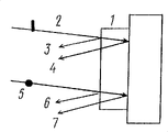
The principle of work of above-mentioned polaroid, be partly to be absorbed as the basis, thereby what pass through only is the part of light wave by the dye chromophore system with nonpolarized light by above-mentioned layer, wherein, the electric component orientation of oscillation of electromagnetic field is perpendicular to optical transition dipole moment (Fig. 4).
Be noted that to depend on used dyestuff, the polaroid of being protected is provided to provide not only by the polaroid in the visible part work of spectrum, and can be provided in the polaroid of UF zone and nearly IR regional work.Have under the situation of dichroic dye of absorption only using in the UF zone, birefringent layers can be used as phase delay layer.
Outstanding characteristics according to the polaroid of dichroic type of the present invention are, formed at least one birefringence anisotropy's absorption layer, this layer has the dyestuff and/or the water-fast dichroic dye of general formula (II-VI) and/or does not contain the pigment of the hydrophilic radical that generates ion.
The application of above-mentioned dyestuff, making can;
● improve polarization characteristic and form the flawless polaroid of high-level efficiency, the well-known polaroid ratio of this polaroid and patent WO 94/28073 (1994) except that having low conductivity, also has controlled LC capacity of orientation.
● make a polaroid, except showing excellent dielectric properties, also have high resistibility for humidity effect.
● widened the designs and varieties of the dyestuff that is suitable for making the high-level efficiency polaroid.
The dyestuff used with being used for making the polaroid learnt by patent WO 94/28073 (1997) is completely different, the application of above-mentioned dyestuff (II-VI) allows to adjust hydrophobic-hydrophil balance in the molecule of dichroic dye, this is mutually significant for forming lyotropic liquid crystal.Therefore, the foundation of some hydrophobic-hydrophil balance is to set up one of condition of the excessive molecular aggregates of these dye molecules.By means of this, when having reached a certain concentration of such gathering, solution just is transformed into orderly mesomorphic state.When under the LLC state, when by means of the orientation of carrying out simultaneously solution being applied on the face of substrate surface, just can form dielectric grid anisotropic absorption layer, the plane of the system of chromophore of dichroic dye molecule and be in optical transition dipole moment on this plane wherein, just be oriented with can by surface anisotropy be subjected to magnetic field or direction that the effect of electromagnetic field effects determines corresponding.
When the ion of using a kind of organic ion at least (dyestuff II-VI), can see a strong especially influence that comes from hydrophobic-hydrophil balance.Because this situation, non-organic, the dye solution that can not form the LLC phase under the form of symmetrical salt or acid also can obtain stable lyotropic liquid crystal phase for those.
For example, as the result of dyestuff and SUR condensation, formed associated matter has SUR character, and, assemble the formation agglomerate with the vesicle that forms, comprise non-coaxial form.
Depend on the number of organic group, depend on the mol ratio and the type of surface-active ion, the molecule of dichroic dye can be hydrophobic (polarity) component, and plays a part the hydrophobic part of SUR.Therefore, in the dichroic dye molecule, exist two kinds of groups that generate ions, and when above-mentioned dyestuff by with one mole surface-active ion condensation the time, formed is the surfactivity associated matter, wherein direct the and dye molecule of hydrophobic part associates.When the SUR condensation of the dichroic dye with the group that generates ion and a mole, just will produce associated matter, wherein, dye molecule will become the hydrophobic molecule part.More following examples that will provide various types of dyestuff various combinations, these dyestuffs have dissimilar surface-active ions and surfactant.As the result of such condensation, formed associated matter has SUR character, and, assemble the formation agglomerate with the micella that forms, comprise non-coaxial form.This dichroic dye molecule can be configured on the circumference and also can be configured within agglomerate or the micella.
Be configured under the inner situation at dye molecule, SUR alkyl (this is a kind of good directing agent of liquid crystal) will be positioned on the surface of birefringence anisotropy's absorption layer.By changing the structure of group, can improve the capacity of orientation of PC, this manufacturing for dissimilar LCI is important.
The existence of harmonic motion organic ion will produce low conductivity in the polarizing coating of the light polarization plate of being protected, and low conductivity will cut down the consumption of energy again conversely, therefore will prolong the serviceable life of liquid-crystal apparatus.
Surface-active property also provides the good wettable and the cohesive of LLC complex, and after being coated to such composition on the substrate surface, after drying, that produced is the PC with the flawless homogeneous that is no more than 5% thickness change.
The use of the dichroic dye (II-VI) that includes the group that generates ion or their potpourri and the associated matter of at least one mole surfactant or their potpourri make can control dichroic dye intramolecular hydrophobic-hydrophil balance, this control is important for some lyotropic liquid crystal mutually.Therefore, the foundation of some hydrophobic-hydrophil balance is to be used for forming one of condition of the excessive molecular aggregates of such dyestuff, and by means of this, when above-mentioned agglomerate reaches a certain concentration, solution just will be transformed into the mesomorphic state of ordering.
Owing to the solubilising phenomenon, be the character that the solubleness of water-fast fuel increases in water and in the water-soluble organic media based on one of speciality of the associated matter of dichroic dye with surface-active ion.This character allows to obtain polaroid, and in this polaroid, at least one birefringence anisotropy's absorption layer additionally contains the dyestuff after the dissolving.Depend on structure, the dipole moment of dissolving dye optical transition can be consistent with association dyestuff optical transition dipole moment, also can be on its a certain angle.This depends on the structure of surface-active ion, depends on the mol ratio of dyestuff again: the SUR in associated matter.
Except its effect is subjected to hydrophobic-hydrophil balance influences, the character of organic molecule, particularly surfactant will influence the stability of associated matter in different solvents consumingly, and this stability influences the size of agglomerate again conversely and forms LLC process mutually.
Therefore, two factors will be controlled the forming process and the type of LLC phase, promptly hydrophobic-hydrophil balance value and contain the group that generates ion or the dissolubility of the dyestuff associated matter with at least one mole organic ion and/or surface-active ion or their potpourri of their potpourri.Conversely, the degree of order of molecule also depends on the situation of the said mistake in top, thereby, depending on the polarization parameter of PC, this PC forms after the LLC compound is coated on the surface of substrate, and this surface has the solvent that then will remove.
At water-fast dichroic dye and/or do not contain on the basis that generates pigment ion or hydrophobic grouping or their potpourri; in birefringence anisotropy's absorption layer; the absence of ion; the high dielectric property matter of the polaroid of protecting providing; this will cause the reduction of energy consumption; thereby, the life-span of prolongation liquid-crystal apparatus.
The application of water-fast dichroic dye or pigment for form dielectric grid anisotropic absorption layer, except low conductivity, also provides high opposing for the influence of humidity.In addition, the manufacturing of the polaroid of being protected and comprehensive without any need for particular dye or pigment, commercial available dyestuff and pigment can utilize.
Dyestuff (II-VI) and/or do not contain the application that generates group ion or hydrophobic or the formed birefringence anisotropy's absorption layer of their potpourri makes and can produce heat-staple fast light polaroid:
● wherein, the form of the plate of at least one birefringence anisotropy's absorption layer or non-organic material organic with film is formed on the substrate surface.
● as substrate, it is made of birefringent plate or film, and the primary optical axis that at least one birefringence anisotropy's absorption layer is formed for above-mentioned plate or film becomes miter angle.
● wherein, at least one birefringence anisotropy's absorption layer is made of the part of two nonspecific forms at least, and these two parts are fully different each other aspect color and polarization axis direction.
● also comprise birefringence anisotropy's absorption layer at least, be contained in the part of at least two nonspecific shapes that these two parts are fully different each other aspect color and polarization axis direction.
● between birefringence anisotropy's absorption layer, also comprise a layer, this layer is material clear, colorless or that dyed look.
● also comprise an oriented layer that forms by non-organic material and/or various polymeric material.
● also comprise reflection layer.
● wherein, reflection layer is a metal level.
In order to make polaroid, wherein at least one birefringence anisotropy's absorption layer comprises at least 2 parts with nonspecific shape, this part is different aspect color and polarization axis direction, can use following technology: application of printed method (flexo-stenciling template on the layer of polarization phasor with homogeneous, embossment or photoeng raving), coated is with the figure of the form of the water-fast varnish of desired form.After the varnish sclerosis, clean the layer that exposes with suitable solvent (potpourri of water or water and organic solvent).Then, more other layer is coated on the substrate, this layer has different colors and polarization vector with fixing birefringent layers by above-mentioned varnish manufacturing.And then the layer of varnish of coating required form, by means of this, former figure still keeps being exposed on the outside.After sclerosis and back to back cleaning, just made the polarization figure, above-mentioned figure has the different colors and the part of polarization vector.
Adopt the different technology of applying the multiple roll printing, just can apply polychrome polarization figure according to ' scrolling turnover (roll-to-roll) ' technology.
The feasible form manufacturing polaroid that can paste polarization film with the oneself of use that replaces the various glue of varnish.Glue layer is with the form of figure; be attended by back to back birefringence anisotropy's absorption layer in any lip-deep transformation; on birefringence anisotropy's absorption layer, apply; can be used for making the protection of LC indicator with exterior arrangement polaroid and different types of trade mark or be used to obtain the color effect of device, for example the color effect in advertisement.Under the situation of the polaroid of the technology that make to adopt glue, opposite transformation also is possible: the glue layer of desired form is coated to the coating of the film of supporting coated birefringence anisotropy's absorption layer on the required surface, in the glue top and removes.Only the birefringence anisotropy's absorption layer corresponding to the glue layer form will be moved on the required surface from film surface.
Dyestuff (II-VI) and/or water-fast dyestuff and/or do not contain the use that generates group ion or hydrophobic or their potpourri apply the technology of birefringence anisotropy's absorption layer with making it possible to achieve layer to layer.As a result, can make by some one decks be added on another layer the polaroid that constitutes of birefringence anisotropy's absorption layer, each layer all is made of the part of some nonspecific shapes, these parts are all having nothing in common with each other aspect color and the polarization vector.
Before one deck of next of same dyestuff or other dyestuff can be applied directly on one deck, perhaps be coated on the middle layer of the transparent material after colourless or the dyeing.By means of this, secondly the direction of the polarization vector of one deck can be corresponding with the direction of the polarization axle of preceding one deck with any nonspecific form.
When polarized light flat in a polaroid rotates, can exist some zone to brighten and the situation of other zone dyeing (under the situation of monochromatic polaroid, wherein same color has different polarization vector directions).Under the situation of using different dyestuffs, in the rotation of polarized light flat, with the figure (in the zone of different color have the situation of identical polarization phasor orientation under) of existence with the varnish of the dyeing of different colors, the perhaps varnished part in succession of the different color that aspect polarization vector, differs from one another.The example of the said polaroid in top is in that to set up specific color effects field (advertisement, trade display window) interesting, is used to protect trade mark there and maintains secrecy.
Substrate surface in form dielectric grid anisotropic absorption layer, can be used different sublayers and further make amendment, and above-mentioned sublayer comprises photoactive layer, for example reflection layer, particularly diffusive reflective layer, birefringence or phase delay layer.Therefore, made is to be characterised in that to comprise the reflection layer that also can be used as conducting stratum in addition between substrate and polarizing coating.
When birefringent plate of 1/4 (quarter) ripple or film, for example polyvinyl alcohol (PVA) or polyethylene terephthalate are used as substrate, and, when the primary optical axis to substrate becomes miter angle coating birefringence anisotropy absorption layer, just can make a circular polarizing disk (Fig. 5 a and b are respectively the directions of normal and special ray, and n is the polarization layer polarization vector).The thickness of birefringent film must satisfy following requirement:
d(n
on
e)=λ/4+mλ/2,
Wherein, d is the thickness of thin polymer film, n
oAnd n
eBe normal and extraordinary refractive index, λ is a wavelength, and m is an integer.
When birefringence anisotropy's absorption layer is formed on thin polymer film (polyethylene terephthalate, polycarbonate, tri acetyl cellulose, other transparent thin-film material) top, can comprise that then the form of self-bonding glue film obtains polaroid with the polarization film of flexibility.
The polaroid of protecting in order to make can be used the different glue that comprises polyvinyl butyral, to produce various types of lamination structure structures, for example, makes auto industry and interested triplex glass of building or multilayer film.
Just as seeing, adopt the polaroid of dichroic type of the present invention, compare, except low conductivity, also show the high resistance of moisture effect and higher dichromatism ratio with the polaroid that adopts WO 94/28073 (1994) from table 1-3.
In addition, the polaroid of being protected has the character of homogeneous in its whole area, and one of standard of these character is the different thickness of birefringence anisotropy's absorption layer, is no more than 5%.
Table 1 is based on the characteristic of the light polarization plate of the organic salt of the dichromatism dye of positive ion of general formula (II)
| Number | Dyestuff | M | n | The thickness variance, % |
| 1 2 3 4 5 6 7 8 9 10 11 12 13 14 15 16 17 18 | Directly yellow, sun-proof O naphthalene-1,4,5, the disulphonic acid mixtures 3- |
(OHCH 2CH 2) 3NH HN 4* picoline NH 4* (OHCH 2CH 2OCH 2CH 2) 3NH NH 4* (C 2H 5) 4N NH 4* N-ethyl imidazol(e) Na* N-methylthiophene Na* NH 2(CH 2CH 2NH) 2CH 2CH 2NH 3 NH 4* [OH(CH 2CH 2O) 3CH 2CH 2] 2NH 2 NH 4* C 6H 5CH 2(CH 3) 3P NH 4* CH 3(C 3H 7)NH NH 4N-ethyl quinoline NH 4 C 6H 6(CH 3)NH 2Na* N-ethyl thiazole Na* [OH (CH 2CH 2O) 5CH 2CH 2] 2NH 2 NH 4* (C 4H 9) 3(CH 3)P NH 4* NH 2(CH 2CH 2NH) 4CH 2CH 2NH 3 NH 4* (OHCH 2CH 2OCH 2CH 2) 3NH NH 4* C 6H 5CH 2(CH 3) 3P NH 4* | 7 7 2 2 2 2 2 2 2 2 2 2 1 1 2 2 2 2 2 2 2 2 2 2 2 2 4 4 2 2 - - | 5 15 5 18 (important scatterings), 3 10 5 15 (scattered lights) 5 15 5 15 5 15 5 15 5 10 5 15 5 15 5 20 5 18 5 15 5 10 5 15 5 15 5 18 |
Known polaroid according to patent WO 94/28073 (1994) D
Table 2
| Number | Dyestuff | General formula | Dichromatism ratio D
i/ |
| 1 | Directly yellow, sun-proof O | f=g=0;X=X’=SO 2 M=(OHCH 2CH 2) 3NH;n=3;M 1=NH 4;m=3;(I)*,M=NH 4;n=6 | 15.0 10.0 |
| 2 | Naphthalene-1,4,5, the disulphonic acid mixtures of the bisbenzimidazole of 8-tetracarboxylic acid | F and g=0, X=X '=SO 2;n=1;M=(OHCH 2CH 2OCH 2CH 2) 2NH 2;M 1=NH 4;m=1(I)*,M=NH 4;n=6 | 16.0 10.0 |
| 3 | 3- |
F and g=0, n=1; X=X '=SO 2,n=2;M=Cs;m=1;M 1=NH 4,(I)*,M=NH 4,n=6 | 35.0 23.0 |
| 4 | C.I. direct yellow 73 | F and g=0; X=SO 2, n=2; The M=N-picoline; M=2; X '=CO, M 1=NH 4(I)*,M=NH 4,n=4 | 14.0 8.0 |
| 5 | The trisulfonic acid (peony) that sulfo-is indigo | F and g=0, X=X '=SO 2 M=octyl group ammonium; N=1; M 1=Na;m=2;(I)*,M=NH 4,n=3 | 16.0 0 |
| 6 | Perilene-3,4,9, the potpourri of the sulfonic acid of the bisbenzimidazole of 10-tetracarboxylic acid | F and g=0, n=1; X=X '=XO 2 The M=N-methylthiazol; M=1; M 1=NH 4,(I)*,M=NH 4,n=2 | 17.0 10.0 |
| 7 | Acid high blue anthraquinone | F and g=0; N=1; X=X '=SO 2;M=(NH 2CH 2CH 2NHCH 2CH 2) 2NH 2;m=1;M 1=NH 4;(I)*,M=NH 4,n=2 | 18.5 3.0 |
| 8 | The active light blue of C.I.43320 | n=m=0;X=X’=SO 2;Z=NH,p=1;M=(OHCH 2CH 2) 3NH;f=1;M 1=NH 4;g=1;(I)*,M=NH 4,n=2 | 19.0 2.0 |
| 9 | Active brilliant violet | f=0;n=2;X=SO 2;M=NH 4;m=0;Z=SO 2;p=2;X=OSO 2;M 1=K;g=1(I)*,M=NH 4,n=3 | 15.0 2.0 |
| 10 | Active bright light blue 2KT | f=0;n=1;X=SO 2;M=(OHCH 2CH 2) 3NH;m=0;g=1;Z=SO 2;p=2;X=OSO 2;M 1=NH 4;(I)*,M=NH 4,n=3 | 16.0 5.0 |
| 11 | Reactive yellow 13-181 | n=0;f=1;Z=SO 2NH,p=2;X=X’=OSO 2;M=(OHCH 2CH 2) 3NH;m=0;g=1;M 1=NH 4;(I)*,M-NH 4,n=2 | 14.0 3.5 |
| 12 | The acid black 3M of C.I.14865 | F and g=0, X=X '=SO 2;M 1=N-methylthiazol; N=1; (I) *, M=NH 4;m=1;(I)*,M=NH 4,n=2 | 15.0 3.0 |
Characteristic based on the light polarization plate of the asymmetric potpourri of the dichromatism dye of positive ion of general formula (III)
The polaroid of learning by patent WO 94/28073 (1994)
Table 3 is based on the characteristic of the light polarization plate of the associated matter of the dichroic dye that comprises the group that generates ion of general formula (IV-VI) and surfactant
| Number | Dyestuff | General formula | Conductance * 10
-10ohm
-1 |
| 1 | Direct yellow sun-proof O | (IV), SUR-dodecyl ammonium, X, X '=SO 2;n=1;M=NH(C 2H 4OH) 3;m=6 (I)*,m=7;M=NH 4 | 0.115.0 |
| 2 | Indigo disulfonic acid (indigo plant) | (IV), SUR-decyl trimethyl ammonium kation; X, X '=SO 2;n=1;M=Na;m=1; (I)*,M=NH 4,m= 2 | 0.510.0 |
| 3 | Indigo two trisulfonic acids of sulfo-(peony) | (IV), SUR-decyl pyridylium; X, X '=SO 2 N=1; The M=N-picoline; M=2; (I) *, M=NH 4, m=2-PC can not obtain | 0.05 - |
| 4 | C.I. direct orange 138 | (IV), SUR-octyl group trimethyl kation; X, X '=SO 2;n=1 M=NH(C 2H 4OH) 3; m=1; (I)*M=NH 4,m=2,n=0 | 0.04 13.0 |
| 5 | C.I. reactive yellow 1 | (IV), SUR-dodecyl ammonium cation; X=X '=SO 2;n=1;M=NH(C 2H 4OH) 3; m=1; (I)*,M=NH 4,m=2;n=0 | 0.05 15.0 |
| 6 | C.I. Indian yellow 135 | (IV), the triethanolamine salt of SUR-dodecyl dimethyl aminoacetic acid; Z=0; P=2; X=OSO 2;n=1;m=0; (I)*,M=NH 4,m=1,n=0 | 0.5 20.0 |
| 7 | C.I. direct yellow 73 | (IV), SUR-dodecyl glyoxaline cation; X=SO 2;n=2;X’=CO,M=Ba, m=2; (I)*,M=NH 4,m=4,n=0 | 0.5 20.0 |
| 8 | C.I. active brilliant violet IT 73 | (IV), SUR-cetyl trimethyl ammonium kation; Z=NH, p=1, X=SO 2,f=1,n=0; X’=SO 2,M=Cs’;g=1;m=0; (I)*,M=NH 4,m=2,n=0 | 0.3 25.0 |
| 9 | The C.I.63320 acid brilliant blue | (IV), SUR-dodecyl glyoxaline cation; Z=SO 2,p=2,X=OSO 2,f=1, n=0;X’=SO 2,M=Na,m=2;g=0, (I)*,M=NH 4,m=3,n=0 | 0.7 20.0 |
| 10 | The C.I.50315 cloth fast blue r | (V), SUR-octyl sulfate; G=0, m=2; X=SO 2,M=NH 4; | 1.0 |
| 11 | C.I.44025 acid green Zh | (V), SUR-lauryl sulfate; G=0; M=2; X=SO 2,M=NH 4; | 0.5 |
| 12 | C.I. alkali blue 41 | (VI), SUR-2-hydroxyl-3-(dodecyl trimethyl ammonium)-propane sulfonic acid salt, triethanolamine salt; N=1 | 0.5 |
| 13 | C.I. alkali blue 4 | (VI), SUR-2-(dimethyl octyl group acylamino-propyl ammonium) ethylsulfate, N-picoline; N=1 | 0.2 |
| 14 | Methylene blue | (VI), the dimethyl dodecyl ammonium of SUR-acetate, triethanolamine salt; N=1 | 0.5 |
| 15 | C.I. alkalescence 22 | (VI), SUR-octyldimethyl ammonium ethane sulfate, ammonium salt; N=1 | 1.0 |
* the polaroid of learning according to patent WO 94/28073 (1994)
Should be pointed out that the top mentions based on the dichromatism of birefringence anisotropy's absorption layer and the polaroid of interfere type, all have a refractive index that increases along with the increase of wavelength at least, suppose that the utilization of incident optical energy is not more than 50%.
Application with birefringent layers of unusual chromatic dispersion also makes, and a kind of polaroid that the radiation source of the nonpolarized light that in fact enters is converted to polarized radiation that provides can be provided.
The polaroid of being recommended of the above-mentioned type comprises:
Be used for the nonpolarized light light beam of the incident light on numerous formation polaroids be divided into same numerous differently polarization the polarized light light beam identical right polarization member and
Be used for changing the parts of polarization of the polarized light light beam of at least a numerous polarization in the same manner, above-mentioned polarized light light beam is made up of the polarized light light beam of above-mentioned numerous paired differently polarization.
The above-mentioned polarization member made from the form of focusing optical element (each element all has birefringence anisotropy's absorption layer that at least one and light isotropic layer adjoin) carries out optical location with parts that the form with the translucent birefringent plate of slice type (sectioned) of above-mentioned change polarization is made and aims at.
For for simplicity, above-mentioned polaroid will be counted as the polaroid based on the transmission-type polarization member.
The characteristics of this polaroid also are the application of at least one birefringence anisotropy's absorption layer in above-mentioned polarization member, and this birefringence anisotropy's absorption layer has the refractive index that increases along with the increase of polarized light wavelength.
The focus optics of the above-mentioned polaroid of protecting can be made with the form of zone plate (zone); in Qi Quan (turn); can make with the form of amplitude (amplitude) zone plate; wherein; the zone plate of even number is made of birefringence anisotropy's absorption layer that is adjacent at least one light isotropic layer at least, and the zone plate of odd number is made with the optics isotropic material.
The phase place zone plate can be used as the another kind of polaroid of being protected.
The phase place zone plate can have at least one refractive index, and this refractive index changes along at least one direction (comprising the direction along plate).
At least one refractive index of phase place zone plate can change according to a certain rule that comprises nonmonotonic variation on the direction of board plane.
The parts that are used for changing the polarization of the polaroid of being protected also comprise transparent birefringence anisotropy's absorption layer of a slice type, and this absorption layer has at least one refractive index that increases along with the increase of polarized light wavelength.
In polaroid based on the transmission-type polarization member, at least one refractive index of at least one birefringence anisotropy's absorption layer, can be directly and polarized lightwave grow up to direct ratio.
At least one birefringence anisotropy's absorption layer of the polaroid of being protected can have such thickness, therein, can realize interfering extreme value for a linear polarization light component at least in the output of polaroid.By means of this, for a linear polarization light component by light, the thickness of at least one birefringence anisotropy's absorption layer can satisfy the minimizing condition of acquisition interference in the output of light polarization plate, then satisfies the maximum value condition for another orthogonal linear polarisation light component by light.
The polaroid of protecting in order to make, can select layer in this wise: the light isotropic layer will be identical or extremely approaching with a refractive index of birefringent layers.
The polaroid that preferred feature is following: be used for changing the parts of polarization, be with the transparent half wave double deflecting plate of slice type have in focus the inside of focusing optical element or the section (section) of the outer configuration of focus layer form make.
In the parts that changing polarization, when used is ' achromatic ' half-wave or 1/4 ripple (for circular polarizing disk) plate, wherein, phase lag (or optical path difference) is a half-wave or 1/4 wavelength, when light passes through such plate, polarization all will take place in all wavelength in working range change.
Another embodiment is such polaroid, it is characterized in that: polarization changes parts and makes with the form of the transparent birefringent plate of slice type, this plate has the outer section of focus that form with 1/4 wavelength plate is configured in the focusing optical element, and is configured in the section inside the focus of focusing optical element with the form of the plate that determines phase differential (differing from a π with the phase differential with above-mentioned part decision) between normal and special ray.
Be used for changing the parts of the polarization of the polaroid of being protected; can send out form with the slice type transparent polymeric materialization plane layer with twist structured liquid crystal makes; wherein; liquid crystal optic axis within the thickness of above-mentioned layer is orientated 90 degree, has inside the focus that is configured in the focusing optical element and the section outside the focus.
The polaroid of being protected; can make with the form of film or plate; this film or plate comprise above-mentioned polarization member with the form of focusing optical element; these parts all have different focus power to each component that is input to the nonpolarized light on the polaroid, and carry out optical location with the parts of the polarization of the above-mentioned polarized light light beam that is used for changing at least one numerous polarization in the same manner and aim at.Above-mentioned focusing optical element can be volume (volume) or phase place collecting lens, or from zone plate optics [referring to G.S.Landberg, Optics, rev.and suppd. the 5th edition., ' Nauka ' publishers, Moscowa, 1976] their the various known kind learnt.
The polaroid of being protected is (for this polaroid; the wavelength coverage of observing anomalous dispersion is different with operating wavelength range) be such polaroid: constitute by birefringence anisotropy's absorption layer at least, represent numerous volume (volume) or phase place lens.In this case, be used for forming the way of the suitable dyestuff of said lens, the polaroid of polarization just might be provided in the IR zone.
Should be pointed out that the focusing optical element not only can have the form of lens, also can have the form of catoptron and the form of combination.
Outstanding characteristics of the present invention are, at least use birefringence anisotropy's absorption layer in order to make polaroid with anomalous dispersion, this absorption layer is made of polarization member, and, provide at the embodiment that is used at least a polarized light component is changed some devices of polarization.
For forming above-mentioned birefringence anisotropy's absorption layer, can use those materials and the technology that the polaroid that is provided with the interference protected and dichroic type uses with anomalous dispersion.
The embodiment that discuss the top does not limit uses other material for the form dielectric grid layer of the light polarization plate use of being recommended.
The Technology Selection that applies directed birefringent material depends on used material, and for the invention essence be unessential.According to the polarization layer of birefringent material of the present invention not only can be that smooth layer for example also can be, the focus layer that forms with the form of lens and/or catoptron.
Photoetching technique can be used for setting up the slice type birefringent layers.In order to apply thermotropic polymeric material, can use extruder, comprise that those have (10-100) flat-die and permission many different polymeric material desired thickness several layers of coating in once operating in a large number.
The end product of any employed technology all must be the oriented layer of birefringent material, this oriented layer except refractive index changing on the different axles, also have dichromatism, and have the optimum value of absorptivity.
The principle of work of the polaroid of being protected can be described below.Nonpolarized light light incides on the 1st the smooth surface of polaroid, is added in a polarization member of its top with the form formation of film or plate.Above-mentioned nonpolarized light light, the form that has different focus power with each polarized light component for the incident nonpolarized light is by polarization member, is divided into light beam numerous right of polarization differently.Meanwhile, the light beam of resulting differently polarization numerous right is the colony of two kinds of light beams, and wherein, in each colony, for all light beams that are made of above-mentioned colony, this light all is being polarized in the same manner.In addition, one of colony of these light beams that constitute by the polarized light of above-mentioned differently polarization, can have for example form of parallel beam polarized light in same plane, another light beam colony for example then can have in this plane the form perpendicular to the linear polarization of light beam of the plane of polarization of the light beam of the 1st colony, the light of the 1st colony converges on the focus of focusing optical element, this focus is disposed on the 2nd flat surfaces of polaroid regularly, and what the 2nd surface comprised that the form with the transparent birefringent plate of slice type is added in its top is used for changing the parts of the polarization of a colony of the light beam of polarization at least comparably.At least one colony of the light beam of polarization in the same manner, change component configuration on the 2nd surface of polaroid by above-mentioned polarization, and change its polarization in this wise: make its polarization state will with the also polarization and also to have passed through the polarization polarized state of light of the 2nd boundary surface of polaroid identical in the same manner of another colony.The result, above-mentioned two light beam colonies of leaving based on the polaroid of the polarization member of transmission-type become and are polarization in the same manner, and, the leaving polaroid of above-mentioned light beam and two colonies going are delivered to the luminous energy total amount that incides on the polaroid more than 50% at least, and be in same direction basically.
Another type of being protected polaroid greater than 50% the conversion of inciding the whole luminous energy on the polaroid is provided, be polaroid based on the reflection type polarization parts.
Above-mentioned polaroid is to make with the form of at least one film or plate, what use in this film or plate top is, be used for the incident nonpolarized light is converted to the parts of the colony of identical light beam, one be used for non-polarized light beam be divided into polarization with different polarizations by light beam and folded light beam parts and be used for changing the polarization that is polarized the parts beam reflected and the parts of direction.
An outstanding feature of the polaroid of being protected is such polarization member; this device is made of birefringence anisotropy's absorption layer that at least one has at least one refractive index that increases along with the increase of polarized light wavelength; perhaps; birefringent layers by the optical axis of constant direction (pass layer thickness) constitutes, and the rule that above-mentioned optical axis is abideed by regulation changes (thickness that passes layer).
Depend on the type of employed birefringent layers, the division of non-polarized light beam can be divided into linear polarization by light beam and have the folded light beam of cross polarization, perhaps is divided into circular polarization by light beam with have the folded light beam of opposite polarization rotation symbol.
Be used for changing the polarization of folded light beam of the polaroid of being protected and the parts of direction and can comprise a slice type metal (reflection) mirror.
Preferred such polaroid, its polarization member comprises at least one birefringence anisotropy's absorption layer or has the birefringent layers of the optical axis of constant (passing layer thickness), and is equipped with 1/4 wavelength plate in the upstream of slice type speculum.
In addition, preferred such polaroid comprises at least one the birefringence anisotropy's absorption layer with at least one refractive index that increases along with the increase of polarized light wavelength.
In addition, preferred such polaroid wherein, can be observed the anisotropic absorption of birefringent layers, thereby satisfy the wavelength region may of the condition of anomalous dispersion, conforms to the wavelength perform region.
The most preferably application of birefringence anisotropy's absorption layer, this layer have at least one directly and polarized lightwave grow up to the refractive index of direct ratio.
Polaroid of the present invention can comprise at least one birefringence anisotropy's absorption layer, the layer that the material that is used for making the interferential polarizers of being protected forms.
The embodiment that discuss the top does not limit the application of other the material that is used to form the birefringence anisotropy's absorption layer that uses for the polaroid of being recommended.
In the polaroid of being recommended, birefringence anisotropy's absorption layer both can be solid also can be liquid.
In order to make birefringent layers, can use with the thin polymer film of single shaft or twin shaft tension force orientation, the thin polymer film of transparent in the operation wavelength zone (not absorbing light) with constant (passing the thickness of layer) optical axis direction.
An example with the birefringent layers of abideing by a certain rule change (passing the thickness of layer) optical axis direction is the cholesteryl liquid crystal layer.In such layer, corresponding to the major axis of rodlike molecule thereby be equivalent to the optical axis of bigger refractive index, in intelligence (mental) motion, pass layer thickness, keep parallel with layer plane.Pass the distance (optical axis carries out the rotation fully of 360 degree there) of thickness, preferred cholesterol screw pitch.The optical axis sense of rotation both can be clockwise, and the preferred dextrorotation of above-mentioned spiral, also can be anticlockwise, and above-mentioned spiral was left-handed.Such structure (structure) of the birefringent layers of cholesteryl liquid crystal, preferred planar the sort of, perhaps dextrorotation Granjean structure.The main character of the birefringent layers of the cholesteryl liquid crystal of planar structure is as follows.
1, incide when layer last when light, the selection reflector space of a light is arranged, the spectrum that is arranged in this zone is proportional to the cholesterol screw pitch.
2, the light spectral width of selecting reflector space and refractive index anisotropy (promptly between normal and extraordinary refractive index poor) are directly proportional.
3, select within the reflector space at light, a circular component consistent with cholesterol spiral sense of rotation reflected fully, and another circular component of nonpolarized light (direction of this component is opposite with cholesterol spiral sense of rotation) is then fully by this layer.
Therefore, planar structure cholesteryl liquid crystal layer is for all being reflective circular polarizing disk by light and reflected light.Layer like this can be used as polarization member or is included in the polarization member, be used for non-polarized light beam be divided into have different polarizations pass through light beam and folded light beam.When being necessary, can be used for well-known 1/4 ripple plate to convert circular polarization to linearly polarized photon.
Preferably according to polaroid of the present invention, the polarization member of this polaroid comprises at least one cholesteryl liquid crystal layer.
More preferably according to polaroid of the present invention, this polaroid comprises the cholesteryl liquid crystal that at least one is made by the polymkeric substance cholesteryl liquid crystal.
At least one cholesteryl liquid crystal has the gradient of a cholesterol screw pitch of passing its thickness, and as a result of, has the spectral width that the light that is no more than 100nm is selected the zone of reflections.
The polarization member of reflective polarizer can comprise that at least 3 layers have the cholesteryl liquid crystal that light is selected the zone of reflections in 3 different SPECTRAL REGION.
The input nonpolarized light is converted to the parts of numerous identical light beams, can make with the form of microlens system or the form of microprism system, said system focuses on the light beam that is input to its top on the direction of the inside of polaroid.Particularly microlens system can be made with the lenticular form of the right cylinder that covers the polaroid surface fully.
The Technology Selection that is used for polaroid constructed in accordance depends on the material that uses for birefringent layers and is unessential for the present invention.
In order on the surface of the polaroid of being recommended, to form the polarizing coating that comprises at least one birefringent layers, can use following standard method: adopt the way of molding to make directed in advance thin polymer film carry out lamination; Under liquid state,,, apply employed material with non-rotating cylindrical form with roller, scraper, blade; Use the coating of slit die and other method.In some cases, after coating, attempt to remove solvent.In other cases, for example,, after coating, cool off coated layer for thermotropic material and vitrifacation material.
Can be used for obtaining those other technology, comprise such material is coated to the substrate top that this substrate is [the US patent 2525286 (1950)] that is ready in advance the liquid crystal phase orientation when the birefringent layers of the material that after use, forms liquid crystal phase.One of these technology are unidirectional rubbed substrates, or friction is coated to the thin polymeric layer of its top in advance, and the latter is well-known and is used for making the directed thermotropism low molecular weight liquid crystal of LC display potpourri.
The other technology that is used for obtaining birefringent layers is well-known layer with the coating in advance of this or the sort of form to be carried out the technology of light orientation, and this technology adopts linear polarized uv to shine.
In order to apply the birefringent layers of thermotropism polymeric material, can use extruder, comprise extruder, and allow at the layer of the different polymeric materials of which floor desired thickness of coating in service once with many flat-dies.
Layer for the cholesteryl liquid crystal of making planar structure, can use following material: cholesterol ester, the nematic liquid crystal after mixing with Photoactive compounds, so-called chirality are to row (wherein the photolytic activity center is carried out chemistry and is connected with nematic liquid crystal, polymkeric substance cholesteryl liquid crystal, the molten molecule that causes cholesteryl liquid crystal of for example polypeptide and cellulose ether).
The layer of manufacturing can be liquid state or solid-state.The curing of layer can be adopted the way that reduces temperature, adopts and make solvent evaporation, comprises that photoinduction is aggregated in interior polymerization way and carries out.
Parts as the incident nonpolarized light being converted to numerous identical light beams, can use: a microlens system, no matter be volume or plane Frensnel lens; And the other system that is used for focused beam; With volume prism (for example leg-of-mutton) or plane prism (for example having distributed refractive index of passing thickness and surface); The parts that are used to make the light reflection that also have other.
In order to make lenticule or microprism system, can use die casting, foundry engieering, for example, in the thin polymer film of polymeric material, fill the depression of the desirable shape of preprepared with bigger refractive index; Photoinduction polymerization and other technology.
In order to apply a slice type speculum, can use following standard method: thermal evaporation in a vacuum, coating is also heat-treated in succession in steam, magnetron sputtering and other method.In order to apply catoptron, can use aluminium (Al), silver (Ag) and other metal.
That is protected will illustrate in the narration of the specific example of this polaroid based on the principle of work of the polaroid of reflection type polarization parts.
Mention with regard to di sopra, the above polaroid of being protected can particularly use in comprising the liquid crystal display cells of flat-panel monitor at the device of various display message.
The objective of the invention is to improve the image that produces with liquid crystal display cells brightness and color saturation are provided.
Adopt the way of using liquid crystal display cells (LCI), this purpose can realize, above-mentioned liquid crystal display cells is made of liquid crystal layer and the polaroid between the 1st and the 2nd plate, at least one above-mentioned plate is an electrode, above-mentioned polaroid comprises birefringence anisotropy's absorption layer at least, and this absorption layer has at least one refractive index that increases along with the increase of polarized light wavelength.
In order to form above-mentioned layer, material and technology identical materials and technology that the polaroid that uses and be provided with being protected uses.
Adopt to comprise a LCI element at least, just can provide high-quality image with reflective polarizer of high polarization characteristic.
The LCI element of being protected can also comprise that on a plate diffusive reflective layer (this layer is an electrode simultaneously) and at least one this layer of birefringence anisotropy's absorption layer directly are positioned on the reflection horizon, perhaps is coated on the dielectric sublayer of reflectance coating top.
The feature of the other embodiments of LCI element is: on an above-mentioned plate, form an extra play of colour cell between polaroid and plate.
The polaroid of the LCI element of being protected can also comprise at least one reflection horizon, and this reflection horizon is reflection ray at least in part.Above-mentioned reflection layer can be made with metal.
At least one birefringence anisotropy's absorption layer of at least one polaroid of the LCI element of being protected can be to make in the form of elements different aspect phase delay and/or the polarization axis direction.
A polaroid of the LCI element of being protected is made of birefringence anisotropy's absorption layer of two different colours at least, and this absorption layer has orthogonal polarization axis direction, and one in another top, perhaps on their at least one middle layer separately; On another plate, polaroid comprises birefringence anisotropy's absorption layer of a grey at least, and this absorption layer has the consistent polarization axle of polarization axis direction of one of birefringence anisotropy's absorption layer with on the 1st plate.
Based on the utilization of reflection type polarization parts use, high brightness is provided and has reduced the amount of power consumption of LCI components consume greater than the polaroid of 50% nonpolarized light.
The LCI element of being recommended comprises the liquid crystal layer between the 1st and the 2nd plate, and there, there are electrode and polaroid in one of above-mentioned at least plate top.At least one polaroid comprises:
Be used for numerous non-polarized light beams that incides the light on the polaroid is divided into the identical right parts of the light beam of same numerous differently polarization, these parts are made with the form of focusing optical element, each element all comprises at least one birefringence anisotropy's absorption layer, this absorption layer has a refractive index that increases along with the increase of polarized light wavelength at least and adjoins with at least one light isotropic layer, above-mentioned polarization member be used for changing at least one in the same manner the parts of the polarization of the light beam of polarization (by the light beam of polarization differently above-mentioned numerous) to constituting carry out optical location and aim at.
At least one birefringence anisotropy's absorption layer of the focusing optical element of the LCI element of being protected can be realized with numerous volumes or phase place lens.
The focusing optical element of the LCI element of being protected can be realized with the form of zone plate.
A kind of zone plate is a wide cut degree zone plate, and the zone plate of its even number comprises birefringence anisotropy's absorption layer that at least one and at least one light isotropic layer adjoins, and the zone plate of odd number is made of the light isotropic layer.
Another kind of zone plate is the phase place zone plate.
Be used for changing the parts of the polarization of LCI element, can comprise the transparent birefringence anisotropy's absorption layer of slice type with at least one refractive index that increases along with the increase of polarized light wavelength.
Polarization changes parts, can be with the transparent half wave double deflecting plate of slice type or form with layer of the outer section of the focus that is arranged in the focusing optical element or focus make.
The polarization of the polaroid of the LCI element of being protected changes parts; can be to have focus or the outer section of focus that is arranged in the focusing optical element with the form of 1/4 ripple plate; and the form of the transparent birefringent plate of slice type that has between normal and special ray the section of decision phase differential is made, above-mentioned phase differential with differ from a π with above-mentioned section with the phase differential that the form of 1/4 ripple plate of the focus that is arranged in the focusing optical element determines.
The polarization of the LCI element of being protected changes parts; can be to have distorted-structure; and have within the thickness of above-mentioned layer liquid crystal optic axis and revolve and turn 90 degrees, the form of slice type transparent polymeric materialization plane layer that also has the liquid crystal of the outer part of the focus that is arranged in the focusing optical element or focus is simultaneously made.
The polarization of the LCI element of being protected changes parts, can make with the form of the transparent achromaticity birefringent plate of slice type.
Adopt use brightness to be increased and the reduction power consumption based on the LCI element of the polaroid of reflection type polarization parts.
The LCI element of being recommended comprises a liquid crystal layer between the 1st and the 2nd plate, has electrode and polaroid at least one plate.At least one polaroid is made with the form of at least one film or plate, is added with in the top of film or plate: the parts that are used for the incident nonpolarized light is converted to numerous identical light beams; Be used for non-polarized light beam and be divided into polarization with different polarizations polarization member by light beam and folded light beam, these parts comprise that at least one has refractive index birefringence anisotropy's absorption layer that at least one increases along with the increase of polarized light wavelength, perhaps birefringent layers, this birefringent layers has such optical axis direction, and this direction is deferred to a certain rule (passing layer thickness) and changed; With change be polarized the parts folded light beam polarization and the parts of direction.
Be used to change the polarization of folded light beam of the LCI element of being protected and the parts of direction and can comprise the slice type speculum.
The polarization member of the LCI element of being protected can comprise at least one birefringence anisotropy's absorption layer or birefringent layers, and this birefringent layers has the optical axis direction of constant (passing layer thickness), and has 1/4 ripple plate in the upstream of slice type speculum.
The polarization member of the LCI element of being protected can comprise: at least one birefringent layers, this birefringent layers have defers to the optical axis direction that a certain rule (passing layer thickness) changes; At least one cholesteryl liquid crystal, this liquid crystal can be made with the polymkeric substance cholesteryl liquid crystal.
One deck at least of cholesteryl liquid crystal can have (passing layer thickness) cholesterol screw pitch, thereby, have the spectral width that the light that is not less than 100nm is selected the zone of reflections.
Polarization member can comprise at least 3 layers of cholesteryl liquid crystal, and these liquid crystal have light and select the zone of reflections in 3 different SPECTRAL REGION.
Being used for of the LCI element of being protected changed the parts of the incident nonpolarized light of polaroid, can make with the form of microlens system or microprism system, and this system focuses on direction towards the inside of polaroid to the light beam that leaves it.
A lenticular system can make with the lenticular form of the right cylinder that covers the polaroid surface fully.
On the 1st surface of film or plate, the polaroid of the LCI element of being protected can comprise microlens system and carry out the slice type speculum aimed at optical location with above-mentioned microlens system; On the 2nd surface of film or plate, can comprise one deck cholesteryl liquid crystal at least.
The polaroid of the LCI element of being protected on the 1st surface of film or plate, can comprise a microlens system, a slice type speculum that carries out aiming at optical location with above-mentioned microlens system, one 1/4 ripple plate; Also comprise at least one birefringence anisotropy's absorption layer or birefringent layers on the 2nd surface of polaroid, this birefringent layers has constant (passing layer thickness) optical axis direction.
Polaroid on the 1st surface of film or plate, can also comprise a slice type speculum, and on the 2nd surface of film or plate, coating is successively: carry out the microlens system aimed at optical location and one deck cholesteryl liquid crystal at least with the section of speculum.
Preferred such LCI element, its polaroid comprises a slice type speculum and one 1/4 ripple plate on the 1st surface of film or plate, on the 2nd surface of film or plate successively coating be: carry out the microlens system aimed at optical location and at least one birefringence anisotropy's absorption layer or birefringent layers with speculum, this birefringent layers has constant (passing layer thickness) optical axis direction.
The polaroid of the LCI element of being protected can comprise at least two lamination type films or plate; What apply on the outside surface of the 1st film or plate is the 1st microlens system, what apply on the inside surface of the 1st or the 2nd film or plate is the slice type speculum, and additional coating is to carry out the 2nd microlens system that optical location is aimed at the section and the 1st microlens system of speculum on the outside surface of the 2nd film or plate; At least one deck cholesteryl liquid crystal.
Preferred such LCI element, its polaroid comprises at least two lamination type films or plate; What apply on the outside surface of the 1st film or plate is the 1st microlens system, what apply on the inside surface of the 1st or the 2nd film or plate is slice type speculum and 1/4 ripple plate, additional coating is to carry out the 2nd microlens system that optical location is aimed at the section and the 1st microlens system of speculum on the outside surface of the 2nd film or plate, at least one deck birefringence anisotropy absorption layer or birefringent layers, this birefringent layers has constant (passing layer thickness) optical axis direction.
The polaroid of the LCI element of being protected can comprise at least two lamination type films or plate; what apply on the outside surface of the 1st film or plate is microlens system; what apply on the inside surface of the 1st or the 2nd film or plate is the slice type speculum of aiming at the optical location of microlens system; on the outside surface of the 2nd film or plate, coating be one deck cholesteryl liquid crystal.
Preferred such LCI element, its polaroid comprises at least two lamination type films or plate; What apply on the outside surface of the 1st film or plate is the 1st microlens system, on the inside surface of the 2nd film or plate successively coating be to carry out slice type speculum and the 1/4 ripple plate aimed at optical location with microlens system; What apply on the outside surface of the 2nd film or plate is one deck birefringence anisotropy absorption layer or birefringent layers at least, and this birefringent layers has constant (passing layer thickness) optical axis direction.
Preferred such LCI element, its at least one polaroid also comprise with non-organic material or the oriented layer that forms on the basis of polymeric material.
Oriented layer can be formed at birefringence anisotropy's absorption layer top, or is formed between substrate and the above-mentioned layer.
Other embodiments are a kind of LCI elements, it is characterized in that: at least one plate top, at least one birefringence anisotropy's absorption layer of at least one polaroid is in the transparency electrode top or between plate and electrode, perhaps be located at the electrolytic thin-membrane top of covering transparent electrode or between the layer and the electrolyte sublayer of coated electrode of directional crystal, perhaps in the top of the opposite side of layer.
Preferred such LCI element, it is characterized in that: what form on a plate is the scattered reflection coating that can be used as electrode simultaneously, with at least one birefringence anisotropy's absorption layer, this absorption layer is located immediately at the reflectance coating top or is coated in the dielectric layer top of reflectance coating top, perhaps be positioned at the layer of location liquid crystal and be coated to other one deck of reflectance coating top weary between.
At least one birefringence anisotropy's absorption layer in the embodiment that is coated on the LCI element of mentioning all tops, can have at least one directly and polarized lightwave grow up to the refractive index of direct ratio.
At least one birefringence anisotropy's absorption layer of at least one polaroid can have such thickness in the embodiment of the LCI element of mentioning in all tops, in this thickness, in the output of polaroid,, will realize interfering extreme value at least for a polarized light component.
The thickness of at least one birefringence anisotropy's absorption layer of at least one polaroid of the LCI element embodiment of mentioning in all tops, in polaroid output, can satisfy obtaining interfering minimizing condition, then can obtain interfering maximum value for another orthogonal linear polarisation light component for a linear polarization light component.
In the embodiment that comprises two-layer at least LCI element that all tops are mentioned, at one deck at least wherein, comprise birefringence anisotropy's absorption layer, and another layer is the light isotropic layer, the refractive index of this layer is consistent or very approaching with a refractive index of birefringent layers.
In the embodiment of the LCI element of mentioning in all tops that comprises two-layer at least birefringent layers, at one deck at least wherein, comprise the anisotropic absorption layer, a refractive index of this anisotropic absorption layer is consistent or very approaching with a refractive index of birefringent layers, and the 2nd refractive index of birefringent layers and birefringence anisotropy's absorption layer differs from one another.
In LLC forms, adopt the way that used dyestuff is changed, just can obtain having the LC device of the different colours that comprises grey.Adopt the way of yellow, the red and blue birefringence anisotropy's absorption layer of coating successively, when they are formed on the plate of plate, also can obtain grey.
Use comprises the associated matter of the dichroic dye of the group that generates ion and at least one mole organism (especially for the surface-active ion of form dielectric grid anisotropic absorption layer), when polaroid is positioned at the LCI element internal, to provide the good capacity of orientation of polaroid, thereby can avoid applying necessity of additional directed LC layer.Employing makes the way of the structural change of organic ion, in making polaroid, can change the orientation and the wetting power of solution, and this change is important for the manufacturing of various types of LCI elements.
In addition, the existence of harmonic motion organic ion in polarizing coating provides low conductivity, and this low conductivity cuts down the consumption of energy again conversely, therefore, prolonged the serviceable life of liquid-crystal apparatus.By means of this, when polaroid is positioned at its inside, just can avoid applying necessity of additional insulation course.
The dyestuff that adopts most of dissimilar dyestuffs for example to have formula (II-VI) is made polaroid, and the variability of the color alignment of the LCI element of being protected just can be provided.
Use on the surface of the whole LCI that protects, provides high brightness and good angular characteristics, and for reflection, does not have shade at work based on the interference polaroid of birefringence anisotropy's absorption layer.
Adopt to use greater than 50% incident optical energy the way of polaroid, just can realize being attended by the increase of the brightness of the LCI element that cuts down the consumption of energy.
Use is used for the above mentioned material of form dielectric grid anisotropic absorption layer, provides to make monochromatic and colored LCI element and based on its possibility of display.
Be used for making in the device of being recommended of high resolution display predetermined,, when using birefringence anisotropy's absorption layer, can use additional orientation and birefringent layers in order to obtain the image of high brightness and contrast.
Use the polaroid protected, do not get rid of the polarization film of use, particularly based on the iodine polaroid of PVA based on typical thin films based on birefringence anisotropy's absorption layer.For example; the combination of having in the outside that is glued to the 2nd plate based on the 1st plate top internal polarizer of the reflection of iodine or transmission-polarizing sheet; allow to set up a device; this device has high image brightness and contrast, and does not need to be commonly used to protect the additional glass of the polaroid in the outside that is glued to the 1st glass.
In addition, use polaroid, can make and have the polaroid LC indicator elment that is disposed at the outside based on birefringence anisotropy's absorption layer., birefringence anisotropy's absorption layer is coated on the transparent isotropic polymer film for this reason, then, the film polaroid of making like this is glued to the outside of plate.The LC device that in this way provides is provided and has relatively, constitute by still less layer based on the polaroid commonly used of PVA film.
The simple declaration of accompanying drawing
Specify the example of embodiment with some that is shown among Fig. 1-3, interferential polarizers of the present invention is described.Fig. 1 has shown reflective polarized monolayer sheet of the present invention.Fig. 2 has shown the dependence of the refractive index of each layer in the polaroid to optical wavelength.Fig. 3 has shown multilayer polaroid of the present invention.
Fig. 4-5 shows two look formula polaroids and based on its circular polarizing disk.
The instantiation of Fig. 6-12 usefulness particular shows the polaroid based on transmission-type polarization member of the present invention.
Fig. 6 has shown the section of an embodiment of the polaroid of being recommended, this polaroid is to make with the form of film, on the surface of this film, coating be following: the polarization member made from birefringence anisotropy's absorption layer with the form of volume lens, be used for changing with the form of the transparent birefringent plate of slice type the parts of the polarization of light beam, the section of above-mentioned birefringent plate is positioned on the polaroid of Fig. 6.Fig. 7 has shown the full view of the polaroid that Fig. 6 recommended.Fig. 8 has shown the section of an embodiment of the polaroid made from the form of a film of being recommended, in the coating of this film top be: the polarization member made from the form of above-mentioned volume lens, be used for changing the parts of the polarization of light beam, these parts are made with the form of the transparent birefringent plate of slice type, and the section of this plate is positioned at beyond the focus of above-mentioned volume lens.Fig. 9 has shown the section of the embodiment of being recommended with the form of a film, what apply on the surface of this film is: the polarization member made from the alternating layer of birefringence and light isotropic material with the form of wide cut degree zone plate, be used for changing the parts of the polarization of light beam, these parts are made with the form of the transparent birefringent plate of slice type, this birefringent plate has the section that is positioned at the focus outside of above-mentioned wide cut degree zone plate with the form of 1/4 ripple plate, and the section of decision phase differential between normal and special ray, this phase differential differs from a π with the phase differential of the above-mentioned section decision of the focus that is arranged in above-mentioned wide cut degree zone plate with the form of 1/4 ripple plate.Figure 10 shows the section of a possible design of the amplitude zone plate that uses in the embodiment of the polaroid of recommending according to Fig. 9.Figure 11 shows the section with the phase place zone plate of 3 layers of making, one deck is birefringence anisotropy's absorption layer, two-layer in addition is the light isotropic layer with different refractive indexes, and a refractive index equals the normal refraction rate of birefringent layers, and another equals extraordinary refractive index.The boundary surface of these layers has surface profile, when this profile exists when the ratio of above-mentioned refractive index, allows them to play the effect of the array of same phase zone plate, and above-mentioned zone plate has the ability to make the light focusing at orthogonal plane internal linear polarization.The move relative to each other half width of a such zone plate of these arrays of phase place zone plate.Figure 12 shows the section of the polaroid made from the form of film of being recommended, in a surface applied of this film be: absorb and the polarization member (design of this plate is shown in Figure 11) of the form formation of the phase place zone plate of light isotropic material with the birefringence anisotropy who replaces, change the parts of polarization of the light beam of polarized light with being used for of making of the form of the transparent birefringent plate of slice type, its section is positioned at the focus of above-mentioned volume lens.
The instantiation of Figure 13-21 usefulness particular has shown the polaroid based on reflection type polarization parts of the present invention.
Figure 13 has shown the section of the polaroid of being recommended, be characterised in that: it is to make with the form of a film or plate, the 1st surperficial top at this film or plate, what apply is microlens system and slice type speculum, and in the 2nd film or the coating of plate top is the polarization member that comprises one deck cholesteryl liquid crystal at least.Figure 14 has shown the full view of the polaroid of recommending according to Figure 13.Figure 15 has shown the section of the polaroid of being recommended, and is characterised in that: be to make equally with the form of a film or plate, in the 1st surperficial top of this film or plate, coating be microlens system, slice type speculum and 1/4 ripple plate; In its 2nd surperficial top, coating be polarization member, comprise that at least one has the birefringent layers of the optical axis direction of constant (passing layer thickness).Figure 16 and Figure 17 have shown the section of the polaroid of being recommended, be characterised in that: make with the form of a film or plate equally, in the 1st surperficial top of this film or plate, coating be the slice type speculum, in its 2nd surperficial top coating is polarization member and microlens system.Figure 18 and 19 has shown the section of the embodiment of the polaroid made from the form of two laminated films or plate of being recommended, and coating is polarization member and two microlens systems on its outer surface, and what coating was gone up on the surface within it is slice type speculum 37.Figure 20 and 21 has shown the section of the embodiment of the polaroid made from the form of two laminated films or plate of being recommended, and coating is polarization member and microlens system on its outer surface, and what coating was gone up on the surface within it is slice type speculum 37.
In most typical structure, the example of the LCI element of being protected is shown in Figure 22-27.Figure 22 has shown the element based on the transmission-type of twisted-nematic commonly used.Figure 23 has shown the transmission-type LCI element based on twisted-nematic commonly used, has another arrangement of polarization layer and electrode.Figure 24 has shown the reflective LC indicator based on twisted-nematic commonly used.Figure 25 has shown the transmission-type LC indicator based on twisted-nematic.Figure 26 has shown the LC indicator that comprises color switching.Figure 27 has shown matrix L C indicator.
Preferred embodiment
Interferential polarizers
Fig. 1 shows reflective polarized monolayer sheet of the present invention, and it comprises birefringence anisotropy's absorption layer 1, and the feature of above-mentioned polaroid is: its two refractive index (refractive index ns very
eWith normal refraction rate n
o) grow up to direct ratio with polarized lightwave.In the simplest embodiment, layer 1 adjoins from both sides and air.In the most complicated embodiment, what apply on one surface is optical reflection coating.Layer 1 also can be coated on the substrate, and is clear glass (among the figure, dotting) for example.
The work of the reflective polarizer of being recommended can be explained as follows.Nonpolarized light comprises two linear polarization light components 2 and 5, the plane of polarization of this component vertical mutually (these two components for the ease of diagram and understanding, usually separate in Fig. 1).Be parallel to birefringence anisotropy's absorption layer 1 the optical axis polarization component 2, partly reflect from the edge surface of layer 1, therefore, form light 3.In the generation of the partial reflection of the light at the interface of the boundary of layer 1 and medium, owing to the sudden change (poor) of the refractive index on above-mentioned interface.Can use the optical reflection coating that additionally is coated on the layer 1 for the partial reflection that will obtain light.Have other part energy by the component 2 of birefringence anisotropy's absorption layer 1, the 2nd boundary reflection of tegillum 1, and, therefore form light 4 again by layer 1.The method polarization that reflection ray 4 and 5 usefulness and component 2 are identical.
The thickness of layer 1 is to select like this: for light 3 and 4, be equivalent to bigger refractive index n
eN
eThe optical path difference Δ
eTo equal an odd number of polarized light half-wave, Δ
e=λ/2+m λ, wherein, λ is an optical wavelength, m interferes ordinal number.In this case, when the medium in the both sides of layer 1 all be transparent (non-absorption) and when having refractive index less than the refractive index of layer 1, optical path difference is a Δ so
e=2dn
e+ λ/2, wherein, d is the thickness of layer, value λ/2nd is from a SPA sudden phase anomalies in the reflection at the 1st interface, just as the medium of a bigger optical density (OD) of formation.In this case, light 3 and 4 results that interfere are their mutual decay, in optimum implementation, and their total blockages.When the intensity (amplitude) of light 3 and 4 aspect its value, equate or very near the time, will realize the total blockage of light 3 and 4, intensity equates or very approaching can for example, the realization owing to the optical reflection coating of additionally coating by suitably selecting the reflection from the interface of layer 1.Optical reflection coating can be metal or dielectric coating, can be that individual layer also can be a multilayer.When the extraordinary refractive index that satisfies birefringence anisotropy's absorption layer 1 to optical wavelength (n
eDuring~λ) the condition of proportional character, then, satisfy equation DELTA for whole operation wavelength zone
e=2dn
e+ λ/2=λ/2+m λ, this can provide high polarization characteristic in the SPECTRAL REGION of broadness.
Perpendicular to the 1st interface portion ground reflection of another linear polarization component 5 of the optical axis polarization of birefringence anisotropy's absorption layer, therefore form light 6 from layer 1.Another part of component 5 by layer 1 once more by layer 1, therefore forms light 7 from the 2nd boundary reflection of layer 1.Reflection ray 6 is identical with the polarization of incident component 5 with 7. Light 6 and 7 interference are their mutual reinforcements, promptly for the optical path difference between them, with normal (little) refractive index n
oCorresponding Δ
oIt is the integer Δ of wavelength
o=2dn
o+ λ/2=λ/2+m λ (,, also having SPA sudden phase anomalies λ/2) when light 6 during from the 1st boundary reflection of layer 1 for this component.When the extraordinary refractive index that satisfies birefringence anisotropy's absorption layer 1 to optical wavelength (n
eDuring~λ) the condition of proportional character, then, satisfy equation DELTA for whole operation wavelength zone
o=2dn
o+ λ/2=λ/2+m λ this means the disappearance of spectral dependency of the polarization characteristic of polaroid.
Therefore, in a wide spectral range, as the result who interferes, the total reflectance of component 2 of fast axis polarization of layer 1 that is parallel to birefringent material is much smaller perpendicular to the reflection of the component 5 of the fast axis polarization of birefringent material layer 1.
When as the result who interferes, when the total reflectance of component 2 of fast axis polarization that is parallel to the layer 1 of birefringent material wants much bigger perpendicular to the reflection of the component 5 of the fast axis polarization of layer 1, also can realize opposite situation.When being chosen as, the thickness of layer 1 makes, with unusual (bigger) refractive index n concerning light 3 and 4
eCorresponding optical path difference Δ
eIt is the even number Δ that polarized light is done ripple
e=m λ.In this case, light 3 and 4 results that interfere are for interfering maximal value, and promptly they are strengthened mutually.In addition, with normal (little) refractive index n
o Corresponding light 6 and 7 optical path difference Δ
oIt is the odd number equation DELTA of polarized light half-wave
e=λ/2+m λ.In this case, light 6 and 7 results that interfere interfere minimal value, and promptly they are decayed mutually.Now, as result of interference, the total interference of component 2 of layer 1 optical axis polarization that is parallel to birefringent material is more much bigger than the reflection perpendicular to the component 5 of the optical axis polarization of birefringent material layer 1.
Fig. 2 has shown the dependence of the refractive index of each layer in the polaroid to visible light (i.e. light in the 400-700nm zone) wavelength.Curve 8 is equivalent to the polaroid of prototype, and wherein, the refractive index of each layer reduces along with the increase of optical wavelength.Dependence such in optics is counted as normal dispersion, is the feature of transparent material.Curve 9 is equivalent to polaroid of the present invention, and wherein, refractive index increases along with the increase of optical wavelength at least.In optics, such dependence is counted as anomalous dispersion, in order to realize such dependence, and must be with special method design polaroid.The experiment of being finished and analyze and to have shown that for this purpose, preferred polaroid is characterized in that: at least one birefringence anisotropy's absorption layer has in the scope of operation wavelength and is not less than 0.1 largest refractive index.Here, just as in the optics, the refractive index k of the layer of manufacturing decides (referring to GOST standard 7601-78) as a coefficient of the imaginary part in the general refractive index of the layer made from material Z=n-ik.Curve 10 is equivalent to the preferred embodiment of polaroid of the present invention, is characterised in that: at least one birefringence anisotropy's absorption layer, at least in a certain zone of operation wavelength, have at least one directly and polarized lightwave grow up to the refractive index of direct ratio.Refractive index increases along with the increase of optical wavelength compared with common refractive index to the direct direct proportion of optical wavelength, is stricter requirement (condition).In polaroid, high polarization is provided in wide spectral range, this polaroid is characterised in that: refractive index increases along with the increase of optical wavelength, but is not in some scope of operation wavelength, but in the scope of whole wavelength.
Should be pointed out that to produce anisotropic absorption therein, and then observe the wavelength coverage of anomalous dispersion, can with the consistent wavelength of working range or inconsistent.For the interferential polarizers of being protected, preferably observe the wavelength of the working range of anomalous dispersion therein, i.e. the wavelength coverage that increases along with the increase of optical wavelength of refractive index at least.
Fig. 3 has shown multilayer polaroid of the present invention, comprises 4 birefringence anisotropy's absorption layers 1, is characterised in that: the extraordinary refractive index n of these layers
eIncrease along with the increase of optical wavelength.Above-mentioned layer 1 is that the layer 11 as 4 light isotropic materials with alternative expression applies the normal refraction rate n of birefringent material
oRefractive index n with the light isotropic material
iConsistent or very approaching.Birefringence anisotropy's absorption layer 1 can be with identical or different material, for example, difference aspect the scope of spectrum, within this scope, extraordinary refractive index n
eIncrease along with the increase of optical wavelength.
The work of the polaroid of being recommended can be described below.Nonpolarized light comprises two linear polarization light components 2 and 5, the plane of polarization of this component vertical mutually (in Fig. 3, for the ease of diagram and understanding, these two components are separated usually).Be parallel to component 2 tegillums 1 of layer 1 optical axis polarization of birefringent material and the interface portion ground reflection of light isotropic layer 11, therefore, form light 3.The mode polarization that reflection ray 3 usefulness and incident component 2 are identical.
The thickness of layer 1 can be selected like this, makes that all light 3 all is to interfere maximum value, and promptly they are interfered mutually.The interference that is reached is 98-99.9%, this means that linear polarization light component 2 virtually completely is polarized the sheet reflection, forms light 12.When satisfied ratio increases more strict condition simply, promptly work as the extraordinary refractive index of birefringence anisotropy's absorption layer 1 to optical wavelength (n
eWhen-λ) direct directly proportional condition satisfies, will satisfy the maximum value condition of interfering for whole operating wavelength range.
Perpendicular to another nonpolarized light component 5 of the optical axis linear polarization of layer 1, with the normal refraction rate n of layer 1
oCorresponding, this normal refraction rate equates (n with the refractive index of light isotropic layer
o=n
i).In this case, do not have any reflection, and linear polarization component 5 is fully by the multilayer polaroid, and therefore not reflection forms light 13 from layer 1 and 11.From the reflection of the component 5 of the outside surface of polaroid, can eliminate with the way of ' brilliance control ', promptly adopt coating on the outer surface to have the optical thickness and the n of about 1/4 wavelength
o 1/2The way of isotropic layer of refractive index eliminate.
As a result, incide the cross polarization light 13 that polarized light on the multilayer polaroid was divided into two parts and was transformed into the linear polarization light 12 by polaroid and is polarized the sheet reflection.
The example that discuss the top does not limit the possible case of the polaroid specific embodiments of being recommended.
Therefore, in the example that all tops are mentioned, when use is no more than 10 layers polaroid, will in wide spectral range, provide the high polarization characteristic of polaroid.
Two look formula polaroids
The principle of work of the polaroid in the title is partly to be absorbed as the basis by the system of chromophore of dyestuff with polarized light by above-mentioned layer time.By means of this, what pass through only is the part light wave, and wherein, the orientation of oscillation of the electric component of electromagnetic field is perpendicular to optical transition dipole moment (Fig. 4).
When birefringence anisotropy's absorption layer, when becoming the angle of 45 degree to be coated on 1/4 ripple birefringent plate or the film, just can make circular polarizing disk (Fig. 5 a and b are respectively the directions of normal and special ray, and n is the polarization layer polarization direction) with primary optical axis to substrate.The thickness of birefringent layers must satisfy following condition:
d(n
o-n
e)=λ/4+mλ/2,
Wherein, d is the thickness of thin polymer film, n
oAnd n
eBe normal and extraordinary refractive index, λ is a wavelength, and m is an integer.
Polaroid based on the transmission-type polarization member
Fig. 6 has shown the section of the polaroid made from the form of a film 11 of being recommended, what apply on the surface of this film is: the polarization member of using the making of birefringence anisotropy's absorbing material with the form of volume lens 15, be used to change the parts of polarization of the light beam 18 of polarized light, these parts are made with the form of slice type half wave double deflecting plate, and the section 19 of this plate is positioned at the focus of above-mentioned volume lens 15.Be used to change the parts of polarization of the light beam 18 of polarized light, also can be to have distorted-structure, and the form that the optical axis of liquid crystal revolves the slice type transparent polymeric materialization birefringent layers of the liquid crystal that turn 90 degrees within the thickness of above-mentioned layer is made, and the section of this layer also can be positioned at the focus of above-mentioned volume lens 15.
The work of the polaroid of being recommended soluble following (for ease of understanding, in Fig. 6, the light 17 of different polarization and 18 propagation and thereby its prolongation 13 and 20 be shown on the adjacent elementary cell of the polaroid of being considered).Nonpolarized light 14 incides on the 1st surface that volume lens 15 are arranged above that of polaroid.Volume lens by making (optical axis 16 in graphics plane and normal refraction rate equal the isotropic material refractive index of film 11) of birefringent material, component 17 perpendicular to picture surface linear polarization with scioptics 15, on the interface of lens 15 and the boundary of film 11, do not produce refraction, owing to this situation, light beam 17 is by the 2nd interface of film, the direction and the shape invariance that keep incident beam simultaneously, therefore, form parallel beam 13, the lateral dimension of section 19 about it is to select like this: make that the size of specific volume lens 15 is much smaller (for example, lateral dimension with section 19 of half-wave plate is 10mcm, and lenticular lateral dimension is 100-200mcm).By (optical axis 16 is positioned at picture surface by birefringent material, extraordinary refractive index has surpassed the refractive index of the isotropic material of film 11) the volume lens 15 made, component 18 at the figure in-plane polarization with scioptics 15 is focused on the 2nd surface of film 11, what be positioned at the there is the section 19 of the transparent half wave double deflecting plate of slice type, when this section is passed through therefrom at converging beam 18, change the polarization of above-mentioned light beam, therefore, form converging beam 20 perpendicular to the picture surface linear polarization.Such change of plane of polarization is to produce by having the well-known optical property of half wave double deflecting plate that is oriented to the optical axis of miter angle with respect to the polarization surface that incides its top.Therefore, because the result of the work of this polaroid, the energy of nonpolarized light 14 is converted into the light beam 13 of high degree of polarisationization of ejaculation and 20 energy, and this light beam has identical linear polarization, and conversion ratio surpasses 50%.
Fig. 7 has shown the full view of the polaroid of being recommended, and the section of this polaroid is shown in Fig. 6.This polaroid is made with the form of film or plate 11, what apply on the 1st surface of this film or plate is the cylinder bodily form microlens system 15 that constitutes with birefringent material, what apply on the 2nd surface of film or plate 11 is the parts that are used for changing the polarization of the linear polarized beam that incides its top, these parts have the form of rectangular 19 system of transparent thin birefringent film, and said system is carried out optical location with above-mentioned cylinder bodily form lens 15 systems and aimed at.Fig. 7 also shows the propagation of the light beam 14 that incides the nonpolarized light on the polaroid, with consistent light beam 13 of direction of light that penetrates from polaroid and 20 propagation, the above-mentioned only linearly polarized photon in a face.
Fig. 8 has shown the section of an embodiment of the polaroid of being recommended, this polaroid is made with the form of film 11, what apply on the surface of this film is: the polarization member made from the form of above-mentioned volume lens 15, be used for changing the parts of the polarization of light beam 17, these parts are made with the form of the transparent half wave double deflecting plate of slice type, and the section 21 of this plate is positioned at the focus outside of the above-mentioned long-pending lens 15 of body.Be used for changing the parts of the polarization of light beam 17, can also be transparent with the slice type of liquid crystal and the form of the birefringent layers of polymerization make, this liquid crystal has distorted-structure, within the thickness of above-mentioned layer, rotation with liquid crystal optic axis, the anglec of rotation is 90 degree, and the section of this layer also is positioned at the focus outside of above-mentioned volume lens 15.
The work of the polaroid of being recommended can be explained as follows (for the sake of clarity, in Fig. 8, the light 17 of different polarization and 18 propagation and thereby their prolongation 22 and 23 be represented as adjacent with the elementary cell of the polaroid of being considered).Nonpolarized light 4 incides on the 1st surface of polaroid, and volume lens 15 are arranged on this surface.
Component 17 perpendicular to the picture surface linear polarization, volume lens 15 by making (optical axis 16 is positioned at the refractive index that picture surface and normal refraction rate equal the isotropic material of film 11) of birefringent material, after passing through said lens 15, on the interface of the boundary of lens 15 and film 11 and without undergoing any refraction, so light beam 17 keeps the direction and the shape invariance of incident beams 14.During the 2nd interface of the film 11 by the transparent half wave double deflecting plate of slice type is arranged above that, light beam 17 changes its polarizations, therefore, forms the parallel beam 22 of the light of polarization in picture surface.This change of plane of polarization is to produce by having the well-known optical property of half wave double deflecting plate that is oriented to the optical axis of miter angle with respect to the polarization surface that incides its top.Interval between the section 21 of the transparent half wave double deflecting plate of slice type, in fact do not influence the polarization of parallel beam 46, because the lateral dimension of its section 19 is selected as the lateral dimension (for example the lateral dimension at the interval between the section 19 of half-wave plate is 10mcm, and lenticular lateral dimension is 100-200mcm) much smaller than volume lens 15.During the volume lens 15 by making (optical axis 16 is positioned at picture surface and the normal refraction rate refractive index above the isotropic material of film 11) by birefringent material, component 18 at picture surface internal linear polarization, behind scioptics 15, be focused on the 2nd surface of film 1, therefore, polaroid is left with the form of converging beam 23 then in interval between two adjacent sections 21 of the transparent half wave double deflecting plate of arrival slice type, and polarization turns to light beam 18 in picture surface.Because the result of this polaroid work, the energy of nonpolarized light 14 is converted into the energy of the high degree of polarisation light beam of ejaculation, has identical linear polarization, and conversion ratio surpasses 50%.
Fig. 9 has shown the section of an embodiment of the polaroid made from the form of film 11 of being recommended, what apply on the surface of this film is: the polarization member of making of the layer that replacing of birefringence and light isotropic material with the form of amplitude zone plate 24, be used for changing the parts of the polarization of light beam 17 and 18, make to have the form that form with 1/4 ripple plate is positioned at the transparent birefringent plate of slice type of the outer section 25 of the focus of above-mentioned amplitude zone plate 24, and have section 26 with the form that determines the phase differential between normal and the special ray, this phase differential differs from a λ with the phase differential of section 25 decisions of the focus that is positioned at above-mentioned amplitude zone plate 24 with above-mentioned form with 1/4 ripple plate.
The work of the polaroid of being recommended soluble following (for clarity sake, in Fig. 9, different polarization lights 17 and 18 propagation, with thereby prolong light 27 and 28 propagation be expressed on the elementary cell of woods mutually of the polaroid considered).Nonpolarized light 14 incides on the 1st surface of polaroid, and amplitude zone plate 24 is arranged above that.Component 17 perpendicular to the picture surface linear polarization, (optical axis 16 of above-mentioned birefringent material is positioned at picture surface by the amplitude zone plate 24 made of the alternating layer of birefringence anisotropy's absorbing material and light isotropic material, its normal refraction rate equals the refractive index of above-mentioned isotropic material), during by zone plate, not from the reflection of any way at the interface of the handing-over that replaces of birefringent layers and isotropic layer, therefore, light beam continues to keep the direction and the shape of incident beam.Perpendicular to the picture surface polarization light beam 17 the 2nd interface by film 11,, the section 25 of the transparent 1/4 ripple birefringent plate of slice type is arranged above that in the outside of the focus of above-mentioned amplitude zone plate 24, be used for changing its polarization, therefore, form the parallel beam 27 of circularly polarized light.By means of this, have in the interval of transparent birefringent plate between the section 25 of above-mentioned transparent 1/4 ripple birefringent plate of section 26, and decision is normal and special ray between phase differential, this phase differential differs from a π with the phase differential that section 25 with above-mentioned transparent 1/4 ripple birefringent plate determines, in fact do not influence the polarization of parallel beam 27, because its lateral dimension is selected as more much smaller (for example than the lateral dimension of amplitude zone plate 24, the lateral dimension of birefringent plate 26 is 10mcm, and the lateral dimension of amplitude zone plate is 100-200mcm).Linear polarization component 18 at the figure in-plane polarization, (optical axis 16 of above-mentioned birefringent material is in picture surface by layer amplitude zone plate 24 of making that replaces with birefringence anisotropy's absorbing material and light isotropic material, its extraordinary refractive index has surpassed the refractive index of above-mentioned isotropic material), by zone plate 24 time, be focused on the 2nd surface of film 11, the section 20 of transparent birefringent plate 11 is arranged above that, determine the phase differential between normal and the special ray, this phase differential differs from a π with the phase differential that section 25 with transparent birefringent plate determines, this section is 1/4 ripple plate, when the converging beam 18 at picture surface internal linear polarization passes through them, their change its polarization, therefore form with light beam 27 in the converging beam 28 of the circularly polarized light identical with the circularly polarized light symbol.Such change of light beam 17 and 18 plane of polarization is that the optical property by well-known transparent birefringent plate causes, this birefringent plate has to be oriented in the polarization surface that incides its top and becomes the miter angle optical axis.Therefore, as the result of polaroid work, the energy of nonpolarized light 14 (conversion ratio is more than 50%) just be converted into ejaculation high degree of polarisationization have identical circularly polarized light beam 27 and an energy of 28.
Figure 10 shows the section of a kind of possible design of the amplitude zone plate that uses in the embodiment according to the polaroid of being recommended of Fig. 9.In the design of amplitude zone plate 24 (section of this plate is shown in Figure 10), use be the zone 1 of birefringence anisotropy's absorbing material, this birefringent material has regular reflection ray refraction rate n
oRefractive index n with special ray
e, its optical axis of being demarcated usually 16 is positioned at picture surface and is positioned at and has refractive index n
oThe light isotropic material the layer 30,31 and 32 between.Owing to this situation, above-mentioned amplitude zone plate transmitted light beam 5, and do not change the geometric configuration and the light intensity of light beam, this light beam is perpendicular to the picture surface polarization, in the output of above-mentioned amplitude zone plate, form parallel beam 17 perpendicular to the picture surface linear polarization, and transmitted ray 29, light 2 is postponed, their boths are at picture surface internal linear polarization.Formed by light 29, owing to refraction, converging beam 18 is also at picture surface internal linear polarization.The work that gets for the top that above-mentioned amplitude zone plate is provided is said is at refractive index n
e, n
oLight wavelength lambda, layer 1 thickness and between layer 30 and 32, must keep certain relation, layer 30 and 32, the band (zone) of above-mentioned amplitude zone plate by means of part 1 with layer made from birefringent material, owing to the interference in film, make at the light beam 2 of picture surface internal linear polarization transmissive not.For example, for the situation that is shown in Figure 10, this relation has 2d
2n
eThe form of+λ/2=m λ, wherein, m is an integer that is considered to interfere ordinal number.Therefore, what form in the output from the amplitude zone plate is two light beams: parallel beam 17 and converging beam 18, these two light beams linear polarization on two orthogonal.
Figure 11 shows the section with the phase place zone plate of 3 layers of making, and one of 3 layers are isotropic layers and have refractive index n
1, other layer is a birefringence isotropy absorption layer, along the n that is refracted as that is in optical axis in the picture surface
1, and n
2>n
1(along axle 33 perpendicular to picture surface), follow the last layer 30 back be isotropic layer, as the 1st layer, but have refractive index n
2Interface 11 and 11, and layer 1 and 30 has the array of the phase place zone plate of the ability that permission differently focuses on their (under conditions that satisfies the above-mentioned relation between the above-mentioned refractive index at them) as the light that makes at orthogonal internal linear polarization.The move relative to each other half width of such phase place zone plate of these phase place array of zone plates 34 and 35.
The work of phase place zone plate that is shown in Figure 11 is soluble as follows.Itself be the light of nonpolarized light 14 of the stack of the light 2 that is perpendicular to one another of two linear polarizations and 5, plane by layer also arrives the interface 34 of the layer 11 and 1 of phase place zone plate, there by and (in light 1) be divided into two-way: light 18 is at the figure in-plane polarization, and light 17 is perpendicular to the picture surface polarization.In addition, owing to the refractive index of the refractive index of isotropic layer 11 and birefringent layers 1 for this identical fact along the light wave of optical axis 16 polarizations, also along the phase place zone plate of the light 2 of the optical axis 16 polarizations interface by having layer 11 and 1, and it is transformed into the light 18 identical with light 2 directions itself, promptly light 18 is vertical with the propagation of polaroid plane and have identical polarization.Because the refractive index of isotropic layer 11 and the refractive index of birefringent layers 1 are different for the light wave along optical axis 33 polarizations, pass through the interface of the layer 11 and 1 of phase place zone plate along the light 5 of axle 33 polarizations, and it is transformed into light 17 itself, light 17 is reflexed on the focus of above-mentioned phase place zone plate by the direction of propagation from light 5.In addition, light 17 perpendicular to the picture surface polarization continues (to the plane inclination of these layers) its propagation in layer 1, arrival has another phase place zone plate of the interface 35 between layer 1 and 30 and passes through there, so that it is transformed into perpendicular to the light 13 of picture surface polarization and layer 30 in propagate the same with light 17 itself and is not changed direction, promptly propagate, because the refractive index of the refractive index of isotropic layer 30 and birefringent layers 1 only identical for along perpendicular to the optical axis polarization of picture surface along the direction of propagation of light 17.Because the refractive index of isotropic layer 30 is different with birefringent layers 1 refractive index for the light wave along axle 16 polarizations, so pass through the interface of the layer 1 and 30 of phase place zone plate along the light 18 of axle 16 polarizations, and it is transformed into light 22 itself, light 22 is reflexed to by the direction of propagation from light 18 to have on the focus of the phase place zone plate of the interface between layer 1 and 30 35.
Figure 12 has shown the section of an embodiment of the polaroid of being recommended, and its polarization member is to make with the form of the array of phase place zone plate 34 and 35, and the design of this plate is explained in Figure 11.Respectively the light 22 and 13 that focused on by phase place zone plate 35 and 34 gathered on the output surface that is positioned at polaroid focus, the surface that this polaroid and nonpolarized light 14 incide its top is in opposite directions.Also have this section 19 as the transparent half wave double deflecting plate of slice type of the parts of the polarization that is used for changing linear polarized beam on the output surface of polaroid, above-mentioned light beam has the plane of polarization that the optical axis direction of above-mentioned half-wave plate is become miter angle.Their handles are changed into the polarization that is orthogonal at the polarization of the light beam 22 of figure in-plane polarization, and they are transformed into light beam 20.Because this effect is subjected to the above-mentioned influence that is used for changing the parts of polarization, become from the light 20 and 35 of polaroid and to be polarization in the same manner, promptly in this case, perpendicular to picture surface.Therefore, as the result of polaroid work, the energy of nonpolarized light 14 just is converted into (conversion ratio surpasses 50%) high degree of polarisation light beam 20 of ejaculation and 36 energy, and light beam 20 and 36 has polarization in one side.
In Fig. 6-9 and the design that is used for each non-polarized light beam is divided into the parts of linear polarized beam shown in 12 with different mutually orthogonal linear polarizations, and be used for the Design of device of the polarization of at least one above-mentioned linear polarized beam, also can be combined as another possible embodiment.
Therefore, use with birefringent material of at least one refractive index that increases along with the increase of polarization light wavelength makes can create a polaroid, this polaroid all is converted to polarized radiation for the energy of all unpolarized radiations more than 50%, also having simultaneously itself is the relatively simply design of film or plate, what apply on the surface of this film or plate is polarization member, this polarization member make with above-mentioned birefringent layers with the form of focusing optical element and be coated in the lip-deep parts that are used for changing polarization of film or plate and carry out optical location and aim at, the parts that change polarization are made with the form of a transparent birefringent plate of slice type or layer.
Polaroid based on the reflection type polarization parts
Figure 13 has shown the section of the polaroid that the form with a film or plate 11 according to embodiment 1 of being recommended is made, on the 1st surface of this film or plate successively coating be microlens system 38 and the slice type speculum 37 aimed at the optical location of above-mentioned microlens system, what apply on its 2nd surface is to be used for non-polarized light beam is divided into the parts of polarization by light beam and folded light beam, and these parts comprise one deck cholesteryl liquid crystal at least.
The work of the polaroid of being recommended soluble following (for clarity sake, in Figure 13, the propagation of light represents do not have the refraction of consideration on the interface of different layers, and only use for a lenticule with simple mode).The 1st surface that nonpolarized light 14 incides polaroid is gone up and is focused on direction in the polaroid by lenticule, forms light beam 41.In fact slice type speculum 37 does not shield nonpolarized light 14, because the lateral dimension of light reflection element is selected as more much smaller (for example than lenticular lateral dimension, the lateral dimension of light reflection element is 10mcm, and lenticular lateral dimension is 100-200mcm).Light beam 41 arrival that focused on by lens 38 are used for non-polarized light beam is divided into the parts 39 of polarization by light beam and folded light beam, and these parts comprise one deck cholesteryl liquid crystal at least.By means of this, half luminous energy that is close to of non-polarized light beam 41 is converted into energy by light beam 27, and this light beam has, for example, and right circular polarization (opposite in sign of the spiral of circularly polarized direction by light beam and used cholesteryl liquid crystal).Second half energy of non-polarized light beam 41 is converted into the energy of folded light beam 40, and in this case, this light beam has left (the circularly polarized direction of folded light beam is consistent with the symbol of the spiral of used cholesteryl liquid crystal).Folded light beam 40 with left is focused on the point of speculum 37 light reflection elements (suitably select for this purpose, focal length or in other words the focus power of lenticule 38).Had right circular polarization by speculum 37 beam reflected 28, promptly this polarization is opposite with the polarization of light beam 30 on shining speculum 37.This change of polarization is that the well-known optical property by speculum causes.Has right circularly polarized light beam 28 by the cholesteryl liquid crystal layer, without any change.Therefore, as the result of polaroid work, the energy of nonpolarized light 14 virtually completely is converted into has identical circularly polarized outgoing light beam 27 highly and 28 energy.
Purpose for the operating wavelength range of widening polaroid, be used for non-polarized light beam be divided into polarization by and the parts of folded light beam, form with at least one birefringent layers is made, and comprises that at least 3 layers have the cholesteryl liquid crystal of selecting the zone of reflections in 3 different spectral ranges.
In the same of the polaroid with broadening operating wavelength range or another embodiment, one deck cholesteryl liquid crystal has the gradient of (passing its thickness) cholesterol screw pitch at least, thereby, have the spectral width that the light that is not less than 100nm is selected the zone of reflections.
Preferred such polaroid, it is characterized in that: one deck cholesteryl liquid crystal is made with the polymkeric substance cholesteryl liquid crystal at least.
For avoiding circularly polarized light to convert to, in the output of polaroid, can add one 1/4 ripple plate in addition from the loss of the linearly polarized photon of polaroid ejaculation.
Figure 14 has shown the full view of the polaroid of being recommended, and its section is shown among Figure 13.This polaroid is made with the form of a film or plate 11, on the 1st surface of this film or plate successively coating be microlens system 38 and the slice type speculum 37 aimed at the optical location of above-mentioned microlens system, on its 2nd surface, apply be used for non-polarized light beam be divided into polarization by and the parts 39 of folded light beam, these parts comprise one deck cholesteryl liquid crystal at least.As the result of polaroid work, the energy of nonpolarized light 14 virtually completely is converted into has identical circularly polarized light beam 27 and 28 energy.
Figure 15 shows the section according to the polaroid of being recommended of another embodiment, this polaroid is made with the form of a film or plate, and what apply on the 1st surface of this film or plate is microlens system 38 and the slice type speculum 37 aimed at the optical location of above-mentioned microlens system.Be positioned at the slice type speculum the upstream be 1/4 ripple plate of slice type, promptly as shown in Figure 5, cover the whole surface of slice type speculum 37 at least, perhaps be non-slice type, promptly cover whole the 1st surface of polaroid.On the 2nd surface of film or plate, coating be used for non-polarized light beam be divided into polarization by and the parts of folded light beam, comprise that at least one has the birefringent layers of the optical axis direction of constant (passing layer thickness).
The work of the polaroid of being recommended soluble following (for the sake of clarity, in Figure 15, show the propagation of light, and do not have the refraction of consideration on the interface of different layers, and only use) for a lenticule with simple mode.The 1st surface that nonpolarized light 14 incides polaroid is gone up and is focused on direction in the polaroid by lenticule, forms light beam 41.In fact slice type speculum 37 does not shield nonpolarized light 14, because the lateral dimension of light reflection element is selected as more much smaller (for example than lenticular lateral dimension, the lateral dimension of light reflection element is 10mcm, and lenticular lateral dimension is 100-200mcm).The light beam 41 that is focused on by lens 38 arrives and is used for non-polarized light beam is divided into the parts 39 of polarization by light beam and folded light beam, and these parts comprise that one deck at least has the birefringent layers of constant (passing layer thickness) optical axis direction.By means of this, intimate half luminous energy of non-polarized light beam 41 is converted into the energy by light beam 17, and this light beam has, for example, and perpendicular to the linear polarization of picture surface.Second half energy of non-polarized light beam 41 is converted into the energy of folded light beam 3, and in this case, this light beam has the linear polarization that is parallel to picture surface.Folded light beam 3 with the linear polarization that is parallel to picture surface is focused on the point of speculum 37 light reflection elements (suitably select for this purpose, focal length or in other words the focus power of lenticule 38) by 1/4 ripple plate 25.Reflected by speculum 37 and the light beam 13 by 1/4 ripple plate 25 has linear polarization perpendicular to picture surface, promptly with the polarization of the linear polarization quadrature that incides the light beam on the speculum 37.This change of polarization is that the well-known optical property by the combination of 1/4 ripple plate and speculum causes.Has light beam 13, without any the birefringent layers of the optical axis direction that changes ground constant by having (passing layer thickness) perpendicular to the picture surface linear polarization.Therefore, as the result of polaroid work, the energy of nonpolarized light 14 virtually completely is converted into the outgoing light beam 17 of the identical linear polarization with height and 13 energy (in this case, polarization orthogonal is in picture surface).
Figure 16 has shown the section of the polaroid of being recommended, this polaroid is made with the form of a film or plate 11, what apply on the 1st surface of this film or plate is slice type speculum 37, what apply successively on its 2nd surface is the microlens system of aiming at the section 37 optical location of speculum 38, with be used for non-polarized light beam divide linear by and the parts of folded light beam, these parts comprise one deck cholesteryl liquid crystal at least.
The work of the polaroid of being recommended soluble following (for the sake of clarity, in Figure 16, show the propagation of light, and do not have the refraction of consideration on the interface of different layers, and only use) for a lenticule with simple mode.Nonpolarized light 14 is by film 11 and microlens system 38, and this system converts incident nonpolarized light 14 to numerous identical light beam by means of focusing on.These light beams arrive be used for non-polarized light beam be divided into polarization by and the parts 39 of folded light beam, these parts comprise one deck cholesteryl liquid crystal at least.In fact slice type speculum 37 does not shield nonpolarized light 14, because the lateral dimension of light reflection element is selected as more much smaller (for example than lenticular lateral dimension, the lateral dimension of light reflection element is 10mcm, and lenticular lateral dimension is 100-200mcm).Therefore, half luminous energy that is close to of non-polarized light beam is converted into energy by light beam 27, and this light beam has, for example, and right circular polarization (opposite in sign of the spiral of circularly polarized direction by light beam and used cholesteryl liquid crystal).Second half energy of non-polarized light beam is converted into the energy of folded light beam 40, and in this case, this light beam has left (opposite in sign of the spiral of circularly polarized direction by light beam and used cholesteryl liquid crystal).Have left and be polarized parts 39 reflection and once more the folded light beam 40 by microlens system 38 be focused on the point of speculum 37 light reflection elements (suitably select for this purpose, focal length or in other words the focus power of lenticule 38).Had right circular polarization by speculum 37 beam reflected 28, promptly with incide speculum 37 on the opposite polarization of polarization of light beam 40.This change of polarization is that the well-known optical property by speculum causes.Has right circularly polarized light beam 28 by the cholesteryl liquid crystal layer, without any change.Therefore, as the result of polaroid work, the energy of nonpolarized light 14 virtually completely is converted into has identical circularly polarized outgoing light beam 27 highly and 28 energy.
The preferred polaroid of the present invention is characterized in that: one deck cholesteryl liquid crystal has the gradient of (passing thickness) cholesterol screw pitch at least, thereby has the spectral width that the light that is not less than 100nm is selected the zone of reflections.
Figure 17 has shown the section of the polaroid of being recommended, and this polaroid is made with the form of film or plate 11, on the 1st surface of this film or plate, coating be slice type speculum 37.What apply in the upstream of slice type speculum 37 is slice type, promptly as shown in figure 17, covers the 1/4 ripple plate 25 on the surface of whole at least slice type speculum 37, perhaps is non-slice type 1/4 ripple plate, promptly covers the 1/4 ripple plate on whole the 1st surface of polaroid.On the 2nd surface of film, coating is the microlens system of aiming at the optical location of the section of speculum 37 38 successively, with be used for non-polarized light beam be divided into polarization by and the parts 42 of folded light beam, these parts comprise that one deck at least has the birefringent layers of the optical axis direction of constant (passing layer thickness).
The work of the polaroid of being recommended soluble following (for the sake of clarity, in Figure 17, show the propagation of light, and do not have the refraction of consideration on the interface of different layers, and only use) for a lenticule with simple mode.Nonpolarized light 14 is by film 11 and microlens system 38, and this system converts incident nonpolarized light 14 to numerous identical light beam by means of focusing on.These light beams arrive be used for non-polarized light beam be divided into polarization by and the parts 42 of folded light beam, these parts comprise that one deck at least has the birefringent layers of constant (passing layer thickness) optical axis direction.In fact slice type speculum 37 does not shield nonpolarized light 14, because the lateral dimension of light reflection element is selected as more much smaller (for example than lenticular lateral dimension, the lateral dimension of light reflection element is 10mcm, and lenticular lateral dimension is 100-200mcm).Therefore, half luminous energy that is close to of non-polarized light beam is converted into energy by light beam 27, and this light beam has, for example, and right circular polarization (opposite in sign of the spiral of circularly polarized direction by light beam and used cholesteryl liquid crystal).Second half energy of non-polarized light beam by polarization member 42, is converted into the energy that for example has perpendicular to the folded light beam 17 of the linear polarization of picture surface.Second half luminous energy of non-polarized light beam is converted into the energy of folded light beam 3, in this case, has the linear polarization that is parallel to picture surface.Be polarized parts 42 reflection and the folded light beam 3 by microlens system 38 once more, by/4 ripple plates 25 and be focused on the point of speculum 37 light reflection elements (suitably select for this purpose, focal length or in other words the focus power of lenticule 38).By 1/4 ripple plate and by speculum 37 reflection and once more the light beam 13 by 1/4 ripple plate 25 perpendicular to picture surface, promptly with the linear polarization of the polarized orthogonal that incides the light beam on the speculum 37.This change of polarization is that the well-known optical property by the combination of 1/4 ripple plate and speculum causes.Have birefringent layers perpendicular to the optical axis direction of the light beam 13 constant by having (passing layer thickness) of the linear polarization of picture surface, and without any change.Therefore, as the result of polaroid work, the energy of nonpolarized light 14 virtually completely is converted into the outgoing light beam 17 of the linear polarization (having the polarization perpendicular to picture surface in this case) with identical height and 13 energy.
Figure 18 has shown the section of the polaroid of being recommended, this polaroid is with two, for example, the form of laminated film or plate 11 and 30 is made, on the outside surface of this film or plate, what apply is microlens system 38, and what apply successively on the inside surface of the 1st or the 2nd film or plate is slice type speculum 37.What apply on the surface of the 2nd film or plate is the 2nd microlens system of aiming at the section and the optical location of the 1st microlens system of speculum 37 38, with be used for non-polarized light beam be divided into polarization by and the parts 39 of folded light beam, these parts comprise one deck cholesteryl liquid crystal at least.
The work of the polaroid of being recommended soluble following (for the sake of clarity, in Figure 18, show the propagation of light with simple mode, and only use) for a lenticule.Nonpolarized light 14 is by the 1st microlens system 38, and this system converts incident nonpolarized light 14 to numerous identical light beam 41 and they are focused on not by on the position of the inside surface of the film of the section of speculum 37 covering or plate.After having passed through focus, light beam 41 is by the 2nd microlens system, arrive be used for non-polarized light beam be divided into polarization by and the parts 39 of folded light beam, these parts comprise one deck cholesteryl liquid crystal at least.Non-polarized light beam be close to half luminous energy, by polarization member 39, be converted into energy by light beam 27, this light beam has, for example, right circular polarization (opposite in sign of the spiral of circularly polarized direction by light beam and used cholesteryl liquid crystal).Second half energy of non-polarized light beam is converted into the energy of folded light beam 40.In this case, this light beam has left (the circularly polarized direction by light beam is identical with the symbol of the spiral of used cholesteryl liquid crystal).Have left and be polarized parts 39 reflection and once more by the folded light beam 40 of microlens system 38, have parallel rays, promptly light beam 40 is by unlimited focusing (suitably select for this purpose, focal length or in other words the focus power of lenticule 38).After speculum 37 reflection, light beam 40 is converted into light beam 28, and light beam 28 has right circular polarization, promptly with incide speculum 37 on the opposite polarization of polarization of light beam 40.This change of polarization is that the well-known optical property by speculum causes.Slice type speculum 37 is folded light beam 40 virtually completely, promptly do not produce the luminous energy loss, because light reflection element does not have the lateral dimension of the position of placement to be selected as more much smaller (for example than lenticular lateral dimension, the lateral dimension of light reflection element is 10mcm, and lenticular lateral dimension is 100-200mcm).Light beam 28 with right circular polarization and parallel rays does not change aspect polarization and state of strength by the 2nd microlens system and cholesteryl liquid crystal layer, and still, they are converted into converging beam, and this will be owing to passing through the 2nd microlens system.Therefore, as the result of polaroid work, the energy of nonpolarized light 14 virtually completely is converted into circularly polarized outgoing light beam 27 with identical height and 28 energy.
Figure 19 has shown the section of the polaroid of being recommended, and this polaroid is with two, for example, the form of laminated film or plate 11 and 30 is made, on the outside surface of this film or plate, coating be the 1st microlens system 38, what apply on the inside surface of for example the 1st film is slice type speculum 37.Above that, 1/4 ripple plate of coating, this ripple plate cover (if necessary) speculum 37 all sections also (possible) simplify employed coating technology and not by the position of the section of speculum 37 covering.What apply successively on the surface of the 2nd film or plate is with the section of speculum 37 and the 2nd microlens system of aiming at the optical location of the 1st microlens system 38, with be used for non-polarized light beam be divided into polarization by and the parts 42 of folded light beam, these parts comprise that one deck at least has the birefringent layers of the optical axis direction of constant (passing layer thickness).
The work of the polaroid of being recommended soluble following (for the sake of clarity, in Figure 19, show the propagation of light with simple mode, and only use) for a lenticule.Nonpolarized light 14 is by the 1st microlens system 38, and this system converts incident nonpolarized light 14 to numerous identical light beam 41 and they are focused on not by on the position of the inside surface of the film of the section of speculum 37 covering or plate.After having passed through focus, light beam 41 is by the 2nd microlens system, arrive be used for non-polarized light beam be divided into polarization by and the parts 42 of folded light beam, these parts comprise that one deck at least has the birefringent layers of the optical axis direction of constant (passing layer thickness).Intimate half luminous energy of non-polarized light beam behind polarization member 42, is converted into the energy by light beam 17, and this light beam has, for example, and perpendicular to the linear polarization of picture surface.Second half luminous energy of non-polarized light beam 41 is converted into the energy of folded light beam 3.In this case, this light beam has the polarization that is parallel to picture surface.By behind the 1/4 ripple plate by by speculum 37 reflection and once more the light beam 13 by 1/4 ripple plate have polarization perpendicular to picture surface, promptly have and the polarization that incides the polarized orthogonal of the light beam 3 on the speculum 37.This change of polarization is that the well-known optical property by the combination of 1/4 ripple plate and speculum causes.Slice type speculum 37 is folded light beam 3 virtually completely, promptly do not produce the luminous energy loss, because there is not the lateral dimension of the position of light reflection element (for example to be selected as being far smaller than lenticular lateral dimension therein, the lateral dimension of such position is 10mcm, and lenticular lateral dimension is 100-200mcm).Have birefringent layers, aspect polarization and state of strength, do not change, but they are converted into converging beam, owing to by the 2nd lens combination perpendicular to the optical axis direction of the light beam 13 constant by having (passing layer thickness) of the linear polarization of picture surface.Therefore, as the result of polaroid work, the energy of nonpolarized light 14 virtually completely is converted into outgoing polarization (in this case, this polarization orthogonal is in picture surface) light beam 17 with identical highly linear polarization and 13 energy.
Figure 20 has shown the section of the polaroid of being recommended, this polaroid is with two, for example, the form of laminated film or plate 11 and 30 is made, on the outside surface of this film or plate, coating be microprism system 43, what apply on the inside surface of the 1st or the 2nd film or plate is the slice type speculum of aiming at microprism system 43 optical location 37.On the outside surface of the 2nd film or plate, apply be used for non-polarized light beam be divided into polarization by and the parts 39 of folded light beam, these parts comprise one deck cholesteryl liquid crystal at least.
The work of the polaroid of being recommended soluble following (for the sake of clarity, in Figure 20, showing the propagation of light with simple mode).Nonpolarized light 14 is by microprism system 43, and this system converts incident nonpolarized light 14 to the numerous identical light beam 41 with parallel rays.Light beam 41 by the left side of prism 43 and right tilted surface from perpendicular to the plane reflection of film to respectively to the left side angle identical with the right side (the present embodiment, the refractive index of microprism system is selected as being far longer than the refractive index of membraneous material), and by in slice type speculum 37 not by speculum 37 the position that occupies of light reflection element.Then, non-polarized light beam arrive be used for non-polarized light beam be divided into polarization by and the parts 39 of folded light beam, these parts comprise one deck cholesteryl liquid crystal at least.Non-polarized light beam 41 be close to half luminous energy, behind polarization member 39, be converted into energy by light beam 27, this light beam has, for example, right circular polarization (opposite in sign of the spiral of circularly polarized direction by light beam and used cholesteryl liquid crystal).Second half energy of non-polarized light beam 41 is converted into the energy of folded light beam 40, and in this case, this light beam has left (the circularly polarized direction by light beam is consistent with the symbol of the spiral of used cholesteryl liquid crystal).By the light beam 40 after speculum 37 reflection be converted into have right circular polarization promptly with incide speculum 37 on the light beam 28 of the opposite polarization of the polarization of light beam 40.This change of polarization is that the well-known optical property by speculum causes.Slice type speculum 37 is folded light beam 40 virtually completely, does not promptly produce the luminous energy loss, because the lateral dimension of light reflection element is selected as equaling or less times greater than the lateral dimension of light beam 40.Have right circularly polarized light beam 28 by the cholesteryl liquid crystal layer, aspect polarization and state of strength, do not change.Therefore, as the result of polaroid work, the energy of nonpolarized light 14 virtually completely is converted into circularly polarized outgoing light beam 27 with identical height and 28 energy.
The microprism system 43 that is coated on the outside surface of the 1st film can be with its angle top cover on the direction of film outside.Microprism can also have other shape beyond the triangle.
Figure 21 has shown the section of the polaroid of the embodiment of being recommended, this polaroid is with two, for example, the form of laminated film or plate 11 and 30 is made, on the outside surface of the 1st film or plate, what apply is microprism system 43, on the inside surface of the 1st film or plate successively the coating with the slice type speculum of aiming at microprism system 43 optical location 37, with 1/4 ripple plate 25, this 1/4 ripple plate 25 (if necessary) covers all also (possible) simplification coating technologies of cutting into slices of speculum 37, also covers the position that is not covered by the section of speculum 37.On the outside surface of the 2nd film, apply be used for non-polarized light beam be divided into polarization by and the parts 42 of folded light beam, these parts comprise that one deck at least has the birefringent layers of the optical axis direction of constant (passing layer thickness).
The work of the polaroid of being recommended soluble following (for the sake of clarity, in Figure 20, showing the propagation of light with simple mode).Nonpolarized light 14 is by microprism system 43, and this system converts incident nonpolarized light 14 to the numerous identical light beam 41 with parallel rays.Light beam 41 by the left side of prism 43 and right tilted surface from perpendicular to the plane reflection of film to identical to a left side respectively angle with the right side, and by in slice type speculum 37 not by speculum 37 the position that occupies of light reflection element.Then, non-polarized light beam arrive be used for non-polarized light beam be divided into polarization by and the parts 42 of folded light beam, these parts comprise at least one birefringent layers with the optical axis direction of constant (passing layer thickness).Intimate half luminous energy of non-polarized light beam 41 behind polarization member 39, is converted into the energy by light beam 17, and this light beam has, for example, and perpendicular to the linear polarization of picture surface.Second half energy of non-polarized light beam 41 is converted into the energy of folded light beam 3.In this case, this light beam has the polarization that is parallel to picture surface.Light beam 13 by behind the 1/4 ripple plate 25 is reflected by speculum 37, and once more by/4 ripple plates 25, has the polarization perpendicular to picture surface, promptly has and the polarization that incides the polarized orthogonal of the light beam 3 on the speculum 37.This change of polarization be by the combination of 1/4 ripple plate and speculum known optical property cause.Slice type speculum 37 is folded light beam 3 virtually completely, does not promptly produce the luminous energy loss, because the lateral dimension of light reflection element is selected as equaling or less times greater than the lateral dimension of light beam 3.The light beam 3 that has perpendicular to the linear polarization of picture surface is not changing aspect polarization state and the intensity by polarization member 42.
Therefore, as the result of polaroid work, the energy of nonpolarized light 14 virtually completely is converted into the outgoing light beam 17 of the linear polarization with identical height and 13 energy.
The possible embodiment of other of the particular of the polaroid of being recommended is not subject to the example of above theory.
The example of the LCI that is protected
The LC indicator that is shown in Figure 22 is by constituting with two plates 44 and 45 that glass, plastics or other hard or soft transparent material are made.On the inside surface of these plates that face twisted liquid crystal layer 52, coating be transparency electrode 46,47.Transparency electrode top coating be the insulation film 48,49 of polymkeric substance or other material, this film makes surface profile level and smooth and the whole surface of plate is provided the character of homogeneous.Polarizing coating 50,51 is applied to these film tops, and is oriented with regard to the axis of homology vertical mutually in plate 44 and 45 tops.Polarizing coating itself is the directing agent that uses for this twisted liquid crystal.
Figure 23 shows another embodiment of transmittance LC indicator, and wherein, what at first apply on plate 44 and 45 is the polarizing coating of being protected by film 48,49 50,51, is transparency electrode 46,47 then.In the coating of electrode top is the film 53,54 of directed LC distortion.In the design, providing for polarizing coating is the flatness on the surface that needs and to the insulation of liquid crystal layer, and the lewis' acid that this insulation guarantees to be contained in other material in the polarizing coating can not arrive above-mentioned coating.
In the reflection embodiment (Figure 24) of LC indicator, the 2nd plate can be the transparent material of crystalline silicon for example, also can be opaque material.In the 2nd plate top, formed reflection layer.This reflection horizon can obtain with following way: the way that is coated to the aluminium reflector top of thin polymer film obtains, and this film comprises the particle of nonspecific or certain shape with the refractive index that is different from polymkeric substance; And adopting the way of coat polymers film to obtain, this film comprises the aluminium powder or the suspended matter of catoptrical other material well; Or adopt the way that on the plate surface, forms a surface to obtain, then in this surface profile top, apply for example reflection horizon 55 of aluminium film.Adopt with the material that abrasiveness is arranged, adopt the thin polymer film that coating contains the particle of certain shape and size to carve, impress, handle this surperficial way, perhaps adopt surface by mask selective etching plate itself or the coating polymkeric substance above that or the way formation surface profile on the surface of other material film.The aluminium film can also be used as continuous electrode.Adopt etching technics (using photoetching technique) can obtain the fillet aluminium electrode of the width of desired structure as 10-100mcm according to predetermined profile, for example, obtain rectangular matrix (matrix) for flat-panel monitor matrix panel (flat display matrix screen) use, by means of this, in the whole working field of view (field) of indicator, keep the total reflection background constant.Polarizing coating is applied directly to the reflectance coating top, or is coated to the top, sublayer of the smooth and insulation that forms in the reverberator top.
If no matter can not be used as electrode for any reason reflection horizon, if perhaps make with electrically non-conductive material in this reflection horizon, then in this case, electrode can be added to the insulator layer top, perhaps directly is added to the reverberator top.Thin polymer film, aluminium oxide, monox or other dielectric material can be used as insulation course.Under the sort of situation, all can add polarizing coating at reverberator and electrode top.
In having the transmission-type embodiment of the LC indicator of twisted-nematic 52 very doughtily, can also use and have predetermined optical thickness and be positioned at additional isotropic layer 1 (Figure 25) on the 2nd plate for carrying out colour-compensating.Above-mentioned layer 1 can be positioned on the polarizing coating 51 tightly recumbently or be coated on the layer 49,47 or 54 of its top (Figure 23).Adopt the way of coat polymers film or LC polymkeric substance, form the photoanisotropy layer, in this layer, under the effect of electromagnetic force (when perhaps applying this layer or after having applied this layer, using mechanical tension), molecule is oriented on the predetermined direction.In addition, can also use the feasible photoanisotropy material that can obtain anisotropic films, this material has the direction of the axle of specific optical path difference and birefringence ellipse, and the method for employing is to utilize polarized light to make membraneous material carry out photopolymerization [RF patent 2013794 (1994)].
Having supertwist in the reflection embodiment of the LC indicator of row, may need two additional photoanisotropy layers on two plates between the polaroid.They can directly be coated to the polarizing coating top or be coated to the layer top of its top.
Adopt photoetching or printing technology in order to apply dyestuff and adopt versicolor dyestuff, can obtain having the polarization layer in the zone that different colors is arranged, this advantage will strengthen the information of indicator and the ability of human engineering aspect.
According to the present invention, can provide lc unit with switch feature; In one of polarizing coating top, apply an achromatic grey, in another polarizing coating top, coating be two polarizing coatings 51 and 56 (Figure 26), one directly covers another, or covers by the non-absorption layer 11 of separating them.By means of this, polarizing coating 51 and 56 has different colors, and its polarization axle is vertical mutually.
Polarizer is configured in another embodiment (Figure 27) that allows realization matrix LC indicator in the unit.In one of embodiment, polarizing coating is applied directly to color matrix 57 tops of the matrix top that is positioned at transparency electrode 47 or ion sublayer 49.
Color matrix or figure can prepare like this: adopt the stencil printing technology and by means of suitable dyestuff, selectivity dyes to polymeric layer, thereby sputter is perhaps adopted other method by photoresist mask.Be understood that polaroid and color matrix are relative to each other to be configured, for the present invention and not really important, and it is decided by the technological factor of overlay.
Utilization illustrates the principle of work of the LC indicator with the polarizer that is positioned at a unit to twist the example (Figure 22) to the transmission embodiment of classifying basic LC indicator as of 90 degree.Unpolarized light stream is incided on the indicator from the 1st plate one side.By this polarized light of substrate 44, transparency electrode 46 and smooth sublayer 48, by behind the polarizing coating 50, just become and be polarization.If there is not voltage to be added on the electrode, light is just by liquid crystal layer 52, by means of this, its plane of polarization revolved turn 90 degrees, and undamped by the 2nd polarization layer, sublayer 49, transparency electrode 47 and plate 45.Therefore, the zone of electrode will show as bright zone.When adding voltage on the electrode, under effect of electric field, will become the form of homogeneous to row distortion form, wherein be oriented perpendicularly to the plane of plate 44 and 45, and stop to make the polarization surface rotation of passing through to the row optical axis.This means when light by to when row layer, by the light polarization direction of polaroid 50 decisions will not change and in the output of row 52, this polarization will be perpendicular to the polarization direction of the 2nd polaroid 51.When light passed through polaroid 51, this light was absorbed, and this zone will show black.In not having the indicator areas of electrode, will remain unchanged forever to the distortion form that is listed as, and should show as bright forever in the zone.
For this reason, when light was reflected, linearly polarized light did not change, and in reflex viewfinder, principle of work is the same with the principle that the top was said.Only difference is: light is not by substrate 45, but secondary is by other all elements.
With supertwist under the situation of LC indicator (Figure 25) of classifying the basis as, by means of the 1st polaroid 50 plane polarized light, by supertwist to row and be converted into elliptically polarized light.Therefore, this light will obtain a kind of other color of optical differences that depends on wavelength.The compensation of photoanisotropy layer is by the color of its light, make its output of unit become and be achromophil light, or conversely, allowing to produce the light of a needed dyeing, this is owing to the thickness of polarizing coating axle initial orientation respect to one another, anisotropic band and anisotropic band.When voltage was added on the electrode member, liquid crystal just converted the single shaft state to and the light polarization face that stops the rotation from twisted state.For this reason, the polarization surface direction by it does not change.By anisotropic band in the time of the phase, light obtains circle or elliptic polarization, has to append to painted on off state painted after leaving the 2nd polarization layer.
Being operated among Figure 26 of photoswitch explained.After having passed through the 1st polarization layer 50, in shutdown mode, light by have revolve turn 90 degrees plane of polarization to row, and by its be oriented perpendicularly to the 1st polarizing coating 50 the axle polarization layer, and by the 2nd layer of absorption of dichromatism polaroid 51, the 2nd layer polarization axle is perpendicular to the axle of layer 56.When a unit was opened, light did not change by face direction (by a LC time), and light is absorbed and is colored by dichromatism polaroid 56 and is other color.
Under the situation of matrix colour cell (Figure 27), when element was opened, light passed through polaroid 50, by LC, and by the 2nd achromaticity polaroid 51, and by dyestuff 57 selection absorptions.Therefore, element shows as and is coloured to suitable color.When this element turn-offed, light just was polarized sheet 50 polarizations, do not have plane of polarization rotatably by the LC layer, and be polarized sheet 51 and block.As a result, to show as be a black element to this element.
At least one polarizing coating that uses in the design of any LC indicator that is shown in Figure 22-27 can be made with the form of interferential polarizers.
In the design of the transparent LC indicator on the outside surface that polaroid is configured in transparent panel 44 and 45 is provided (Figure 22,23,25-27), it is possible using at least one such polaroid, and this polaroid converts linearly polarized photon to the polarized light that incides its top to more than 50%.
Therefore, at least comprise the use of the high-level efficiency polaroid of a birefringence anisotropy's absorption layer with at least one refractive index that increases along with the increase of polarized light wavelength, make and to make colored and monochromatic LC element, the type of this element is not subject to the embodiment that the top is mentioned, and the outstanding feature of this element is: higher brightness, color saturation, good angular characteristics and do not have shade.
Application of the present invention
The polaroid of being protected can be in the production of polaroid; comprise in the glass and steam supply turner industry, building, advertisement and the consumer product such as sunglasses, fender of laminated film, be used for luminous, the optical modulator for protection secret and trade mark use, the matrix system of optical modulation.
The liquid crystal display cells of being protected can be used in the parts of indicator technology of various purposes, for example be used in comprise those projection displays various plate of flat liquid crystal display in.
The reference number of element shown in the accompanying drawing and definition
The 1-birefringent layers
2; The 29-incident light component, the linear polarization in picture surface
3; 4; The 12-reflected light component, the linear polarization in picture surface
The 5-incident light component, the linear polarization in the plane vertical with picture surface
6; The 7-reflected light component, the linear polarization in the plane vertical with picture surface
8; 9; The curve of 10-refractive index and optical wavelength
11; 30; 31; The 32-isotropic layer
14; The non-polarisation line of 41-(incident or by)
15-birefringent material lens
16; The conventional design of 33-birefringent layers optical axis
17; 13; 20; 36-is by the component of light, the linear polarization in the plane vertical with picture surface
18; 23; 22--is by the component of light, the linear polarization in picture surface
19; The section of 21-half-wave phase retardation plate
24-amplitude zone plate
25; The section of 26-1/4 phase of wave retardation plate
28; Light is passed through in 28-circular polarization
34; The surface profile border of the dielectric layer of 35-phase zone plate
The 37-speculum
The lens of 38-isotropic material
39-cholesterol LC layer
40-circular polarization reflected light
42-be used for nonpolarized light be divided into by with the polarization of linear polarization component part (single or multiple lift part)
The 43-lenticule
44-44; 45-LC cell-wall (substrate)
45-46; Electrode in the 47-LC unit
48; Insulation film among the 49-LCI
50; 51; Two colour system polaroids in the 56-LC unit
Layer in the 52-LC unit to row LC
53; Oriented layer in the 54-LC unit
Reflection horizon in the 55-LC unit
Color matrix among the 57-LCI
Claims (14)
1. polaroid comprises:
Be used for the incident nonpolarized light is converted to the microlens array or the microprism array of a plurality of identical non-polarized light beams;
Be used for described a plurality of non-polarized light beams are divided into the polarization transmission with different polarization and the polarization member of folded light beam, described polarization member comprises at least one the birefringence anisotropy's absorption layer with at least one refractive index that increases along with the increase of polarized light wavelength, perhaps pass the birefringent layers that layer thickness has constant optical axis direction, perhaps have the birefringent layers that passes the optical axis that layer thickness changes according to certain rule;
Be used for changing the polarization that is polarized the parts beam reflected and the parts of direction, whereby will by the described parts that are used for changing polarization again beam reflected change into transmission by the light beam of described polarization member identical polarization and direction, describedly be used for changing the polarization of light beam and the parts of direction comprise the slice type speculum, described slice type speculum is coaxial with described lenticule or microprism array optics.
2. the polaroid of claim 1, wherein said microlens array is to make with the lenticular form of the right cylinder that covers the polaroid surface fully.
3. the polaroid of claim 1 also comprises second microlens array or microprism array.
4. the polaroid of claim 1, wherein said polarization member comprises that at least one has the birefringent layers that passes the constant optical axis direction of layer thickness, described be used for changing by the parts of the polarization of described polarization member beam reflected and direction also comprise 1/4 a ripple plate between described slice type lens and described polarization member.
5. the polaroid of claim 1, wherein said polarization member is except birefringence anisotropy's absorption layer, also comprise a light isotropic layer, one of refractive index of the refractive index of this light isotropic layer and the described birefringent layers of contiguous this light isotropic layer is consistent or very approaching.
6. the polaroid of claim 1, wherein polarization member is except birefringence anisotropy's absorption layer, also comprise at least one birefringent layers, first refractive index of first birefringent layers is consistent or very approaching with first refractive index of described birefringent layers, and second refractive index of first birefringent layers and second refractive index of second birefringent layers differ from one another.
7. the polaroid of claim 1, wherein the thickness of at least one described birefringence anisotropy's absorption layer makes at least for a linear polarization light component, realizes interfering extreme value in the output of polaroid.
8. the polaroid of claim 7, wherein the thickness of at least one described birefringence anisotropy's absorption layer makes, at the polaroid output terminal, obtain interfering minimal value for a linear polarization light component, obtain interfering maximum value for another orthogonal linear polarisation light component.
9. the polaroid of claim 1 wherein forms at least one birefringence anisotropy's absorption layer by following compositions:
● the organic salt of at least a dichromatism anionic dye of following general formula:
{ chromogen }-(XO
-M
+)
n, wherein, chromogen is an a kind of dye chromophore system; X=CO, SO
2, OSO
2, OPO (O
-M
+); M=RR ' NH
2RR ' R " NH; RR ' R " R^N; RR ' R " ^P, wherein, and R, R ', R ", R^=CH
3, ClC
2H
4, C
2H
4, C
2H
5, C
3H
7, C
4H
9, C
6H
5CH
2, the phenyl of replacement or heteroaryl; YH-(CH
2-CH
2Y)
m,-CH
2CH
2, Y=O, perhaps NH, m=0-5; N-alkyl pyridine kation, N-alkyl quinoline kation, N-alkyl imidazole kation, N-alkyl thiazole kation, n=1-7;
● the perhaps at least a asymmetric salt-mixture of following general formula with different cationic dichromatism anionic dyes:
(M
1 +, O
-X '-)
m[M
1 +O
-X '-(CH
2)
p-Z-]
g{ chromogen } [Z-(CH
2)
p-XO
-M
+]
f(XO
-M
+)
n, wherein,
Chromogen is the dye chromophore system; Z=SO
2NH, SO
2, CONH, CO, O, S, NH, CH
2P=1-10; F=0-9; G=0-9; N=0-9; M=0-9; N+f=1-10; M+g=1-10; X, X '=CO, SO
2, OSO
2, PO (O
-M
+); M ≠ M
1M, M
1=H; The non-organic cation of following type: NH
4, Li, Na, K, Cs, Mg, Ca, Ba, Fe, Ni, Co; The organic cation of following type: RNH
3, RR ' NH
2RR ' R " NH; RR ' R " R
*N; RR ' R " R
*P, wherein, R, R ', R ", R
*The substituted alkyl of=alkyl or following type: CH
3, ClC
2H
4, HOC
2H
4, C
2H
5, C
3H
7, C
4H
9, C
6H
5CH
2, the phenyl of replacement or heteroaryl, YH-(CH
2-CH
2Y)
k-CH
2CH
2-, Y=O, or NH, k=0-10; The assorted benzyl family kation of following type: N-alkyl pyridine ion, N-alkyl quinoline kation, N-alkyl imidazole kation, N-alkyl thiazole kation;
● the perhaps associated matter that has a kind of dichromatism anionic dye and surface-active cation and/or amphoteric surfactant at least of following general formula:
(M
+O
-X '-)
m[M
+O
-X '-(CH
2)
p-Z-]
g{ chromogen } [Z-(CH
2)
p-XO
-SUR]
f(XO
-SUR)
n, wherein,
Chromogen is the dye chromophore system; Z=SO
2NH, SO
2, CONH, CO, O, S, NH, CH
2P=1-10; F=0-4; G=0-9; N=0-4; M=0-9; N+f=1-4; M+g=0-10; X, X '=CO, SO
2, OSO
2, PO (O
-M
+); M=H; The non-organic cation of following type: NH
4, Li, Na, K, Cs, Mg, Ca, Ba, Fe, Ni, Co; The organic cation of following type: RNH
3, RR ' NH
2RR ' R " NH; RR ' R " R
*N; RR ' R " R
*P, wherein, R, R ', R ", R
*The substituted alkyl of=alkyl or following type: CH
3, ClC
2H
4, HOC
2H
4, C
2H
5-C
10H
21, C
6H
5CH
2, the phenyl of replacement or heteroaryl, YH-(CH
2-CH
2Y)
k-CH
2CH
2-, Y=O, or NH, k=0-10; The assorted benzyl family kation of following type: N-alkyl pyridine ion, N-alkyl quinoline kation, N-alkyl imidazole kation, N-alkyl thiazole kation; K ' SUR
+, SUR=KSUR
+, K ' SUR
+, AmSUR, wherein, KSUR
+And K ' SUR
+Be surface-active cation, AmSUR is an amphoteric surfactant;
● the perhaps associated matter that has a kind of dichromatism dye of positive ion and surface active anion and/or amphoteric surfactant at least of following general formula:
(M
+O
-X-)
m[M
+O
-X '-(CH
2)
p-Z-]
g{ chromogen
+SUR, wherein, chromogen is the dye chromophore system; Z=SO
2NH, SO
2, CONH, CO, O, S, NH, CH
2P=1-10; G=0-1; M=0-1; M+g=1; X=CO, SO
2, OSO
2, PO (O
-M
+); M=H; The non-organic cation of following type: NH
4, Li, Na, K, Cs, Mg, Ca, Ba, Fe, Ni, Co; The organic cation of following type: RNH
3, RR ' NH
2RR ' R " NH; RR ' R " R
*N; RR ' R " R
*P, wherein, R, R ', R ", R
*The substituted alkyl of=alkyl or following type: CH
3, ClC
2H
4, HOC
2H
4, C
2H
5-C
10H
21, C
6H
5CH
2, the phenyl of replacement or heteroaryl, YH-(CH
2-CH
2Y)
k-CH
2CH
2-, Y=O, or NH, k=0-10; The assorted benzyl family kation of following type: N-alkyl pyridine ion, N-alkyl quinoline kation, N-alkyl imidazole kation, N-alkyl thiazole kation; K ' SUR
+(surface-active cation), SUR=ASUR
-, AmSUR, wherein, ASUR
-Be surface-active cation, AmSUR is an amphoteric surfactant;
● the perhaps associated matter with at least a dichromatism dye of positive ion and surface active anion and/or amophoteric surface active dyestuff of following general formula:
{ chromogen }-[Z-(CH
2)
p-X
+RR ' R " SUR]
n, wherein, chromogen is the dye chromophore system; Z=SO
2NH, SO
2, CONH, CO, O, S, NH, CH
2P=1-10; X=N, P; R, R ', R "=substituted alkyl of alkyl or following type: CH
3, ClC
2H
4, HOC
2H
4, C
2H
5, C
3H
7, SUR=ASUR
-, AmSUR, wherein, ASUR
-Be surface-active cation, AmSUR is an amphoteric surfactant, n=1-4;
● perhaps have at least a water-fast dichroic dye and/or pigment, it does not comprise ionogenic or hydrophilic radical;
● perhaps have the thermotropic liquid crystal material of at least a low molecule, this material is dichroic dye or comprises as the liquid crystal of component and/or the dichroic dye except that liquid crystalline dyes, and makes it vitrifacation after solidifying coating one deck at this moment or with the UV radiation method;
● perhaps have a kind of polymeric material of non-liquid crystal material, the degree of controllability of possess hydrophilic property, and with the dyeing of dichroic dye and/or a kind of iodine compound;
● perhaps have at least a polymkeric substance thermotropism liquid crystal and/or non-liquid crystal material, comprise with polymer chain on the whole solvation and/or carry out chemical bonding after dichroic dye;
● perhaps have a kind of dichroic dye that can form the lyotropic liquid crystal phase at least;
● perhaps have a kind of dichroic dye of polymer architecture at least;
● perhaps have a kind of water miscible organic dyestuff at least, it can form general formula is { chromogen } (SO
3M)
nStable lyotropic liquid crystal phase, wherein, chromogen is an a kind of dye chromophore system; M-H
+It is a kind of non-organic cation;
● perhaps their potpourri.
10. the polaroid of claim 1, wherein said polarization member comprise at least one deck cholesterol liquid crystal layer as birefringent layers, and this birefringent layers has according to certain rule and passes the optical axis direction that layer thickness changes.
11. the polaroid of claim 10, wherein one deck cholesteryl liquid crystal layer is made of the polymkeric substance cholesteryl liquid crystal at least.
12. the polaroid of claim 10, wherein one deck cholesteryl liquid crystal layer has the cholesterol screw pitch gradient of passing layer thickness at least, thereby, have the spectral width of the light selective reflecting band that is not less than 100nm.
13. the polaroid of claim 10, wherein said polarization member comprise at least 3 layers of cholesteryl liquid crystal layer that has light selective reflecting band in 3 different spectral ranges.
14. a liquid crystal display cells comprises a liquid crystal material layer between the 1st and the 2nd plate, and each polaroid of electrode and at least one aforementioned claim is set at least one surface of plate.
Applications Claiming Priority (16)
| Application Number | Priority Date | Filing Date | Title |
|---|---|---|---|
| RU97121028 | 1997-12-16 | ||
| RU97121028A RU2136025C1 (en) | 1997-12-16 | 1997-12-16 | Dichroic light polarizer |
| RU98101616A RU2140094C1 (en) | 1998-01-12 | 1998-01-12 | Optical polarizer |
| RU98101616 | 1998-01-12 | ||
| RU98103710A RU2143128C1 (en) | 1998-02-24 | 1998-02-24 | Polarizer |
| RU98103736A RU2140662C1 (en) | 1998-02-24 | 1998-02-24 | Optical polarizer |
| RU98103709 | 1998-02-24 | ||
| RU98103736 | 1998-02-24 | ||
| RU98103743 | 1998-02-24 | ||
| RU98103709A RU2140097C1 (en) | 1998-02-24 | 1998-02-24 | Optical polarizer |
| RU98103743A RU2140663C1 (en) | 1998-02-24 | 1998-02-24 | Monocrystalline indicating element |
| RU98103710 | 1998-02-24 | ||
| RU98104867A RU2143125C1 (en) | 1998-03-02 | 1998-03-02 | Polarizer |
| RU98104867 | 1998-03-02 | ||
| RU98104984A RU2147759C1 (en) | 1998-03-16 | 1998-03-16 | Polarizer |
| RU98104984 | 1998-03-16 |
Related Parent Applications (1)
| Application Number | Title | Priority Date | Filing Date |
|---|---|---|---|
| CNB988036835A Division CN1142451C (en) | 1997-12-16 | 1998-12-15 | Polariser and liquid crystal display element |
Publications (2)
| Publication Number | Publication Date |
|---|---|
| CN1515915A CN1515915A (en) | 2004-07-28 |
| CN100409043C true CN100409043C (en) | 2008-08-06 |
Family
ID=27573834
Family Applications (2)
| Application Number | Title | Priority Date | Filing Date |
|---|---|---|---|
| CNB988036835A Expired - Fee Related CN1142451C (en) | 1997-12-16 | 1998-12-15 | Polariser and liquid crystal display element |
| CNB2004100024110A Expired - Fee Related CN100409043C (en) | 1997-12-16 | 1998-12-15 | Polaroid and liquid crystal display element |
Family Applications Before (1)
| Application Number | Title | Priority Date | Filing Date |
|---|---|---|---|
| CNB988036835A Expired - Fee Related CN1142451C (en) | 1997-12-16 | 1998-12-15 | Polariser and liquid crystal display element |
Country Status (7)
| Country | Link |
|---|---|
| US (2) | US6767594B1 (en) |
| EP (2) | EP0961138B1 (en) |
| JP (1) | JP2001517329A (en) |
| KR (1) | KR100607739B1 (en) |
| CN (2) | CN1142451C (en) |
| DE (1) | DE69825251T2 (en) |
| WO (1) | WO1999031535A1 (en) |
Families Citing this family (118)
| Publication number | Priority date | Publication date | Assignee | Title |
|---|---|---|---|---|
| US5910854A (en) | 1993-02-26 | 1999-06-08 | Donnelly Corporation | Electrochromic polymeric solid films, manufacturing electrochromic devices using such solid films, and processes for making such solid films and devices |
| RU2124746C1 (en) | 1997-08-11 | 1999-01-10 | Закрытое акционерное общество "Кванта Инвест" | Dichroic polarizer |
| US8294975B2 (en) | 1997-08-25 | 2012-10-23 | Donnelly Corporation | Automotive rearview mirror assembly |
| KR100607739B1 (en) * | 1997-12-16 | 2006-08-01 | 고수다르스체니 노크니 첸트르 로시스코이 페데라치 | Polariser and liquid crystal display element |
| US6477464B2 (en) | 2000-03-09 | 2002-11-05 | Donnelly Corporation | Complete mirror-based global-positioning system (GPS) navigation solution |
| US6693517B2 (en) | 2000-04-21 | 2004-02-17 | Donnelly Corporation | Vehicle mirror assembly communicating wirelessly with vehicle accessories and occupants |
| US6329925B1 (en) | 1999-11-24 | 2001-12-11 | Donnelly Corporation | Rearview mirror assembly with added feature modular display |
| US6846522B1 (en) * | 1999-09-27 | 2005-01-25 | Optiva, Inc. | Decorative material and method of its fabrication |
| US7167796B2 (en) | 2000-03-09 | 2007-01-23 | Donnelly Corporation | Vehicle navigation system for use with a telematics system |
| US7370983B2 (en) | 2000-03-02 | 2008-05-13 | Donnelly Corporation | Interior mirror assembly with display |
| DE10026080A1 (en) * | 2000-05-24 | 2001-12-06 | 4D Vision Gmbh | Polarization filter structure comprises parts deactivated to admit all light directions and filter parts still active to admit preset polarization light line only |
| US6549335B1 (en) * | 2000-07-28 | 2003-04-15 | 3M Innovative Properties Company | High durability circular polarizer for use with emissive displays |
| RU2225025C2 (en) | 2000-12-06 | 2004-02-27 | ОПТИВА, Инк. | Liquid-crystal device for information display |
| RU2207603C2 (en) * | 2001-06-04 | 2003-06-27 | Хан Ир Гвон | Optical device for production and/or transformation of polarized electromagnetic radiation and optical device in the form of liquid crystalline display |
| US7113337B2 (en) | 2001-07-10 | 2006-09-26 | Nitto Denko Corporation | Multilayer optical coating |
| RU2226288C2 (en) * | 2001-07-10 | 2004-03-27 | ОПТИВА, Инк. | Multilayer optical coat |
| KR20040019055A (en) | 2001-07-12 | 2004-03-04 | 테크디스 에스.피.에이. | Method of manufacturing liquid crystal displays having an internal polarizer |
| RU2226708C2 (en) | 2001-09-21 | 2004-04-10 | ОПТИВА, Инк. | Liquid-crystal display with reflection polarizer |
| JP4201267B2 (en) * | 2001-09-21 | 2008-12-24 | 日東電工株式会社 | Liquid crystal display with reflective polarizing plate |
| US6985291B2 (en) | 2001-10-01 | 2006-01-10 | 3M Innovative Properties Company | Non-inverting transflective assembly |
| RU2226293C2 (en) * | 2001-10-02 | 2004-03-27 | ОПТИВА, Инк. | Display panel and multilayer plate for its manufacture |
| AU2003237424A1 (en) | 2002-06-06 | 2003-12-22 | Donnelly Corporation | Interior rearview mirror system with compass |
| US7329013B2 (en) | 2002-06-06 | 2008-02-12 | Donnelly Corporation | Interior rearview mirror system with compass |
| RU2002114926A (en) | 2002-06-07 | 2003-12-10 | ООО "Оптива-Технологи " | Indantrone sulfo derivatives, lyotropic liquid crystal system and anisotropic film based on them |
| RU2002117253A (en) | 2002-06-28 | 2003-12-20 | ООО "Оптива-Технологи " | Sulfo derivatives of 1,8-naphthoylene-1 ', 2'-benzimidazole, a lyotropic liquid crystal system and an anisotropic film based on them |
| JP4234960B2 (en) * | 2002-07-17 | 2009-03-04 | 富士フイルム株式会社 | Manufacturing method of polarizing plate |
| US6583284B1 (en) | 2002-08-07 | 2003-06-24 | Optiva, Inc. | Anisotropic films based on sulfoderivatives of phenanthro-9′, 10′:2,3-quinoxaline and lyotropic liquid crystal systems and method for making |
| US7317499B2 (en) * | 2002-08-22 | 2008-01-08 | Nitto Denko Corporation | Multilayer plate and display panel with anisotropic crystal film and conducting protective layer |
| EP1543358A2 (en) | 2002-09-20 | 2005-06-22 | Donnelly Corporation | Mirror reflective element assembly |
| US7310177B2 (en) | 2002-09-20 | 2007-12-18 | Donnelly Corporation | Electro-optic reflective element assembly |
| JP2004119514A (en) * | 2002-09-24 | 2004-04-15 | Toshiba Corp | Method for forming pattern and method for manufacturing semiconductor device |
| US7190416B2 (en) * | 2002-10-18 | 2007-03-13 | Nitto Denko Corporation | Liquid crystal display with touch panel having internal front polarizer |
| US7160485B2 (en) | 2003-04-25 | 2007-01-09 | Nitto Denko Corporation | Lyotropic liquid crystal systems based on perylenetetracarboxylic acid dibenzimidazole sulfoderivatives, related anisotropic films, and methods for making |
| US7025900B2 (en) | 2003-06-25 | 2006-04-11 | Nitto Denko Corporation | Perylenetetracarboxylic acid dibenzimidazole sulfoderivatives containing oxo-groups in the perylene core which form part of a para-quinoid system of bonds, lyotropic liquid crystal systems and anisotropic films containing the same, and methods for making the same |
| TWI224214B (en) * | 2003-06-26 | 2004-11-21 | Chunghwa Picture Tubes Ltd | Polarizer manufacturing method |
| US20050231809A1 (en) * | 2003-09-09 | 2005-10-20 | Carlson Daniel H | Microreplicated polarizing article |
| US7224529B2 (en) * | 2003-09-09 | 2007-05-29 | 3M Innovative Properties Company | Microreplicated article |
| US7165959B2 (en) * | 2003-09-09 | 2007-01-23 | 3M Innovative Properties Company | Apparatus and method for producing two-sided patterned webs in registration |
| US7804649B2 (en) | 2003-09-09 | 2010-09-28 | 3M Innovative Properties Company | Microreplicated achromatic lens |
| US7446924B2 (en) | 2003-10-02 | 2008-11-04 | Donnelly Corporation | Mirror reflective element assembly including electronic component |
| US7308341B2 (en) | 2003-10-14 | 2007-12-11 | Donnelly Corporation | Vehicle communication system |
| EP2159611B1 (en) * | 2003-11-06 | 2018-01-03 | Sumitomo Chemical Company, Limited | Polymerizable liquid crystal and oriented polymer film |
| KR100677062B1 (en) | 2003-11-24 | 2007-02-01 | 엘지.필립스 엘시디 주식회사 | The polarized color filter substrate and method of fabricating for the same |
| US7161728B2 (en) * | 2003-12-09 | 2007-01-09 | Idc, Llc | Area array modulation and lead reduction in interferometric modulators |
| NZ549500A (en) * | 2004-02-05 | 2009-01-31 | Worldbest Corp | Radiator apparatus |
| US7267849B2 (en) | 2004-03-02 | 2007-09-11 | Nitto Denko Corporation | Compensator for liquid crystal display |
| US7733443B2 (en) * | 2004-03-09 | 2010-06-08 | Nitto Denko Corporation | LCD comprising backlight and reflective polarizer on front panel |
| US7456915B2 (en) * | 2004-03-26 | 2008-11-25 | Nitto Denko Corporation | Liquid crystal display panel with broadband interference polarizers |
| US7651738B2 (en) * | 2004-06-08 | 2010-01-26 | Nitto Denko Corporation | Supramolecular composite film material and method for fabricating |
| KR20060009731A (en) | 2004-07-26 | 2006-02-01 | 삼성전자주식회사 | Method for transforming light beam, optical film for performing the same, and display device having the optical film |
| JP4292132B2 (en) * | 2004-09-24 | 2009-07-08 | 株式会社 日立ディスプレイズ | Liquid crystal display |
| JP2006098790A (en) * | 2004-09-29 | 2006-04-13 | Matsushita Electric Ind Co Ltd | Liquid crystal projector, liquid crystal panel, and manufacturing method thereof |
| US7710511B2 (en) * | 2004-10-15 | 2010-05-04 | 3M Innovative Properties Company | Liquid crystal displays with laminated diffuser plates |
| US7436469B2 (en) * | 2004-10-15 | 2008-10-14 | 3M Innovative Properties Company | Composite diffuser plates and direct-lit liquid crystal displays using same |
| US7446827B2 (en) * | 2004-10-15 | 2008-11-04 | 3M Innovative Properties Company | Direct-lit liquid crystal displays with laminated diffuser plates |
| JP2006126419A (en) * | 2004-10-28 | 2006-05-18 | Quanta Display Japan Inc | Liquid crystal display device |
| WO2006098934A1 (en) | 2005-03-09 | 2006-09-21 | 3M Innovative Properties Company | Apparatus and method for making microreplicated article |
| BRPI0608856A2 (en) * | 2005-03-09 | 2010-02-02 | 3M Innovative Properties Co | microreplicated article, method of producing a microreplicated article and optical monitor |
| KR101286897B1 (en) * | 2005-03-09 | 2013-07-16 | 쓰리엠 이노베이티브 프로퍼티즈 컴파니 | Apparatus and method for making microreplicated article |
| KR101300866B1 (en) | 2005-03-09 | 2013-08-27 | 쓰리엠 이노베이티브 프로퍼티즈 컴파니 | Apparatus and method for producing two-sided patterned web in registration |
| KR101323524B1 (en) * | 2005-03-09 | 2013-10-29 | 쓰리엠 이노베이티브 프로퍼티즈 컴파니 | Microreplicated article with moire reducing surface |
| BRPI0608701A2 (en) | 2005-03-09 | 2010-01-19 | 3M Innovative Properties Co | micro-replicated article and method of making a micro-replicated article |
| JPWO2006117956A1 (en) * | 2005-04-28 | 2008-12-18 | シャープ株式会社 | Liquid crystal display |
| US7538844B2 (en) * | 2005-04-29 | 2009-05-26 | University Of Central Florida Research Foundation, Inc. | Multi-domain in-plane switching liquid crystal displays with interleaved common and pixel chevron-shaped electrodes in both horizontal and vertical directions to divide electrode structure into two regions |
| US7626749B2 (en) | 2005-05-16 | 2009-12-01 | Donnelly Corporation | Vehicle mirror assembly with indicia at reflective element |
| JP2006323302A (en) * | 2005-05-20 | 2006-11-30 | Sanyo Epson Imaging Devices Corp | Display device |
| JP2008203282A (en) * | 2005-06-03 | 2008-09-04 | Sharp Corp | Image display device |
| US20060291055A1 (en) * | 2005-06-15 | 2006-12-28 | 3M Innovative Properties Company | Diffuse Multilayer Optical Article |
| CN101535087B (en) | 2005-11-01 | 2013-05-15 | 唐纳利公司 | Interior rearview mirror with display |
| US7924368B2 (en) * | 2005-12-08 | 2011-04-12 | 3M Innovative Properties Company | Diffuse multilayer optical assembly |
| KR20070071346A (en) * | 2005-12-30 | 2007-07-04 | 쓰리엠 이노베이티브 프로퍼티즈 컴파니 | An optical film composite for bright enhancement comprising a birefringent polymer layer |
| GB0600763D0 (en) | 2006-01-13 | 2006-02-22 | Crysoptix Ltd | 6, 7-dihydrobenzimidazo[1,2-C]quininazolin-6-one carboxylic acid, its esters and method of synthesis thereof |
| GB0600764D0 (en) | 2006-01-13 | 2006-02-22 | Crysoptix Ltd | Organic compound, optical crystal film and method of production thereof |
| EP1881351A4 (en) * | 2006-04-27 | 2012-04-11 | Nitto Denko Corp | Method for production of polarizing film, and liquid crystal display element |
| JP2008047673A (en) * | 2006-08-14 | 2008-02-28 | Canon Inc | Exposure equipment and device manufacturing method |
| US8596783B1 (en) | 2006-12-05 | 2013-12-03 | Michael Cain Finley | Light control system and associated methods |
| US20100027115A1 (en) * | 2006-12-19 | 2010-02-04 | Koninklijke Philips Electronics N.V. | lens structure for an autostereoscopic display device |
| JP2009008882A (en) * | 2007-06-28 | 2009-01-15 | Murakami Corp | Liquid crystal glare-proof mirror |
| US7791807B2 (en) * | 2008-02-06 | 2010-09-07 | Microvision, Inc. | Avoiding interference artifacts in a head-up display or a reflected see-through type display |
| US8154418B2 (en) | 2008-03-31 | 2012-04-10 | Magna Mirrors Of America, Inc. | Interior rearview mirror system |
| US20090269591A1 (en) | 2008-04-24 | 2009-10-29 | Crysoptix Kk | Organic Compound, Optical Film and Method of Production thereof |
| JP5420986B2 (en) * | 2008-06-30 | 2014-02-19 | 富士フイルム株式会社 | Optical compensation film and liquid crystal display device |
| TW201015125A (en) | 2008-10-01 | 2010-04-16 | Ind Tech Res Inst | Optical sheet |
| JP5051475B2 (en) * | 2008-10-27 | 2012-10-17 | セイコーエプソン株式会社 | 1/4 wavelength plate, optical pickup device and reflection type liquid crystal display device |
| JP5684722B2 (en) | 2008-12-22 | 2015-03-18 | スリーエム イノベイティブ プロパティズ カンパニー | Multilayer optical film suitable for two-step internal patterning |
| KR101518734B1 (en) * | 2008-12-23 | 2015-05-12 | 삼성전자주식회사 | Back light unit providing polarized light and display apparatus employing the back light unit |
| KR20110139239A (en) | 2009-02-27 | 2011-12-28 | 닛토덴코 가부시키가이샤 | Lyotropic liquid crystal systems based on aromatic tetracarboxylic bisbenzoimidazole derivatives and methods for making |
| JP2011118237A (en) * | 2009-12-04 | 2011-06-16 | Nitto Denko Corp | Coating liquid for forming polarizing film, and polarizing film |
| DE102010043200A1 (en) * | 2010-02-10 | 2011-08-11 | Johnson Controls Automotive Electronics GmbH, 75196 | Display element for a display unit in a vehicle |
| JP5442518B2 (en) * | 2010-03-31 | 2014-03-12 | 富士フイルム株式会社 | Light-absorbing anisotropic film, polarizing film, method for producing the same, and display device using the same |
| KR101621992B1 (en) * | 2010-07-23 | 2016-05-17 | 주식회사 엘지화학 | Optical film |
| KR102089807B1 (en) * | 2011-12-20 | 2020-03-16 | 스미또모 가가꾸 가부시키가이샤 | Composition for forming polarizing film and polarizing film |
| JP2013246407A (en) * | 2012-05-29 | 2013-12-09 | Dainippon Printing Co Ltd | Optical sheet and display device |
| KR101372932B1 (en) * | 2013-04-30 | 2014-03-12 | 한국생산기술연구원 | PHOTO-ALIGNMENT APPARATUS USING PULSE ?c? |
| RU2015152027A (en) * | 2013-05-07 | 2017-06-13 | Филипс Лайтинг Холдинг Б.В. | OPTICAL SYSTEM FOR POLARIZED LIGHT |
| CN105190382B (en) * | 2013-05-08 | 2019-01-04 | 富士胶片株式会社 | Circularly polarized light separating film, the preparation method of circularly polarized light separating film, infrared sensor, detection system and detection method using light |
| US10247868B2 (en) | 2013-07-02 | 2019-04-02 | Korea Institute Of Industrial Technology | Optical alignment method and patterned retarder manufacturing method using polarized pulse UV |
| WO2015112223A2 (en) * | 2013-11-04 | 2015-07-30 | Massachusetts Institute Of Technology | Optical filters with engineered birefringence |
| KR102268462B1 (en) | 2013-11-27 | 2021-06-22 | 매직 립, 인코포레이티드 | Virtual and augmented reality systems and methods |
| WO2017126624A1 (en) * | 2016-01-20 | 2017-07-27 | 旭硝子株式会社 | Mirror surface display device and light reflecting and transmitting member |
| CN108779396B (en) * | 2016-03-10 | 2022-11-04 | 雷德班克技术有限责任公司 | Band edge emission enhanced organic light emitting diode using chiral liquid crystal emitter |
| US10120192B2 (en) * | 2016-03-21 | 2018-11-06 | Shenzhen Dlodlo New Technology Co., Ltd | Short-range optical amplification module, spectacles, helmet and VR system |
| EP3249446A4 (en) * | 2016-03-21 | 2018-04-25 | Shenzhen Dlodlo New Technology Co., Ltd. | Short-distance optical magnification module, glasses, helmet and vr system |
| US20200000595A1 (en) | 2016-06-07 | 2020-01-02 | HD LifeSciences LLC | High X-Ray Lucency Lattice Structures |
| US20180228612A1 (en) * | 2017-02-14 | 2018-08-16 | HD LifeSciences LLC | High X-Ray Lucency Lattice Structures |
| US10281630B2 (en) | 2016-09-19 | 2019-05-07 | Apple Inc. | Optical films for electronic device displays |
| US10695184B2 (en) | 2017-04-01 | 2020-06-30 | HD LifeSciences LLC | Methods of designing three-dimensional lattice structures for implants |
| EP3385779A1 (en) * | 2017-04-05 | 2018-10-10 | Koninklijke Philips N.V. | Multi-view display device and method |
| US11536886B2 (en) * | 2017-06-26 | 2022-12-27 | 3M Innovative Properties Company | Roll of film including multilayer birefringent reflective polarizer having low pass axis variation |
| US10998529B2 (en) * | 2017-11-30 | 2021-05-04 | Sharp Kabushiki Kaisha | Display device, method for producing display device, and apparatus for producing display device |
| WO2019244093A1 (en) * | 2018-06-21 | 2019-12-26 | Lumus Ltd. | Measurement technique for refractive index inhomogeneity between plates of a lightguide optical element (loe) |
| WO2020023938A1 (en) | 2018-07-26 | 2020-01-30 | HD LifeSciences LLC | Dynamic implant fixation plate |
| CN108957616A (en) * | 2018-09-11 | 2018-12-07 | 深圳市盛波光电科技有限公司 | A kind of manufacturing method of dye-type polaroid |
| US11497617B2 (en) | 2019-01-16 | 2022-11-15 | Nanohive Medical Llc | Variable depth implants |
| US11739425B2 (en) | 2019-08-14 | 2023-08-29 | Apple Inc. | Electronic device coatings for reflecting mid-spectrum visible light |
| US20210103084A1 (en) | 2019-10-03 | 2021-04-08 | American Polarizers, Inc. | Multi-Axis Polarizer Film For Anti-Counterfeit Applications And Method Of Making The Same |
| JP7349908B2 (en) * | 2019-12-27 | 2023-09-25 | 住友化学株式会社 | image display device |
| CN112817072B (en) * | 2020-12-31 | 2022-03-25 | 深圳市麓邦技术有限公司 | Lens matrix manufacturing system and method |
Citations (6)
| Publication number | Priority date | Publication date | Assignee | Title |
|---|---|---|---|---|
| EP0488544A1 (en) * | 1990-11-26 | 1992-06-03 | The Dow Chemical Company | Birefringent interference polarizer |
| US5126880A (en) * | 1990-12-18 | 1992-06-30 | The Dow Chemical Company | Polymeric reflective bodies with multiple layer types |
| EP0596531A1 (en) * | 1992-11-06 | 1994-05-11 | Kabushiki Kaisha Toshiba | Antireflection film and display apparatus comprising the same |
| WO1995017692A1 (en) * | 1993-12-21 | 1995-06-29 | Minnesota Mining And Manufacturing Company | Reflective polarizer with brightness enhancement |
| US5650873A (en) * | 1995-01-30 | 1997-07-22 | Lockheed Missiles & Space Company, Inc. | Micropolarization apparatus |
| WO1997039380A1 (en) * | 1996-04-15 | 1997-10-23 | Russian Technology Group | Liquid crystal display and method |
Family Cites Families (26)
| Publication number | Priority date | Publication date | Assignee | Title |
|---|---|---|---|---|
| US2544659A (en) | 1946-05-14 | 1951-03-13 | John F Dreyer | Dichroic light-polarizing sheet materials and the like and the formation and use thereof |
| US2524286A (en) | 1946-05-14 | 1950-10-03 | John F Dreyer | Flexible noncrystalline self-contained polarizing films and methods of making and using the same |
| US3522985A (en) | 1965-10-23 | 1970-08-04 | Polaroid Corp | High-transmission light polarizer |
| US3528723A (en) | 1967-08-30 | 1970-09-15 | Polaroid Corp | Light polarizing device |
| US3941901A (en) | 1974-02-15 | 1976-03-02 | Hoffmann-La Roche Inc. | Surface alignment method for liquid crystal cells and production of polarizers therefor |
| JP2510873B2 (en) | 1988-01-18 | 1996-06-26 | 日本化薬株式会社 | Polarizer |
| JP3273955B2 (en) * | 1991-04-09 | 2002-04-15 | キヤノン株式会社 | Image projection device |
| RU2017186C1 (en) * | 1991-04-30 | 1994-07-30 | Малое предприятие "Инком" | Liquid crystal screen and method of manufacture |
| RU2013794C1 (en) | 1991-07-26 | 1994-05-30 | Московское научно-производственное объединение "НИОПИК" | Liquid crystal indicating element |
| USRE37377E1 (en) * | 1992-10-09 | 2001-09-18 | Asahi Glass Company, Ltd. | LCD device including an illumination device having a polarized light separating sheet between a light guide and the display |
| TW289095B (en) * | 1993-01-11 | 1996-10-21 | ||
| RU2047643C1 (en) | 1993-05-21 | 1995-11-10 | Хан Ир Гвон | Material for polarizing coating |
| US5408321A (en) * | 1993-06-07 | 1995-04-18 | E. I. Du Pont De Nemours And Company | Apparatus for measurement of specific dichroism of sheet materials |
| DE4328785A1 (en) * | 1993-08-26 | 1995-03-02 | Consortium Elektrochem Ind | Optical elements with imaging color and polarization selective reflection containing cholesteric liquid crystals and the production and use of these elements |
| EP1126292A3 (en) * | 1993-12-21 | 2006-03-22 | Minnesota Mining And Manufacturing Company | Optical Polarizer |
| JP2942129B2 (en) * | 1993-12-24 | 1999-08-30 | シャープ株式会社 | Projection type color liquid crystal display |
| RU2110818C1 (en) * | 1995-07-31 | 1998-05-10 | Поларайзер Интернэшнл, ЛЛСи | Dichroic light polarizer and its manufacturing process |
| EP1158320B1 (en) | 1994-11-18 | 2008-08-06 | Nitto Denko Corporation | Dichroic light polarizers |
| JP3098926B2 (en) * | 1995-03-17 | 2000-10-16 | 株式会社日立製作所 | Anti-reflective coating |
| US6081378A (en) * | 1995-04-24 | 2000-06-27 | Polycom, Inc. | High efficiency homogeneous polarization converter |
| US5757547A (en) * | 1995-04-24 | 1998-05-26 | Polycom, Inc. | High efficiency homogeneous polarization converter |
| US6088067A (en) * | 1995-06-26 | 2000-07-11 | 3M Innovative Properties Company | Liquid crystal display projection system using multilayer optical film polarizers |
| US6028703A (en) * | 1997-03-14 | 2000-02-22 | Nikon Corporation | High-efficiency polarizing arrangement and projection apparatus using the same |
| EP0980536B1 (en) * | 1997-05-09 | 2004-05-26 | Rolic AG | Optical element |
| KR100607739B1 (en) * | 1997-12-16 | 2006-08-01 | 고수다르스체니 노크니 첸트르 로시스코이 페데라치 | Polariser and liquid crystal display element |
| EP1160617B1 (en) * | 2000-05-31 | 2004-10-13 | Sony Corporation | Liquid crystal display projector with improved contrast |
-
1998
- 1998-12-15 KR KR1019997007424A patent/KR100607739B1/en not_active IP Right Cessation
- 1998-12-15 EP EP98964580A patent/EP0961138B1/en not_active Expired - Lifetime
- 1998-12-15 JP JP53241599A patent/JP2001517329A/en not_active Ceased
- 1998-12-15 EP EP04011720A patent/EP1450200A3/en not_active Withdrawn
- 1998-12-15 US US09/367,543 patent/US6767594B1/en not_active Expired - Fee Related
- 1998-12-15 DE DE69825251T patent/DE69825251T2/en not_active Expired - Lifetime
- 1998-12-15 CN CNB988036835A patent/CN1142451C/en not_active Expired - Fee Related
- 1998-12-15 WO PCT/RU1998/000415 patent/WO1999031535A1/en active IP Right Grant
- 1998-12-15 CN CNB2004100024110A patent/CN100409043C/en not_active Expired - Fee Related
-
2004
- 2004-06-10 US US10/864,461 patent/US7232594B2/en not_active Expired - Fee Related
Patent Citations (6)
| Publication number | Priority date | Publication date | Assignee | Title |
|---|---|---|---|---|
| EP0488544A1 (en) * | 1990-11-26 | 1992-06-03 | The Dow Chemical Company | Birefringent interference polarizer |
| US5126880A (en) * | 1990-12-18 | 1992-06-30 | The Dow Chemical Company | Polymeric reflective bodies with multiple layer types |
| EP0596531A1 (en) * | 1992-11-06 | 1994-05-11 | Kabushiki Kaisha Toshiba | Antireflection film and display apparatus comprising the same |
| WO1995017692A1 (en) * | 1993-12-21 | 1995-06-29 | Minnesota Mining And Manufacturing Company | Reflective polarizer with brightness enhancement |
| US5650873A (en) * | 1995-01-30 | 1997-07-22 | Lockheed Missiles & Space Company, Inc. | Micropolarization apparatus |
| WO1997039380A1 (en) * | 1996-04-15 | 1997-10-23 | Russian Technology Group | Liquid crystal display and method |
Also Published As
| Publication number | Publication date |
|---|---|
| KR20000071135A (en) | 2000-11-25 |
| CN1515915A (en) | 2004-07-28 |
| US6767594B1 (en) | 2004-07-27 |
| JP2001517329A (en) | 2001-10-02 |
| KR100607739B1 (en) | 2006-08-01 |
| EP0961138B1 (en) | 2004-07-28 |
| CN1251176A (en) | 2000-04-19 |
| WO1999031535A1 (en) | 1999-06-24 |
| DE69825251T2 (en) | 2004-12-30 |
| CN1142451C (en) | 2004-03-17 |
| WO1999031535A9 (en) | 1999-09-16 |
| EP0961138A4 (en) | 2001-05-16 |
| EP1450200A3 (en) | 2004-11-17 |
| DE69825251D1 (en) | 2004-09-02 |
| EP1450200A2 (en) | 2004-08-25 |
| EP0961138A1 (en) | 1999-12-01 |
| US7232594B2 (en) | 2007-06-19 |
| US20040265510A1 (en) | 2004-12-30 |
Similar Documents
| Publication | Publication Date | Title |
|---|---|---|
| CN100409043C (en) | Polaroid and liquid crystal display element | |
| US7381348B2 (en) | Optical device | |
| US6338807B1 (en) | Cholesteric liquid crystal (CLC)-based coloring media for producing color effects having improved brightness and color characteristics | |
| CN100371804C (en) | IPS mode liquid crystal display | |
| CN100495161C (en) | Liquid crystal display panel with improved image contrast | |
| JPH0366646B2 (en) | ||
| CN105452915B (en) | Circularly polarized filter and its application | |
| US8054442B2 (en) | Low color shift polarizer assembly, and back light units and liquid crystal displays containing the same | |
| US20090284697A1 (en) | Color filter and liquid crystal display device | |
| WO2021065484A1 (en) | Display medium, display product, and display set | |
| US20060232860A1 (en) | Photo-induced dichroic polarizers and fabrication methods thereof | |
| RU2225025C2 (en) | Liquid-crystal device for information display | |
| CN100378491C (en) | Interferential optical filter | |
| TWI475289B (en) | Color filter and liquid crystal display device | |
| KR101890266B1 (en) | Color generation apparatus generating improved colors by increasing tendency of linear polarization of light and method for the same | |
| JP2001337351A (en) | Liquid crystal display device | |
| CN100406925C (en) | Multilayer optical coating | |
| JP2002062540A (en) | Cholesteric liquid crystal display device | |
| RU2147759C1 (en) | Polarizer | |
| Huo et al. | Bi-directional Full-Color Generation and Tri-channel Information Encoding Based on a Plasmonic Metasurface | |
| RU2140663C1 (en) | Monocrystalline indicating element | |
| Dalquist | Process modifications for improved optical characteristics of K-type polarizer |
Legal Events
| Date | Code | Title | Description |
|---|---|---|---|
| C06 | Publication | ||
| PB01 | Publication | ||
| C10 | Entry into substantive examination | ||
| SE01 | Entry into force of request for substantive examination | ||
| C14 | Grant of patent or utility model | ||
| GR01 | Patent grant | ||
| CF01 | Termination of patent right due to non-payment of annual fee |
Granted publication date: 20080806 Termination date: 20141215 |
|
| EXPY | Termination of patent right or utility model |