CN100407233C - Coin dispensing machine - Google Patents
Coin dispensing machine Download PDFInfo
- Publication number
- CN100407233C CN100407233C CN200410043229XA CN200410043229A CN100407233C CN 100407233 C CN100407233 C CN 100407233C CN 200410043229X A CN200410043229X A CN 200410043229XA CN 200410043229 A CN200410043229 A CN 200410043229A CN 100407233 C CN100407233 C CN 100407233C
- Authority
- CN
- China
- Prior art keywords
- rolling disc
- coin
- motor
- current
- coin dispensing
- Prior art date
- Legal status (The legal status is an assumption and is not a legal conclusion. Google has not performed a legal analysis and makes no representation as to the accuracy of the status listed.)
- Expired - Fee Related
Links
Images


Classifications
-
- G—PHYSICS
- G07—CHECKING-DEVICES
- G07D—HANDLING OF COINS OR VALUABLE PAPERS, e.g. TESTING, SORTING BY DENOMINATIONS, COUNTING, DISPENSING, CHANGING OR DEPOSITING
- G07D9/00—Counting coins; Handling of coins not provided for in the other groups of this subclass
- G07D9/008—Feeding coins from bulk
Abstract
A coin dispensing machine includes: a bucket for storing a plurality of coins, a rotation disk being placed on the bottom of the bucket and formed with a plurality of openings for accepting the coins, a drive unit for dispensing the coins accepted in the openings sequentially by rotating the rotation disk, and an overload preventing unit for preventing excessive load from being imposed on the drive unit.
Description
Technical field
The present invention relates to a kind of Coin dispensing machine that is used to store the charging basket of a plurality of payment article (as coin) that comprises, described equipment is used for sending one at a time the payment article that are stored in the barrel.
Background technology
The Coin dispensing of correlation technique generally includes a barrel that is used to store coin, a Coin dispensing part that is used for sending from barrel one at a time coin, and a base that is used to support barrel and Coin dispensing part.In the Coin dispensing of correlation technique,, on the lower surface of barrel, be provided with a rolling disc in order to rotate.Rolling disc is formed with a plurality of holes that can receive coin with ring-type.
At the rear portion of rolling disc, be fixed with a Coin dispensing guide plate with the rolling disc one.The Coin dispensing guide plate is with ratchet-like formation and comprise the pawl that quantity is identical with the hole of rolling disc.Tu Bikou comprise one be used for one piece of ground dispensing coin tell the coin part.
The Coin dispensing guide plate can be along the coin in the direction moving jaws of the center direction of leaving rolling disc by the rotation of rolling disc.When the coin that is moved is positioned near Tu Bikou, tells the coin part and then can discharge coin in one piece of ground.Tell coin and partly be provided with a sensor that is used to survey the coin that spues, and Coin dispensing calculates the number of coins of discharging according to the detection signal that is sent by sensor.
JP-A-7-085333 and JP-A-9-319908 (the 4th~6 page has disclosed the Coin dispensing of described correlation technique in Figure 15).
Summary of the invention
But in the Coin dispensing of correlation technique, the perforate of barrel part reduces to the bottom gradually from the top, and therefore, the weight that is stored in the coin in the barrel can be assembled on the opening portion of the rolling disc on the barrel bottom on the throne.Therefore, the opening portion that may appear at rolling disc mixes irregular coin (its diameter is different from regular coin).So, to tell near the coin part, the coin that is contained in the rolling disc opening may stop up the Coin dispensing of correlation technique, thereby rolling disc is stopped.When rolling disc stops, then following problem can appear, that is: load is applied on the motor that makes turn disc and excessive electric current can flow in the motor.
In order to address this problem, when the obstruction that causes because of coin when rolling disc stopped, through after the preset time, from sensor input detection signal, therefore, the Coin dispensing of correlation technique determined because of coin causes obstruction, thereby stops the rotation of motor.
But, cause obstruction if Coin dispensing without official hour, then be can not determine because of coin.Therefore, have such problem, that is, excessive electric current flows into and is used to make in the motor of turn disc, till the process official hour, and the degradation of motor.Because when starting, also can flow is higher than the electric current of rated current, therefore, must must be bigger with the power setting of the power supply of equipment, thus the raising of power supply cost also can be caused.
Owing to after detecting rolling disc and stopping, stopping CD-ROM drive motor, therefore, after rolling disc stops, stopping CD-ROM drive motor and can spend long time.Therefore, such problem can occur, that is, meeting is imposed load on motor continuously, till stopping CD-ROM drive motor.Therefore, if will be as moulded parts have a peripheral mechanism that low intensive material is used to make motor, then the peripheral mechanism of motor is easy to destroy because of load.
In order to address this problem,, can make the driving shaft idle running of motor by a torque limiter resulting in blockage because of coin when causing rolling disc to stop.Therefore, when the obstruction that causes because of coin when rolling disc stops, making the driving shaft idle running of motor by described mechanism, thereby prevent very big loading on motor, and the excessive electric current that can not flow.
But, when only torque limiter being set, flow in the motor though can prevent excessive electric current, can not remove the obstruction that coin causes.Particularly, between the rotation axis owing to driving shaft that torque limiter is arranged on motor and rolling disc, therefore, when the obstruction that causes because of coin applies predetermined load-torque or bigger load-torque on torque limiter, if make the motor backward rotation so that remove the obstruction of coin, then also can make the driving shaft idle running of motor, thereby can not suitably remove the obstruction of coin.
Therefore, an order of the present invention is to provide a kind of Coin dispensing machine, even it when producing fault by paying article (as coin) to cause obstruction or when starting, can prevent still that excessive electric current from flowing in the motor.
Another order of the present invention is to provide a kind of Coin dispensing machine, even it still can prevent to apply excessive load on motor when causing that because of the payment article obstruction causes rolling disc to stop, thereby can prevent that also excessive electric current from flowing in the motor.
Another order of the present invention is to provide a kind of Coin dispensing machine, even it is when causing that because of the payment article obstruction causes rolling disc to stop, still can prevent from motor, to apply excessive load, thereby can prevent that also excessive electric current from flowing in the motor, and can remove the obstruction that the payment article cause.
According to a first aspect of the invention, provide a kind of Coin dispensing machine, it comprises: a charging basket that is used to store a plurality of payment article; A rolling disc, it is arranged on the bottom of charging basket and is formed with a plurality of holes that are used to receive the payment article; A drive unit, the payment article that this device is contained in the hole by turn disc is sent in order; And an overload protective device, this device can prevent that excessive load is applied on the drive unit.
According to a second aspect of the invention, provide a kind of Coin dispensing machine, it comprises: the memory storage that is used to store a plurality of payment article; The rolling disc device, it is arranged on the described memory storage bottom and is formed with a plurality of holes that are used to receive the payment article; Drive unit, the payment article that this device is contained in the hole by turn disc is sent in order; And overload protective device, this device can prevent that excessive load is applied on the described drive unit.
The present invention also provides a kind of Coin dispensing machine, and it comprises:
Be used to store the memory storage of a plurality of payment article;
Rolling disc, it is arranged on the described memory storage bottom and is formed with a plurality of holes that are used to receive the payment article;
Drive unit, it is used for the payment article that are contained in the hole by turn disc is sent in order; And
Overload protective device, it is used to prevent that excessive load is applied to described drive unit,
Wherein, described overload protective device comprises the transmission restraint device, and restriction rotating drive power passed to rolling disc from drive unit when its load-torque that is used for occurring between the rotation axis of the driving shaft of drive unit and rolling disc surpassed predetermined torque value,
Described overload protective device also comprises:
Current sensing means, it is used to detect the electric current that provides to drive unit;
Current control device, it is used for Control current, and electric current drops to below the predetermined reference value when reaching the predetermined reference value with convenient electric current.
Description of drawings
By detailed description below in conjunction with accompanying drawing, can more be expressly understood these and other objects of the present invention and advantage, wherein:
Fig. 1 is the external view of the Coin dispensing of demonstration first embodiment of the invention;
Fig. 2 is the accompanying drawing of rolling disc and peripheral mechanism thereof in the demonstration first embodiment of the invention;
Fig. 3 is for showing the accompanying drawing of the mechanism of telling the coin part in the first embodiment of the invention;
Fig. 4 is for showing the accompanying drawing of the section of Coin dispensing in the first embodiment of the invention;
Fig. 5 shows the decomposition view of the major part of Coin dispensing in the first embodiment of the invention for perspective;
Fig. 6 is for showing the block diagram of the inner structure of Coin dispensing in the first embodiment of the invention;
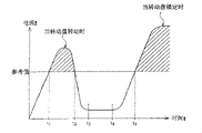
Fig. 7 is the accompanying drawing of electric current and time relationship in the demonstration first embodiment of the invention;
Fig. 8 is for showing the process flow diagram of the operation of Coin dispensing in the first embodiment of the invention;
Fig. 9 for show Coin dispensing in the second embodiment of the invention the accompanying drawing of section;
Figure 10 is a skeleton view, and it has shown in second embodiment of the invention, and the state of torque limiter and one-way clutch is set in follower gear;
Figure 11 is a planimetric map, and it has shown in second embodiment of the invention, and the state of torque limiter and one-way clutch is set in follower gear;
Figure 12 is the accompanying drawing of the section of torque limiter and one-way clutch in the demonstration second embodiment of the invention;
Figure 13 A and 13B are for being presented in the second embodiment of the invention, and when rolling disc stopped, electric current was with respect to the characteristic accompanying drawing of time;
Figure 14 A and 14B are for being presented in the second embodiment of the invention, and when rolling disc stopped, electric current was with respect to the characteristic accompanying drawing of time;
Figure 15 is a skeleton view, and it has shown in another embodiment of the present invention, and the method for torque limiter and one-way clutch is set in follower gear;
Figure 16 is a planimetric map, and it has shown and in the embodiment shown in Fig. 15 method of torque limiter and one-way clutch is set in follower gear.
Embodiment
Referring to accompanying drawing, they have shown the most preferred embodiment of Coin dispensing machine of the present invention.
Though the embodiment of " coin " depiler has been described herein, but, the present invention should not be limited to " coin " depiler and also pays article applicable to dispensing (payment or discharge), as any equipment of the used various game mediums of souvenir badge, souvenir or game machine.
Below, the Coin dispensing 1 of first embodiment of the invention is described with reference to the accompanying drawings.Fig. 1 is the skeleton view of an example of demonstration Coin dispensing 1.
As shown in Figure 1, the Coin dispensing 1 of present embodiment comprises 100, one rolling discs 200 of a charging basket, and a base 300.Charging basket 100 stores a plurality of coins 500.Charging basket 100 is removably fixed on the base 300 by mounting screw 400.
Base 300 provides a framework that is formed slopely with predetermined angular.Charging basket 100, rolling disc 200 grades are arranged on the top of base 300.Telling coin hole 600 is the escape hole that is used for discharging the coin 500 in the hole 211 that is contained in rolling disc 200.Telling coin hole 600 is communicated with in the inboard of rear portion with charging basket 100.
Structure and the peripheral accompanying drawing thereof of Fig. 2 for showing rolling disc 200.As shown in Figure 2, at the top, the fixing rolling disc 200 that drives by motor 260.Rolling disc 200 with the regulation spacing, be formed with for example about 4~8 circular ports 211 with ring-type.One circular coin dash receiver 212 is fixed on the lower surface of rolling disc 200.
Between rolling disc 200 and coin dash receiver 212, fix a coin and carry guide plate 213.Coin is carried guide plate 213 to form with ratchet-like and is had a lot of guiding pawls 214, and the quantity of guiding pawl is identical with hole 211 quantity on being formed on rolling disc 200.With an outer guide plate 220 be fixed to rolling disc 200 around.
Outside guide plate 220 has been formed centrally a circular-arc coin guiding face 215 therein, and the diameter of this guiding face is slightly less than the diameter of rolling disc 200.Being bearing in coin 500 on the coin dash receiver 212 by hole 211 remains on the guiding pawl 214 and when rolling disc 200 rotated, the direction (along its direction against coin guiding face 215) that the central shaft of rolling disc 200 is left on the edge was transferred.
Fig. 3 is for showing the accompanying drawing of the mechanism of telling coin part 230.As shown in Figure 3, tell coin part 230 and comprise 231, one mobile rollers 232 of a stationary roll and an outer side shifting roller 233.Telling coin part 230 is arranged on and tells near the coin hole 600.
When mobile roller 232 of coin 500 compressing and outer side shifting roller 233, coin hole 600 is told in mobile roller 232 and the 233 meeting opening and closing of outer side shifting roller.By the loaded member as volute spring, mobile roller 232 and outer side shifting roller 233 are loaded along closing the direction of telling coin hole 600.
As shown in Figure 3, when coin hole 600 was told in coin 500 arrival, because guiding pawl 214 moves, therefore, coin 500 made the position of mobile roller 232 and outer side shifting roller 233 move (part among Fig. 3 shown in the solid line).Coin 500 moves the position of mobile roller 232, tells coin hole 600 and is in the state of opening thereby can make.Make mobile roller 232 and outside the state of side shifting roller 233 before moving by shown in the dotted line among Fig. 3.
With when coin 500 contacts, coin 500 is in the position of crossing mobile roller 232 and outer side shifting roller 233 in the end of guiding pawl 214.Therefore, coin 500 can not receive the release action of guiding pawl 214, and the loaded member by mobile roller 232, is discharged from by bigger power.
Below, will the peripheral mechanism of rolling disc 200 be described.Fig. 4 is the perspective schematic view of the section of demonstration Coin dispensing 1.As shown in Figure 4, mainly be provided with a follower gear 256 and a motor 260 in the peripheral mechanism of rolling disc 200, described follower gear has the rotation axis 255 of rolling disc 200, and described motor has a driven wheel 261 that meshes with follower gear 256.
When CD-ROM drive motor 260, the rotation of driven wheel 261 is passed to follower gear 256, subsequently, follower gear 256 rotates rolling disc 200 by rotation axis 255.Below, will the details of the peripheral mechanism of rolling disc 200 be described.
Fig. 5 is the view of the detailed peripheral mechanism of demonstration rolling disc 200.As shown in Figure 5, rolling disc 200 is arranged on the inboard that is formed at the perforate of covering 221 centers.The rotation axis 255 of follower gear 256 is pressed in the hole 216 through a stationary installation 240, and this hole 216 is formed on the center that is arranged at the rolling disc 200 on the described perforate inboard.When the rotation axis 255 with follower gear 256 was pressed in the hole 216, fixedly rolling disc 200.Omission is arranged on the detail section on the rolling disc 200, as outside guide plate 220.
When gear assembly fixed part 241 being assemblied in the groove part 257 that is formed on the gear assembly main body 251, gear assembly fixed part 241 is for being used for fixing the parts of gear assembly 250.Especially as shown in Figure 5, each gear assembly fixed part 241 all forms a pawl in the end.Three pawls are assemblied in the groove part 257, thereby gear assembly 250 is fixed on the stationary installation 240.
Fig. 6 is the block diagram of the inner structure of demonstration Coin dispensing 1.As shown in Figure 6, Coin dispensing 1 comprises that one is told 22, one sensors 23 of 21, one current control units of 20, one current detecting units of coin control section and motor above-mentioned 260, and they link to each other by a bus 25.
Tell the whole Coin dispensing 1 of coin control section 20 controls.Particularly, when the command signal of the coin 500 that is used to send predetermined quantity by one of host CPU (not shown) input so that control when the whole game machine of Coin dispensing 1 is installed, is told coin control section 20 CD-ROM drive motor 260.Therefore, tell coin part 230 and discharge coin 500 from telling coin hole 600 one at a time.
Telling coin control section 20 can also be according to the quantity of the detectable signal calculating coin of sending 500 that is sent by sensor 23.When the counting of the coin of being sent reaches the specified quantity of coin, tell the rotation that coin control section 20 stops motor 260 immediately.
Current detecting unit 21 is for being used to detect the current detecting unit that flows into the electric current in the motor 260.Current detecting unit 21 comprises a plurality of resistance and can detect the electric current that flows in the motor 260 according to the local pressure ratio that is applied to ohmically voltage.
When the electric current that detects by current detecting unit 21 reached the predetermined reference value, current control unit 22 Control current were so that electric current is reduced to below the reference value.Owing to be easy to utilize known technology (as the STK681 device) that current detecting unit 21 and current control unit 22 are provided, therefore, will do not elaborate.
Fig. 7 flows into the accompanying drawing of the method for the electric current in the motor 260 for showing current control unit 22 controls.As shown in Figure 7, when motor 260 starts, rotate in order to make rolling disc 200, for motor 260, need bigger moment of torsion, therefore, bigger electric current flows into motor 260 with the passing of time.That is, starting the corresponding time intervals with motor 260 is 0~t2, and if current control unit 22 Control current not, the electric current that flows into motor 260 then can (left side dash area among Fig. 7) exceed described predetermined reference numerical value between time t1 and t2.In this case, current control unit 22 controls flow into the electric current in the motor 260, so that electric current is reduced under the referential data.
When through time interval of 0~t2 of starting corresponding to motor 260 and time interval when reaching t3~t4, the revolution of motor 260 is that the moment of torsion of rated revolution and motor 260 is a nominal torque.Owing to the obstruction that can not take place to be caused by coin, therefore, the electric current that flows into motor 260 this moment is the constant value less than reference value.
Subsequently, if the obstruction that caused by coin 500 has taken place and rolling disc 200 stops when surpassing t4, it is mobile then can act on bigger moment of torsion and bigger electric current on motor 260.The electric current that flows into motor 260 can increase with the passing of time and reach reference value when surpassing t5.In this case, current control unit 22 controls flow into the electric current of motor 260, so that electric current is reduced to below the reference value.
Coin dispensing 1 preferably have a notification unit (for example, sub-control circuit, loudspeaker or be installed in bulb on the game machine), it is used to make such notice, that is, current control unit 22 Control current are so that electric current is reduced to below the reference value.In this case, notification unit can be notified the user (the player of game machine, be provided with the employee or the operator of the amusement arcade (game arcade) of game machine) or any other device that links to each other with Coin dispensing 1: current control unit 22 Control current, so that electric current is reduced to below the reference value; Therefore, notification unit can be notified user or any other device: rolling disc 200 reason coins 500 cause obstruction and stop.
Before this, Coin dispensing can't provide and represent to determine state of (1) emptying coin 500 or (2) are caused the state of obstruction by coin 500 notice.But, in the present invention, notification unit can be notified user or any other unit: current control unit 22 Control current, so that electric current is reduced to below the referential data, therefore, notification unit only can provide the notice corresponding to state (2), and status recognition (1) and (2) each other.
In addition, the electric current of being surveyed when current control unit 22 control is so that electric current is reduced to referential data when following, notification unit can provide the notice about actual conditions, thereby for example, notify the employee in the amusement arcade with game machine that Coin dispensing 1 has been installed to produce the state that stops up at once and suitably, and can remove the described obstruction that produces by coin at once because of coin 500.
With reference to Fig. 8 the operation of the Coin dispensing among the embodiment 1 is described.Fig. 8 is for showing the process flow diagram of Coin dispensing 1 operation among this embodiment.
In step 210, current detecting unit 21 detects the electric current that flows into motor 260.In step 220, current control unit 22 determines whether the electric current (flowing into the electric current in the motor 260) that is detected by current detecting unit 21 reaches predetermined reference numerical value.If electric current is greater than predetermined reference numerical value, then operation reaches step 230; If electric current is equal to or less than predetermined reference numerical value, then repeating step 220.In step 230, the electric current that current control unit 22 controls are detected is so that electric current is reduced to below the referential data.
According to the present invention, when the electric current that is detected by current detecting unit 21 reaches predetermined reference numerical value, the electric current that current control unit 22 controls are detected is so that electric current is reduced to below the referential data, therefore, even when producing fault or when starting, Coin dispensing 1 can prevent that still excessive electric current from flowing in the motor 260 cause stopping up by coin.
Current detecting unit 21 or current control unit 22 should not be limited to comprise the hardware configuration of resistance or diode, also can adopt the program that can carry out process in current detecting unit 21 or the current control unit 22.
If the electric current that is detected by current detecting unit 21 (for example is equal to or greater than the predetermined reference current value, maximum allowed current value or load current value) constant times (for example, three times or bigger), then current control unit 22 can be controlled the electric current that detected so that electric current is reduced to below the referential data.
If the electric current that is detected by current detecting unit 21 is greater than making rolling disc 200 (for example rotate required lowest high-current value, at the t1 shown in Figure 7 and the lowest high-current value in the time interval between the t2), then current control unit 22 can be controlled the electric current that detected so that electric current is reduced to below the predetermined reference current value (for example, Zui Da allowed current value or load current value).
The electric current that is detected when current control unit 22 control is so that electric current is reduced to below the predetermined reference value, and when the predetermined reference time stopped, notification unit can provide the notice about actual conditions.For example, the obstruction that causes when rolling disc 200 reason coins 500 and when stopping, current control unit 22 can continue to control the electric current that is detected, so that electric current is reduced to below the predetermined reference value.On the other hand, if there is not to take place the obstruction that caused by coin 500, then current control unit 22 can be controlled the electric current that institute is detected, so that electric current only is reduced to below the predetermined reference value when rolling disc 200 startups.Therefore, if current control unit 22 Sustainable Control electric currents this means that coin 500 has taken place has caused obstruction, so notification unit can notify then the employee's coin 500 in the amusement arcade to cause obstruction.
As mentioned above, stop up or when starting, can prevent that still excessive electric current from flowing in the motor even the Coin dispensing of present embodiment 1 causes at coin.
Below, the Coin dispensing 10 to second embodiment among the present invention describes with reference to the accompanying drawings.
In a second embodiment, represent by identical reference number in the following drawings with reference to the identical parts of the parts of the former accompanying drawing description among first embodiment, therefore, they are not being described with the front.
In Coin dispensing 10, the peripheral mechanism of rolling disc 200 has adopted the structure of following explanation.Fig. 9 is the perspective schematic view of the section of demonstration Coin dispensing 10.As shown in Figure 9, mainly be provided with a follower gear 256 and a motor 260 in the peripheral mechanism of rolling disc 200, described follower gear has the rotation axis 255 of rolling disc 200, and described motor has a driven wheel 261 that meshes with follower gear 256.Rotation axis 255 (dash area among Fig. 9) at follower gear 256 is provided with a torque limiter 258 and an one-way clutch 270 (as described later).
Figure 10 is for showing the skeleton view of torque limiter 258.Figure 11 be from rotation axis 255 axially shown in the front elevation of torque limiter 258.Figure 12 is for showing the torque limiter 258 parallel with rotation axis 255 and the sectional view of one-way clutch 270.When rotate forward or backwards on motor 260 edges, if the load-torque that produces between the driving shaft of motor 260 and the rotation axis 255 of rolling disc 200 (or rotation axis 255 of follower gear 256) surpasses predetermined torque level, 258 of torque limiters play and are used to limit the effect of transmission restraint device that is passed to the rotating drive power of rolling disc 200 from motor 260.In this embodiment, forward is meant the direction (first direction) of dispensing coin 500, oppositely is to indicate to be regardless of the direction (second direction opposite with first direction) of sending coin 500.
The torque limiter 258 of present embodiment and the follower gear 256 formation one that are used for the driving torque of driven wheel 261 is passed to rolling disc 200, and be pressed in the rotation axis 255 of rolling disc 200.
Particularly, shown in Figure 10~12, torque limiter 258 is formed with follower gear 256 in periphery.Be sealed with lubricating oil in the gap between torque limiter 258 and rotation axis 255.
The driven wheel 261 that is arranged on the driving shaft of motor 260 contacts with follower gear 256.Therefore, the driving torque that appears on the driving shaft of motor 260 intactly can be delivered on the rotation axis 255 of follower gear 256.If coin 500 causing on the rolling disc 200 that the driving torque on the driving shaft that stops up and appear on the motor 260 does not make the rotation axis 255 of follower gear 256 rotate, then between the driving shaft of the rotation axis 255 of follower gear 256 and motor 260, can apply predetermined load (load-torque).In other words, between the rotation axis 255 of follower gear 256 and torque limiter 258 (in similar power on the driving shaft that is applied with and is applied to motor 260 on this torque limiter), apply predetermined load-torque.
If the load-torque that produces between rotation axis 255 and torque limiter 258 is no more than predetermined torque level, then torque limiter 258 and rotation axis 255 rotate with integral piece.It means: it is invalid to the rotating drive power that rolling disc 200 transmits that torque limiter 258 can prevent by motor 260.
On the contrary, if the load-torque that produces between rotation axis 255 and torque limiter 258 surpasses predetermined torque level, then torque limiter 258 and rotation axis 255 independent rotation.It means: it is invalid to the rotating drive power that rolling disc 200 transmits that torque limiter 258 makes by motor 260.
That is, if load-torque is no more than predetermined torque level, then torque limiter 258 allows and will be passed to rolling disc 200 by the rotation that motor 260 produces.If load-torque surpasses predetermined torque level, then torque limiter 258 restrictions are by the rotating drive power of motor 260 to rolling disc 200 transmission.
Fig. 1 3A has shown the obstruction (when torque limiter 258 is not set) that causes with reason coin 500 and the current value of relevant motor 260 when making rolling disc 200 stop (locking).Figure 13 B, 14A have shown the obstruction (when being provided with torque limiter 258) that causes with reason coin 500 with 14B and the current value of relevant motor 260 when making rolling disc 200 stop (locking).
In Figure 13 A, owing to produced obstruction by coin 500, therefore, current value is increased to about 5.7A, subsequently, though current value can once reduce, can be increased to stationary value (approximately 7.16A) once more.It means: owing to the rotation that makes rolling disc 200 that results in blockage with coin 500 stops (locking), therefore, for CD-ROM drive motor 260, excessive electric current flows in the driving circuit.
It is to be understood that the stationary value shown in Figure 13 A (approximately 7.16A) obviously greater than Figure 13 B that is provided with torque limiter 258, and the stationary value shown in 14A and the 14B (about 1.44A~2.78A).In other words, the stationary value that provides when torque limiter 258 (referring to Figure 13 A) is not set is compared, can further compress be provided with torque limiter 258 (referring to Figure 13 B, 14A, the stationary value that provides in the time of 14B).That is, torque limiter 258 can reduce to be applied to the load on the driving shaft of motor 260, and can reduce to flow into when locking rolling disc 200 overcurrent in the motor 260.
Figure 13 B, 14A and 14B also shown with progressively increase torque limiter 258 in the setting value of sliding torque the time relevant motor 260 current value.Figure 13 B, the setting value of sliding torque is 7.8kgfcm, 11.2kgfcm and 14.8kgfcm among 14A and the 14B.
As Figure 13 B, shown in 14A and the 14B, (14.8kgfcm->11.2kgfcm->7.8kgfcm), the stationary value of electric current reduces (2.78A->2.14A->1.44A) when the setting value of sliding torque reduces.Therefore, if when the setting value of the sliding torque in the torque limiter 258 is decreased to a certain degree, can compress stationary value.That is, if the setting of sliding torque is decreased to a certain degree,, can reduce to be applied to the load on the driving shaft of motor 260, and can reduce to flow into the overcurrent in the motor 260 then when locking during rolling disc 200.
When torque limiter 258 restriction by motor 260 during to rotating drive power that rolling disc 200 transmits (for example, when producing obstruction) because of coin, if along forward drive motor 260 (for example, forward rotation), then one-way clutch 270 can not be passed to the driving torque of motor 260 rolling disc 200; If reverse drive motor 260 (for example, backward rotation), 270 setting or bigger driving torques with motor 260 of one-way clutch are passed to rolling disc 200.That is, one-way clutch 270 has played the effect of transmission conversion equipment.As shown in figure 10, make the rotation axis 255 concentric settings of one-way clutch 270 and rolling disc 200.Prescribed torque above-mentioned in this embodiment is meant the maximum load moment of torsion that applied between torque limiter 258 and rotation axis 255 before torque limiter 258 idle running.
Particularly, when the obstruction that produces because of coin 500 occurring, according to the instruction from row's coin control section, reverse drive motor 260.When making motor 260 backward rotation, the rotation axis 255 of one-way clutch 270 locking rolling discs 200, and and the rotation of follower gear 256 together, with rotation axis 255 unitary rotation, thereby the driving torque of motor 260 is passed to rolling disc 200.Therefore, one-way clutch 270 can be removed the obstruction that coin 500 causes.The back will describe the detail operations of one-way clutch 270.
(1) is lower than under the situation of predetermined torque value at load-torque
Be lower than at load-torque under the situation of predetermined torque value, no matter whether motor 260 is to rotate forward or backwards, and torque limiter 258 all can not dally, thereby the rotating drive of motor 260 intactly is passed to the rotation axis 255 of rolling disc 200.At this moment, one-way clutch 270 rotates with follower gear 256 with identical speed, and therefore, the difference in rotation between the rotation axis 255 of one-way clutch 270 and rolling disc 200 is zero.
That is, one-way clutch 270 can not dally, and can not lock the rotation axis 255 (can not transmit the driving torque of motor 260) of rolling disc 200.State when in other words, one-way clutch 270 remains on the rotating drive that starts rolling disc 200.
One-way clutch 270 does not lock the rotation axis 255 of rolling disc 200, little by little rotates with the release conditions that locking direction makes rotation axis 255 never lock the rotation axis 255 of rolling disc 200 until one-way clutch 270.On the other hand, when locking the rotation axis 255 of rolling disc 200, one-way clutch 270 little by little rotates rotation axis 255 with the direction that is in release conditions, thereby removes the locking of rotation axis 255.
(2) surpass under the situation of predetermined torque value at load-torque
Surpass at load-torque under the situation of predetermined torque value, torque limiter 258 idle running, thereby between the rotation axis 255 of the rolling disc 200 of driving direction restriction, occur velocity contrast at the one-way clutch 270 that rotates with follower gear 256 with by the effect of torque limiter 258, and one-way clutch 270 enters the rotation axis 255 of release conditions or locking rolling disc 200 based on rotating forward or backwards of velocity contrast according to motor 260.
Promptly, when motor 260 along forward (along the direction of dispensing coin 500) when rotating, along making one-way clutch 270 be in the direction of release conditions, between the rotation axis 255 of one-way clutch 270 and rolling disc 200 velocity contrast appears, so that one-way clutch 270 keeps the locking of release conditions or releasing rotation axis 255.Therefore, one-way clutch 270 can not be passed to the rotating drive of motor 260 rotation axis 255 of rolling disc 200.
On the other hand, when motor 260 rotates along reverse (not sending the direction of coin 500), direction along one-way clutch 270 locking rotation axiss 255, between the rotation axis 255 of one-way clutch 270 and rolling disc 200 velocity contrast appears, so that one-way clutch 270 keeps locking rotation axis 255 or at first locks rotation axis 255.Therefore, one-way clutch 270 is passed to the rotating drive of motor 260 rotation axis 255 of rolling disc 200.
According to this embodiment, when rotate forward or backwards on motor 260 edges, if the load-torque that occurs between the rotation axis 255 of the driving shaft of motor 260 and rolling disc 200 surpasses predetermined torque value, then torque limiter 258 restrictions are passed to the rotating drive power of rolling disc 200 from motor 260, thereby Coin dispensing 10 can prevent when coin causes obstruction, excessive load is applied on the motor 260, flows in the motor 260 so that can prevent excessive electric current.
Can prevent that excessive load is applied on the driving shaft of motor 260, so that allow to make low intensive moulded parts etc. to be used for the drive system (for example, driven wheel 261) of motor 260.Therefore, can reduce the cost of drive system.
When torque limiter 258 limits the driving torque of motors 260 (when causing obstruction by coin), if motor is with backward rotation, then one-way clutch 270 is under the situation that does not make rolling disc 200 idle running, setting or bigger driving torque are passed to rolling disc 200, thereby when causing obstruction because of coin, Coin dispensing 10 can be removed the obstruction that coin causes.
Though above the example that torque limiter 258 and one-way clutch 270 are set on the rotation axis 255 of rolling disc 200 is illustrated, but, for example, if torque limiter 258 and one-way clutch 270 are arranged between the rotation axis 255 of the driving shaft of motor 260 and rolling disc 200, then torque limiter 258 and one-way clutch 270 can be arranged on any position.If between the rotation axis 255 of the driving shaft of motor 260 and rolling disc 200, form a plurality of neutral gears (for example, idle pulley), then torque limiter 258 and one-way clutch 270 can be arranged on any neutral gear.
As mentioned above,, when the obstruction that causes because of coin when rolling disc stops, then can preventing from motor, to apply bigger load, thereby can prevent that overcurrent from flowing in the motor and can remove the obstruction that coin causes according to this embodiment.
In first embodiment, as preventing that excessive load is applied to an example of the overload protective device on the drive unit, provides current detecting unit 21 and current control unit 22.In a second embodiment, the example of torque limiter 258 as overload protective device will be provided.But the present invention should not be limited to first or second embodiment, and can be used in combination any various mechanism and circuit provides overload protective device.
In a second embodiment, provided and contained the structure of torque limiter 258 as the transmission restraint device; But, when the load-torque between the rotation axis of the driving shaft of drive unit and rolling disc surpasses predetermined torque value, if the structure of transmission restraint device can limit from drive unit to the rotating drive power that rolling disc transmits, other parts can suitably be used in combination so and mechanism provides the transmission restraint device.For example, can provide the transmission restraint device by the control circuit that suitably is designed for accessory drive (motor 260 and drive system).
In a second embodiment, though provided and contained the structure of one-way clutch 270 as the transmission conversion equipment; But, if the structure of transmission conversion equipment at drive unit when the first direction of dispensing coin drives rolling disc, guarantee rotating drive power not to be passed to rolling disc, and under the state of transmission restraint device restriction rotating drive power, when drive unit drives rolling disc along the second direction opposite with first direction, guarantee rotating drive power is passed to rolling disc, then can be suitably in conjunction with utilizing other parts and mechanism that the transmission conversion equipment is provided.For example, can provide the transmission conversion equipment by the control circuit that suitably is designed for accessory drive (motor 260 and drive system).
In a second embodiment, Coin dispensing 10 for example comprises torque limiter 258 and one-way clutch 270.But, for example, in torque limiter 258 and the one-way clutch 270 can only be set in Coin dispensing 10.Figure 15 and 16 has shown when in Coin dispensing 10 one-way clutch 270 not being set, the topology example of the rotation axis 255 of rolling disc 200.
Shown in Figure 15 and 16, if one-way clutch 270 is not set on rotation axis 255, then torque limiter 258 can prevent that excessive load is applied on the motor 260, flows in the motor 260 so that prevent excessive electric current.
In order to constitute Coin dispensing, the torque limiter 258 and the one-way clutch 270 that can be used in combination the current detecting unit 21 that in first embodiment, discloses and current control unit 22 arbitrarily and disclose in a second embodiment.
Below, will the structure of the torque limiter 258 that is used in combination the current detecting unit 21 that discloses and current control unit 22 and discloses in a second embodiment in first embodiment be illustrated.In this case, the structure of Coin dispensing should be guaranteed: when current detecting unit 21 and current control unit 22 starts restriction and be supplied to the electric current of motor 260, if be applied to load on the drive system less than the load that in drive system, produces, the rotating drive power can restriction transmitted of torque limiter 258 then by drive system.
The Coin dispensing of Gou Chenging is provided with (a) based on the automatically controlled overload protection that forms by current detecting unit 21 and current control unit 22 thus; and the overload protection of (b) controlling based on the machinery that forms by torque limiter 258, and it constitutes to start the restriction under the mechanical control action than the lower load of load that starts the restriction under the automatically controlled effect.
According to this structure, torque limiter 258 can prevent that excessive load is applied on the motor 260 when causing obstruction because of coin, and can eliminate any other reason except that the obstruction that coin causes (as, abnormal occurrence in the driving circuit, and the mechanical fault of torque limiter 258) and make greater than the current supply of the rated current possibility to the motor 260.
By the way, also adoptable structure is: with than the low load of load that starts the described restriction under the mechanical control action, start the described restriction under the automatically controlled effect.
As mentioned above, according to first kind of structure of the present invention, provide a kind of Coin dispensing machine, it comprises a charging basket (for example, charging basket 100) of having stored a plurality of payment article (for example, coin 500); A rolling disc (for example, rolling disc 200), it is arranged on the bottom of charging basket and is formed with a plurality of holes that are used to receive the payment article; A drive unit (for example, motor 260, follower gear 256 etc.), it sends the payment article that are contained in the hole in proper order by making turn disc; And an overload protective device (for example, current detecting unit 21, current control unit 22, torque limiter 258), this device can prevent that excessive load is applied on the drive unit.
According to first kind of structure of the present invention, be provided with overload protective device, even so that causing when stopping up because of coin or when starting, Coin dispensing still can avoid excessive load to be applied on the drive unit.
Overload protective device can comprise that a detection is applied to the current detecting unit of the electric current on the drive unit; And a current control unit, it can control the electric current that is applied to drive unit, if so that the electric current that is detected by current detecting unit reaches the predetermined reference value, electric current still can be reduced under the predetermined reference value.According to this structure, even when causing that because of the payment article obstruction produces fault or when starting, Coin dispensing machine can prevent that still overcurrent from flowing in the motor.
Coin dispensing machine (for example can also comprise a notification unit, be installed in the sub-control circuit in the game machine that Coin dispensing is housed, microphone, lamp or analog), this notification unit is applied to the electric current of drive unit so that it when being reduced under the reference value, can notify the user in current control unit control.According to this structure, any other device that notification unit can be notified the user or link to each other with Coin dispensing: because rolling disc stops because of the obstruction that the payment article cause.
Up to now, traditional Coin dispensing machine can't provide determine state be (1) emptying payment article still (2) by paying the notice that article cause obstruction.But, in the present invention, notification unit then can be notified user or any other unit: thereby being limited current value, electric current is reduced to below the reference value, so that only can provide and the corresponding notice of state (2), and distinguishing state (1) and (2) each other.
If the electric current that is detected by current detecting unit (for example is equal to or greater than predetermined reference current numerical value, maximum allowed current value or load current value) constant times (for example, three times or bigger), then current detecting unit can be controlled the electric current that detected so that electric current is reduced to below the reference current numerical value.
If the electric current that is detected by current detecting unit is greater than (for example making the required lowest high-current value of turn disc, the t1 shown in Figure 7 and the lowest high-current value in the time interval between the t2), then current control unit can be controlled the electric current that detected so that electric current is reduced to below the predetermined reference current value (for example, Zui Da admissible current value or load current value).
The electric current that is detected when current control unit control is so that electric current is reduced to below the predetermined reference current value, and when the predetermined reference time stopped, described notification unit all can provide the notice about actual conditions.
Overload protective device (for example can comprise a transmission restraint device, torque limiter 258), if the load-torque that occurs between the rotation axis of the driving shaft of drive unit and rolling disc surpasses predetermined torque value, the transmission restraint device then can limit the rotating drive power that is passed to rolling disc by drive unit.According to this structure, stop up when causing rolling disc to stop when causing because of the payment article, Coin dispensing machine can avoid excessive loading on motor, thereby prevents that excessive electric current from flowing in the motor.
That is, if the load-torque that occurs between the rotation axis of the driving shaft of drive unit and rolling disc surpasses predetermined torque value, then the transmission restraint device makes that to be passed to the rotating drive power of rolling disc from drive unit invalid.When rotation was invalid, load can not crossed on the driving shaft that is applied to drive unit (motor) greatly.Because load can not crossed on the driving shaft that is applied to motor greatly, therefore, a large amount of electric currents of motor have been reduced to flow into.
If the transmission restraint device is arranged between the rotation axis of the driving shaft of drive unit and rolling disc, then the transmission restraint device can be arranged on any position.If between the rotation axis of the driving shaft of drive unit and rolling disc, form a plurality of neutral gears (for example, idle pulley), then the transmission restraint device can be arranged on any neutral gear.In addition, the transmission restraint device can be formed on the rotation that is used for drive unit and be passed to follower gear on the rolling disc, and can be assemblied in the rotation axis of rolling disc.
Overload protective device (for example can also comprise a transmission conversion equipment, one-way clutch 270), this device at drive unit when the first direction of dispensing payment article drives rolling disc, can suppress of the transmission of rotating drive power to rolling disc, and under the state of transmission restraint device restriction rotating drive power, when drive unit drives rolling disc along the second direction opposite with first direction, rotating drive power can be passed to rolling disc.
According to this structure, in Coin dispensing machine, when drive unit when first direction drives rolling disc, if the load-torque that occurs between the rotation axis of the rotation axis of drive unit and rolling disc surpasses predetermined torque value, the rotating drive power transmitted to rolling disc from drive unit of transmission restraint device restriction then; When the transmission restraint device limited the driving torque of drive unit, if drive unit drives rolling disc along second direction, then the transmission conversion equipment was passed to rolling disc with setting or bigger driving torque.Therefore, Coin dispensing machine can prevent excessive loading on motor, thereby has prevented that overcurrent from flowing in the motor, and can also remove the obstruction that is caused by the payment article.
If transmission restraint device and transmission conversion equipment are arranged between the rotation axis of the driving shaft of drive unit and rolling disc, then transmission restraint device and transmission conversion equipment can be arranged on any position.If between the rotation axis of the driving shaft of drive unit and rolling disc, form a plurality of neutral gears (for example, idle pulley), then transmission restraint device and transmission conversion equipment can be arranged on any neutral gear.In addition, the transmission restraint device can be formed on the rotation that is used for drive unit and be passed to follower gear on the rolling disc, and can press fit in the rotation axis of rolling disc.
In order to describe and to describe, most preferred embodiment of the present invention has been carried out above-mentioned explanation.But it should not thought limit or the present invention is confined in the disclosed specific pattern, and can obtain various modifications and variations according to above-mentioned enlightenment or by enforcement of the present invention.Embodiment selected and explanation is used to explain principle of the present invention and practical application thereof, so that can make those skilled in the art implement the present invention with various embodiment, and can make the various improvement that are applicable to designed special-purpose.Should expect: protection scope of the present invention is limited by the equivalent of claim with them.
Claims (7)
1. Coin dispensing machine, it comprises:
Be used to store the memory storage of a plurality of payment article;
Rolling disc, it is arranged on the described memory storage bottom and is formed with a plurality of holes that are used to receive the payment article;
Drive unit, it is used for the payment article that are contained in the hole by turn disc is sent in order; And
Overload protective device, it is used to prevent that excessive load is applied to described drive unit,
Wherein, described overload protective device comprises the transmission restraint device, and restriction rotating drive power passed to rolling disc from drive unit when its load-torque that is used for occurring between the rotation axis of the driving shaft of drive unit and rolling disc surpassed predetermined torque value,
Described overload protective device also comprises:
Current sensing means, it is used to detect the electric current that provides to drive unit;
Current control device, it is used for Control current, and electric current drops to below the predetermined reference value when reaching the predetermined reference value with convenient electric current.
2. Coin dispensing machine as claimed in claim 1 also comprises notifying device, is used for notice being exported to the user when the current control device Control current makes it drop to reference value when following.
3. Coin dispensing machine as claimed in claim 1, wherein drive unit comprises a follower gear that rotating drive power is passed to rolling disc; And
The transmission restraint device is formed in the follower gear.
4. Coin dispensing machine as claimed in claim 3, wherein transmission restraint device and follower gear are whole forms, and described transmission restraint device is assemblied in the rotation axis of rolling disc.
5. Coin dispensing machine as claimed in claim 1, wherein said transmission restraint device comprises torque limiter.
6. Coin dispensing machine as claimed in claim 1, wherein overload protective device also comprises the transmission conversion equipment, this transmission conversion equipment at drive unit when the first direction of dispensing payment article rotates rolling disc, can suppress of the transmission of rotating drive power to rolling disc, and under the state of transmission restraint device restriction rotating drive power, when drive unit rotates rolling disc along the second direction opposite with first direction, rotating drive power can be passed to rolling disc.
7. Coin dispensing machine as claimed in claim 6, wherein said transmission conversion equipment comprises one-way clutch.
Applications Claiming Priority (6)
| Application Number | Priority Date | Filing Date | Title |
|---|---|---|---|
| JP2003137850A JP4044486B2 (en) | 2003-05-15 | 2003-05-15 | Coin dispensing device |
| JP137850/2003 | 2003-05-15 | ||
| JP2003173741A JP4191542B2 (en) | 2003-06-18 | 2003-06-18 | Coin dispensing device |
| JP173741/2003 | 2003-06-18 | ||
| JP193024/2003 | 2003-07-07 | ||
| JP2003193024A JP4088562B2 (en) | 2003-07-07 | 2003-07-07 | Coin dispensing device |
Publications (2)
| Publication Number | Publication Date |
|---|---|
| CN1551051A CN1551051A (en) | 2004-12-01 |
| CN100407233C true CN100407233C (en) | 2008-07-30 |
Family
ID=33033094
Family Applications (1)
| Application Number | Title | Priority Date | Filing Date |
|---|---|---|---|
| CN200410043229XA Expired - Fee Related CN100407233C (en) | 2003-05-15 | 2004-05-14 | Coin dispensing machine |
Country Status (8)
| Country | Link |
|---|---|
| US (1) | US20050009464A1 (en) |
| EP (1) | EP1477941B1 (en) |
| CN (1) | CN100407233C (en) |
| AT (1) | ATE371917T1 (en) |
| AU (1) | AU2004202065A1 (en) |
| DE (1) | DE602004008531T2 (en) |
| ES (1) | ES2293119T3 (en) |
| ZA (1) | ZA200403739B (en) |
Families Citing this family (9)
| Publication number | Priority date | Publication date | Assignee | Title |
|---|---|---|---|---|
| EP1717762B1 (en) * | 2005-04-28 | 2010-02-24 | Asahi Seiko Kabushiki Kaisha | Coin dispensing method for coin dispensing device and coin dispensing device, and coin recycling machine using the coin dispensing device |
| JP5066673B2 (en) * | 2006-10-12 | 2012-11-07 | 旭精工株式会社 | Coin hopper |
| TWM441885U (en) * | 2011-09-15 | 2012-11-21 | teng-yu Huang | Power separation financial affairs machine |
| CN102831700B (en) * | 2012-08-17 | 2015-05-13 | 广州广电运通金融电子股份有限公司 | Coin processing device |
| JP6002929B2 (en) * | 2013-01-28 | 2016-10-05 | 旭精工株式会社 | Coin dispenser |
| JP5945752B2 (en) * | 2013-03-08 | 2016-07-05 | 旭精工株式会社 | Coin dispenser |
| WO2015123712A1 (en) * | 2014-02-24 | 2015-08-27 | Fts Computertechnik Gmbh | Method and computer network for transmitting messages |
| CN106851042A (en) * | 2017-01-23 | 2017-06-13 | 宁波华高信息科技有限公司 | A kind of scanner |
| CN114011733A (en) * | 2021-10-29 | 2022-02-08 | 苏州英诺威视图像有限公司 | Glass disc protection system and glass disc protection method |
Citations (9)
| Publication number | Priority date | Publication date | Assignee | Title |
|---|---|---|---|---|
| US4398550A (en) * | 1981-04-24 | 1983-08-16 | Standard Change-Makers, Inc. | Coin dispensing mechanism |
| US5170676A (en) * | 1989-08-25 | 1992-12-15 | General Motors Corporation | Torque limiter |
| JPH0785333A (en) * | 1993-09-14 | 1995-03-31 | Universal Hanbai Kk | Hopper device |
| JPH09319908A (en) * | 1996-05-31 | 1997-12-12 | Universal Hanbai Kk | Coin paying-out device |
| GB2355104A (en) * | 1999-08-06 | 2001-04-11 | Asahi Seiko Co Ltd | Coin hopper apparatus |
| JP2002222446A (en) * | 2001-01-25 | 2002-08-09 | Juki Corp | Coin pay-out device |
| US20020170801A1 (en) * | 2001-05-04 | 2002-11-21 | Martin Douglas A. | Automatic coin input tray for a self-service coin-counting machine |
| JP2002366999A (en) * | 2001-06-13 | 2002-12-20 | Asahi Seiko Kk | Hopper provided with shutter |
| JP2003115068A (en) * | 2001-10-04 | 2003-04-18 | Hiromi Matsushita | Hopper type coin payout device |
Family Cites Families (8)
| Publication number | Priority date | Publication date | Assignee | Title |
|---|---|---|---|---|
| DE3686965T2 (en) * | 1985-07-17 | 1993-07-08 | Universal Oyama Kk | DEVICE FOR ISSUING COINS. |
| KR100309355B1 (en) * | 1993-09-07 | 2001-12-15 | 오까다 마사하루 | Cure Dispenser |
| US6039645A (en) * | 1997-06-24 | 2000-03-21 | Cummins-Allison Corp. | Software loading system for a coin sorter |
| US5997395A (en) * | 1998-03-17 | 1999-12-07 | Cummins-Allison Corp. | High speed coin sorter having a reduced size |
| JP2001271903A (en) * | 2000-01-17 | 2001-10-05 | Honda Motor Co Ltd | Power transmission device for work machine |
| US6712191B2 (en) * | 2001-03-12 | 2004-03-30 | Jcm American Corporation | Enhanced bezel for currency acceptor |
| DE10253405A1 (en) * | 2001-11-22 | 2003-06-18 | Nifco Inc | extracting device |
| US6933693B2 (en) * | 2002-11-08 | 2005-08-23 | Eaton Corporation | Method and apparatus of detecting disturbances in a centrifugal pump |
-
2004
- 2004-05-13 US US10/844,605 patent/US20050009464A1/en not_active Abandoned
- 2004-05-14 AU AU2004202065A patent/AU2004202065A1/en not_active Abandoned
- 2004-05-14 EP EP04011562A patent/EP1477941B1/en not_active Not-in-force
- 2004-05-14 DE DE602004008531T patent/DE602004008531T2/en active Active
- 2004-05-14 ES ES04011562T patent/ES2293119T3/en active Active
- 2004-05-14 AT AT04011562T patent/ATE371917T1/en not_active IP Right Cessation
- 2004-05-14 CN CN200410043229XA patent/CN100407233C/en not_active Expired - Fee Related
- 2004-05-14 ZA ZA2004/03739A patent/ZA200403739B/en unknown
Patent Citations (9)
| Publication number | Priority date | Publication date | Assignee | Title |
|---|---|---|---|---|
| US4398550A (en) * | 1981-04-24 | 1983-08-16 | Standard Change-Makers, Inc. | Coin dispensing mechanism |
| US5170676A (en) * | 1989-08-25 | 1992-12-15 | General Motors Corporation | Torque limiter |
| JPH0785333A (en) * | 1993-09-14 | 1995-03-31 | Universal Hanbai Kk | Hopper device |
| JPH09319908A (en) * | 1996-05-31 | 1997-12-12 | Universal Hanbai Kk | Coin paying-out device |
| GB2355104A (en) * | 1999-08-06 | 2001-04-11 | Asahi Seiko Co Ltd | Coin hopper apparatus |
| JP2002222446A (en) * | 2001-01-25 | 2002-08-09 | Juki Corp | Coin pay-out device |
| US20020170801A1 (en) * | 2001-05-04 | 2002-11-21 | Martin Douglas A. | Automatic coin input tray for a self-service coin-counting machine |
| JP2002366999A (en) * | 2001-06-13 | 2002-12-20 | Asahi Seiko Kk | Hopper provided with shutter |
| JP2003115068A (en) * | 2001-10-04 | 2003-04-18 | Hiromi Matsushita | Hopper type coin payout device |
Also Published As
| Publication number | Publication date |
|---|---|
| DE602004008531D1 (en) | 2007-10-11 |
| EP1477941A1 (en) | 2004-11-17 |
| DE602004008531T2 (en) | 2007-12-27 |
| AU2004202065A1 (en) | 2004-12-02 |
| EP1477941B1 (en) | 2007-08-29 |
| ATE371917T1 (en) | 2007-09-15 |
| ZA200403739B (en) | 2005-02-23 |
| ES2293119T3 (en) | 2008-03-16 |
| US20050009464A1 (en) | 2005-01-13 |
| CN1551051A (en) | 2004-12-01 |
Similar Documents
| Publication | Publication Date | Title |
|---|---|---|
| CN100407233C (en) | Coin dispensing machine | |
| US4635937A (en) | Amusement machine | |
| US6626751B1 (en) | Compact dual power transmission mechanism for a coin hopper | |
| JP4473416B2 (en) | Pachinko machine ball dispenser | |
| US5976052A (en) | Differential selection automatic gear change device for pedal vehicles | |
| CN104471621A (en) | Probabilistic vending machine, and driving apparatus and method thereof | |
| JP4191542B2 (en) | Coin dispensing device | |
| JP3407425B2 (en) | Medals sending device | |
| JP2004195131A (en) | Ball put out device for game machine | |
| JP3627250B2 (en) | Pachinko ball release device | |
| JP2003062270A (en) | Ball paying out apparatus | |
| JP3486931B2 (en) | Structure to prevent accidental outflow of pachinko ball discharge device | |
| JP4044486B2 (en) | Coin dispensing device | |
| JP3310714B2 (en) | Premium ball payout device for pachinko machines | |
| JP3042253U (en) | Pachinko ball release device | |
| JP4181646B2 (en) | Pachinko ball ejection device | |
| JPH08103546A (en) | Pachinko machine | |
| JPS6132474Y2 (en) | ||
| JP3815743B2 (en) | Pachinko ball dispenser | |
| JPH0464379A (en) | Premium ball paying-off device of pinball machine | |
| JP3745391B2 (en) | Ball dispenser | |
| JP3760817B2 (en) | Pachinko ball feeding device | |
| EP0217551A1 (en) | Rotary escapement mechanism | |
| JP3760811B2 (en) | Pachinko ball feeding device | |
| JP4535569B2 (en) | Pachinko machine ball dispenser |
Legal Events
| Date | Code | Title | Description |
|---|---|---|---|
| C06 | Publication | ||
| PB01 | Publication | ||
| C10 | Entry into substantive examination | ||
| SE01 | Entry into force of request for substantive examination | ||
| C14 | Grant of patent or utility model | ||
| GR01 | Patent grant | ||
| C56 | Change in the name or address of the patentee |
Owner name: ARUZE CORPORATION Free format text: FORMER NAME: ARUZE CORP. |
|
| CP01 | Change in the name or title of a patent holder |
Address after: Tokyo, Japan, Japan Patentee after: Global Entertainment Corporation Address before: Tokyo, Japan, Japan Patentee before: Aruze Corp. |
|
| CF01 | Termination of patent right due to non-payment of annual fee | ||
| CF01 | Termination of patent right due to non-payment of annual fee |
Granted publication date: 20080730 Termination date: 20190514 |